Pre-feasibility report
|
|
|
- Noah Patterson
- 5 years ago
- Views:
Transcription
1 Pre-feasibility report Suryadev Alloys & Power Pvt. Ltd. [] at Sirupuzhalpet and New Gummidipoondi Village, Gummidipoondi Taluk,Tiruvollur District, Tamil Nadu 0
2 Chapter - 1 EXECUTIVE SUMMARY 1.1 ABOUT PROJECT PROPONENT Suryadev Alloys & Power Pvt. Ltd. are one of the leading manufacturer of steel products, with a wide and specialized range in TMT and Wire Rod Coils. Shri. Mukesh Agarwal is Managing Director of the company. SURYADEV QST (Quenching and Self Tempering) rebars are manufactured in Technical Collaboration with Hennigsdorfer Stahl Engineering GmbH Germany, who has supplied their THERMEX cooling Technology in over 100 steel plants allover world including SAIL, first in Tamilnadu. SURYADEV QST rebars are manufactured only from IS 2830 : 1992 grade billets which are manufactured from our own twin furnaces with a capacity of 800 MT/day, in Technical Collaboration with Electrotherm. First in Tamilnadu with straight and continuous mill with world class cooling bed, one of the largest in India and equipped with electromagnetic arrays. It is the process which gives SURYADEV QST unmatched quality. The Company was promoted by a young entrepreneur Mr. Mukesh Agarwal with his brother Mr. Pankaj Agarwal. The promoters are in iron and steel businesses and having good reputation in the market, which was gained with good business practices. 1.2 ABOUT THE PROPOSED PROJECT Suryadev Alloys & Power Pvt. Ltd. is existing plant located in New Gummidipoondi, Gummidipoondi Taluk, Tiruvallur District, Tamilnadu, with a production capacity of 1,40,000 TPA of Sponge Iron, 1,40,000 TPA of Billets & 1,40,000 TPA of Rolled products. Now as part of expansion, Suryadev Alloys & Power Pvt. Ltd. is planning to go for expansion with the following plant configuration and production capacity: S.No. Products/ Units EC obtained in 2011 Present proposal Total after expansion 1. Sponge Iron through DRI 2,31,000 TPA 3,30,000 TPA 3,30,000 TPA Kilns (4 x 175 TPD) (2 x 500 TPD) 2. Sinter through Sinter plant ,08,000 TPA (1 x 2880 TPD) 10,08,000 TPA 3. Pig Iron through Blast Furnace 4. Billets through Induction Furnace and Arc Furnace --- 7,56,000 TPA (1 x 2160 TPD) 12,50,000 TPA Billets through IF/ Converter (BOF) / Arc Furnace 7,56,000 TPA 12,50,000 TPA 1
3 5. Rolled Products 12,00,000 TPA ,00,000 TPA (Wire Rods & Bars) 6. Power Plant (WHRB) 1 x 15 MW 2 x 15 MW 30 MW 5. Power Plant (utilising Blast furnace gases) - 1 x 30 MW 30 MW 6. Power Plant 2 x 80 MW (CFBC based) 1x 330 MW (PCF based) 490 MW 7. Ferro Manganese TPA ,000 TPA 8. Silico Manganese TPA ,000 TPA 9 Oxygen plant x 400 TPD 400 TPD Captive Power Plant: Continuous non availability of Indian Coal and the increased dependence on imported coal has prompted us to plan for a higher capacity power plant, which would be more fuel efficient than a lower capacity plant. Accordingly we have examined th e best technology available today and have firmed up our plan for 330 MW PCF based plant, which gives us the best economic feasibility and viability on the long run. Simultaneously, as we are setting up a Blast Furnace, we propose to use the BF Gas for generating additional 30 MW (1 x 30) of power. Also WHRB of 30 MW (in place of 45 proposed earlier) from the Sponge Iron Kiln. Thus the CPP configuration will now be : Existing running plant : 160 (2 x 80) MW WHRB : 30 (2 x15) MW Gas based co-gen : 30 (1 x 30) MW Power Plant (PCF) : 330 (1 x 330) MW Electrical Energy Consumption: Apprx 400 MW will be used inhouse including auxiliary and steel plant within the premises. i. With Sinter Plant + Blast Furnace + Sponge Iron plant + Converter (BOF) + Oxygen plant + Ladle Furnace + VD+ Caster + Rolling Mill & All other utilities put together will require about 1300 Kwh/Ton of Salable steel. ii. Ferro Manganese / Silico Manganese to the extent of about 400 Tons per day then additional energy requirement will be about 3000 to 3500 Kwh/ ton of Ferro alloy produced. 2
4 1.2 Total available land with the management is acres, i.e acres is existing plant and 45 acres of land is a djoining the existing land. 1.3 Water is required for process of manufacturing, cooling and domestic purpose, which will be met from Ground water source. 1.4 The project cost estimated for the proposed steel plant and CPP is Rs Crores. This is inclusive of equipment cost as erected including Civil and structural works, taxes & duties and contingencies. As mentioned above the promoters & key personal are experienced, energetic and resourceful men with good reputation and business links. The promoters are also financially stable & will be able to execute the project successfully & in specified time & run it profitability & smoothly in future too. 3
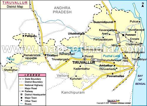
5 Chapter - 2 INTRODUCTION OF THE PROJECT/ BACKGROUND INFORMATION 2.1 Identification of project and project proponent SAPPL plant is situated at Sirupuzhalpet and New Gummidipoondi Village, Gummidipoondi Taluk, Tiruvollur District, Tamil Nadu. 2.2 Brief description of nature of the project Suryadev Alloys & Power Pvt. Ltd. is existing plant located in New Gummidipoondi, Gummidipoondi Taluk, Tiruvallur District, Tamilnadu, with a production capacity of 1,40,000 TPA of Sponge Iron, 1,40,000 TPA of Billets & 1,40,000 TPA of Rolled products. Now as part of expansion, Suryadev Alloys & Power Pvt. Ltd. is planning to go for expansion with the following plant configuration and production capacity: S.No. Products/ Units EC obtained in 2011 Present proposal Total after expansion 1. Sponge Iron through DRI Kilns 2,31,000 TPA (4 x 175 TPD) 3,30,000 TPA (2 x 500 TPD) 2. Sinter through Sinter plant ,08,000 TPA (1 x 2880 TPD) 3. Pig Iron through Blast Furnace 4. Billets through Induction Furnace and Arc Furnace 3,30,000 TPA 10,08,000 TPA --- 7,56,000 TPA (1 x 2160 TPD) 7,56,000 TPA 12,50,000 TPA Billets through IF/ 12,50,000 TPA Converter (BOF) / Arc Furnace 12,00,000 TPA ,00,000 TPA 5. Rolled Products (Wire Rods & Bars) 6. Power Plant (WHRB) 1 x 15 MW 2 x 15 MW 30 MW 5. Power Plant - 1 x 30 MW 30 MW (utilising Blast furnace gases) 6. Power Plant 2 x 80 MW 1x 330 MW 490 MW (CFBC based) (PCF based) 7. Ferro Manganese TPA ,000 TPA 8. Silico Manganese TPA ,000 TPA 9 Oxygen plant x 400 TPD 400 TPD 4
6 2.3 Need for the project and its importance to the country and or region. Indian steel industry is undergoing a period of restructuring, improving its ranking among global steel producers from the 9 th place to the 6 th place. In the last 5 years, the production and consumption of steel has grown at exceeding rates of 9% per annum. The pace of growth has further accelerated in the current year to over 10%. The 11 th Five Year Plan projects a 9% average annual growth in our GDP. Higher expectations to see a massive increase in investment in infrastructure is probable. Consequently, massive growth in demand for steel in the next few decades is also credible perhaps to levels never visualized before. 2.4 Employment Generation (Direct and Indirect) due to the project. The local areas will be benefited by way of generation of employment opportunities, increased demand for local products and services. There will be an overall improvement in the income level of the local people. The project creates employment to about 1500 persons once the plant comes to the operational stage and for 2000 persons during construction stage. Top priority will be given to locals for Semi-Skilled and Unskilled jobs. With the development of this Plant there will be lot of scope for more ancillary development, which in turn will benefit the nation. There will be a certain enhancement of educational and medical standards of people in the study area. There will be generally positive and be neficial impacts by way of economic improvements, transportation, aesthetic environment and business generation. There will be an overall upliftment of socio-economic status of people in the area with the implementation of the project. ***** 5
7 Chapter 3 PROJECT DESCRIPTION 3.1 Type of project including interlinked and interdependent projects: Type of Project: The proposed project is steel plant comprising of Blast Furnace, Sinter Plant, Converter BOF/Arc Furnace, Sponge Iron, Oxygen plant and Power plant (WHRB and Pulverized Coal Fire boiler). 1. Iron Ore fines will be used in the Sinter Plant to make Sinter. 2. Iron Ore lumps & Sinter will be used in Blast Furnace to make Hot Metal. 3. Hot Metal & Scrap/Sponge will be used in Converter/Arc Furnace to produ ce liquid steel 4. Sponge Iron and other additives like Ferro alloys and scraps will be melted in and Steel Ingots/ Billets are casted through Caster. 5. These manufactured Steel Ingots/ Billets are heated in re-heating furnace and rolled products produced. 6. Power will be generated using Pulverized Coal Fired Boiler Interlinked Project: No interlinked project is envisaged. 3.2 General Location: Proposed project will be establishment in the existing plant premises and land adjacent to the existing plant. Total land envisaged for the entire project is acres (Existing plant acres + adjacent land 45.0 acres). The proposed steel plant will be installed at Sirupuzhalpet and New Gummidipoondi Village, Gummidipoondi Taluk, Tiruvollur Dis trict, Tamil Nadu. Existing Plant Survey no.s 281 to 290, , 297/2, 297/1A to 297/1D, 298 of New 6
8 ( acres) UNIT # 1 Proposed land (45 acres) UNIT # 2 Gummidipoondi Village and 78,80 to 111 of Sirupuzhalpettai Village Survey no.s 287/1A, 287/2, 287/3, 290/1, 291/1A, 291/1B, 291/4, 291/5 of New Gummidipoondi Village and 78/1, 78/2A1, 78/2A2, 78/2C, 78/2D, 78/2E, 81/1B, 81/2A, 81/2B, 81/2C of Sirupuzhalpettai Village The location map is shown below: 7
9 8
10 3.3 Details of alternate sites considered: The proposed plant site is in accordance with MoEF guidelines as mentioned below, the present site has been chosen for the proposed Steel Plant. There are no National Parks / Sanctuaries within 10 Km. radius of the plant site. There are no historical places/places of tourist importance within 10 Km. radius of the plant site. Nearest Village (Tandalacheri) is situated at a distance of 1.0 Km from the plant site. Nearest river (Arani river) is flowing at a distance of 3.4 Km from the plant site. Interstate border of Tamilnadu Andhra Pradesh is at a di stance of 9.5 Km from the proposed site. No Forest land is involved in the site. No R & R is involved. 3.4 Size or magnitude of operation. The plant configuration & production capacity of proposed expansion of steel plant is given as below: S.No. Products/ Units EC obtained in 2011 Present proposal Total after expansion 1. Sponge Iron through DRI Kilns 2,31,000 TPA (4 x 175 TPD) 3,30,000 TPA (2 x 500 TPD) 3,30,000 TPA 2. Sinter through Sinter plant ,08,000 TPA 10,08,000 TPA (1 x 2880 TPD) 3. Pig Iron through Blast --- 7,56,000 TPA 7,56,000 TPA Furnace (1 x 2160 TPD) 4. Billets through Induction 12,50,000 TPA Billets through IF/ 12,50,000 TPA Furnace and Arc Furnace Converter (BOF) / Arc Furnace 5. Rolled Products 12,00,000 TPA ,00,000 TPA (Wire Rods & Bars) 6. Power Plant (WHRB) 1 x 15 MW 2 x 15 MW 30 MW 5. Power Plant - 1 x 30 MW 30 MW (utilising Blast furnace gases) 6. Power Plant 2 x 80 MW 1x 330 MW 490 MW (CFBC based) (PCF based) 7. Ferro Manganese TPA ,000 TPA 8. Silico Manganese TPA ,000 TPA 9 Oxygen plant x 400 TPD 400 TPD 9
 or Magnetite (Fe3O4) and the iron content ranges from 50% to 70%.")
11 3.5 Manufacturing Process and Flow Diagram: Manufacturing Process Sponge Iron Blast Furnace: Iron oxides can come to the blast furnace plant in the form of raw ore, pellets or sinter. The raw ore is removed from the earth and sized into pieces that range from 0.5 to 1.5 inches. This ore is either Hematite (Fe2O3) or Magnetite (Fe3O4) and the iron content ranges from 50% to 70%. This iron rich ore can be charged directly into a blast furnace without any further processing. Iron ore that contains a lower iron content must be processed or beneficiated to increase its iron content. Pellets are produced from this lower iron content ore. This ore is crushed and ground into a powder so the waste material called gangue can be removed. The remaining iron -rich powder is rolled into balls and fired in a furnace to produce strong, marble-sized pellets that contain 60% to 65% iron. Sinter is produced from fine raw ore, small coke, sand -sized limestone and numerous other steel plant waste materials that contain some iron. These fine materials are proportioned to obtain a desired product chemistry then mixed togeth er. This raw material mix is then placed on a sintering strand, which is similar to a steel conveyor belt, where it is ignited by gas fired furnace and fused by the heat from the coke fines into larger size pieces that are from 0.5 to 2.0 inches. The iron ore, pellets and sinter then 10
12 become the liquid iron produced in the blast furnace with any of their remaining impurities going to the liquid slag. The final raw material in the ironmaking process in limestone. The limestone is removed from the earth by blasting with explosives. It is then crushed and screened to a size that ranges from 0.5 inch to 1.5 inch to become blast furnace flux. This flux can be pure high calcium limestone, dolomitic limestone containing magnesia or a blend of the two types of limestone. Since the limestone is melted to become the slag which removes sulfur and other impurities, the blast furnace operator may blend the different stones to produce the desired slag chemistry and create optimum slag properties such as a low melting point and a high fluidity. All of the raw materials are stored in an ore field and transferred to the stockhouse before charging. Once these materials are charged into the furnace top, they go through numerous chemical and physical reactions while descending to the bottom of the furnace. The iron ore, pellets and sinter are reduced which simply means the oxygen in the iron oxides is removed by a series of chemical reactions. DRI process: For the direct reduction of iron ore, the main furnace used is Rotary Kiln. The rotary kiln is a refractory lines vessel on which several blowers are mounted. From the blowers, air pipes go through the shell and refractory. Vertically and delivers the required amount of air required for process, axially. The kiln has conical outlet and inlet holds the material in the kiln. Kiln is placed in a slope from feed end side at a slope of 2 ½ degrees. Iron ore, Coal, Dolomite/ Limestone is fed in the weighed quantity and the kiln is rotated at the speed of about 0.5 rpm. A temperature between 1000OC to 1050 OC is maintained in about 70% of the kiln length towards discharge and side for required reaction. After the reaction, the product is taken into an indirect cooling drum cooler. The produ ct is cooled to 100OC and taken for product separation. The product screened into lumps and fines is separated from the coal ash and coal char and then taken for final use. 11

13 The waste gas from the kiln contain lot of combustible like coal volatiles, unused CO, about 10 to 12% carbon particles and lot of other dust. The gas is taken to an after burner chamber and after the combustibles are burnt, the gas is cooled to about 160OC either passing through a gas cooling tower or through a waste heat recovery boil er before going to Stack via ESP and ID fans. The construction of Kiln and Cooler is made in such a way that no outside air is allowed to go into the system. The outside air if goes to the kiln, re -oxidizes the product ultimately upsetting the temperature profile. To avoid this, ID fan damper is throttled to maintained positive pressure in the Kiln. The pressure of about +5mm water column is maintained at Kiln firing hood. The rotational speed of the kiln is adjusted as per the feed rate and percentage of metallization. The % of inclination, rotational speed, the length of time the material is exposed to atmosphere, the kiln temperature, are all to be taken into consideration. So the kiln has three functions: 1. It is heat exchanger. 2. It is a vessel for Chemical reaction. 3. It is a conveyor of solids. Figure of manufacturing process is shown below: 12

14 3.6 Raw material requirement, Transport etc.: Raw Material Requirement and its sources: Iron ore, coal & limestone will be used in the proposed Sponge Iron plant Mode of Transport for Raw materials and finished products: The aforesaid raw materials are transported through rail up to the nearest available rail head and thereafter the same will be transported to the site through tarpaulin covered trucks Market of Final Products: It is proposed to install steel plant with special rolled products facility. As the steel/ power sector had huge demand and supply ga p. Hence marketing of the product has no problem. 3.8 Availability of water its source, Energy / power requirement and source: Water Requirement and its sources: Water will be required for the operation of proposed steel plant. Water required for th e expansion project will be 5770 KLD. The desired quantity of water will be drawn met from Ground water resource. As well as water reservoirs being set up within the land acquired for the purpose. Water drawl permission from CGWA has been obtained. 13
15 3.8.2 Sources of Energy/ Power and its sources: The type of Energy/ power sources for proposed steel plant is given as below: Sr. No Units Sources Energy/ Power Its origin 1. Sponge Iron Electric Power TNEB grids/cpp 2. Blast Furnace/Sinter etc Electric Power TNEB grids/cpp 3.9 Generation and disposal of Wastes [Waste Water and Solid Wastes]: Waste Water Generation: There will be no effluent generation in the DRI as closed circuit cooling system will be adopted. Effluent from power plant such as boiler blowdown, DM Plant regeneration. Initially the acidic and alkaline effluent streams coming from cation and anion units of DM plant will be neutralized in a neutralization tank. Service water will then pass through a n Oil Separator to remove the oil content in the effluent. The ph of Boiler blowdown will be between 9.5 and Hence this effluent stream shall be neutralized in a neutralization tank before mixing with other effluent streams. All these effluent streams will be mixed in a Central Monitoring Basin along with cooling tower blowdown. Treated effluent will be used for ash conditioning, dust suppression and for greenbelt development. The sanitary wastewater will be treated in septic tank followed by subsurface dispersion trench. Hence there will not be any chance of contamination of water bodies due to proposed project Solid Waste Generation and its disposal Dolochar generated from the Sponge iron will be utilized in the Power plant, Fly Ash generated will be given to Asbestos Cement sheet units. Bottom ash will be given to Cement / Brick manufacturers etc. are the solid wastes to be generate due to operation of proposed steel plant. The following table depicts the expected quantities of various solid wastes: 14
16 The following table depicts the expected solid wastes: Sr. No Solid wastes Quantity 1. Dolochar Utilized in existing FBC boiler 2. Accretion slag Will be Used in Road construction 3. Wet scraper sludge Will be given to brick manufacturers 4. Ash & Dust from DRI Will be given to Cement plant 5. Granulated slag Will be given to Cement plant 6. GCP Sludge Will be used in Sinter plant 15
17 Chapter 4 SITE ANALYSIS This chapter gives details regarding type of land; land use, topography and site connectivity etc. The details are as follows: 4.1 Connectivity The proposed site is well connected with Rail and Road connectivity. The nearest railway station is Gummdipundi RS. The following table gives brief regarding connectivity of the proposed site: Component Description Road : NH 5 at distance of 3.0 Kms. Rail : Nearest station 3.2 km is Gummdipundi RS Air : Chennai 45 km Sea Port : Chennai 40 km 4.2 Land Form, Land use and Land ownership Land Form: Present is more or less flat terrain Land Use of the Project Site Present land use of the proposed site is Barren however few single crop patches are involve. 4.3 Topography Topography of land is more or less flat terrain without much undulation. 4.4 Existing land use pattern: Land use pattern of the Project site Total land in possession of management is acres i.e acres of existing plant and 45 acres of land adjoining land. 16
18 4.4.2 Environmental Setting of the Project Site: Below mentioned table gives brief regarding environmental setting of the project site: Sr. No Particulars Distance from the site 1. National Park = Nil 2. Wild life sanctuaries = Nil 3. Reserve Forest = Palavakkam RF (4.8 Km.) 4. Protected Forest = Nil 5. Eco Sensitive Areas = Pulicat lake (12.5 Km) 6. River flowing = Arani River (3.4 Km) 7. Costal Regulation Zone [CRZ] = Nil 8. Nearest Village = Tandalacheri (1.0 Km) 9. Industrial Area = SIPCOT 2 Kms 4.5 Existing Infrastructure All required infrastructure is prevailing in the site. 4.6 Soil classification The soils in the area are generally of clayey loam types with sandy loam soil in some areas. 4.7 Climatic data from secondary sources The climatic condition of this area is semi-arid. The maximum temperature goes upto 48ºC during summer in the month of May and the minimum temperature goes down to 10.0ºC during winter in the month of January-February. The winds in the area are light to moderate during summer and winter. The rainfall of the district is 1000 mm. Generally light to moderate winds prevails throughout the year. Winds were light and moderate particularly during the morning hours. While during the afternoon hours the winds were stronger. 17
19 Chapter 5 PLANNING BRIEF 5.1 Planning Concept: The proposed project is steel plant comprising of Blast Furnace, Sinter Plant, Converter BOF/Arc Furnace, Sponge Iron, Oxygen plant and Power plant (WHRB a nd Pulverized Coal Fire boiler) at Sirupuzhalpet and New Gummidipoondi Village, Gummidipoondi Taluk, Tiruvollur District, Tamil Nadu. 5.2 Population Projection: There are no major human settlements in the vicinity of the project site. The manpower requirement will be sourced from the local areas to the extent possible; hence not much of settlement of outside people in the area. However population concentration may increase around the project site due to increase in ancillary activities. 5.3 Land use planning: Proposed project will be establishment in the existing plant premises and land adjacent to the existing plant. Total land envisaged for the entire project is acres (Existing plant acres + adjacent land 45.0 acres). The proposed steel plant will be installed at Sirupuzhalpet and New Gummidipoondi Village, Gummidipoondi Taluk, Tiruvollur District, Tamil Nadu. Existing Plant ( acres) UNIT # 1 Proposed land (45 acres) UNIT # 2 Survey no.s 281 to 290, , 297/2, 297/1A to 297/1D, 298 of New Gummidipoondi Village and 78,80 to 111 of Sirupuzhalpettai Village Survey no.s 287/1A, 287/2, 287/3, 290/1, 291/1A, 291/1B, 291/4, 291/5 of New Gummidipoondi Village and 78/1, 78/2A1, 78/2A2, 78/2C, 78/2D, 78/2E, 81/1B, 81/2A, 81/2B, 81/2C of Sirupuzhalpettai Village 18
20 5.4 Amenities/Facilities. Facilities like canteen, rest room and indoor games facilities will be provided in the proposed plant as basic facilities to workers. No other additional facilities are proposed. 19
21 Chapter 6 PROPOSED INFRASTRUCTURE 6.0 Proposed Infrastructure As mentioned earlier that the tentative land area statement of proposed Acres of project site is given as below: Item Area in Acres Built up area Internal roads Other Ancillary Area 8.00 Storage yard Greenbelt Open area Total land Industrial Area (Processing Area). The main plant area comprises of Furnace sheds, Rolling mill area, raw material storage and product storage etc. 6.2 Residential Area (Non Processing Area). No colonization is proposed; however facilities like canteen, rest room and indoor games facilities will be provided in the proposed plant and one Admin building is also proposed. 6.3 Green Belt. About 1/3 rd of total land availability is reserved for plantation. 6.4 Social Infrastructure. Social infrastructure will be developed as per need based in the Villages of the vicinity of the project. 20
22 6.5 Connectivity: The proposed site is well connected with Rail and Road connectivity. The nearest railway station is Gummdipundi RS. The following table gives brief regarding connectivity of the proposed site: Component Description Road : NH 5 at distance of 3.0 Kms. Rail : Nearest station 3.2 km is Gummdipundi RS Air : Chennai 45 km Sea Port : Chennai 40 km 6.6 Drinking Water Management: Drinking water supply will be maintained at the proposed project site. 6.7 Sewerage System. Domestic effluent collected through toilet blocks will be collected through well designed sewer network and send to Septic tanks followed by sub surface dispersion trenchs. 6.8 Industrial Waste Management. There will be no effluent generation in the DRI as closed circuit cooling system will be adopted. Effluent from power plant such as boiler blowdown, DM Plant regeneration. Initially the acidic and alkaline effluent streams coming from cation and anion units of DM plant will be neutralized in a neutrali zation tank. Service water will then pass through an Oil Separator to remove the oil content in the effluent. The ph of Boiler blowdown will be between 9.5 and Hence this effluent stream shall be neutralized in a neutralization tank before mixing with other effluent streams. All these effluent streams will be mixed in a Central Monitoring Basin along with cooling tower blowdown. Treated effluent will be used for ash conditioning, dust suppression and for greenbelt development. The sanitary wastewater will be treated in septic tank followed by sub surface dispersion trench. Hence there will not be any chance of contamination of water bodies due to proposed project. 21
23 6.9 Solid Waste Management. Dolochar generated from the Sponge iron will be utilized in the Power plant, Fly Ash generated will be given to Asbestos Cement sheet units. Bottom ash will be given to Cement / Brick manufacturers etc. are the solid wastes to be generate due to operation of proposed steel plant. The following table depicts the expected quantities of various solid wastes: The following table depicts the expected solid wastes: Sr. No Solid wastes Quantity 1. Dolochar Utilized in existing FBC boiler 2. Accretion slag Will be Used in Road construction 3. Wet scraper sludge Will be given to brick manufacturers 4. Ash & Dust from DRI Will be given to Cement plant 5. Granulated slag Will be given to Cement plant 6. GCP Sludge Will be used in Sinter plant 6.10 Power requirement & its source. Power required for proposed steel plant will be sourced from existing CPP. 22
24 Chapter 7 Rehabilitation and Resettlement Scheme No rehabilitation and resettlement is required as there are no habitations in the in the Project site. 23
25 Chapter 8 Project Schedule & Cost Estimates 8.1 Likely date of start of construction: Construction activity pertaining to installation of proposed Steel Plant will be started within 24 months from the date of Environment Clearance. 8.2 Estimated project cost: The estimated project cost for the proposed is about Rs. 2100/- crores, its breakup is given as below: Sr. No. Particulars Amount (Rs. in Crores) 1. Land & Site Dev. Charges Building (Factory + Office) Plant and Machinery Electrical Installation Pollution Control Equipments Other Fixed Assets Other activities 15 Total
26 Chapter 8 Analysis of proposal 9.1 Financial and social benefits: With the implementation of the proposed project, the socio-economic status of the local people will improve substantially. The land rates in the area will improve in the nearby areas due to the proposed activity. This will help in upliftment of the social status of the people in the area. Educational institutions will also come -up and will lead to improvement of educational status of the people in the area. Primary health centre will also be developed by us and the medical facilities will certainly improve due to the proposed project. 9.2 Socio-Economic Developmental Activities The management is committed to uplift the standards of living of the villagers by undertaking following activities / responsibilities as the part of Corporate Social Responsibility. Health & hygiene Drinking water Education for poor Village roads Lighting HEALTH & HYGINE Personal and domestic hygiene, Maintaining clean neighborhood, Weekly health camps offering free -check up & medicines Ambulance services Education & drug de -addiction, aids. DRINKING WATER Making drinking water available at centralized locations in the village, SUPPORTING EDUCATION Providing books to all poor children, Conducting annual sports festival in the village schools, 25