Control of Residual Stress, Distortion and Mechanical Properties in WAAM Ti64 Parts
|
|
|
- Chrystal Benson
- 5 years ago
- Views:
Transcription


1 Control of Residual Stress, Distortion and Mechanical Properties in WAAM Ti64 Parts Jan Roman Hönnige Welding Engineering and Laser Processing Centre


2 Cranfield University Welding Engineering and Laser Processing Centre School of Aerospace, Transport & Manufacturing International Post-Graduate University Applied Research 50% of UK Aerospace Post Grad Degrees Cranfield London

3 Cranfield University Welding Engineering and Laser Processing Centre School of Aerospace, Transport & Manufacturing The Department Arc- and Laser Welding CNC & Robotic Manipulators What we do Large Scale Metal AM And more Material Range Aluminium, Titanium, Mild/Stainless/Maraging Steel Super Alloy, Invar, Molybdenum, Tantalum, Tungsten

4 Wire + Arc Additive Manufacture (WAAM) Process Arc-Welding Torch Deposit off the shelf off the shelf


5 Expertise INPUT Welding Current Travel Speed Wire Feed Speed Wire Position Torch Position Gas Flow Initial Temperature Geometry more Experience OUTPUT Wall Geometry Surface Quality Microstructure Mechanical Prop. Porosity (Aluminium) System Feedback more +


6 Processes comparison Build Rate WAAM Powder Bed Blown Powder HiDep Wire Feed Part Size Cost Saving $ Mech. Properties Accuracy Part Complexity Powder & Laser
 Process Metal 3D")
7 Wire + Arc Additive Manufacture (WAAM) Process Metal 3D Printing


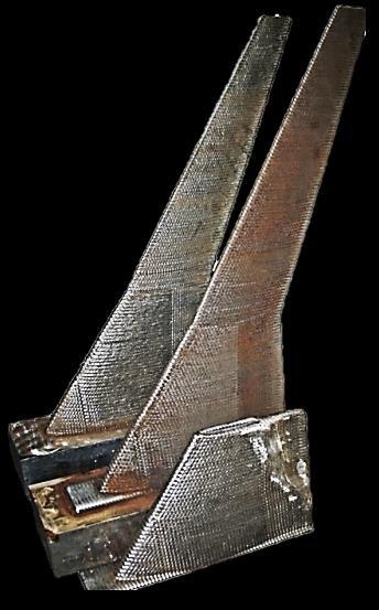
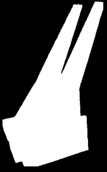
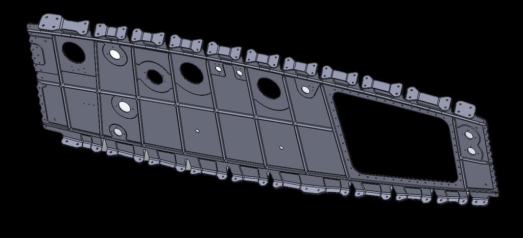
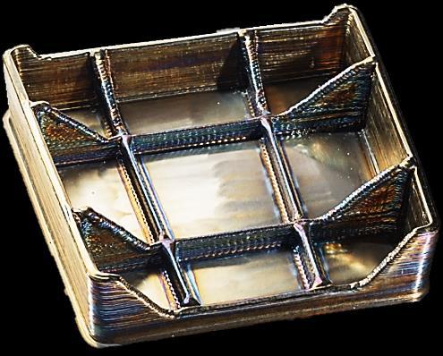
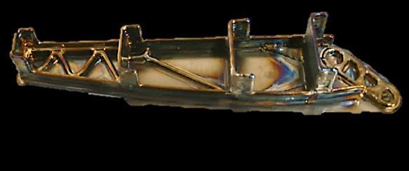
8 WAAM Ti-6Al-4V Landing Gear Rib ~ 20kg 0.7m BOMBARDIER


9 WAAM vs. Machining = Additive vs. Subtractive Ti-6Al-4V Landing Gear Rib ~ 20kg 0.7m BOMBARDIER
10 WAAM vs. Machining = Additive vs. Subtractive Raw Material BTF Cost Machined from Solid Billet 240 kg 12 23,650 $ + Machined Substrate + Wire 46 kg 2.3 7,300 $ Ti-6Al-4V Landing Gear Rib ~ 20kg 0.7m BOMBARDIER


11 System: Open Robot Cell Twin 7 Axis Robot System on Rails Customizable Tool Changer Welding Torch Machining MH Peening more Possible: Parts > 10 m

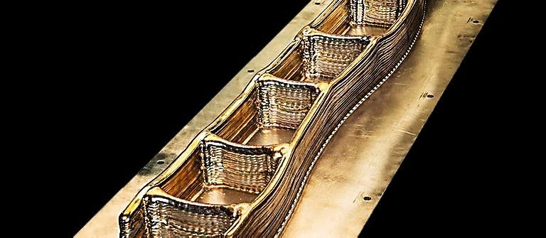
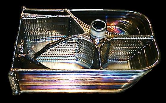
12 WAAM: Advantages Material / Time / Cost Saving Mechanical Properties Part Size > 10 m Ti-6Al-4V demonstrator components


13 Issue A: Grain Growth Large columnar grains Anisotropic properties Potential not fully exploit

14 Issue B: Residual Stress and Distortion Constant tensile stress in wall 4 Unbalanced stress condition Distortion σ x tensile Substrate
15 Issues How big are the Issues? A: Microstructure Mechanical Properties B: Residual Stress Distortion
")
16 A: Microstructure: Cross Section of Ti-6Al-4V Wall Liquid β Weld Pool Bottom = 1650 C 22 mm 6 mm β-transus = 1000 C Band (HAZ) Substrate
17 A: Microstructure: Minimum Mechanical Properties Ti-6Al-4V Cast Wrought Plate WAAM Z WAAM X AMS 4928 ASTM F Z 855 X Z 950 X Z 14 X Yield [MPa] Ultimate [MPa] Elongation [%]
18 B: Out-of-Plane Distortion σ res σ res clamped unclamped L = 400 mm D = 7mm
19 Solution Idea: Induce compressive strain + Heat Treatment How: Cold Inter-Pass Rolling

20 Vertical Inter-Pass Rolling

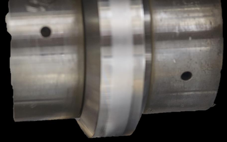
21 Rolling on Microstructure cold-induced compressive strain


22 Rolling on Microstructure d 100 μm Q Stored Mechanical Energy 1650 C β-transus 1000 C


23 Isotropic!!! Isotropic!!! Rolling on Microstructure: Improve Mechanical Properties Cast Wrought Plate WAAM as-deposited WAAM optimised β Rolling Yield [MPa] Ultimate [MPa]


24 Rolling: Improves Distortion D Transverse deformation must be suppressed control 50 kn 75 kn
25 Solution Rolling History Force Initial application: Rolling Butt Welds Transfer to: Vertical Rolling on WAAM


26 Solution Rolling Next Steps D 1 = 200 mm D 2 = 150 mm Pinch Rolling Planned: 2016 Performed: 2016
27 Distortion D [mm/400 mm lenght] Reduction in Distortion Residual Stress Plot 200 mm 150 mm Rolling Load [kn]


28 Longitudinal Residual Stress σ xx : Contour Method (M. Roy - Manchester University) Stress Plot Line 130 kn Side Rolled (no residual distortion)
29 Longitudinal Residual Stress [MPa] substrate Longitudinal Residual Stress σ xx : Neutron Diffraction (J. Hönnige - ISIS) Contour Method (M. Roy - Manchester University) Distance above Substrate [mm]
30 Longitudinal Residual Stress [MPa] substrate Longitudinal Residual Stress σ xx : Neutron Diffraction (J. Hönnige - ISIS) Contour Method (M. Roy - Manchester University) ND before Rolling Distance above Substrate [mm]
31 Longitudinal Residual Stress [MPa] substrate Residual Stress: Neutron Diffraction ISIS) Contour Method (Manchester University) ND after Rolling CM after Rolling ND before Rolling Distance above Substrate [mm]
32 Lab Scale


33 Real Candidate Parts? 0.7 m 2.64m 1.2 m 0.5 m 0.8 m 0.8 m 1.7 m 2.5m 0.7 m 2.5 m
34 Rolling Assisted WAAM CNC Milling & FSW Machine Integrated WAAM System


35 Rolling Assisted WAAM Wire Feeder and Spool Tool Holder Roller Torch Shield


36 Rolling Assisted WAAM Max. Working Envelope: 14 x 6 x 2.5 ft.

37 Rolling Assisted Wire + Arc Additive Manufacture of Meter-Scale Aerospace Components Large Scale Near Net Shape High Performance Structural Components j.honnige@cranfield.ac.uk
38 Control of Residual Stress, Distortion and Mechanical Properties in WAAM Ti64 Parts Jan Roman Hönnige Welding Engineering and Laser Processing Centre