Investigation of Arc and High Energy Welding Processes Applied to Advanced High Strength Steels
|
|
|
- Kenneth Williams
- 5 years ago
- Views:
Transcription
1 Investigation of Arc and High Energy Welding Processes Applied to Advanced High Strength Steels Donald F. Maatz, Jr. RoMan Engineering Services
2 Presentation Agenda Project Background Project Plan and Execution Data and Results Conclusions
3 Project Background - Objective Demonstrate technical feasibility of the weld processes for selected AHSS materials for: Lightweight Frame components Lightweight Front Structure components Evaluate manufacturability of Light Weight Frame joint designs Develop welding parameters and/or procedures for selected advanced weld processes
4 Project Background - Objective The Goal Parameters derived from this project to be applied to the actual prototype build phase of the various programs supported by the Structural Welding Sub-Group
5 Project Background - Team General Motors Corp. Daimler Chrysler Corp. Ford Motor Company J. Bohr W. A. Marttila A. Joaquin J. F. Quinn B. Patel A. Wexler C. Chen E. Pakalnins B. Clark M. Polon I. Accorsi A. Ray Steel Suppliers Industry Partners Auto/Steel Partnership M. Kuo (Mittal Steel) Fraunhofer Institute M. Bzdok M. Tumuluru (USS) RoMan Engineering P. Villano A. Lee (Dofasco) U. of Toledo T. Natale (AK Steel) J. Dolfi
6 Project Background Structure Joining Technologies Team SWSG Team Supplier A SWSG OEM Expert Sub-Group ( members) Contractor Supplier B Supplier C
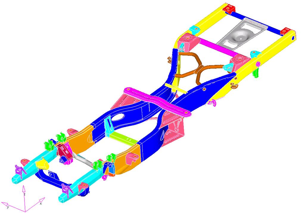
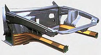
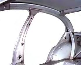
7 Project Background - Applications
8 Project Plan Processes and Materials Welding Processes GMAW Pulsed DC GMAW AC Laser YAG Hybrid YAG / GMAW Hybrid YAG / Plasma Selected Materials HSLA 0 (HDG, Bare) DP600 (HDG, Bare) DP800 (Galvanneal) DP980 (Galvanneal)


9 Project Plan GMAW (AC & DC) OTC DC Turbo Pulse 0 OTC AC MIG 00

10 Project Plan Laser Welding Rofin DY0 YAG laser Gantry locomotion No filler addition Penetration lap joints

11 Project Plan Laser/Plasma Hybrid Kuka robotic locomotion Thermal Arc power source Rofin DY0 YAG laser No Filler Addition Penetration Lap joints
12 Project Plan Test Matrix Stack-up Number Top Sheet Bottom Sheet Process Evaluation Filler Metal Utilized 8 9.mm DP600 Bare.mm DP600 HDG.8mm HSLA0 HDG.8mm DP980 GA.0mm DP800 GA.mm DP800 GA.7mm DP780 GA.mm DP600 Bare.mm HSLA Bare.mm HSLA Bare.8mm DP980 GA.0mm DP800 GA.87mm DP780 GA.87mm DP780 GA AC,DC,LS,LM,PL AC,DC,LS,LM,PL AC,DC,LS,LM,PL AC,DC,LS,LM,PL AC,DC,LS,LM,PL AC,DC,LS,LM,PL AC,DC,LS,LM,PL 70 ksi 70 ksi 70 ksi 70 ksi 70 ksi 70 and 90 ksi 70 and 90 ksi
13 Project Plan Weld Acceptance Criteria Criteria Source Document Derivative SWSG Requirement Porosity - Internal Porosity - Surface GM GM 90M, 99 Cross-section <= % of total area GM GM 90M, 99 < % Weld Length A/SP SWSG. +/-.0mm Weld Interface A/SP SWSG >= 7% of thinner metal, then.0 mm Weld Surface A/SP SWSG Report only, no requirement Weld Location A/SP SWSG As specified +/-.0mm Burn-through (Hole) Under Cut (Maximum) Convexity Penetration GM Not allowed GM 90M, 99 Chrysler PS-909 % of thinnest metal 00, NOV 6, CHG B Not addressed Chrysler PS-909 >= 0% into second metal 00, NOV 6, CHG B
14 Project Plan Sample Design Tensile Shear Sample mm mm mm mm Figure : Sample for tensile shear. Shims were placed at each end to keep the fatigue load applied along a line through the plane of the weld.
15 Project Plan Sample Design Typical Impact Coupon Shape and Dimensions 0mm 60 Deg. Bend (6mm Radius) Overlap 0.8mm Typical fillet weld location. Weld is " long and is centered on the coupon. 76mm Typical Lap weld location. Weld is " long and is centered on the coupon. 0mm Coupon Size (Before Bending) is 78mm x 76mm
16 Project Plan Procedure Approval Sample weldments for each process, stack-up, and filler combination were submitted for approval to the Weld Sub-Group prior to test sample completion. Preliminary reports included: Cross section Photo of completed weld Tensile Data
17 Data and Results - Laser LASER AVERAGE IMPACT ENERGY (J) Avg Impact Energy (J) Laser Welding Impact and Tensile Shear Data LASER AVERAGE PEAK LOAD (kn) 0.00 IM-0 IM-0 IM-0 IM-0 IM-0 IM-08 IM Metal Stackups Avg Peak Tensile Shear (kn) TS TS TS-0 00-TS TS TS TS-09 Metal Stackups
 VICKERS HARDNESS CHART 0 VICKERS HARDNESS")
 VICKERS HARDNESS CHART 0 00 60 0 80 6 0 67 6 0 6 6 9 0 00 98 9 6 6 0 96 99 00 9 90 60 0 6 8 0 DISPLACEMENT (mm) BM")
18 Data and Results Microhardness Microhardness Traverse Reporting VICKERS HARDNESS CHART VICKERS HARDNESS (HV) DISPLACEMENT (mm) VICKERS HARDNESS CHART 0 VICKERS HARDNESS (HV) DISPLACEMENT (mm) HAZ HAZ WELD BM BM HAZ HAZ WELD BM BM Laser VICKERS HARDNESS (HV) VICKERS HARDNESS CHART DISPLACEMENT (mm) BM WELD BM GMAW
19 Data and Results Tensile-Shear Tensile Shear Strength Comparison GMAW (DC) Laser-GMAW Laser (70) 8 (90) 9 (70) 9 (90) 8 (70) 8 (90) 9 (70) 9 (90) Metal Stackups Avg Tensile Shear Load (kn)
20 Conclusions ( of ) Processes w/ filler metal demonstrated improved mechanical properties compared to those without 60 Tensile Shear Strength Comparison Avg Tensile Shear Load (kn) Laser GMAW (DC) (70) 8 (90) 9 (70) 9 (90) 8 (70) 8 (90) 9 (70) 9 (90) Laser-GMAW Metal Stackups
21 Conclusions ( of ) Material strength and/or thickness had no influence on laser welded joint strength 60 Tensile Shear Strength Comparison Avg Tensile Shear Load (kn) Laser GMAW (DC) (70) 8 (90) 9 (70) 9 (90) 8 (70) 8 (90) 9 (70) 9 (90) Laser-GMAW Metal Stackups
22 Conclusions ( of ) Filler material tensile strength had no direct correlation with weld strength for this study 60 Tensile Shear Strength Comparison Avg Tensile Shear Load (kn) Laser GMAW (DC) (70) 8 (90) 9 (70) 9 (90) 8 (70) 8 (90) 9 (70) 9 (90) Laser-GMAW Metal Stackups

23 Conclusions ( of ) Zinc coated materials demonstrated high levels of porosity when welded without an engineered gap
24 Thank You