Localized Top of the Line Corrosion in Marginally Sour Environments
|
|
|
- Christian Miles
- 5 years ago
- Views:
Transcription
1 Paper No Localized Top of the Line Corrosion in Marginally Sour Environments Najmiddin Yaakob 1, Fernando Farelas, Marc Singer, Srdjan Nesic, David Young, Institute for Corrosion and Multiphase Technology Department of Chemical & Biomolecular Engineering Ohio University, Athens, OH Localized corrosion has been reported to happen in sour environments via a number of mechanisms. Some of these mechanisms are well understood and described (elemental sulfur, oxygen ingress) while considerable uncertainties still remain on the influence of other environmental parameters (FeS polymorphs, organic acid and etc). This paper addresses the occurrence of localized corrosion at the top of the line in a condition that is typically described as marginally sour : CO 2 environments with low H 2 S concentrations. Little has been published on this topic so far and the mechanisms involved are not well defined. This research presents a systematic study of the effect of low H 2 S concentrations on corrosion of an API 5L X65 carbon steel exposed to top of the line conditions. Special emphasis is given to the transition between sweet and sour corrosion and how it relates to localized corrosion. Experiments were performed for 7 days at 1 bar total pressure in a CO 2 /H 2 S environment. The H 2 S partial pressure was varied from 0 to 0.15 mbar at two different gas temperatures (40 o C and 60 o C). Corrosion rate measurements and surface analyses revealed extensive localized corrosion at H 2 S partial pressure below 0.08 mbar, being more severe at a gas temperature of 40 o C than at 60 o C. No localized corrosion was observed without H 2 S or at H 2 S partial pressure above 0.08 bar in the conditions tested. The occurrence of localized corrosion is speculated to be due to the formation of a non-homogenous corrosion product layer and to the unfavorable balance between the rates of protective layer formation and undermining by corrosion. Keywords: sour, top of the line corrosion, H 2 S, water condensation rate, localized corrosion INTRODUCTION Top of the Line Corrosion (TLC) mechanisms of sweet (CO 2 dominated) and sour (H 2 S dominated) environments are different. However, one significant and still unresolved challenge is to define the threshold of H 2 S level for which the TLC mechanism transitions from sweet to sour. Dunlop, et al., 1 and Smith 2 reported a CO 2 /H 2 S ratio of 500 as a reference point for the transition between sweet and sour corrosion. They claim that if the ratio is higher than 500, it is presumed that iron carbonate (FeCO 3 ) should be dominant, if lower than 500, iron sulfide (FeS) should form. This threshold corresponds to a situation where the concentrations of aqueous H 2 CO 3 and aqueous H 2 S are approximately the same at room temperature. This ratio is very sensitive to thermodynamic data, such as the heat of formation ( H f ) and FeCO 3 Gibbs free energy ( G) for FeS and FeCO 3. Dunlop used values obtained in Currently at Universiti Teknologi MARA Malaysia 1
2 which are now obsolete. In addition, this rule of thumb cannot be reliably applied outside the range of conditions tested by the original authors (25 o C). It is consequently not recommended to use this as an engineering tool to predict corrosion in the field and can only act as a rough guideline to investigate the transition point between sweet and sour environments. However, some alternative methods can be suggested to address the issue of whether, or not, a corrosion environment can be deemed sweet, sour or marginally sour. The first one relates to using phase identification of formed corrosion product layers. In sweet (CO 2 ) environments, iron carbonate (FeCO 3 ) should be found as the corrosion product. In fully sour (H 2 S) environments, only iron sulfide has been proven to form due to its rapid formation kinetics. This method would indeed yield accurate characterization of the environment but can only be used as a post-analysis tool. Another possible method involves the use of Pourbaix diagrams to predict the equilibrium phase for resultant corrosion products given particular conditions, such as partial pressure of CO 2 or H 2 S, ph, and temperature. Determining which of the corrosion product layers are thermodynamically favored could be indeed very useful but the method may not be able to identify the formation of kinetically favored species such as mackinawite. Another approach is to try and improve the approach suggested by Dunlop, et al., using the ratio of partial pressure of CO 2 and H 2 S (pco 2 /ph 2 S), however, it is likely that there is no universal validity of this approach and that it could not be easily extrapolated to a wide range of conditions. The task is indeed complex and the present work does not try to offer a definite answer. However, data reported herein may provide additional information that could lead to a better understanding of how to define sweet, sour and ultimately marginally sour systems. To date, there have been few publications that have dealt with marginally sour environments, with only some related to TLC. Brown, et al., 3 reported localized corrosion rates as high as 30 mm/y in 10 mbar H 2 S (1500 ppm) in steel specimens exposed to bottom of the line conditions. R. Nyborg et al. 4 conducted TLC experiments with 2 mbar (200 ppm) H 2 S, 10 bar CO 2, 500 ppm acetic acid and 25 C, and reported the formation of a porous FeS layer ( µm thick). However, close to the steel surface a protective FeCO 3 layer was formed. The authors claimed sulfide depletion close to the metal surface resulted in the formation of FeCO 3. Furthermore, the measured TLC rate was higher in comparison to that predicted in the sweet TLC conditions without H 2 S. Other research performed by Li, et al., 5 in marginally sour TLC (1000 ppm H 2 S, 7 bars CO 2, T steel = 40 C) showed that both FeS and FeCO 3 could form simultaneously on the steel surface. The author reported similar findings as those in sweet environments, where higher water condensation rates led to higher TLC rates because they reduced the supersaturation of FeCO 3, leading to a less protective corrosion product layer. In the research reported herein, the H 2 S partial pressure was varied from 0 to 0.15 mbar at approximately 1 bar CO 2 and two different gas temperatures (40 C and 60 C). These gas temperatures were selected in order to give a significant temperature different between the cooled steel and the gas that would promote the condensation process. EXPERIMENTAL PROCEDURE A 2 L glass cell setup was used to conduct experiments at atmospheric pressure, as shown in Figure 1. Two cylindrical X65 carbon steel specimens (3.2 cm diameter and 1.2 cm thickness) were coated on the sides and bottom with an electrically insulating polymer coating, leaving an exposed area of 8 cm 2 and were flush mounted on the lid of the glass cell. Cooling coils were placed around the specimen holders and water was circulated therein to facilitate condensation on the specimen surface. A hot plate was used to heat the solution in order to achieve the desired gas temperature. One specimen was used for weight loss corrosion rate determination and the other for cross-section analysis. Condensed water was collected in the collection cup for determination of ferrous ion concentration, condensation rate, and ph measurement. The ph of the condensed water and the bottom solution were measured in situ. Prior to each experiment, the weight loss specimens (made from X65 carbon steel) were polished with silicon carbide abrasive papers of up to 600 grit, using isopropyl alcohol as coolant,. The specimens were then flush mounted on the glass cell lid using a specially designed holder. The bottom of the cell 2
3 solution consisted only of deionized water deoxygenated for two hours by purging with nitrogen gas. H 2 S and CO 2 were then mixed using a rotameter to achieve the desired concentration of H 2 S and introduced into the glass cell. The gas mixture was continuously sparged in the glass cell throughout the experiments. The concentration of H 2 S in the gas phase was measured by using a colorimetric gas detector tube every two days to confirm that it remained constant. Effluent gas was passed through a bed of activated carbon prior to being released into a combustion system. The water condensation rate was measured every day by collecting and measuring the volume of condensed water over specific durations. Thus, by knowing the volume of condensed water, the duration, and the surface area of the specimen, the water condensation rate can be calculated (values are shown in the test matrices below). The steel temperature was measured every day by placing a thermocouple at the back side of the steel specimen, facing outward from the glass cell lid. Upon removal from the system, specimen surfaces were rinsed with isopropyl alcohol, dried, and stored in desiccators for further surface analysis. The ASTM G1 standard was followed to remove the corrosion products and determine the corrosion rate by weight loss. 6 Half of the specimen were generally used for weight loss measurements, the others were preserved for further corrosion product evaluation. Scanning electron microscopy (SEM) was used to study the corrosion product morphology while energy dispersive X-ray spectroscopy (EDS) microanalysis was used for chemical analysis. Prior to SEM/EDS, specimens were sputter coated with palladium. In addition, after removal of the corrosion product layer, profilometry measurements were conducted using a high resolution optical microscope in order to characterize the topography, e.g., pitting, due to corrosion, in accordance to the ASTM G The Tables 1 and 2 below list the test conditions selected for the study. They are divided in two main parts: Part A: Marginally sour experiments performed at 40 C Part B: Marginally sour experiments performed at 60 C Table 1: Test matrix part A; marginally sour TLC at 40 C Parameter TLC in mixed CO 2 /H 2 S environment Total pressure (bar) 1 pco 2 (bar) 0.93 Gas temperature ( C) 40 temperature ( C) 28 ± ± ± ± 1 28± 1 Condensation rate 0.25 ± 0.25 ± (ml/m ± ± ± 0.06 /s) ph 2 S (mbar) Test duration 7 days Table 2: Test matrix part B; marginally sour TLC at 60 C Parameter TLC in mixed CO 2 /H 2 S environment Total pressure (bar) 1 pco 2 (bar) 0.8 Gas temperature ( C) 60 Temperature ( C) 43.0 ± ± ± ±2.4 40±1.9 Condensation rate (ml/m 2 /s) 1.47 ± ± ± ± ±0.25 ph 2 S (mbar) Test Duration 7 days 3
 Corrosion rate analysis EXPERIMENTAL RESULTS AND DISCUSSION Comparisons of general corrosion rate, obtained from weight loss measurement, and pit penetration")
4 specimen holder Gas inlet Cooling coil Gas outlet ph probe Heater Sampling port Condensation collection cup Scrubber Figure 1: Glass cell experimental set up for marginally sour TLC experiments. (Images courtesy of Cody Shafer, ICMT) Corrosion rate analysis EXPERIMENTAL RESULTS AND DISCUSSION Comparisons of general corrosion rate, obtained from weight loss measurement, and pit penetration rate from the depth of the deepest pit found by profilometry analysis, are plotted for experiments performed at 40 C as shown in Figure 2. Overall, the uniform corrosion rate decreased with increasing H 2 S partial pressure, from 0 to 0.15 mbar. The uniform corrosion rate was reduced from 0.38 mm/yr at 0 mbar H 2 S to 0.16 mm/yr at 0.15 mbar H 2 S. The reduction of TLC rate with increasing H 2 S concentration has also been reported and explained by other authors. 8 Interestingly, the presence of mbar and 0.03 mbar H 2 S resulted in pit penetration rates of 2.3 mm/y and 4.0 mm/y, respectively. At these critical H 2 S partial pressures, the pitting ratio, which is the ratio between pit penetration rate and general corrosion rate, were calculated to be 9 and 16, at mbar and 0.03 mbar H 2 S, respectively. According to an internal procedure developed to evaluate pitting, any ratio above the value of 5 would constitute a clear case of localized corrosion. 9 Thus, from this observation, it is obvious that steel specimens exposed to the 0.03 mbar H 2 S environment suffered the highest localized corrosion rate. However, as the H 2 S partial pressure was increased to 0.08 and 0.15 mbar, no localized corrosion was observed, as only general corrosion was detected. 4
5 Figure 2: Comparison of corrosion rates from weight loss measurement and pit penetration rate Part A (gas temperature = 40 C) At gas temperature of 60 C, the same method of corrosion rate analysis was performed as described above, this time for 0, 0.015, 0.03, 0.08, and 0.15 mbar H 2 S. The highest general corrosion rate was 1.1 mm/yr when no H 2 S was present. The general corrosion rate decreased with increasing H 2 S partial pressure, as shown in Figure 3. At and 0.03 mbar H 2 S, no significant difference in general corrosion rate was observed; being 0.65 mm/yr in each case. However, the pit penetration rate was not as high as observed in the lower temperature test condition (part A, Figure 2). The pit penetration rates were calculated to be 1.9 and 1.4 mm/y, which result in lower pitting ratios of 2.8 and 2.2, at mbar and 0.03 mbar H 2 S, respectively. As stated above, according to the same internal procedure developed to evaluate pitting, any pitting ratio above the value of between 2 and 5 would constitute a possible case of localized corrosion. Thus, the results obtained here could not be confidently described as localized attack. This type of attack was previously described as localized uniform corrosion, which is a well known scenario in TLC. 10 As the H 2 S partial pressure increased to 0.08 mbar and 0.15 mbar, no localized corrosion was observed as only a general corrosion rate of 0.4 mm/yr was determined for both conditions. Overall, the pit penetration rate at 60 C was lower when compared to that at 40 C, with the most significant difference seen at 0.03 mbar H 2 S. This can be ascribed to kinetic effects. The higher temperature increased the rate of formation of the FeS layer inside the initiated pits and protected the steel from further localized attack. However, the general corrosion rate at 60 C was higher as compared to that seen at 40 C. This can be explained by the fact that at 60 C a higher water condensation rate was observed. This limits the supersaturation with respect to aqueous species required for formation of both FeCO 3 and FeS, phases that can confer a degree of protection against corrosion. This is similar to TLC behavior seen in sweet environments; increased water condensation rate (from ml/m 2 /s to 1.5 ml/m 2 /s) leads to a higher TLC rate. 5
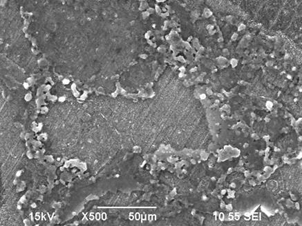
6 Figure 3: Comparison of corrosion rate from weight loss measurement and pit penetration rate Part B (gas temperature = 60 C) Corrosion product analysis After each experiment, corrosion product layers for each H 2 S concentration were analyzed using SEM and compared, as shown in Figure 4 for part A (gas temperature 40 C). At 0 mbar H 2 S, no FeCO 3 crystals were observed and the steel surface and chemical analysis (EDS) revealed residual alloying elements (Cu, Fe, Mo, C & Cr) which is indicative of the presence of Fe 3 C. At and 0.03 mbar H 2 S, the corrosion product layer retained polishing marks from the specimen preparation process. This could be an indication that this is the first FeS layer to form by a fast precipitation at the original steel surface. It is important to note that some spots where the layer failed to form were found. These failure locations are most likely the spots where localized corrosion initiated. In addition to alloying elements, the EDS analysis shows the presence of sulfur, which suggests the presence of FeS on the steel surface. It could also be seen that the failed FeS layer was most likely a result of undermining corrosion that occurred beneath the FeS layer. At this point, the undermining corrosion rate was very high and the precipitation rate was low; this is indicative of an increased likelihood of localized corrosion. At higher H 2 S partial pressure ( mbar), distinct FeS layers were observed where the second FeS layer formed on top of the initial FeS layer (one with polishing marks). At higher H 2 S partial pressure, the scaling tendency was increased and led to FeS layer precipitation that conferred a degree of protection to the steel from corrosion. No failure in the FeS layer was observed under these conditions. 6
 (0.")
 (0.")


7 (0 mbar H2 S) (0.015 mbar H 2 S) (0.03 mbar H 2 S) (0.08 mbar H 2 S) 7


8 (0.15 mbar H 2 S) Figure 4: SEM/EDS analysis with corrosion product layer -Part A (gas temperature = 40 C) For gas temperature 60 C, the surface profile analysis was also performed using SEM/EDS. Comparisons at each H 2 S partial pressure, from 0 mbar to 0.15 mbar H 2 S, are shown in Figure 5. At 0 mbar H 2 S, observed morphologies and compositional analysis support the presence of FeCO 3. Polishing marks could still be seen at mbar H 2 S between crystals and, from EDS analysis, sulfur was present, indicative of the formation of FeS. This is also an indication that a thin FeS layer rapidly precipitated on the original steel surface. At and 0.03 mbar H 2 S, fewer corrosion product failures were observed, as compared to the results obtained at the lower temperature of 40 C. Furthermore, at higher H 2 S partial pressure ( mbar), a distinct second layer of FeS is observed on top of the initial one implying a more intense and sustained rate of precipitation. Overall analysis by EDS showed the presence of FeS on the steel surface at 0.015, 0.03, 0.08, and 0.15 mbar H 2 S. (0 mbar H 2 S) (0.015 mbar H 2 S) 8
 Figure 5: SEM/EDS analysis with corrosion product layer - Part B (gas temperature = 60 C) Cross-section analysis specimens that were not used for")


9 (0.03 mbar H 2 S) (0.08 mbar H 2 S) (0.15 mbar H 2 S) Figure 5: SEM/EDS analysis with corrosion product layer - Part B (gas temperature = 60 C) Cross-section analysis specimens that were not used for weight loss determination were mounted in epoxy, crosssectioned, polished and the corrosion product layer was analyzed using SEM. The comparisons of the cross-section for specimens exposed to various H 2 S partial pressure are shown for gas temperature 40 C, in Figure 6. At 0 mbar H 2 S, the corrosion product layer was very thin, only 1-2 µm thick, with no obvious pitting initiation. However, as the H 2 S partial pressure was increased to and 0.03 mbar H 2 S, pits were observed as deep as 50µm. As previously explained in the corrosion rate analysis, no localized corrosion was observed at higher H 2 S partial pressure ( mbar). These findings are supported by the cross-section images in which the steel was fully covered and protected by a thicker FeS layer. 9
 Figure 6: Cross-section analysis with corrosion product layer - Part A (gas temperature = 40 C) The same cross-sectional analysis procedure was also")


10 (0 mbar H 2 S) (0.015 mbar H 2 S) (0.03 mbar H 2 S) (0.08 mbar H 2 S) (0.15 mbar H 2 S) Figure 6: Cross-section analysis with corrosion product layer - Part A (gas temperature = 40 C) The same cross-sectional analysis procedure was also completed for specimen exposed at gas temperature 60 C. Specimens were mounted in epoxy, cross-sectioned, polished, and the corrosion product layer analyzed using SEM. At 0 mbar H 2 S, the corrosion product layer was thicker as compared to that seen at 40 C; 5-6 µm thick with no pitting as shown in Figure 7. However, as the H 2 S partial pressure increased to mbar and then 0.03 mbar, the specimens suffered more from general rather than localized corrosion since, compared to the results obtained at 40 C, there were no deep pits. The pits which did formed were wide and shallower. This finding supported the corrosion rate analysis because, at this point, the pitting ratio was below 3; this could not be considered as definitive localized corrosion. EDS analysis inside the pits showed traces of FeS. As was also the case at 40 C, no pitting was observed at higher H 2 S partial pressure ( mbar). The steel was fully covered with a thin FeS layer. It is noteworthy that residual alloying elements were less likely to be present in the corrosion product layer as the tested H 2 S partial pressure increased. 10
 Figure 7: Cross-section analysis with corrosion product layer - Part B (gas temperature = 60 C) Surface profilometry Profilometry analysis was performed on the steel")


11 (0 mbar H 2 S,) (0.015 mbar H 2 S) (0.03 mbar H 2 S) (0.08 mbar H 2 S) (0.15 mbar H 2 S) Figure 7: Cross-section analysis with corrosion product layer - Part B (gas temperature = 60 C) Surface profilometry Profilometry analysis was performed on the steel surface after removal of the corrosion product layer in order to fully characterize the occurrence of localized corrosion. At 0 mbar H 2 S, no localized corrosion was observed; only surface roughening due to general corrosion was measured. As the partial pressure of H 2 S was increased to mbar and 0.03 mbar, pitting as deep as 45 and 80 µm, respectively, was observed. The highest pit penetration rate was calculated to be 4.2 mm/y at 0.03 mbar H 2 S, as shown in Figure 8. No localized corrosion was observed at higher H 2 S partial pressure ( mbar), as only surface roughening resulting from general corrosion was measured The profilometry analysis supported the results obtained previously; localized corrosion was initiated at and 0.03 mbar H 2 S, while only general corrosion was observed at higher H 2 S partial pressure ( mbar). 11


12 0 mbar H 2 S mbar H 2 S 0.03 mbar H 2 S 0.08 mbar H 2 S 0.15 mbar H 2 S Figure 8: Surface profilometry analysis after removal of corrosion product layer Part A (gas temperature = 40 C) Similarly for at 60 C, profilometry was used for measurement of pit depth on the steel surface after removal of the corrosion product layer. Comparisons for various H 2 S partial pressures are shown from Figure 9. At 0 mbar H 2 S there was again no localized corrosion detected, as only surface roughening from general corrosion was observed. As the H 2 S partial pressure was increased to mbar and then 0.03 mbar, pitting as deep as 34 and 30µm, respectively, was observed. As mentioned previously, the pit depth was not as deep as that observed at 40 C. The highest pit penetration rate was calculated to be 1.8 mm/y and 1.6 mm/y with mbar and 0.03 mbar H 2 S, respectively. Furthermore, the pit population is considered to be high for both mbar and 0.03 mbar H 2 S in accordance with ASTM G Again, similar to at 40 C, no localized corrosion was found at mbar H 2 S. 12

 TLC conditions.")
.")

, no localized corrosion was seen.")
13 0 mbar H 2 S mbar H 2 S 0.03 mbar H 2 S 0.08 mbar H 2 S 0.15 mbar H 2 S Figure 9: Surface profilometry analysis after removal of corrosion product layer Part B (gas temperature = 60 C) CONCLUSIONS No localized corrosion occurred in sweet (CO 2 ) TLC conditions. A non-homogenous FeS surface layer coverage occurred at marginally sour conditions i.e. at low H 2 S partial pressure ( mbar). This led to distinctive protected and not protected regions on the steel surface and high localized corrosion rates - severe pitting. As the partial pressure of H 2 S increased ( mbar), no localized corrosion was seen. This is due to the faster kinetics of FeS precipitation and formation of a more homogenous protective layer, which overpowered corrosion. A similar effect was seen at higher temperature of 60 C when compared to 40 C. 13
14 ACKNOWLEDGEMENTS The authors would like to acknowledge the financial support from the following companies and organizations: Apache, BHP Billiton, BP, Chevron, ConocoPhillips, M-I-SWACO, PETRONAS, PTTEP, Woodside, Talisman, Universiti Teknologi MARA and Ministry of Higher Education Malaysia. REFERENCES 1. A. Dunlop, H. Hassell, and P. Rhodes, Fundamental Considerations in Sweet Gas Well Corrosion, in Proc. Corrosion, Houston, TX, 1987, paper no S. N. Smith, Discussion of the History and Relevance of the CO 2 /H 2 S Ratio, in Proc. Corrosion, Houston, TX, 2011, paper no B. Brown and S. Nesic, Aspects of Localized Corrosion in an H 2 S/CO 2 Environment, in Proc. Corrosion, Houston, TX, 2012, paper no. C R. Nyborg, A. Dugstad, and T. G. M. Ret, Top of Line Corrosion with High CO 2 and Traces of H 2 S, in Proc. Corrosion, Houston, TX, 2009, paper no C. Li, W. Sun, S. Ling, and J. L. Pacheco, Experimental Study of Top of Line Corrosion in Slightly Sour Environments, in Proc. Corrosion, Houston, TX, 2012, paper no. C ASTMG1-03, Standard Practice for Preparing, Cleaning and Evaluating Corrosion Test, ASTM, Phidelphia,PA, pp , ASTMG46-94, Standard Guide for Examination and Evaluation of Pitting Corrosion, ASTM, Phidelphia,PA, pp. 1 7, A. Camacho, M. Singer, B. Brown, and S. Nesic, Top of the Line Corrosion in H 2 S/CO 2 Environments, in Proc. Corrosion, Houston, TX, 2008, paper no M. Singer, A. Camacho, B. Brown, and S. Nesic, Sour Top of the Line Corrosion in the Presence of Acetic Acid, in Proc. Corrosion, Houston, TX, 2010, paper no M. Singer, Study and Modeling of the Localized Nature of Top of Line Corrosion, PhD dissertation, Russ College of Engineering., Dept of Chemical Engineering., Ohio University,