Process, Microstructure & Tooling
|
|
|
- Amos Johnston
- 5 years ago
- Views:
Transcription
1 improving manufacturing by simulation: Process, Microstructure & Tooling Dr Brian Miller Sales & Marketing Director
2 Overview Formed in 1980 as Finite Elements Ltd clients Member of Wilde Group of 70+ employees and 10m + turnover Value Added Reseller for ANSYS, Autodesk Moldflow, DEFORM & ReliaSoft ISO 9001:2008 Approved Quality Management System On UK-steering committee for NAFEMS and involvement with many industry associations.


3 Probability Wilde Analysis FEA CFD Reliability 0 L S Value
4 Benefits of Simulation In Design Improved product performance optimised Less R&D lead time, costs and prototypes Lighter reduced material and energy costs More reliable, less requirement for replacement Enables design for manufacture In Manufacture Less shop trials Reduced scrap rates Less material waste (flash, swarf, runners) Improved quality & material performance


5 Applications in all Engineering Fields


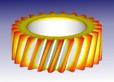
6 Manufacturing Simulation Topics (POLYFLOW) Blow Moulding, Extrusion & Other Polymer Processes Shape & tooling optimisation + initial property determination for structural analysis Plastic Injection Moulding (Unfilled + Fibre Filled) Shape & tooling optimisation + initial property determination for structural analysis Metal Forming + Heat Treatment + Microstructure Shape & tooling optimisation + initial property determination for structural analysis + multiple process chain


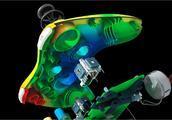
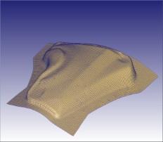
7 Process Modelling Design for Manufacture Example: Plastics Design Assess design Non-uniform thickness Poor draft angles / undercuts Complex and expensive Assess manufacturability Areas difficult/impractical to manufacture Courtesy: Autodesk

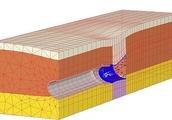
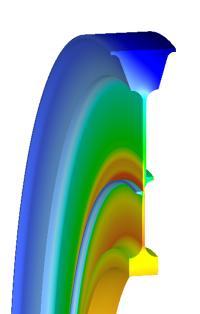
8 Microstructural Modelling Provides detailed information about the microstructure during thermo-mechanical processing. Opportunities to improve process design through understanding impact on material Courtesy: SFTC


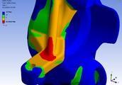
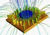
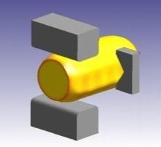
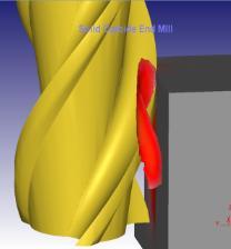
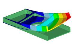
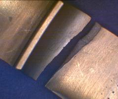
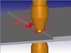
9 Tooling Analysis A carbide insert failed consistently in a high volume steel automotive part. DEFORM was used in 1996 to isolate the root cause - an axial tensile stress at the fracture initiation point. After redesign, the life was increased more that ten-fold for the first three stations in the progression.


 modify CAD")
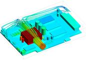
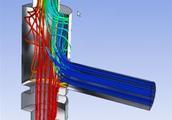
10 Virtual Prototyping of Blow Moulding CAD Design Process Simulation / Manufacturing Part Testing (Implicit / Explicit structural analysis) modify CAD modify process Fail PASS Courtesy: ANSYS

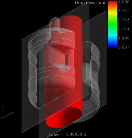
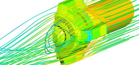
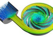
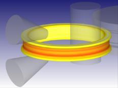
11 Blow Moulding Process Simulation Courtesy: ANSYS


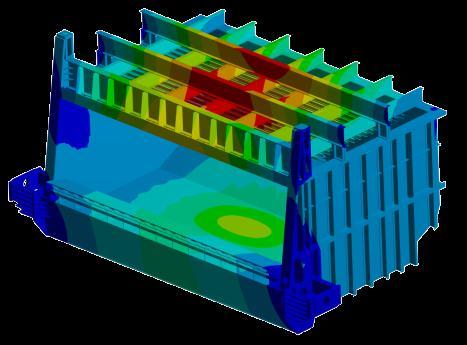
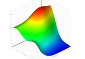
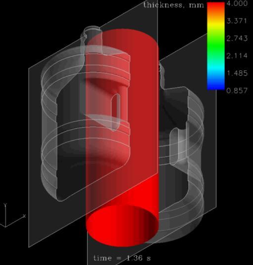
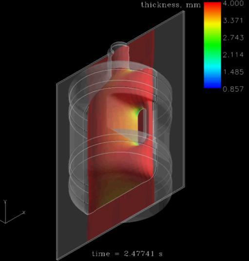
12 Location of Minimum Thickness Identification of location with smallest thickness. Would this virtual product satisfyingly pass the tests and behave properly under services? Courtesy: ANSYS


13 Effect of Variable Thickness uniform thickness variable thickness Top load - total deformation

14 Moldflow to Structural Analysis Primary stiffening cover, essential for the entire phone stiffness Courtesy: Autodesk
15 Moldflow to Structural Analysis Material PA, Zytel HTN53G50HSLR (DuPont) (50%Glass) restraints Vertical force Courtesy: Autodesk

16 Gate Location: Top Moldflow to Structural Analysis Gate location Fiber orientation Poor orientation in this area Courtesy: Autodesk

17 Gate Location: Bottom Moldflow to Structural Analysis Gate location Fiber orientation Good orientation in this area Courtesy: Autodesk

18 Gate Location: Mid Moldflow to Structural Analysis Gate location Fiber orientation Good orientation in this area Courtesy: Autodesk
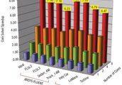
19 Deflection Comparison Deflections predicted by Moldflow for different fibre orientations compared to isotropic material Gate location Fiber orientation Max. deflection Bottom Good 4.95mm Mid Good 4.27mm Top Poor 5.29mm Isotropic material 3.45mm Courtesy: Autodesk

20 Stress Comparison Fully integrated analysis: s vonmises =35.9 MPa Traditional stress analysis: s vonmises =14.4 MPa Fully integrated analysis: s vonmises =80.1 MPa Traditional stress analysis: s vonmises =17.2 MPa Courtesy: Autodesk


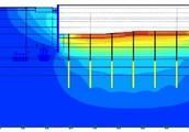
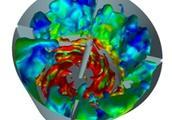
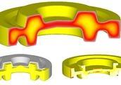
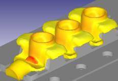
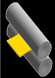
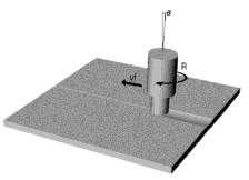
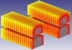
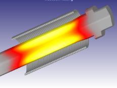
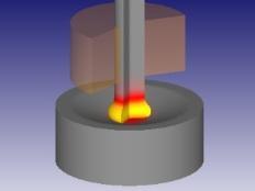
21 Typical Metal Forming Applications Hot forging Thread rolling Mechanical joining Cogging Machining Other applications Courtesy: SFTC


22 Typical Metal Forming Applications Hot forging Thread rolling Mechanical joining Cogging Machining Other applications Courtesy: SFTC

23 Typical Metal Forming Applications Hot forging Thread rolling Mechanical joining Cogging Machining Other applications Courtesy: SFTC
24 Typical Metal Forming Applications Hot forging Thread rolling Mechanical joining Cogging Machining Other applications Courtesy: SFTC

25 Typical Metal Forming Applications Hot forging Thread rolling Mechanical joining Cogging Machining Other applications Courtesy: SFTC

26 Typical Metal Forming Applications Hot forging Thread rolling Mechanical joining Cogging Machining Other applications Courtesy: SFTC

27 Typical Metal Forming Applications Hot forging Thread rolling Mechanical joining Cogging Machining Other applications Courtesy: SFTC


28 Integrated Process Modeling System Geometry Microstructure Anomalies Properties Residual Stress Cogging Forging Heat Treat Machining Spin Lifing Cogging Sequence Shape Ram Speed Cooling Rate Machining Sequences Mission Cycles Alloy Composition Design DOE Optimization Courtesy: SFTC
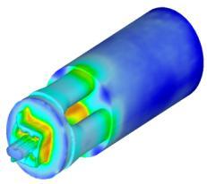
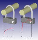
29 Machining Distortion A number of leading aero engine OEMs and disk manufacturers are managing residual stress and machining distortion on a production basis. Three dimensional capabilities are being developed as an ongoing effort. Courtesy: SFTC


30 Machining Distortion s l o w co o l fa s t q u e n c h residual stress after heat treatment residual stress after machining machining distortion (magnified 20X) Courtesy: SFTC

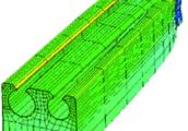
31 Machining Distortion Heat treat & machining distortion can be modeled in 2D as an axisymmetric model. Broaching is simulated using a 3D model. 2D 3D conversion can be used to sweep the geometry and interpolate the residual stress to a three dimensional model.


32 Metal Forming Simulation Future Forging Heat Treatment Mechanical Joining Machining Cogging Pull Test Casting Cold Forming Furnace Heating Inertia Welding Milling Life Extrusion Ring Rolling Induction Heating Spot Welding Machining Distortion Spin Testing Rolling Sheet Forming Resistance Heating Stir Welding Courtesy: SFTC
33 Summary Engineering analysis increasingly applied to both product design and also manufacture. In the most critical service applications, product optimisation spans multiple dissimilar processes. Simulating geometry through the manufacturing cycle is inadequate to accurately predict in-service performance. Prediction of internal properties (microstructure/ residual stress / fibre orientation) is required to simulate the part behaviour through a range of processes.

34 Thank You