Catalog 2009 TUFFALOY. Resistance Welding Products. Leader in the Industry Since 1937
|
|
|
- George Higgins
- 5 years ago
- Views:
Transcription


1 Catalog 2009 Resistance Welding Products Leader in the Industry Since 1937


2 table of contents ELECTRONICS STANDARD ELECTRODES RESISTANCE WELDING PRODUCTS The little man is now seventy years old. It was in 1937 that Welding Sales & Engineering Company of Detroit introduced a new line of resistance welding alloys tradenamed. What began as just a part of a general line of welding equipment soon became their main business, as electrode holders and other resistance welding accessories were added to the product line. Today this now-familiar name represents the most innovative and respected resistance welding alloy and accessory company in the field. Even a catalog as comprehensive as this one does not fully show everything is capable of supplying. We have the ability to answer needs that we have yet to hear about. So, if you don t find the answers in these pages, tell us what you re looking for. Let us work with you in finding solutions. Call your distributor or Customer Services at or (Fax: ) Visit our Internet site at: RWMA Straight tips 2 TUFFCAP caps and shanks 5 Standard bent electrodes 8 Miscellaneous electrodes 11 Back up electrodes 12 Threaded electrodes 13 Swivel tips 14 Refractory metal-faced tips 14 WELDING TIP TIP HOLDERS HOLDERS Cylinder-mounted holders 15 Tip adapters 16 Multi-spot barrel and clamp 17 Straight holders 18 Offset holders and welder arms 22 Variable-offset holders 24 Paddle-type holders 25 Platen-mounted holders 28 Fast-follow-up holders 39 HIGH HIGH PRESSURE WELDING Tips and holders 26 NUT AND WELDING NUT AND STUD WELDING Tips and holders 29 Auto nut feeder system components 31 GH series nutwelding heads 32 5 RW stud electrodes 33 WELDING MULTIPLE WELDING Dual-tip adapters 34 Dual-tip holders 35 Equa-Press holders 36 Triple-tip holders 38 RESISTANCE RESISTANCE WELDING ALLOYS Welder arms 22 Bar stock 40 Refractory metals and forgings 41 ACCESSORIES Shunts and jumpers 42 Miscellaneous 43 Weld force gauges 44 WELDING DATA 46 HELPFUL SUGGESTIONS 49 Copyright Tuffaloy Products, 2007,
3 standard straight tips C Straight tips from are distinguished for their high conductivity and resistance to deformation, which are the two major requirements of resistance welding tips. Modern manufacturing methods and constant scientific quality control make the difference, starting with the alloying of pure copper, through bar extrusion, and the conversion of this high-quality bar stock into welding tips. ensures conformity to all standard dimensions. Before shipment, all tips must pass inspection by gage for uniform length, taper, and outline of point. B A E B E 1/2 1/2 A F D F D A C D E F Overall WeIding Gauging Water Hole Water Hole Length Face Dia. Dia. Depth Dia. NO. 4 RW TAPER - 1/2 DIAMETER 1 3/ /2 9/32 1-1/4 3/ /4 9/32 1-1/2 3/ /32 1-3/4 3/ /4 9/32 2 3/ /2 9/32 2-1/4 3/ /4 9/32 2-1/2 3/ /32 2-3/4 3/ /4 9/32 3 3/ /2 9/32 3-1/4 3/ /4 9/32 3-1/2 3/ /32 3-3/4 3/ /4 9/32 4 3/ /2 9/32 NO. 5 RW TAPER - 5/8 DIAMETER 1-1/4 1/ /4 3/8 1-1/2 1/ /4 3/8 1-3/4 1/ /8 2 1/ /4 3/8 2-1/4 1/ /2 3/8 2-1/2 1/ /4 3/8 2-3/4 1/ /8 3 1/ /4 3/8 3-1/4 1/ /2 3/8 3-1/2 1/ /4 3/8 3-3/4 1/ /8 4 1/ /4 3/8 NO. 6 RW TAPER - 3/4 DIAMETER 2 9/ /4 7/16 2-1/2 9/ /4 7/16 3 9/ /4 7/16 3-1/2 9/ /4 7/16 4 9/ /4 7/16 NO. 7 RW TAPER - 7/8 DIAMETER 2 5/ /4 1/2 2-1/2 5/ /4 1/2 3 5/ /4 1/2 3-1/2 5/ /4 1/2 4 5/ /2 1/2 B Nose Length A POINTED NOSE RWMA CLASS 1 RWMA CLASS 2 Descrip- Part Descrip- Part tion No. tion No. 3/8 A A /4 A A /4 A A /4 A A /4 A A /4 A A /4 A A /4 A A /4 A A /4 A A /4 A A /4 A A /4 A A /2 A A /8 A A /8 A A /8 A A /8 A A /8 A A /8 A A /8 A A /8 A A /8 A A /8 A A /8 A A A A A A A A A A A A /8 A A /8 A A /8 A A /8 A A /8 A A B Nose Length B DOME NOSE RWMA CLASS 1 RWMA CLASS 2 Descrip- Part Descrip- Part tion No. tion No. 1/4 B B /4 B B /4 B B /4 B B /4 B B /4 B B /4 B B /4 B B /4 B B /4 B B /4 B B /4 B B /4 B B /8 B B /8 B B /8 B B /8 B B /8 B B /8 B B /8 B B /8 B B /8 B B /8 B B /8 B B /8 B B /8 B B /8 B B /8 B B /8 B B /8 B B /8 B B /8 B B /8 B B /8 B B /8 B B
4 standard straight tips C C The bright shiny look of tips is the result of a passivation process that eliminates excessive oxidation. It reflects the deep-down quality built into these tips and into all products. Only RWMA Class 1 ( 88) and Class 2 ( 77) tips are listed here. Class 3 alloy ( 55) tips are also available. For recommended uses of these alloys, see page 46. To order Class 3 alloy tips, change description code to indicate it: see Key to Description, page ON TIPS 1-1/4 OR LESS IN LENGTH E E A 1/2 1/2 A F D F D A D E F Overall Gauging Water Hole Water Hole Length Dia. Depth Dia. NO. 4 RW TAPER - 1/2 DIAMETER /2 9/32 1-1/ /4 9/32 1-1/ /32 1-3/ /4 9/ /2 9/32 2-1/ /4 9/32 2-1/ /32 2-3/ /4 9/ /2 9/32 3-1/ /4 9/32 3-1/ /32 3-3/ /4 9/ /2 9/32 NO. 5 RW TAPER - 5/8 DIAMETER 1-1/ /4 3/8 1-1/ /4 3/8 1-3/ / /4 3/8 2-1/ /2 3/8 2-1/ /4 3/8 2-3/ / /4 3/8 3-1/ /2 3/8 3-1/ /4 3/8 3-3/ / /4 3/8 NO. 6 RW TAPER - 3/4 DIAMETER /16 2-1/ /4 7/ /4 7/16 3-1/ /4 7/ /4 7/16 NO. 7 RW TAPER - 7/8 DIAMETER /4 1/2 2-1/ /4 1/ /4 1/2 3-1/ /4 1/ /2 1/2 C Welding Face Dia. C FLAT NOSE RWMA CLASS 1 RWMA CLASS 2 Descrip- Part Descrip- Part tion No. tion No. 1/2 C C /2 C C /2 C C /2 C C /2 C C /2 C C /2 C C /2 C C /2 C C /2 C C /2 C C /2 C C /2 C C /8 C C /8 C C /8 C C /8 C C /8 C C /8 C C /8 C C /8 C C /8 C C /8 C C /8 C C /8 C C /4 C C /4 C C /4 C C /4 C C /4 C C /8 C C /8 C C /8 C C /8 C C /8 C C C Welding Face Dia. D OFFSET NOSE RWMA CLASS 1 RWMA CLASS 2 Descrip- Part Descrip- Part tion No. tion No. 3/16 D D /16 D D /16 D D /16 D D /16 D D /16 D D /16 D D /16 D D /16 D D /16 D D /16 D D /16 D D /16 D D /4 D D /4 D D /4 D D /4 D D /4 D D /4 D D /4 D D /4 D D /4 D D /4 D D /4 D D /4 D D /32 D D /32 D D /32 D D /32 C D /32 D D /16 D D /16 D D /16 D D /16 D D /16 D D

5 standard straight tips TAPER ENGAGEMENT TIP SIZE LENGTH 4 RW 1/2-in. 5 RW 3/4-in. 6 RW 7/8-in. 7 RW 1-1/8-in. C 45 R KEY TO DESCRIPTION E Nose Designation RWMA Alloy Class RW Taper No. Length, in Number of 1/4-in. increments F D A E E 1/2 1/2 A F D A D E F Overall Gauging Water Hole Water Hole Length Dia. Depth Dia. NO. 4 RW TAPER - 1/2 DIAMETER /2 9/32 1-1/ /4 9/32 1-1/ /32 1-3/ /4 9/ /2 9/32 2-1/ /4 9/32 2-1/ /32 2-3/ /4 9/ /2 9/32 3-1/ /4 9/32 3-1/ /32 3-3/ /4 9/ /2 9/32 NO. 5 RW TAPER - 5/8 DIAMETER 1-1/ /4 3/8 1-1/ /4 3/8 1-3/ / /4 3/8 2-1/ /2 3/8 2-1/ /4 3/8 2-3/ / /4 3/8 3-1/ /2 3/8 3-1/ /4 3/8 3-3/ / /4 3/8 NO. 6 RW TAPER - 3/4 DIAMETER /4 7/16 2-1/ /4 7/ /4 7/16 3-1/ /4 7/ /4 7/16 NO. 7 RW TAPER - 7/8 DIAMETER /4 1/2 2-1/ /4 1/ /4 1/2 3-1/ /4 1/ /2 1/2 E TRUNCATED CONE C Welding Face Dia. RWMA CLASS 1 RWMA CLASS 2 Descrip- Part Descrip- Part tion No. tion No. 3/16 E E /16 E E /16 E E /16 E E /16 E E /16 E E /16 E E /16 E E /16 E E /16 E E /16 E E /16 E E /16 E E /4 E E /4 E E /4 E E /4 E E /4 E E /4 E E /4 E E /4 E E /4 E E /4 E E /4 E E /4 E E /32 E E /32 E E /32 E E /32 E E /32 E E /16 E E /16 E E /16 E E /16 E E /16 E E R Nose Radius F RADIUS FACED RWMA CLASS 1 RWMA CLASS 2 Descrip- Part Descrip- Part tion No. tion No. 2 F F F F F F F F F F F F F F F F F F F F F F F F F F F F F F F F F F F F F F F F F F F F F F F F F F F F F F F F F F F F F F F F F F F F F F


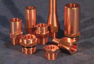
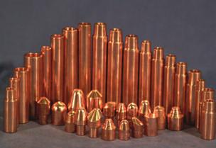
6 caps and shanks Tuffcap electrodes consist of two pieces: a shank and a replaceable cap. These two-part electrodes can offer major economies, because when the nose geometry is worn out, only the cap needs to be replaced. And it costs far less than a standard one-piece electrode. (A Tuffcap shank will normally outlast twenty caps.) Also, electrode inventory can be kept small because all nose designs will fit the same size shank. TWO TYPES: offers two kinds of Tuffcap electrodes. One uses a male cap that fits into the shank. The other has a female cap that fits over the shank. FEMALE AND MALE CAPS are available in the widest range of sizes, alloys, and styles. They are made in both Class 1 and Class 2 alloy, and in sizes to fit- shanks sized 4 through 7 RW. Male caps are more effectively cooled than female caps. ALL CAPS are made with the same nose designs in conformance with RWMA standards. SHANKS are made of Class 2 alloy, either straight, or bent to provide an offset. Shanks other than those cataloged can be special ordered. Tuffcap, caps and shanks should be used only in a directly opposed, straight-line manner. They do not work as well as standard electrodes on heavily coated metal such as galvanized or tin-plate. TUFFTRODE-Z CAPS FOR COATED STEELS To avoid electrode sticking problems common when welding galvanized and aluminized materials, these copper chrome-zirconium alloy caps are offered. They give the same performance as dispersion-strengthened caps but cost far less. They are Class 2 caps in mechanical and physical properties. Both male and female caps are offered in all the standard nose designs. Female Cap Type Electrode Assembly Male Cap Type Electrode Assembly Size 5 RW straight and offset style shanks holding male type caps with swivel heads. These caps are cataloged on pages 6 & 7. NEW! SUPER NOSE DESIGN CAPS To avoid mushrooming and brassing problems associated with standard designs, these caps have a self-dressing weld face ring that acts as a control zone. The Super Nose caps are available in s new Z material, that eliminates electrode sticking problems common when welding galvanized and aluminized materials. Both male and female designs are offered, designed to fit shanks with 5 RW taper. U.S. Patent Number 5,155,320 Other patents pending 5
7 caps and shanks STRAIGHT SHANKS FOR MALE CAPS (CLASS 2*) MALE CAPS SHANKS 4 RW TAPER Shank Assembled Descip- Part Length Length tion No. 1-1/4 2 TG /2 2-1/4 TG /4 2-1/2 TG /4 TG /4 3 TG /2 3-1/4 TG /4 3-1/2 TG /4 TG /4 4 TG POINTED TIPS A Alloy Taper of Descrip- Part Class Adapter tion No. Shank 1 4RW TA RW TA RW TA RW TA &2 5RW TA-25Z RW TA RW TA SHANKS 5 RW TAPER SHANKS 6 RW TAPER 1-1/4 2 TG /2 2-1/4 TG /4 2-1/2 TG /4 TG /4 3 TG /2 3-1/4 TG /4 3-1/2 TG /4 TG /4 4 TG /2 2-1/2 TG TG /2 3-1/2 TG TG DOME TIPS B 1 6RW TA RW TA RW TA RW TA Z 4RW TS-24Z Other sizes available Z 5RW TS-25Z RW TB RW TB SHANKS 7 RW TAPER 1-1/2 2-1/2 TG TG /2 3-1/2 TG TG RW TB RW TB RW TB RW TB E NOSE 4 AND 5 CAP F NOSE 4 AND 5 CAP BENT SHANKS FOR MALE CAPS (CLASS 2*) SHANKS 4 RW TAPER Shank Off- Length Descip- Part Length set tion No. 2-1/2 1/2 3-1/4 TG /2 3/4 3-1/4 TG / /4 TG /2 3-3/4 TG /4 3-3/4 TG /4 1 4 TG /4 1-1/4 4 TG FLAT TIPS C 1 7RW TB RW TB RW TC RW TC RW TC RW TC RW TC RW TC RW TC RW TC RW TC RW TC SHANKS 5 RW TAPER 2-1/4 1/4 3 TG /2 1/2 3-1/4 TG /2 3/4 3-1/4 TG / /4 TG /2 3-3/4 TG /4 3-3/4 TG /4 1 4 TG /4 1-1/4 4 TG OFFSET TIPS D 1 4RW TD RW TD RW TD RW TD RW TD RW TD RW TD RW TD RW TD RW TD * Class 3 Available 6
8 caps and shanks STRAIGHT SHANKS FOR FEMALE CAPS (CLASS 2*) FEMALE CAPS SHANKS 4 RW TAPER Shank Assembled Descrip- Part Length Length tion No. 1-1/2 2 TP /4 2-1/4 TP /2 TP /4 2-3/4 TP /2 3 TP /4 3-1/4 TP /2 TP /4 3-3/4 TP /2 4 TP POINTED TIPS A.840 Alloy Taper of Descrip- Part Class Adapter tion No. Shank 2 4RW TP-24A RW TP-25A SHANKS 5 RW TAPER 1-1/2 2 TP /4 2-1/4 TP /2 TP /4 2-3/4 TP /2 3 TP /4 3-1/4 TP /2 TP /4 3-3/4 TP /2 4 TP DOME TIPS B 2 6RW TP-26A Z 4RW TP-24SZ Other sizes available Z 5RW TP-25SZ SHANKS 6 RW TAPER 1-1/2 2 TP /2 TP /2 3 TP /2 TP RW TP-24B RW TP-25B E NOSE 4 AND 5 CAP F NOSE 4 AND 5 CAP 2 6RW TP-26B For improved cooling, female shanks are drilled through (to put water in contact with cap). Shanks may be ordered with a blind water hole, upon request. FLAT TIPS C 9/32 2 4RW TP-24C BENT SHANKS FOR FEMALE CAPS (CLASS 2*).840 SHANKS 4 RW TAPER Shank Off- Length Descrip- Item Length set tion No. 2-3/4 1/2 3-1/4 TP /4 3/4 3-1/4 TP / /4 TP /4 1/2 3-3/4 TP /4 1-1/4 3-3/4 TP /2 1 4 TP RW TP-25C RW TP-26C OFFSET TIPS D 2 4RW TP-24D SHANKS 5 RW TAPER 2-3/4 1/2 3-1/4 TP /4 3/4 3-1/4 TP / /4 TP /4 1/2 3-3/4 TP /2 1 4 TP /4 1-1/4 3-3/4 TP RW TP-25D RW TP-26D * Class 3 Available 7
9 bent tips DOUBLE-BEND, WITH STANDARD NOSE DESIGNS These standard cold-formed tips are bent from straight tips (some after added machining) and have the same hardness and conductivity. They outlast, many times over, the old cast and forged tips of similar geometry, which are impossible to cool adequately. The table shows a wide range of tips generally available from stock. For sizes not shown, refer to the diagrams and description key at the bottom of the page, and order what you need. All measurements will be accurate. However, over-all length, in 1/8-in. multiples, will be held to within 1/16-in. Tapers, water holes, and nose designs are the same as the standard straight tips in this catalog. Water tubes can be furnished. Standard nose designs other than those shown here may be furnished on short order. Follow the Key to Description, using a B for Dome nose, C for flat nose, E for truncated cone, and F for radius nose. DOUBLE-BENT, ADDITIONAL NOSE DESIGNS A POINTED NOSE B DOME NOSE C FLAT NOSE D OFFSET NOSE KEY TO DESCRIPTION F = Cold-Formed, Double-Bend Tips X = Nose Type A B C D FX-YZLD-O Y = RWMA Alloy Class 1 = Class 1 2 = Class 2 Z = RW Taper Number 4 =4RW 5 = 5RW L = Length in inches Refer to table for availability D = Additional Length in 16ths O = Offset in 16ths Refer to table for availability T = With water tubes Example: FB T Taper No. 4 RW 5 RW CLASS I CLASS 2 FA Pointed Nose FD Offset Nose FA Pointed Nose FD Offset Nose Length Offset Descrip- Item Descrip- Item Descrip- Item Descrip- Item tion No. tion No. tion No. tion No. 1-1/2 7/16 FA /16 1 FD /4 1/2 FA FA /4 3/4 FA /8 3/8 FA FA /8 3/4 FA /8 1-1/4 FA FD FA FD /2 1/2 FA /2 1 FA FD FA FD /8 3/4 FA FA FD /4 1/2 FA FA FD /4 1 FA /4 1-1/4 FA /8 3/4 FA /8 1-1/4 FA FA FA FA /8 1-1/4 FA /2 1 FA /4 1/2 FD /4 1-1/4 FD FD /8 3/8 FA FA FD /8 3/4 FD FA FD /16 1-5/16 2-1/2 1/2 FA FA /2 1 FA /4 1/2 FA FD FA FD /4 3/4 FA /4 1 FA FD FA FD /8 1 FA /8 1-1/4 FA FA /2 FA FA FD /4 FA FA FD /4 1 FA FA /8 3/8 FD /8 1-1/4 FA FD FA FD /2 1/2 FA FA /2 1 FA FD
10 bent tips A POINTED NOSE FA FA FA FA FA FA FA FA FA FA FA FA FA FA FA FA FA FA FA FA FA FA FA FA FA FA FA FA FA D OFFSET NOSE FD FD FD FD FD FD FD FD FD FD FD FD FD FD FD FD FD FD
11 bent tips SINGLE-BEND TIPS FP Part No FP Part No FP Part No FP Part No FP Part No FP Part No FP Part No Cold-formed tips with a single bend have standard pointed-nose design. Other single-bend tips with flat noses (below) or other special designed noses and configurations are available on special order. These are of Class 2 alloy; Class I alloy can also be ordered. SE-4268 Part No MISCELLANEOUS TIPS SE-4269 Part No Double bend and flattened tips are made from bar stock. These are some of the standard designs available, but special designs can also be made. These are of Class 2 alloy; Class I alloy can also be ordered. SE-4270 Part No SE-4271 Part No SE-4272 Part No SE-4273 Part No SE-4274 Part No SE-4275 Part No SE Part No SE-4276 Part No
12 miscellaneous tips These standard bent tips are in addition to those shown on page 9. They are of class 2 alloy; Other alloys can also be ordered. SE-4284 (short water hole) Part No SE-4285 Part No SE-4286 Part No SE-4287 Part No SE-4288 Part No SE-4282 Part No SE-4283 Part No SE-4277 Part No SE-4278 Part No SE-4279 Part No SE-4280 Part No SE-4281 Part No
13 threaded tips Tuffaloy threaded electrodes are Class 2 alloy. Other materials are available. FLAT ELECTRODES A B C Overall Tip Male Description Part No. Length Dia. (Hex) Thread 2 1 5/ C / C / C /4 3/ C TRUNCATED ELECTRODES A B C Overall Tip Male Description Part No. Length Dia. (Hex) Thread 2 1 5/ E / E / E /4 3/ E C NOSE ELECTRODES A B C Overall Tip Male Description Part No. Length Dia. (Hex) Thread 3/4 5/8 7/ C /4 5/8 3/ C E NOSE ELECTRODES A B C Overall Tip Male Description Part No. Length Dia. (Hex) Thread 3/4 5/8 7/ E

14 swivel tips Swivel tips have ball-jointed swivel heads to compensate for minor misalignment, and to eliminate marking of the work surface. They are all machined from Class 2 alloy bar stock. The S-and SS- Series tip water hole does not reach the head. In the OS and OSH models, the water does contact the head, and O-rings are used to seal it. In the SS Series a spring is used to keep pressure on head for better positioning. Class 1 and class 3 heads are also available. Note: Standard swivel tilt is approximately 18, a 25 swivel is available on request. Add suffix HS to above part number. S-Series* (Tuffcap Design) Taper No. Face S-Series OS-Series OSH-Series SS-Series Dia. Descrip- Part Descrip. Part Descrip- Part Descrip- Part F tion No. tion No. tion No. tion No. 7/8 S CT* 1 S /4 S S-Series OS-Series OSH-Series SS-Series 7/8 S OS RW 1 S OS /4 S OS /8 S OS S OS OSH SS RW 1-1/4 S OS OSH SS /2 OSH OSH RW 2-1/ *Will fit Tuffcap adapter shanks having No. 5 RW tapers, as shown on page 6. F 2 refractory metal-faced tips Nose Taper Facing Alloy Dimensions Descrip- Part Type No. Class A B tion No. 4RW 14 3/16 3/8 A M RW 13 3/16 3/8 A W Pointed 5RW 11 1/4 3/8 A W RW 14 1/4 3/8 A M RW 13 1/4 3/8 A W RW 11 1/2 1/4 B W Dome 5RW 11 5/8 1/4 B W RW 13 5/8 1/4 B W RW 11 1/2 1/4 C W RW 14 1/2 1/4 C M Flat 4RW 13 1/2 1/4 C W RW 11 5/8 1/4 C W RW 14 5/8 1/4 C M RW 13 5/8 1/4 C W The copper-tungsten, tungsten and molybdenum-faced tips listed here withstand greater heat and pressure, at the expense of some conductivity. Besides being used for spot welding high resistance base metals, they are useful in achieving heat balance when welding dissimilar metals. (The higher resistance electrode is used against the lower resistance, or thinner, member, to help contain the heat generated.) They have the same diameters and tapers as the standard straight tips in this catalog. Bodies are of Class 2 alloy. Lengths other than those shown can be ordered. POINTED NOSE A DOME NOSE B FLAT NOSE C 14

15 cylinder-mounted holders These standard-tip holders are mounted directly to air or hydraulic cylinder pistons. They are ideal for assembling special multi-head resistance welding equipment. Current and coolant water are brought to each of the holders separately. Electrode adapters for the tip diameter being used and in lengths to suit your set-up are ordered separately: see page 16. Water tubes, for carrying water into the tip, should also be ordered separately. offers both straight and offset holders for cylinder mounting. Clamps, hose connections, water tubes and adaptors are not included. Order separately. OFFSET HOLDERS Offset holders are offered in eight offset sizes, from 1/8 to 1 inch. The standard models have a 1/2-NPT adapter socket, to hold adapters for 4 & 5RW tips. Ordering a 3/4-NPT socket will permit adapters for 6 & 7RW tips to be used. ORDER CLAMP SEPARATELY OFFSET HOLDERS 4 & 5 RW 6 & 7RW Offset Width Part No. Part No. (inches) (inches) 1/2 Pipe 3/4 Pipe For 7/8 straight-thread adapters use suffix 7/8-14 N.F. Example: /8-14 NF. STATIONARY WATER TUBES FOR 4 & 5 RW TIPS FOR 6 OR 7 RW TIPS HOLDER CLAMP 101-2: PART NO /4 NTP HOSE CONNECTION 8241: PART NO To determine distance adapter sticks out from holder, deduct 1/2-in from length of adapter selected. Water tubes 1/2-in. longer than adapter will install approximately flush with adapter face. STATIONARY WATER TUBES FOR 4RW USE FOR 5RW, 6RW OR 7RW USE Length Description Part No. Description Part No. 3/ / / / / / /
16 tip adapters threaded electrode adapters are used to provide longer electrode holder life, by providing a changable tip socket in holders having threaded openings. Class 2 alloy. Other alloys available. A B C D E Pipe Thread Taper Body Body Over-All Description Part Number or Taper Socket Size Length Length 1/4 7/8 AD /8 1 AD /8 1-1/4 AD /8 1-1/2 AD /8 1-3/4 AD /8 2 AD /2-14 4RW 1 Hex 1-5/8 2-1/4 AD * NPT 1-7/8 2-1/2 AD /8 2-3/4 AD * 2-3/8 3 AD /8 3-1/4 AD * 2-7/8 3-1/2 AD /8 3-3/4 AD * 3-3/8 4 AD /8 5 AD * 1/4 7/8 AD /8 1 AD /8 1-1/4 AD /8 1-1/2 AD /8 AD * 1-1/8 1-3/4 AD /8 2 AD /2-14 5RW 1 Hex 1-5/8 2-1/4 AD * NPT 1-7/8 2-1 /2 AD /8 2-3/4 AD * 2-3/8 3 AD /8 3-1/4 AD * 2-7/8 3-1/2 AD /8 3-3/4 AD * 3-3/8 4 AD /8 4-1/2 AD /4 7/8 AD /8-14 4RW 1 Hex 3/8 1 AD NPT 7/8 1-1/2 AD * 1-3/8 2 AD * 1/4 7/8 AD /8 1 AD * /8 1-1/4 AD /8-14 5RW 1 Hex 7/8 1-1/2 AD NPT 1-1/8 1-3/4 AD /8 2 AD * 1-7/8 2-1/2 AD * 2-3/8 3 AD * 3-3/8 4 AD * 3/16 1-1/8 AD * 7/16 1-3/8 AD * 9/16 1-1/2 AD /16 1-3/4 AD /4-14 5RW 1.25 Hex 1-1/16 2 AD NPT 1-9/16 2-1/2 AD /16 3 AD /16 3-1/2 AD /16 4 AD /16 5 AD /16 1-1/4 AD * 7/16 1-3/8 AD /16 1-1/2 AD /16 2 AD /4-14 6RW 1.25 Hex 1-9/16 2-1/2 AD NPT 1-13/16 2-3/4 AD * 2-1/16 3 AD /16 3-1/2 AD /16 4 AD /16 4-1/2 AD /16 5 AD /16 1-1/2 AD /16 2 AD /16 2-1/2 AD /4-14 7RW 1.25 Hex 2-1/16 3 AD NPT 2-9/16 3-1/2 AD /16 4 AD /16 4-1/2 AD /16 5 AD AD RW 5RW 1 Hex 2 3 AD AD /4 1-1/8 AD AD RW 4RW 7/8 Hex 1-1/2 2-1/2 AD * 2 3 AD AD AD /2 2-1/2 AD RW 5RW 7/8 Hex 2 3 AD-55-3* 3 4 AD AD RW 6RW 1 Hex 1-1/8 2 AD RW 4RW 1 Hex 1/4 1-1/4 AD RW 5RW 1 Hex 1/4 1-1/4 AD RW 4RW 1 Hex 1/4 1-1/2 AD /4 1 AD RW 5RW 1 Hex 3/4 2 AD /4 3-1/2 AD * 2-3/4 4 AD-75-4* * Not commonly stocked - other adapters available upon request AD , AD , AD , AD , AD-45-2, AD-45-4, AD-55-30, for 5 RW Tip, Part No { /8 D. Barrel Required for 1-12 NF Adapter { { { AD , AD , AD , AD , AD , AD , AD-54-1, AD-75-2, AD-55-90, for 5 RW Tip, Part No AD-54-90, for 4 RW Tip, Part No STRAIGHT THREADED ADAPTERS FOR MULTI-SPOT BARREL AND CLAMP { 1.25 Hex 1.25 Hex 1.25 Hex 1.25 Hex A B Description Part No. 4 RW TAPER - 7/8-14 NF 3/8 1-1/8 AD /2 1-1/4 AD /8 1-3/8 AD /4 1-1/2 AD /4 AD /4 2 AD /2 2-1/4 AD /4 2-1/2 AD /4 3 AD /4 3-1/2 AD RW TAPER - 7/8-14 NF 3/8 1-1/8 AD /2 1-1/4 AD /8 1-3/8 AD /4 1-1/2 AD /4 AD /4 2 AD /2 2-1/4 AD /4 2-1/2 AD /4 3 AD /4 3-1/2 AD RW TAPER NF 3/8 1-1/8 AD /2 1-1/4 AD /8 1-3/8 AD /4 1-1/2 AD /4 AD /4 2 AD RW TAPER NF 1-1/2 2-1/4 AD /4 2-1/2 AD /4 AD /4 3 AD /4 3-1/2 AD

17 multi-spot barrel and clamp 101 SERIES HOLDERS (For 4 & 5 RW Tips) HOLDER CLAMP 101-2: PART NO /4 NPT HOSE CONNECTOR, 8241: PART NO STRAIGHT HOLDERS Straight holders for multi-spot welding are available in two sizes, to carry tips having four different diameters. Series 101 holders are for 4 & 5RW tips, and Series 102 holders are for 6 & 7RW tips. They may be ordered with one or two sets of coolant ports. Mating electrical contact surfaces of both the barrels and the clamp are silver plated. Item Numbers for replacement barrels and clamp parts are called out on the drawings. ADAPTER (1/2 NPT) HOLDER BARREL: SINGLE-PORTED, 101-A: PART NO DOUBLE-PORTED, 101-B: PART NO FOR WATER TUBES SEE PAGE 16 Threaded adapters for barrels can be found on page 16. To determine distance adapter sticks out from holder, deduct 1/2 from length of adapter selected. Water tubes 1/2 longer than adapter will install approximately flush with adapter face. 102 SERIES HOLDERS (For 6 & 7 RW Tips) ADAPTER (3/4 NPT) HOLDER BARREL: SINGLE-PORTED, 102-A: PART NO DOUBLE-PORTED, 102-B: PART NO HOLDER CLAMP 102-2: PART NO /4 NPT HOSE CONNECTOR, 8241: PART NO FOR WATER TUBES SEE PAGE 16 To determine distance adapter sticks out from holder deduct 3/4 from length of adapter selected. Water tubes 3/4 longer than adapter will install approximately flush with adapter face Barrel Only for 7/8-14 NF Adapter Barrel Only Dual 20 Offset for 7/8-14 NF Adapter CLAMP AND BARREL ARE SEPARATE PARTS Adapters, water connectors and water tubes (see page 15 & 16) are sold separately. HOLDERS and CLAMPS Holders Number of Coolant Ports For Tip One Set Two Sets Clamp Sizes Descrip- Part Descrip- Part Descrip- Part tion No. tion No. tion No. 4 & 5 RW 101-A B & 7 RW 102-A B & 5 RW 103-A B RW SH-102-B (1-3/8 diameter barrel) only for 1-12 NF adapter 17

18 straight welding tip holders GOLDCROWN AND STANDARD EJECTOR HOLDERS with self-adjusting water tubes straight tip-ejecting holders deliver dependable, first class performance. They are designed with maximum simplicity to require minimum maintenance. All straight holders now feature exclusive spring-loaded self-adjusting water tubes to ensure the proper flow of coolant through resistance welding electrodes. The larger ejector holders incorporate bigger fittings for higher coolant flow rates. Goldcrown premium holders are made of extra-strength Class 2 alloy and are ground and polished to yield greatest conductivity. ADAPTER SIZE FOR THREADED BARRELS Part Descrip- THD No. tion Taper Size RW 5/8-14 NPT RW 5/8-14 NPT AD RW 3/4-14 NPT THESE ADAPTERS ARE SUPPLIED with the holder GOLDCROWN STANDARD Tip Barrel Barrel Descrip- Part Descrip- Part Socket Dia. Length tion No. tion No. RW 5/8 4 8 E / E /4 4 8 E /4 5 8 E / E / E * 7/8 4 8 E /8 5 8 E / E / E E SHE E SHE E * SHE * E SHE E SHE E * SHE * 1-1/4 4 8 E SHE /4 5 8 E SHE /4 6 8 E * SHE * 1-1/4 7 8 E SHE / E SHE / E SHE / E * SHE * 1-1/ E SHE /2 4 8 E * SHE /2 5 8 E SHE /2 5 8 E A * SHE A * 1-1/2 6 8 E SHE /2 6 8 E A SHE A /2 7 8 E SHE / E SHE / E A * SHE A * 1-1/ E SHE / E A * SHE A * 1-1/ E * SHE * 1-1/ E SHE Suffix A in holder description denotes a threaded tip adapter is supplied *Item not normally stocked Cross-section of holders with barrels 1 inch or more in diameter. O-RING SEALS EJECTOR TUBE SELF-ADJUSTING WATER TUBE EJECTOR BUTTON BARREL LENGTH Cross-section of holders with barrels 7/8 inch or less in diameter. 18
19 tip holders GOLDSPOT AND STANDARD NON-EJECTOR HOLDERS with self-adjusting water tubes straight non-ejector holders are now equipped with the same springloaded self-adjusting water tubes as the Goldcrown ejector unit, so electrode cooling is facilitated and improved. They are low in initial cost and inexpensive to maintain. Simple design and few parts contribute to low maintenance cost and excellent performance. Holders are heavyduty and built to withstand very high welding rates. Goldspot premium holders have barrels of Class 2 alloy, ground and polished for best conductivity. Examples of standard holders in use are shown on page 22. ADAPTER SIZE FOR THREADED BARRELS Part Descrip- THD No. tion Taper Size RW 5/8-14 NPT RW 5/8-14 NPT AD RW 3/4-14 NPT THESE ADAPTERS ARE SUPPLIED with the holder GOLDSPOT STANDARD Tip Barrel Barrel Descrip- Part Descrip- Part Socket Dia. Length tion No. tion No. RW 5/8 4 8 N / N * 3/4 4 8 N /4 5 8 N * 3/ N * 3/ N * 7/8 4 8 N /8 5 8 N * 7/ N / N * N SHN N A SHN A N SHN N A * SHN A * N * SHN * N SHN N A SHN A N SHN N A SHN A N * SHN * 1-1/4 4 8 N * SHN * 1-1/4 4 8 N A SHN A /4 5 8 N SHN /4 5 8 N A SHN A /4 6 8 N * SHN * 1-1/4 7 8 N * SHN * 1-1/ N SHN / N A * SHN A * 1-1/ N SHN / N A SHN A / N * SHN * 1-1/ N * SHN * 1-1/2 4 8 N * SHN * 1-1/2 4 8 N A * SHN A * 1-1/2 5 8 N SHN /2 5 8 N A SHN A /2 6 8 N * SHN * 1-1/2 7 8 N SHN / N * SHN * 1-1/ N SHN / N A * SHN A * 1-1/ N * SHN * 1-1/ N * SHN * Suffix A in holder description denotes a threaded tip adapter is supplied *Item not normally stocked Cross-section view of holders with barrels 1 inch or more in diameter. 19

20 nickel plated ejector holders Barrel Tip Barrel Descrip- Holder Diameter Socket RW Length tion Assy NHE /4 4 8 NHE NEH /4 5 8 NEH NEH / NEH NEH / NEH NICKEL PLATED EJECTOR HOLDERS with self-adjusting water tubes nickel plated ejector holders feature extra strength Class 2 Tuff 77 alloy and are ground, polished and nickel plated for superior conductivity. These holders also feature exclusive spring-loaded self-adjusting water tubes to ensure proper water flow any electrode. Descrip- Holder 1 Head 2 3 Tube 4 Water 5 Hose 6 Barrel 7 Head 8 All tion Assy. Assy. Barrel Assy. Tube Conn. O-Ring O-Ring Thread NHE B NHE B NEH B NEH B NEH B NEH B NEH B NEH B


21 tip holders CLOSED-COUPLED HOLDERS For use where welding space is limited. Standard body length is 3 inches. Other lengths are made on request; minimum length 2 inches. 60 Body Tip Descrip- Part Dia. Socket tion No. 3/4 4RW N /8 4RW N /8 5RW N RW N RW N /4 4RW N /4 5RW N /2 4RW N * 1-1/2 5RW N * *Item not normally stocked BARREL LENGTH 3 5/16 O.D. TUBE RW TAPER SOCKET 1/4 O.D. ADJUSTABLE WATER TUBE SHANK LENGTH 4-1/8 ADJUSTABLE WATER TUBE USE It is very important that resistance welding electrodes be kept as cool as possible; excessive heat softens them, allowing the nose to mushroom and weld quality to drop. Adjustable water tubes are used to deflect incoming coolant water to the full extent of the water hole in the electrode. Before installing a tip, check that there is an adjustable water tube in place and that it is pulled out far enough so that it will contact the end of the water hole in the tip. The drawing shows a typical straight holder, but the principle is the same for all types of holders. Adjustable water tube correctly positioned in tip. Cold water will strike the hottest part of the tip first. 21

 holders may be used in place of the non-ejector holders listed. The Tee Connector is Class 3 RWMA alloy. AD-584-90, for 4RW Tip Part No.")

22 offset holders 2-1/4 BARREL LENGTH HOLE DIA. (TEE CONNECTOR) 90 BARREL DIA. 30 AD E, for 5RW Tip Part No AD , for 4RW Tip Part No AD , for 5RW Tip Part No SHANK DIA. SHANK LENGTH 4 UNIVERSAL HOLDER ASSEMBLIES Holders, Tee Connectors, and Adapters may be assembled as shown, line by line in the table, to make up holder assemblies that will do spot welding in many otherwise inaccessible places. Goldcrown (ejector-type) holders may be used in place of the non-ejector holders listed. The Tee Connector is Class 3 RWMA alloy. AD , for 4RW Tip Part No AD , for 5RW Tip Part No HOLDERS TEE CONNECTORS Barrel Barrel Descrip- Part Hole Shank Descrip- Part Dia. Length tion. No. Dia. Dia. tion No. 1 8 N A T /4 8 N A /4 1 T /4 8 N A /4 1 T /4 8 N A /4 1-1/4 T /4 8 N A /4 1-1/4 T /4 8 N A /4 1-1/4 T /2 8 N A /2 1-1/2 T /2 8 N A /2 1-1/2 T /2 8 N A /2 1-1/2 T ADAPTERS TO CHOOSE FROM Tip Angle Descrip- Part Socket Degrees tion No. 4RW 90 AD RW 30 AD RW 90 AD RW 30 AD RW 90 AD welder arms Class 2 spot welding machine arms made by Tuffaloy reduce set up time and give longer life. Electrode holder shanks can be attached to these arms from the front, by bolting the cap over them. This means no extra clearance is required between the arms to allow running a shank up (or down) into a hole in the arm. It makes the insertion of Tuffaloy multiplewelding holders much easier. One of the most common failures of welder arms is the destruction of the bolt hole threads, due to the relatively soft copper involved. Tuffaloy arms have a transverse steel bar insert in which the bolt hole threads are cut. This provides greatly increased thread life. Standard arm configurations are shown in the table. Special arms are also available. A B C Arm Hole Arm Diameter Diameter* Length Description 12 SH SH SH SH /2 1-1/4 16 SH SH SH /2 16 SH SH *These diameters will be supplied unless otherwise specified. Part No. 22


23 standard offset holders STANDARD OFFSET HOLDERS Cast Class 3 Alloy offset holders combine long life with good conductivity. Threaded tip adapters are easily replaced when tip socket is worn beyond use, or when you wish to change to a different taper size. OFFSET 2 OR 4 2 (MAX.) offset holders are made in 2- and 4-inch offsets, and in four shank sizes, with 90 and 30* heads. They are supplied with adapters for No. 4 or No. 5 RW taper tips. Tip Ejector mechanisms are available on all 90* head holders and the 30 head 4-in. offset holders. When ordering this feature change order number prefix from ON to OE. Example: OE SHANK LENGTH 3-1/2 HEAD HEIGHT 2 1/4 ON EJECTOR-TYPE MODEL ADAPTERS SUPPLIED: 4RW: AD-584 5RW: AD Adapter Tip Socket Socket Angle TWO-INCH OFFSET HOLDERS 3/4 7/ /4 1-1/2 SHANK DIA. SHANK DIA. SHANK DIA. SHANK DIA. SHANK DIA. Descrip- Part Descrip- Part Descrip- Part Descrip- Part Descrip- Part tion No. tion No. tion No. tion No. tion No. 4RW 30 ON ON * ON ON ON * 4RW 90 ON * ON * ON ON ON * 5RW 30 ON * ON * ON ON ON * 5RW 90 ON * ON * ON ON ON RW 30 ON * ON * ON ON ON * 4RW 90 ON * ON * ON ON ON * 5RW 30 ON * ON * ON ON ON RW 90 ON * ON * ON ON ON *May not be in stock FOUR-INCH OFFSET HOLDERS USING STANDARD HOLDERS Figure 1: An offset holder over a low-profile paddle-type holder that works in confined spaces. Figure 2: An offset holder with bent tip is used to weld close to the corner of a box section. Figure 3: A universal holder (economical because it adjusts to many jobs) over a closecoupled holder. Figure 4: A platen set-up using platen-mounted standard tips under an Equa-Press dual holder. 23

24 variable-offset holders VARIABLE-OFFSET HOLDERS Shank Descrip- Part Dia. tion No. 1 SH /4 SH /2 SH /2 4 MIN. 5 MAX. 3-1/2 VARIABLE OFFSET HOLDER AND STRAIGHT SHANK TIPS These offset holders provide a range of offset dimensions rather than one fixed amount, as with other one-piece offset holders. The top has a long shank and can be moved in or out to vary the offset anywhere between four and five inches. The holders, all of Class 3 alloy, are made in three barrel diameters: 1, 1-1/4, and 1-1/2 inches. The tips are positional because they have no taper: they have straight shanks, and are held in any selected position by a locking-wedge device in the holder. Tips are made in one and two-piece designs. The one-piece tips are offered with the nose designs shown. The two-piece tips are made up by combining the shanks shown here with Tuffcap caps (normally used with No. 5 RW size Tuffcap shanks). Either male or female tips can be used, with any #5 nose design offered on pages 6 & 7. All integral tips and shanks shown here are of Class 2 alloy. STRAIGHT-SHANK TIPS Type Nose Length Descrip- Part of Tip A tion No. Pointed 1 SE Offset 1 SE Dome 1 SE Dome 1 SE Pointed 2 SE Offset 2 SE Dome 2 SE Dome 2 SE STRAIGHT-SHANK TUFFCAP SHANKS Tuffcap Nose Cap Length Angle Type A Description Part No. Male 3/4 90 SE Male 3/4 15 SE Female 1 90 SE Female 1 15 SE


25 paddle-type holders PADDLE-TYPE HOLDERS AND SOCKET-TYPE TIPS This holder is for welding in very restricted areas. It provides a very low head height and a four-inch offset. It is made in shank diameters of 3/4, 7/8, 1, and 1-1/4 inches. An adapter bushing is used to add a 1-1/2-in. dia. model to the line. Each holder comes complete with a socket-type tip (SE-3101) and holding screw. The tip may be inserted in either side of the paddle. Holders are of Class 2 alloy. Tips are available in Class 1, Class 2, Class 3 alloy, or Z alloy. The four socket-type tips shown here can be used in special welding fixtures and dies as well as in the paddle-type holders. 11/16 OFFSET 4 Shank Descrip- Part Dia. tion No. 3/4 P /8 P P /4 P /2 P SHANK LENGTH 3 FLAT FACED Class 1 SE Part No Class 2 SE-3099 Part No Class 3 SE-3111 Part No ZIRC SE-3099-Z Part No Z TRUNCATED CONE Class 1 SE Part No Class 2 SE-3101 Part No Class 3 SE-3113 Part No ZIRC SE-3101-Z Part No Z OFFSET Class 1 SE Part No Class 2 SE-3102 Part No Class 3 SE-3123 Part No ZIRC SE-3102-Z Part No Z RADIUS FACED Class 1 SE Part No Class 2 SE-3110 Part No Class 3 SE-3133 Part No ZIRC SE-3110-Z Part No Z OFFSET 4 SHANK LENGTH 4 Shank Descrip- Part Dia. tion No. 1 SH /4 SH /2 SH /4 HEAVY-DUTY PADDLE-TYPE HOLDERS AND TIPS heavy-duty paddle-type holders are made of the stronger Class 3 alloy, for greater rigidity and minimum deflection, even under loads of 1000 pounds and more. Class 3 alloy provides 154% more tensile strength. Head height is a low 3/4-in. and the shank length is a usable 4 inches. Three low-profile electrodes of Class 2 alloy are offered for use in this heavy-duty holder. If applications permit greater head height, any standard No. 4 RW tip may be used. TRUNCATED CONE SE-3247 Part No OFFSET SE-3248 Part No FLAT FACED SE-3249 Part No


26 high pressure welding HIGH PRESSURE TIPS Spot and projection welding operations may utilize pressures over 2000 lbs. high-pressure tips have flat bottoms which eliminates tip jamming in tapered holders. Assembled tip and holder heights are always the same, as contrasted to tapered tips which can be forced into the sockets varying distances. high pressure tips can be used in the two holder styles shown: PM holders for mounting on the platens of press-type welders, and straight holders for spot welder arm mounting. The tips are held to the holders by a threaded coupling. Copper tungsten faced tips are available for high pressure wear and projection welding. FLAT FACED TRUNCATED CONE DOME NOSED Size 2 A Description Part No. 1/4 PME /16 PME /8 PME /16 PME /2 PME Size 1 PMC-2503 Part No Part No W Size 2 PMC-2104 Part No Part No W Size 1 PME-2503 Part No Size 1 PMB-2503 Part No STRAIGHT HOLDERS CLASS 2 ALLOY Straight holders are made for carrying high pressure tips in rocker arm welders or press-type welder horn extensions. They are made in two basic sizes, to accommodate the Size 1 and 2 tips. They are of Class 2 alloy and hold the tips in the same manner as do the PM holders. 1-3/4 5-5/16 3-1/2 Size Barrel Descrip- Part Dia. tion No / / / /
 4520 holder, Part No. 350-4520 PM HOLDERS PM holders are mounted directly to presstype welder platens, or are used as components of special weld fixturing.")

27 high pressure welding 1 BODY IS 2 WIDE BODY IS 1-1/2 WIDE 2-3/8 3/4 1-5/8 7 Size 1 PM holder (9/16-in. mounting bolts) 4510 holder, Part No Size 2 PM holder (3/4-in. mounting bolts) 4520 holder, Part No PM HOLDERS PM holders are mounted directly to presstype welder platens, or are used as components of special weld fixturing. Platen Mounting: PM holders bolt easily to the platen T-slots at any desired location, in a minimum of time (no intermediary device is required). Big halfinch mounting bolts may be used to assure good conductivity. They are the first such standard, stocked holders to be made available. They come in two sizes, to match standard T-slot spacing, and to hold the 2 sizes of tips shown. The small size 1 PM holder is for use on RWMA Size 1 press-type welders (3-1/2 in. spacing) and the large size, 2 PM holder is for Size 2 and 3 welders (5- and 6-in. spacing). The electrodes used do not require any particular radial positioning to obtain proper coolant flow. These are compact holders that may be used one-to-one or in multiples in close proximity to one another. Fixture Building: PM holders make special fixture building easy too. They can be bolted to a fixture or backup base as easily as to a platen. They are compact and have self-contained coolant systems that eliminate making a coolant manifold out of the fixture. Hose Connections: You may specify where you want the hose connectors in the hexagonal base. Select any two of the six possible locations and specify by using the symbols shown on the diagram (connector locations: A-B, or A-D, etc.). Position A-C is standard. (A-F and C-D are not possible.) 27
.")

28 platen-mounted holders PM HOLDERS PM holders may be mounted directly to presstype welder platens, or they can be used as components of special weld fixturing. They come in two sizes, which match standard T-slot spacings (either of which can be furnished to hold any of the four standard tips: 4, 5, 6 or 7 RW). The smaller holder is for use on RWMA Size 1 welders, which have the 3-1/2 spacing. The larger one is for the Size 2 and 3 welders, which have the 5- and 6-inch spacing. Big, half-inch mounting bolts may be used to assure good conductivity. The holders may be used one-toone or in multiples closely bunched. PM holders make special fixture building easy. They can be bolted to a fixture or back-up base as easily as to a platen. They are compact and have self-contained coolant systems. RW Tip Socket STANDARD TIP PM HOLDERS Size 1 (Small) Size 2 (Large) Descrip- Part Descrip- Part tion No. tion No * *Item not normally stocked FOR THREADED ELECTRODES Thread Size Size 1 Size 2 5/ / FOR THREADED ADAPTERS Thread Size Size 1 Size 2 7/ See adapters page 16 7/8-14 & 1-12 ONL Y This Style Only PM Holders Holder For 1 Dia. Electrodes For 1-1/2 Dia. Electrodes T-Slot Spacing Size Description Part No. Description Part No. 3-1/2 1PM & 6 2PM Size 2 PM Holder (3/4-in. mounting bolts) 1-3/4" 1/2" 4-1/4" THREAD SIZE (PIPE THREAD ON REQUEST) 1-1/2" HEX. 7/8 BODY IS 1-1/2 WIDE BODY IS 2 WIDE 2-3/8 Size 1 PM Holder 1-5/8 7 Size 2 PM Holder 28


29 nut and stud welding This style holder found at top of page 29 ELECTRODES Stud Electrodes Tuffaloy stud electrode tips are for projection-welding screws, bolts or pins, whether they pass through the sheet or are to be attached directly to its face. Nut Electrodes Tuffaloy projection weld nut electrodes are designed for either self-piloted or nonpiloted nuts. The pilots of the non-piloted-nut electrodes are spring-loaded so they can t interfere with the contacting of nut and sheet under welding pressure. Welding a stud through a hole in sheet metal. Welding a stud directly to face of sheet metal. Self-piloted nut aligns itself with the hole in sheet. Non-piloted-nut is guided by specially designed electrode. This style holder found at bottom of page 27 The various types and sizes of stud-and-nut welding electrodes and holders are described below. For excessive wear applications any of these electrodes may be ordered with refractory metal facings, such as 10W. STUD ELECTRODES W W W W 1/4 2-1/ W 5/16 & 8mm W 3/ W 6mm W 7mm W 9mm W 10mm W 3/ W 7/ W 1/ W 9/16 2-3/4 1-1/ W 5/ W 11/ W 3/ W 10mm W 12mm W SELF-PILOTED-NUT ELECTRODES.164 3/ W.190 3/ W.216 1/ W 1/4 5/16 2-1/ W 5/16 & 8mm 5/ W 3/8 3/ W 6mm 1/ W 7mm 5/ W 9mm 3/ W 10mm 3/ W 3/8 3/ W 7/16 3/ W 1/2 7/ W 9/16 7/16 2-3/4 1-1/ W 5/8 1/ W 11/16 1/ W 3/4 5/ W 10mm 3/ W 12mm 7/ W NON-PILOTED-NUT ELECTRODES Description No. Refractory - Part With 10W Face A B C Item Number E F G Description No. Part With 10W Face For Nut Pin Electrode Electrode Refractory - Size Length Length Diameter Item Number J K L Description No. Part With 10W Face For Nut Pin Electrode Electrode Refractory - Size Diameter Length Diameter Item Number W W W 1/ / W 5/16 & 8mm W 3/ W 6mm W 7mm W 9mm W 10mm I0W 3/ W 7/ W 1/ /4 1-1/ W 9/ I0W 5/ W 10mm W 12mm W 29

30 nut and stud welding ELECTRODE HOLDERS U.S. Pat. No. 3,504,159 Canada Pat. No. 858,060 Several standard electrode holders are manufactured by Tuffaloy to accommodate all the Tuffaloy stud-and nut electrode tips. 1-3/4 Straight Holders A B Barrel Dia. Length Diameter For 1 Dia. For 1-1/2 Dia. Electrodes Electrodes Descrip- Part Descrip- Part tion No. tion No /4 5-5/ /4 1-3/4 5-5/ /2 1-3/4 5-5/ / / / / / Straight Holders - Tuffaloy straight nut-and-stud-electrode holders are of the same high quality as the standard straight holders made for spot welder arm mounting. Coolant is brought to the tip and circulated around it. Holders are available in three barrel diameters. 3-1/2 5-5/8 Straight Holder ARCTIC HOLDERS ARCTIC STUD ELECTRODES A B C For Stud Electrode Electrode Diameter Length Diameter Part Number Shank Size X X / X X 1/ X 5/16 & 8mm X 3/ X 7/ X 6mm X 7mm X 9mm X 10mm X 1/ X 9/ / X 5/ X 11/ X 12mm X Arctic Electrodes - The Arctic system is a compact stud-andnut electrode with internal water cooling. Also available with optional air expulsion and platen mounts. Patent Pending ARCTIC NON-PILOTED-NUT ELECTRODES H J K L For Nut Pilot Electrode Electrode Diameter Diameter Length Diameter Description Description Part Number Shank Size X X X 1/ / X 5/16 & 8mm X 3/ X 6mm X 7mm X 9mm X 10mm X 7/ X 1/ / X 9/ X 12mm X 30
31 automatic nut feeder system components METRIC NUT ELECTRODES now stocks the head/pin style welding system components that adds to your selection for stud and nut welding needs. From our standard style to our Arctic, that produces higher quality welds and longer life, you can select the product that best meets your needs. Heads are made from RWMA class 2 material that are an optimal cost consumable. Class 3 and 10W are available for longer life. With a concave seat the pin locates in the center of assembly when air is applied to the system. This gives you a repeatable location for automated nut feeders to introduce the nut to the environment. Pins have a nonconductive surface on a steel matrix that gives longer life in a repetitive motion environment. With the threaded head securing the pin in place it makes it easy to replace the pin to meet your requirements. can design pins for special applications. HEADS Part Hole A B C Copper-Tungsten Number Dia. Pin Size Thread Dia. Faced Heads mm W mm W mm W mm M W mm W mm W mm W mm M W mm W mm W mm M W PINS Part A B C Number Nut OAL Base Pilot Dia mm mm mm mm mm mm mm mm mm mm mm mm mm mm BODIES Description Part A B C D Number OAL Dia. Thread Taper TDH-25A mm #4 TDH-25C mm #5 TDH-30A mm #5 TDH-35A mm #5 UPPER ELECTRODE Description Part A B C D Number ID OAL Dia. Taper TNFD 16-M mm.625 TNFD 20-M mm.75 TNFD 20-M mm RW TNFD 20-M mm.75 TNFD 20-M mm.75 A Pilot 31

32 automatic nut feeder system components GH SERIES NUT WELDING HEADS LENGTH COPPER TUNGSTEN O.D. HEX SIZE INSERT I.D. Length Tungsten OD Hex Size 175-GH-2 Series 175-GH-3 Series 175-GH-4 Series Insert I.D GH GH GH GH GH GH GH GH GH GH GH GH (6mm) GH GH GH GH GH GH GH GH GH GH GH GH GH GH GH GH GH GH GH GH GH GH GH (8mm) GH GH GH GH GH GH GH GH GH GH GH GH GH GH GH GH GH GH GH-2 Series 175-GH-3 Series 175-GH-4 Series Insert I.D GH GH GH GH GH (10mm) GH GH GH GH GH GH GH GH GH GH GH GH GH GH GH GH (12mm) GH GH GH GH GH GH GH GH GH GH GH GH GH GH GH GH GH GH GH
33 5 rw stud electrodes These series of Stud electrodes are made from RWMA Class 2 material with S 10W (copper tungsten) on the weld face and wrench flats for easy removal from holders. The Insulator is made to withstand the constant friction that is applied as the stud is inserted and removed. INSULATOR Screw ID. Length Part Thread Size A B Number W 6mm W W 0.312, 8mm W W 10mm W W 6mm W W 0.312, 8mm W W 10mm W W 12mm W W W W W W W 12mm W W W W W W BACKUP ELECTRODES FOR UPPERS W W W W 33

34 multiple welding QUICKEST WAY TO CUT WELDING COSTS Increased productivity without capital investment or increased labor costs just has to spell PROFIT. Hundreds of resistance welding users are profiting from the methods of multiple welding, to produce almost any assembly requiring closely spaced welds. The key is to think multiple! Whenever the welding machine goes through a cycle, have it do more than one weld at a time. It s easy and practical with one of the multiple welding devices: The Teeter-Tip dual tip adapter, the Equatip dual tip holder, the Equa-Press dual tip holder, or the Tri-Spacer. They re ready to go to work, cutting costs and increasing production efficiency for you. Study the multiple welding holders and adapters in this section. Learn their capabilities, think multiple, and you ll probably see many ways in which multiple welding can improve your operation. Remember that is prepared to provide any special fixturing you need. Show our engineers what you require, and they ll design a set-up to do it. TEETER-TIP DUAL TIP ADAPTERS U.S. Pat. 3,356,821 You can spot or projection weld in half the time by doubling the number of welds per machine stroke. Use Teeter-Tip dual tip adapters, which come with watercoolant fittings to beat high heat build-up. These, adapters transmit total pressures of 1000 lbs., and deliver equal current and pressure to each tip. They compensate for normal electrode wear, imperfect tip dressing, and work variations up to.060. LIGHT-DUTY adapters have no. 4 or 5 RW shanks, tip spacing to 4 inches, tip sockets for 1/2 or 5/8 diameter male Tuffcap caps, or 4 RW tips (5/8 cap sockets are standard). HEAVY-DUTY adapters have shanks from 5 to 7 RW size, tip spacing to 6 inches, tip sockets for 1/2 or 5/8 diameter male Tuffcap caps, or 4 or 5 RW tips (4 RW sockets are standard). These adapters have a deeper, stronger body. Two low-height 5/8 dia. cap-type tips are shown below. They are recommended for use in these adapters. Other standard caps, both 5/8 & 1/2 dia., are tabled on the next page. You must specify the size tip sockets you want, or the standard socket will be supplied. TRUNCATED CONE SE-6332 (Part No ) FLAT FACED SE-6296 (Part No ) Style Tip Shank Descrip- Spacing Socket Taper tion* Range Taper (inches) 4RW TT /4 to 2 4RW 5RW 4CT 5CT LIGHT 4RW TT to 4 4RW 5RW 4CT 5CT Duty 5RW TT /2 to 2 4RW 5RW 4CT 5CT 5RW TT to 4 4RW 5RW 4CT 5CT 5RW TT to 4 4RW 5RW 4CT 5CT 5RW TT to 6 4RW 5RW 4CT 5CT HEAVY 6RW TT to 4 4RW 5RW 4CT 5CT Duty 6RW TT to 6 4RW 5RW 4CT 5CT 7RW TT to 4 4RW 5RW 4CT 5CT 7RW TT to 6 4RW 5RW 4CT 5CT *When ordering, also state exact tip spacing and tip socket size, Example: TT /2-5CT. (5CT means 5/8 diameter cap, 4CT means 1/2 diameter cap.) LIGHT DUTY HEAVY DUTY 34
 is shown in box below.")

35 multiple welding Cylinder-mounting adapter shank, Part No ; clamp, Part No , not included 5 RW taper adapter shank, Part No EQUATIP DUAL TIP HOLDERS U.S. Pat. No. 3,558,847 The Equatip dual tip holder is a smaller version of the Equa-Press holder (on next page). It is more compact, and is more economical for those applications where it will work equally well. An even smaller device, the Equatip adapter (not water-cooled) is shown in box below. Using the Equatip holder, both tips contact the work squarely, because tip axes remain parallel to direction of force (unlike the Teeter-Tip adapters). An internal roller equalizes current and pressure between the two electrodes, and will compensate for work height variations up to 1/16. The holders are ordered with either 1 or 1-1/2 spacing between barrels, and with tip sockets to accept either male Tuffcap caps (5/8 dia.) or straight No. 4 RW electrodes. (Bent tips are not recommended.) The distance between welds can be varied by rotating offset-nose tips in the barrels. Equatip holders can be supplied with straight shanks for arm mounting, a tapered adapter shank for holder mounting, or a cylinder adapter shank to be clamped to a cylinder rod. Equatip holders can be used with forces up to 1000 lbs. EQUATIP HOLDERS For 5/8 Dia. For No. 4 Tuffcap Caps RW Tips BODY IS 1 THICK 4 5/8 DIA. TUFFCAP CAPS (5 CT) Nose Alloy Descrip- Part Style Class tion No. Pointed 1 TA TA Dome 1 TB TB Flat 1 TC TC Offset 1 TD TD Those caps are fully dimensioned on page 6. Tip Spacing & Descrip- Part Descrip- Part Mounting Style tion No. tion No. ONE-INCH SPACING: 1-in. shank /4-in. shank /2-in. shank RW adapter Cylinder adapter* /2-INCH SPACING: 1-in. shank /4-in. shank /2-in. shank RW adapter Cylinder adapter* *Without clamp 1/2 1 OR 1-1/2 1/2 2-7/8 7/16 For light-duty welding EQUATIP ADAPTER The Equatip dual tip adapter works like the Equatip holder, but it is not water-cooled and is meant for less demanding jobs. It costs less, and is a little smaller, barrels being 5/8 apart. Its straight tips are TUFFCAP caps, 1/2 in diameter. 1/2 DIA. TUFFCAP CAPS (4 CT) Nose Alloy Descrip- Part Style Class tion No. Pointed 1 TA TA Dome 1 TB TB Flat 1 TC TC Offset 1 TD TD Those caps are fully dimensioned on page , Part No RW 4046, Part No RW 35
.")

36 multiple welding EQUA-PRESS TM DUAL TIP HOLDERS U.S. Pat. No. 2,979,599 Canada Pat The Equa-Press Holder makes two identical welds at once. When it contacts the workpiece, the forging pressure is automatically equalized between the two electrodes, regardless of variations in work thickness, or electrode wear (up to 3/16 ). The two tip-holding barrels are sliding pistons, whose movements are controlled by a mechanical equalizing slide in the housing (see cutaway drawings). The spring s only function is to return the barrels to a fully extended position when there is no work contact. Maximum conductivity is maintained through sturdy copperalloy working parts. Spacing can vary up to 4 inches, using bent offset tips in Equa-Press holders having the standard barrel spacing of two inches (shown). Barrel spacing up to six inches is available as semistandard (see price list). These are drilled to order from stock components. To order you must give the barrel spacing desired, along with the Item number (from table). Equa-Press Holders are made in two mounting styles: platen models to mount directly to the platen on presstype welding machines, and shank models for rocker arm machines. All are available in two designs: the standard and the short (close-coupled) type. The short design is internally flood-cooled and takes up less space in the welder. Equa-Press holders can be used with forces up to 1500 lbs. Standard Design Short Design Mounting Style Descrip- Part Descrip- Part tion No. tion No. 1-in. shank /4-in. shank /2-1n. shank Platen Note: For best results, position the holder so that a line drawn through the electrode centers is at, or nearly at, right angles to the direction of the welder arms. Otherwise, the magnetic field between the arms can cause an excess of current to flow through the inboard electrode. 36


37 multiple welding LOWER ELECTRODE 1-1/2 SQ. 4 5 LOWER ELECTRODES Shank Diameter Description Part No / / LOWER HOLDERS AND ELECTRODES FOR USE WITH EQUA-PRESS HOLDER A lower, fixed, dual tip holder is offered for use with Equa-Press Holders. Like the Equa-Press, it has a standard two-inch tip spacing and helps make two welds at once, precisely alike. The standard trans-verse bar electrode shown is used when work geometry doesn t require tips on the lower side. They are water-cooled. A Case History: Projection welding brackets to automotive frame assemblies is twice as fast with an Equa-Press dual tip holder. Lower welding fixture acts as an inspection device, so warped parts are discovered before welding. Inspection time and scrap loss are both reduced. A Case History: Joining a piece of metal to itself is always tough. This job was done with an Equa-Press holder - two at a time. Lower clamp faces, carrying current, contact parts near the weld areas to avoid current bypassing weld projections. Two standard swivel tips make four welds, two per part. A 4 RW-Special 5RW-Special 5 RW BODY IS 1 THICK A Case History: Dual spot welding of panelled wall sections reduced welding costs enough to justify buying welding machine to do the job in-plant. Equa-Press holder with 5-inch spacing, and special (but simple) tooling to provide two offset tip adapters and matching holders were used. Electrodes are standard TUFFCAP caps. LOWER ELECTRODE STANDARD LOWER HOLDER - 2 SPACING 5 RW Lower Holder Shank Diameter Description Part No / / SPECIAL LOWER ELECTRODES Shank A Style Diameter Description* Tip Spacing (inches) Range (inches) 4 Body /4 to 2-7/8 1-1/ /4 to 2-7/8 1-1/ /4 to 2-7/8 8 Body to 6 1-1/ to 6 1-1/ to 6 * When ordering specify center distance and either 4RW or 5RW sockets In this drawing, two studs are projection welded in each welder stroke, using an Equa-Press dual holder over a pair of studwelding electrodes held in PMstyle holders. Here, four spot welds are made simultaneously on a corrugated part. An Equa- Press dual holder is used to hold two Teeter-Tip dual tip adapters. 37

 are equidistant from one another, all falling on a 1-5/8-in.")
38 multiple welding TRISPACER HOLDER Mounting Style Descrip- Part tion No. 1-in. shank /4-in. shank /2-in. shank Platen TRISPACER TM TRIPLE TIP HOLDER U.S. Pat. No. 3,558,848 The Trispacer tip holder will make three spot welds at one time, automatically splitting the current and the pressure equally between the three tips. In doing so, it compensates for variations in work thicknesses and electrode wear-up to 3/16-in. The three tip-holder barrels (#5 RW) are equidistant from one another, all falling on a 1-5/8-in. diameter circle (in the standard model shown). Using straight tips the weld pattern would form an equilateral triangle. However, the weld pattern can be widely varied by using standard or special bent tips. In fact, the three welds can be made in a straight line. SYMBOLS Maximum Triangle Size Straight-Tip Triangle Size Minimum Triangle Size Maximum Straight-Line Spacing The Trispacer Holder works in the same simple, mechanical way as the Equa-Press Holder: The tipholding barrels have a limited up-and-down movement, to accommodate work conditions, and are adjusted to deliver equal pressure by the cone-shaped equalizing device in the housing. AlI current-carrying parts are made of RWMA copper alloys. It is made in two styles: to mount directly to the platen of press-type welders, and with shanks to fit in welder arms. 2 4 Diagram indicates the wide range of weld patterns which can be made with the Trispacer by using straight, standard bent or special bent tips. 3 DIA. 1/2 LOWER ELECTRODE A simple, water-cooled lower electrode is made for use with the Trispacer holder. Its three-inch-diameter face makes it usable with any weld pattern that may be developed for the Trispacer. It comes in three shank diameter models. PLATEN DIMENSIONS 1/2 x 3-1/2 x 7 3 LOWER ELECTRODE Shank Descrip- Part Dia. tion No. 1-7/ / / RW TAPER 38

39 fast-follow-up holders U.S. Pat. No. 3,632,958 Canada Pat. No. 902,189 fast-follow-up (low inertia) holders solve the problem of maintaining adequate weld pressure on rapidly collapsing projection welds-with fewer set-up problems and reduced maintenance. These holders can be set to deliver fast-follow-up forces of from 140 to 1300 pounds, a range covering 90% of all projection welding operations. They are compact, water cooled, and easy to maintain. Plus features of the fast-follow-up holder include: (1) wider range of pressures than any competitive make (2) no flexible shunt-a common cause of holder failure (3) use of standard, unmodified die springs, so if you need a spring of different strength, it s easily available (4) spring forces available are clearly indicated, so it s easy to set up for a specific force (5) three shank sizes, or it can be platenmounted-the only fast-follow-up holder that can (6) extremely low height permits use where larger units can t be used. Current flow follows dashed arrow through the outer body, two split contact rings, tapered tip socket, and to the electrode. fast-follow-up holders can be used to limit the weld pressure of any spot welding machine regardless of cylinder size or air pressure. This is better than reducing air pressure, which slows the return stroke and retards production. A No external Compression B Compression 1 mark C Compression 2 marks D Compression 3 marks For every one-eighth of an inch that a fast-follow-up is compressed when setting up, a known amount of force is provided, to quickly follow up any reduction in work thickness. Example: at position B, a type MH spring would delivery 310 lb, at C, 440 lb, etc. FAST-FOLLOW-UP FORCE CHART (LBS.) Spring 1/8-in. 1/4-in. 3/8-in. 1/2-in. Type Compression Compression Compression Compression M (300 lbs. max.) MH (680 lbs. max.) H (1300 lbs. max.) Mounting Style 300 LBS MAX. 680 LBS. MAX LBS. MAX. (M SPRING) (MH SPRING) (H SPRING) Descrip- Part Descrip- Part Descrip- Part tion No. tion No. tion No. 1 Shank /4 Shank /2 Shank Platen-Mtd
40 bar stock extruded bar stock is used for fabricating special electrodes, platens, adapters, and other conductive parts. Round bar is available in all three alloy classes (1, 2 & 3). The other shapes are made in Class 2 and 3 alloy. Physical properties are superior to those shown on page 45. Bar stock is priced per pound in random mill lengths, from 8 to 12 feet. Additional charges are made depending on specific weights and lengths ordered. See the price list. Size In Inches Weight Pounds Per Foot Tuffaloy Tuffaloy Tuffaloy Class 1 Alloy Class 2 Alloy Class 3 Alloy Item No. Item No. Item No. Size In Inches Weight Pounds Per Foot Tuffaloy Tuffaloy Class 2 Alloy Class 3 Alloy Item No. Item No. 1/ / / / / / / / / / / /4 x 1/ /4 x 3/ /4 x /4 x 1-1/ /4 x 1-1/ /4 x /8 x 5/ /8 x /8 x /8 x 1-1/ /8 x /2 x 3/ /2 x /2 x 1-1/ /2 x 1-1/ /2 x /2 x 2-1/ /2 x /8 x 3/ /8 x /8 x 1-1/ /8 x /8 x /8 x /4 x /4 x 1-1/ /4 x 1-1/ /4 x /4 x 2-1/ /4 x 2-1/ /4 x x 1-1/ x 1-1/ x x 2-1/ X 2-3/ X /4 x 1-1/ /4 x 1-3/ /4 X /4 X 2-1/ /2 x 1-3/ /2 x /2 x x 3-1/ x 3-3/ SQUARE HEXAGONAL ROUND / / / / / / / / / / / / / / / / / / / / / / / / / / / RECTANGULAR 40
41 refractory metal compositions Stronger, generally harder, and having less conductivity, the refractory metal compositions include copper-tungsten (Classes 10-11), tungsten (Class 13) and molybdenum (Class 14) alloys. The bars and inserts listed below are made in the following RWMA group B alloys: Class 10 (Tuffaloy 1W), Class 11 (Tuffaloy 10W), and Class 12 (Tuffaloy 20W). Bars and inserts of Class 13 (Tuffaloy 100W) and Class 14 (Tuffaloy 100M), as well as special sizes and shapes, are priced on request. COPPER TUNGSTEN ROUND BARS Eight inches long, available in the following diameters: From 1/8 to 2. COPPER TUNGSTEN RECTANGULAR AND SQUARE BARS Eight inches long, available in following dimensions: Widths from 1/8 to 2 and Thicknesses from 1/8 to 1. COPPER TUNGSTEN ROUND INSERTS Available in following dimensions: Diameters from 1/8 to 2 and Thicknesses from 1/4 to 1. forgings forgings are used to make seam welder wheels and shafts, butt and flash welder dies, and welder arms and platens. Forgings are superior to castings in physical properties and in absence of porosity. They are available in 88, 77 and 55 (Class 1, 2 and 3 alloy). All are readily machinable. When ordering specify whether forging is to be as-forged or finish machined. Regardless of how it is wanted always order by giving finish dimensions. 41
42 shunts and jumpers TYPE J TYPE F TYPE C Laminated copper shunts are made to your size and shape specifications. High conductivity electrolytic copper strip is used, and terminal clips are riveted in place. HOW TO ORDER Give the following information: Type (C, F, or J) Outside length (OL) Width (W) Thickness (less clip) (T) Hole pattern (specify by letter code) Hole location (X, Y, Z values) Hole diameter HOLE PATTERN A HOLE PATTERN B HOLE PATTERN C HOLE PATTERN E Air-cooled jumper cables are flexible, high-conductivity copper conductors with insulative sleeves. They are made in lengths to suit your needs. TERMINAL ORIENTATION HOW TO ORDER Give the following information: Conductor rating (MCM) Length between holes Terminal orientation style DIMENSIONS, INCHES MCM O.D. Lug Width Lug Thickness Rating (approx.) A B /8 1-3/ /4 1-3/ / /8 1-1/ /4 1-1/2.99 Holes are 17/32 unless otherwise specified. 42
43 accessories TIP SOCKET REAMERS Hole in reamer center permits water tube entry; no need to dismantle holder. 4 RW; Part No ; 5 RW, Part No ; 6 RW, Part No ; 7 RW, Part No TIP DRESSING TOOL To remove mushroomed nose material on a pair of tips of 4 or 5 RW size, having pointed or dome noses. Other nose design dressers on special order. Dresser, Part No ; Dresser cutter, Part No TUFFCAP SOCKET REAMERS To ream or dress sockets to hold male caps. 4 RW, Part No ; 5 RW, Part No ; 6 RW, Part No QUICK-CONNECT COUPLINGS with automatic shut-off Use these couplings to make up efficient, trouble free coolant systems. Any plug shown will mate with any socket shown. Always put the socket on the upstream side of a connection. Its built-in valve will automatically close upon disconnection. RADIUS TIP FILE To restore original contours of welding tips use this two-inch radius file. Part No WELDING TIP EXTRACTORS Tip File 1/8 NPT female plug Part No /8 NPT male plug Part No /8 NPT female socket Part No /8 NPT male socket Part No No. 4 RW, EX-1, Part No No. 5 RW, EX-2, Part No /4 NPT male plug Part No /4 NPT female socket Part No No. 4 RW and 5 RW at opposite ends, EX-3, Part No /4 NPT male plug Part No /4 NPT male socket Part No Large: EX-10-A, Part No /8 NPT hose plug Part No /8 NPT hose socket Part No TUFFCAP EXTRACTORS Male caps, 4 & 5 RW, EX-45, Part No Male caps, 5 & 6 RW, EX-56, Part No Female caps, 4 RW, EX-41F, Part No Female caps, 5 RW, EX-5F, Part No Female caps, 6 RW, EX-6F, Part No Male cap extractor has long lever handles for easier cap removal. In two dual-size models: EX-45 and EX-56. Female cap extractors are made for three Tuffcap shank sizes: Models EX-4F, EX-5F, and EX-6F. 43

44 weld force gauges HIGH-ACCURACY WELD FORCE GAUGES AVAILABLE FROM Digital-Electronic Digital-Hydraulic Standard-Hydraulic High-Capacity Hydraulic WE OFFER ONE OF THE BROADEST PRODUCT LINES AVAILABLE TODAY Tuffaloy supplies a broad range of weld force gauges, available with accuracies from 0.5% for Digital-Electronic gauges; to 2% accuracy for the Digital-Hydraulic which has a digital output driven by hydraulics; to our Standard Hydraulic models with 2%-3% accuracy. All are available in English and metric readouts. Our Digital-Electronic gauge supplies the highest accuracy (0.5% for 95% of the gauges range). The gauge has large LCD readouts with peak-hold capabilities. All functions are electronic which prevents variations caused by flexing. The Digital-Hydraulic delivers better accuracy than standard hydraulic gauges but at a lower price than alldigital models. The peak-hold feature allows for reading variable forces, which are common in resistance welding machinery. Gauges maintain an accuracy of 1% for 30% to 90% of the gauge s range. Tuffaloy s Standard Hydraulic gauges are the low cost method for obtaining general force measurements. These gauges are available in a standard block style, with extensions. Sizes range from 600 lb. up to 10 tons with accuracy of 2% at the mean and 3% outside of mean for 70% of the gauge s range. 44
45 weld force gauges Description Features STANDARD GAUGE DATA Maximum Increment Opening Extension Item Reading Every Required Length Number Digital-Electronic Weld Probe Analog output Auto shut-off No-weld settingnot required Accuracy 0.5% over full range lbs/ 1 lb MD Kg 1 Kg 1/ MD-KG lbs/ 1 lb MD Kg 1 Kg 1/ MD-KG lbs/ 1 lb MD Kg 1 Kg MD-KG 0-10,000 lbs/ 1 lb MD Kg 1 Kg MD-KG Digital- Hydraulic* Accuracy 2% NIST traceable certification Kg 1 Kg 3/ D lbs 1 lb 3/ D lbs 1 lb 3/ D 0-10,000 lbs 1 lb 3/ D lbs 1 lb 3/ D-12S Standard- Hydraulic* Dual reading, lbs and Kg Accuracy 3% lbs 10 lb 3/ lbs 20 lb 3/ lbs 50 lb 3/ lbs 50 lb 3/ lbs 20 lb 3/ lbs 20 lb 3/ lbs 100 lb 3/ lbs 50 lb 3/ lbs 50 lb 3/ ,000 lbs 100 lb 3/ Kg 50 Kg 3/ High- Capacity Hydraulic* Metric equivalent available 0-20,000 lbs 50 lb 1-3/ * Hydraulic gauges should be selected to be used near mid-range. 45
46 welding data RECOMMENDED USES OF RESISTANCE WELDING MATERIALS GROUP A COPPER-BASE ALLOYS RWMA CLASS 1 ALLOY 88 ZIRCONIUM-COPPER, suited to welding aluminum and magnesium alloys, coated materials, brass and bronze. Class 1 alloy is superior to pure copper as an electrode material and is recommended as a general purpose material for resistance welding use. It may be used for spot welding electrodes, seam welding wheels and welding fixture components. It is not heat treatable. RWMA CLASS 2 ALLOY 77 CHROMIUM-COPPER, suited to welding cold- and hot-rolled steels, stainless steel, and low-conductivity brasses and bronzes. Class 2 alloy is a superior resistance welding electrode material, recommended for high-production operations. It is used for welding electrodes, projection welding electrodes, seam welding shafts and bearings, flash and butt welding electrodes, and current-carrying structural components. Available in forms for use as welding gun arms, welding platens and secondary-circuit structural members. It is heat treatable. Z ZIRCONIUM-CHROMIUM-COPPER is suited to welding galvanized steel and other metallic-coated steel. This is a specially heat-treated alloy which meets the minimum electrical conductivity and hardness specifications of Class 2 alloy. RWMA CLASS 3 ALLOY 55 AND 55A BERYLLIUM-NICKEL-COPPER (55) are suited to welding steels having high electrical resistance, such as stainless steel. NICKEL-COPPER (55A) is a beryllium-free alloy with properties similar to 55. Class 3 alloy is recommended for projection welding electrodes, and flash and butt welding electrodes. With its higher strength it is also used on highly-stressed current-carrying parts such as electrode shanks and heavy-duty electrode holders. It is heat treatable. RWMA CLASS 4 ALLOY 44 BERYLLIUM-COPPER has extremely high hardness, and is recommended for projection, flash and butt welding electrodes. It has lower conductivity than Class 3 alloy but it is harder and more wear resistant. It should be considered where there is concern with high pressure density and severe wear, but where heating, due to its low conductivity, is not excessive. It is used frequently in the form of inserts, tooling facings, and seam welder bushings. It is available in the annealed condition which is more readily machined and then subsequently heat treated. GROUP B REFRACTORY METAL COMPOSITIONS RWMA CLASS 10 1W TUNGSTEN 55% COPPER 45%, suited for facings and inserts for projection welding electrodes and flash and butt welding electrodes. It is recommended where (relatively) high electrical conductivity and some degree of malleability is desired. RWMA CLASS 11 10W TUNGSTEN 75% COPPER 25%, suited to similar applications as Class 10, and for facing on electrode forming electrodes. It is harder than Class 10, and is for general use in projection welding electrodes. RWMA CLASS 12 20W TUNGSTEN 80% COPPER 20%, suited for electro-forming and electro-forging facings, and for electrode facings used to upset studs and rivets. A material for heavy-duty projection welding electrodes. RWMA CLASS W (Pure Tungsten) RWMA CLASS M (Pure Molybdenum) Class 13 & 14 materials are used primarily for welding or electro-brazing non-ferrous metals having relatively high electrical conductivity. They are suited to cross-wire welding of copper and brass, and for welding copper wire braid to brass or bronze terminals. Special set-ups and procedures are required. 46
47 welding data RWMA RECOMMENDED ELECTRODE MATERIALS FOR SPOT WELDING Read Block Under Metal To Be Welded Using Conventional Spot Welding Methods TO WELD SIMILAR METALS Tin Terne Galvanized Cadmium Chrome Stainless Scaly C.R. Steel Ferrous Plate Plate Iron Zinc Plate Plate Steel H.R. H.R. Steel Steel Steel Plate Steel Steel 18-8 Type Steel (Clean) B I A I A I II B I A II A III II B I II A II I 3 I 3 I II 3 I 3 II 3 III II I II 2 II Nickel Silicon Aluminum Alloys Brass Phosphor Bronze Non-Ferrous Aluminum Alloys Cupro Nickel Nickel Monel Yellow Bronze Everdur Dura- Nickel Silver Nichome 25-40% Grade Olympic luminum (High Zinc A, C & D Duronze Res.) Herculoy B I II B I II A II B II A II A II B II A B II A B II I II 2 I II 2 II II II II II II II TO WELD DISSIMILAR METALS Ferrous Stainless Chrome Cadmium Gal- Terne Tin Alloys Steel Plate Plate vanized Plate Plate 18-8 Type Steel Steel Iron Steel Steel Cold Rolled Steel Hot Rolled Steel, Clean A III II III A II II 3 B II II 3 B II I 3 A II I II 3 B II I 3 Tin Plate Steel Terne Plate Steel Galvanized Iron Zinc Plate Cadmium Plate Steel Chrome Plate Steel Silicon Bronze EverDur-Olympic Bronze-Herculoy B II III B II B I II B I B I II I I 3 I 3 I 3 I 3 B II B II B I II B I I 3 I 3 I 3 I 3 B II B II B I I 3 I 3 I 3 B II B II I 3 I 3 A III II II 3 Non-Ferrous Nickel Phosphor Silicon Yellow Nickel Alloys Alloys Nickel Bronze Bronze Brass Silver B II B II B II B II B II B II Cupro Nickel II II II II II II Nickel Silver B II B II B II A II B II II II II II II B II B II B II B II II 1 II II 1 II LEGEND BLOCK INTERPRETATION Weld- Electrodes ability Against Electrodes Special Against Information WELDABILITY A-Excellent B-Good ELECTRODES, RWMA Specifications I = Group A, Class 1-88 II = Group A, Class 2-77 & Z III = Group A, Class 3-55 Materials indicated in circles are second choice, example II SPECIAL INFORMATION 1 - Special conditions required 2 - Good practice recommends cleaning before welding 3 - If plating is heavy, weld strength is questionable. Data based on Resistance Welding Equipment Standards, Bulletin 16, a publication of the Resistance Welder Manufacturers Association. Nickel Alloys A II B II II II Aluminum Stainless Steel 18-8 Type B II B II III II 1 II III Aluminum Alloys Duraluminum B I II I II 2 47
48 welding data MINIMUM PHYSICAL PROPERTIES FOR RWMA ALLOYS Published Standards of the Resistance Welder Manufacturer s Association GROUP A Copper Base Alloys GROUP B Refractory Metal Compositions ROUND RODS Up to 1 dia. Proportional Ultimate Elongation Limit Hardness Conductivity Tensile Percent Class Number Tension Rockwell Percent Strength In 2 or 4 P. S. I. I. A. C. S. P. S. I. Diameter , B 80 60, , B 75 65, , B , , B 80 55, to 2 dia , B 75 59, , B , , B 80 50, to 3 dia , , , B 45 95,000 9 BARS Square , B 80 60, Rectangular , B 75 65, Hexagon , B ,000 9 Up to 1 thick , B 80 50, Over 1 thick , , , B ,000 9 FORGINGS Up to , , , B 75 55, , B 45 94, , B 80 40, to , B 75 55, , B 45 94, , B 80 40,000 Over , B 75 55, , B 45 94,000 5 All sizes , C , , , CASTINGS , B 45 85,000 5 All sizes , C 18 90, to 16, to 85-B 10 to to 75,000 2 to W 72-B 35 Rods, 11 10W 94-B 28 Bars & 12 20W 98-B 27 Inserts W 69-A M 85-B ,000 } Ultimate 160,000 Compression 170,000 Strength 200,000 P. S. I. 48
49 helpful suggestions Thickness Electrode Net Weld Welding Mini- Mini- Dia- Thickness T of Diameter Elec- Time Current mum mum meter Minimum Shear T of Thinnest trode (Single (Approx.) Con- Weld of Strength Thinnest Outside Force Im- tacting Spacing Fused Piece Piece pulse) Over- Zone lap Lbs. Tensile Tensile Strength Strength Cycles Below ( PSI Per In. PSI And Inches Inches Lbs. Sec.) Amps Inches Inches Approx. Above Inches / /8 1/ / /16 3/ / /16 1/ / /2 3/ / /16 7/ / / ,078 5/ /16 1-1/ / /4 1-1/ / /16 1-5/ / /8 1-3/ SPOT WELDING LOW CARBON STEEL 1. Type of steel: SAE Material should be free from scale, oxides, paint, grease and oil. 3. Welding conditions determined by Thickness T of thinnest outside piece. 4. Data for total thickness of pile-up not exceeding 4 T. Recommended maximum ratio between two thicknesses: 3 to Electrode Material: Class 2 (Tuffaloy 77) 6. Minimum weld spacing is that spacing for two pieces for which no special precautions need be taken to compensate for shunted current effect of adjacent welds. For three pieces, increase spacing 30 per cent. Thickness Electrode Net WeId Welding Minimum (of thinnest Diameter Electrode Time Current Overlap piece) Force (Approx.) Inches Inches Pounds Cycles Amps. Inches / ,500 1/ / ,000 9/ / ,500 5/ / ,000 11/ / ,500 3/ / ,500 7/ / , / , /4 SPOT WELDING GALVANIZED STEEL 1. Type of galvanized: 1.25 oz/ft 2 nominal. 2. Material should be free from dirt, paint, grease and oil. 3. Welding conditions determined by thinnest of two pieces only. Schedule is good for thickness ratios up to 2:1. 4. Electrode material: Class 1 or 2 (Tuffaloy 88 or 77). 5. Electrode nose design: Dome or truncated cone. (from International Lead, Zinc Research Organization, Inc.) Thickness T Diameter Height of Minimum Shear Strength Diameter Minimum of Thinnest of Projection (Single Projecting Only) of Fused Contacting Outside Piece Projection H Zone Overlap (Nominal) D Pounds Minimum L (At Weld Tensile Tensile Tensile Interface Strength Strength Strength Below Up To PSI PSI And Inches Inches Inches PSI Above Inches Inches / / / , / / / / / / / / / / / , / / /16 3/ /2 13/ , /16 7/8 0, /16 15/ , / /16 1-1/4 PROJECTION WELDING SCHEDULE GUIDE PROJECTION WELDING DATA FOR LOW CARBON AND STAINLESS STEEL 1. TYPES OF STEEL: Low-Carbon-SAE 1010 Stainless-Types 309, 310, 316, 317, 321, 347 and 349. (Non-Hardenable: Max. Carbon content 0.15%) 2. Material should be free from scale, oxides, paint, grease and oil. 3. Size of projection normally determined by thickness of thinner piece, and projection should be on thicker piece where possible. 4. Data based on thickness of thinner sheet, and for two thicknesses only. 5. Contacting overlap does not include any radii from forming, etc. 6. Weld should be located in center of overlap. 7. Projection should be made on piece of higher conductivity when dissimilar metals are welded. 8. For diameter of projection D a tolerance of in. in material up to and including in. in thickness and in. in material over in. in thickness may be allowed. 9. For height of projection H a tolerance of in. in material up to and including in. in thickness and in. in material over in. in thickness may be allowed. FOR ONE PROJECTION: FOR MORE THAN ONE PROJECTION: CURRENT = 1T x 100,000 AMPS CURRENT = 1T x 100, % FOR EACH ADDITIONAL PROJECTION TIME = 2T x 100 HERTZ (CYCLES) TIME = 2T x 100 HERTZ (CYCLES) = 2T x 6,000 LBS. PRESSURE = 2T x 6, % FOR EACH ADDITIONAL PROJECTION 49
50 helpful suggestions Many factors affecting electrode cost and useful electrode life are briefly outlined below. PART TO BE WELDED Lay out the part for resistance welding. Designing engineer, welding engineer and production man in charge of welding should cooperate in securing a better product at lowest cost. Correct design permits the use of standard straight electrodes: or standard offset or standard angular holders if the straight approach is not possible. Special shaped electrodes cost more, and the difficulty of cooling the electrode is amplified. Single spot, multiple spot, projection, or other method may be accurately chosen to achieve lowest cost. Consult the R.W.M.A Manual.* MATERIAL TO BE WELDED The weldability of the materials can be determined by consulting your material supplier, and by reviewing recommendations covered in the R.W.M.A Manual.* Surface conditions, rust, oil, dirt, and, on many articles, oxide film and even handling marks have a decided effect on weld quality. Cleaning may have to be a part of the welding job in some cases. WELDING EQUIPMENT AND CONTROL A welding machine of reputable quality purchased for a particular application will be correctly designed both electrically and mechanically, and will be supplied the correct control equipment and electrodes for the work. On machine change-overs make sure of adequate electrical and mechanical capacity, and see that the necessary controls are provided. Consult us when redesigning or revising your choice of electrodes. STANDARD GAGE CHART Thickness in Decimals of an Inch Gage Manufacturer s Gage Manufacturer s Gage Manufacturer s No. Standard No. Standard No. Standard , * Resistance Welding Manual, published by the Resistance Welder Manufacturers Association. The RWMA tip numbering system has generally replaced the old Morse taper numbers with new RW numbers, and has added two new sizes, as the chart illustrates. ELECTRODE LIFE SAVERS 1. Use standard Tuffaloy electrodes with Tuffaloy ejector type, self-adjusting tube, water-cooled electrode holders wherever possible. Avoid special or irregular shapes for lowest cost. 2. Use ample cold cooling water as close as practical to the welding contact surface, properly circulated at a minimum of 30-psi pressure, and supplied at a rate of at least 1-1/2 gallons per minute. 3. Be sure to select the proper type and size of electrode, taking into consideration electrode pressure, contact area of electrode, gauge, and nature of material to be welded. Consult the RWMA Manual* or your Tuffaloy field engineer regarding recommended practices. Overloading as well as overheating shortens electrode life. 4. Good welds depend upon properly maintained electrodes which assure an accurate surface contact. Keep tapers clean and dress electrode faces with lathe, emery paddle or fine file. Use castor oil or graphite grease to facilitate tip removal, and avoid application of insulators such as teflon tape and other materials. TO DETERMINE SPOT WELDING SCHEDULE CURRENT = 2T x 100,000 = AMPERES TIME = 2T x 100 = CYCLES PRESSURE = 2T x 6000 (LB) = FORCE REQUIRED (LB) T = THICKNESS OF THE THINNEST PIECE RESISTANCE WELDING MACHINE SETUP APPROXIMATE PRESSURE EXERTED BY AIR CYLINDER SIZE DIAMETER CYLINDER AREA SQ. INCHES 4 = 12.5 x = WELDER 5 = 19.5 x = GUAGE 6 = 28.0 x = PRESSURE 8 = 50.0 x = ELECTRODE FORCE PRESSURE 50
51 helpful suggestions EXPULSION AT WELD INTERFACE Short Squeeze Time Low Weld Force Dirty Scaly Material Poor Fit Up Insufficient Edge Distance SURFACE EXPULSION/ ELECTRODE STICKING Short Squeeze Time Long Weld Time Short Hold Time Low Weld Force High Weld Current Dirty Scaly Material ELECTRODE MUSHROOMING Insufficient Cooling Low weld Force High Weld Current Small Electrode Face Area Long Weld Time Welder Head Impacts Work RESISTANCE WELDING PROBLEM SOLVING LOW WELD STRENGTH Short Weld Time Low Weld Force Low Weld Current Small Electrode Face Area Poor Heat Balance Welds Too Close Together EXCESSIVE WELD INDENTATION Long Weld Time High Weld Force High Weld Current Poor Fit Up Welder Head Impacts Work INTERNAL CRACKS IN WELD NUGGET Short Hold Time Low Weld Force Dirty Scaly Material Metallurgy of Material Welded Poor Head Follow Up DISPLACED WELD NUGGET Electrode Misalignment Poor Heat Balance Poor Fit Up CRACKS IN PARENT MATERIAL High Weld Force Insufficient Cooling Metallurgy of Material Welded HELPFUL HINTS Use standard RWMA design electrodes whenever possible. Use the RWMA recommended electrode material for the part being welded. Keep the electrodes aligned normal to the working face. Only use offset electrodes or weld at an angel when nothing else will work. Check the water deflector tubes each time you install electrodes. They should be within one quarter inch of the bottom of the water hole of the electrode. Confirm there is water flow from the electrodes, transformer, control and other cooled components before welding. Always use the proper size water hose, if removed check for obstructions that might impede flow. When a set up will not be used for a period of time remove the electrodes from the holders to avoid freezing into the holder due to corrosion. Use fine emery cloth to dress electrode faces. If wear is excessive remove from the machine and dress in lathe or other controlled machine. Dressing electrodes with files is not recommended because alignment and consistency are not possible with this manual method. If the use of a hammer is necessary on resistance welding machine or its components, use rubber, plastic, brass, raw-hide or other soft material. Never use a steel hammer. If a water leak is found repair as soon as possible, or report it to the appropriate maintenance personnel. Check all mechanical connections in the secondary connections. Check all shunts and cables for damage, replace as needed. Perform maintenance to Resistance Welding equipment as outlined in RWMA Bulletin 14. Keep in mind that sparks/expulsion are an indication that something is not right at the weld. It could be current, force, time, alignment and many other factors. Take time, check your set up for variance from the desired settings. Expulsion can be dangerous and could also result in questionable product. 51
52 helpful suggestions RESISTANCE WELDING DO S Use the RWMA recommended electrode material for the job you are running. Use RWMA standard electrodes whenever possible. Use the appropriate electrode diameter for the material being welded. Use open sight drains or have water flow gauges on out bound side to easily confirm water flow. Connect the water inlet hose to the proper holder inlet to insure water flows through the center cooling tube first. Recommended water flow for the electrodes is 1.5 gallons per minute of cold water. Insure that the water tube extends within 0.25 of the bottom of the electrode water hole. Adjust the water tube position when changing to another length electrode. Check water tube ends to insure they are not damaged and have an angled cut at the end to prevent water restriction. Use ejector type holders to simplify electrode removal. Keep the electrode and holder tapers clean to ensure good leak free conduction. Dress electrodes frequently to insure good quality welds. Use raw-hide or hard rubber hammers for alignment of electrodes. DON TS Never use unidentified electrodes or materials. Avoid special, offset, or irregular electrodes when the job can be done with standard electrodes. Do not use small electrodes on heavy gauge welding jobs or large electrodes on small gauge materials. Do not forget to turn the water on full force before starting to weld. Never use water hoses that do not fit the water fitting properly. Do not allow water connections to become leaky, clogged or broken. Avoid holders with leaking or deformed tapers. Never use holders that do not have adjustable water deflector tubes. Never use pipe tape or similar product to stop a leak. Do not let your electrode mushroom excessively. Do not dress electrodes with a file. Do not use a steel hammer to adjust any part of a welding machine. Do not permit seam welding wheels to run off the edge of the work piece. Do not enter a work cell or reach into a welder without using your lockout. Provide cooling water on the exit side top and bottom of seam welding applications. Use properly designed knurling wheels to insure continuous dressing of the seam welding wheel. Lock out the machine when performing any type of maintenance. 52
 521-3722 (864) 879-0763 Fax: (864) 877-2212 RWMA MEMBER Visit our Web Site at: www.tuffaloy.com ISO 9001:2000 Certificate No.")
53 Tuffaloy Products, Inc. Greer, South Carolina, USA PRODUCTS, INC South Batesville Greer, South Carolina Tel: (800) (864) Fax: (864) RWMA MEMBER Visit our Web Site at: ISO 9001:2000 Certificate No.: QEC15642 DISCLAIMER AND LIMITED WARRANTY Tuffaloy Products, Inc. represents that the products described in this catalog will conform to the specifications contained in the catalog, but extends no other warranty with respect to the products. ALL SUCH OTHER WARRANTIES OF ANY KIND, EXPRESSED OR IMPLIED, INCLUDING THE IMPLIED WARRANTIES OF MERCHANTABILITY, FITNESS FOR A PARTICULAR PURPOSE AND THE WARRANTY AGAINST INFRINGEMENT, ARE HEREBY DISCLAIMED. If Tuffaloy determines in it s sole judgement that a product described in this catalog does not conform to the specifications, than Tuffaloy will, upon return of the product to Tuffaloy, Freight prepaid, make a reasonable adjustment to the original purchase price or, at Tuffaloy s option, repair or replace the nonconforming product, F.O.B. Tuffaloy s facility. Tuffaloy does not assume, and hereby disclaims, any and all liability for damages of any kind in connection with the products described in this catalog, including without limitation incidental and consequential damages and/or lost profits. Although Tuffaloy believes the information contained in this catalog to be accurate, it does not extend, and hereby disclaims, any warranty that such information is accurate and complete. Tuffaloy reserves the right to change any specifications or other information in this catalog without notice.