2. Fabrication techniques. KNU Seminar Course 2015 Robert Mroczyński
|
|
|
- Buddy Atkinson
- 5 years ago
- Views:
Transcription

1 2. Fabrication techniques KNU Seminar Course 2015 Robert Mroczyński
 Dielectrics Isolation between metallization levels, passivation of semiconductor devices, implantation/diffusion masks, gate dielectrics!")
2 Technological layers used in the course of the IC fabrication Semiconductors Fundamental part of each IC, active material of semiconductor device channel of the MOS transistor (also as the amorphous semiconductor layer in TFTs) Dielectrics Isolation between metallization levels, passivation of semiconductor devices, implantation/diffusion masks, gate dielectrics! Conductive materials Pads, contacts, conductive paths 2
3 The division of fabrication techniques Two fundamental techniques for layers fabrication Direct chemical reaction between semiconductor substrate and reactive gases e.g., thermal oxidation, thermal nitridation, plasma oxidation; the fabricated layer is a derivative of the semiconductor substrate e.g., silicon oxynitride; only few materials can be obtained on the particular substrate Semiconductor substrate acts only as the passive component during particular layer fabrication e.g., chemical vapor deposition, physical vapor deposition; the freedom of choice of the obtained layer and semiconductor substrate 3
4 Fundamental techniques Direct chemical reaction Thermal oxidation RTP (Rapid Thermal Processing) The layer is deposited on the substrate CVD Chemical Vapor Deposition (APCVD, LPCVD, PECVD, MOCVD) ALD Atomic Layer Deposition PVD Physical Vapor Deposition (Thermal Evaporation, Ion Sputtering, Magnetron Reactive Sputtering) 4


5 Silicon dioxide (SiO 2 ) fabrication Silicon is consumed 44 %!! Silicon dioxide h 1 SiO 2 Si h 1 h 2 Silicon substrate h 2 5


6 Thermal oxidation of silicon SiO 2 Si Quartz furnace with heating system furnace zone C O 2 Ar N 2 Gas distribution system 6
![Oxide thickness [mm] Process parameters Doering R., Nishi Y.](/docs-images/96/129196442/images/7-4.jpg ": Handbook of semiconductor technology Temperature Time Pressure Reactive gases composition and flows Semiconductor substrate s orientation Type of the process ( wet <-> dry ) 10,0 1,0")
7 Oxide thickness [mm] Process parameters Doering R., Nishi Y.: Handbook of semiconductor technology Temperature Time Pressure Reactive gases composition and flows Semiconductor substrate s orientation Type of the process ( wet <-> dry ) 10,0 1,0 0,1 20 atm 10 atm 5 atm 1 atm 0, Oxidation time[min] Huff H.R., Gilmer D.C.: High dielectric constant materials 7
 Fabricated in the mixture of oxygen and water vapors Fast growth Bigger amount of defects on the silicon/silicon dioxide interface (Q it ), as well as the")
8 Dry <-> wet oxidation DRY WET Fabricated in pure oxygen (sometimes with H addition in order to improve electrophysical properties and kinetics control Very slow growth Low amount of defects on the silicon/silicon dioxide interface (Q it ) Fabricated in the mixture of oxygen and water vapors Fast growth Bigger amount of defects on the silicon/silicon dioxide interface (Q it ), as well as the dielectric layer bulk in comparison to dry oxide A. Javey, Berkeley Univ., EECS143 8


9 Vertical furnaces Lower amount of semiconductor wafers batch -> higher process versatility Lower area occupation by the equipment, i.e., foot-print The better control of reactive gases flow around the semiconductor wafers -> the better homogeneity of silicon dioxide thickness across the each wafer The possibility for introduction of additional rotation of silicon wafers during the process -> better homogeneity Smaller temperature gradient onto the wafer Higher automation of processing The easier change of quartz furnace 9

10 Ultra-thin oxide layers formation In ultra-thin regime the oxidation time is very short from several minutes down to few seconds it is hard to control the thermal process -> lack of process repeatability! 10

11 and thus RTP reactors have been designed Rapid Thermal Processing The huge of thermal power is focused onto a very small area -> the possibility to obtain a very rapid and precise temperature changes Small volume of the reactive chamber -> the full change of the reactive gases in few seconds 11
12 Heating Neutral gases Process Reactive gases Cooling Neautral gases Heating Neutral gases Stage 1 Stage 2 Other reactive gases Cooling Neautral gases Typical RTP process flow Temp. Temp. 25 s 1 min Time Time 12
13 Applications of RTP Fabrication of ultra-thin dielectric layer (RTO Rapid Thermal Oxidation, RTN Rapid Thermal Nitridation) The densification of layers The annealing of layers: dielectric (fabricated by different methods) in order to improve electro-physical properties, conductive in order to improve contact properties Post implantation annealing in order to electrical activation of dopants Reflow of Phospho-Silicate- and Phospho-Boron-Silicate Glass (PSG and BPSG) Silicide formation (TiSi 2 ) 13
14 Thermal oxidation <-> RTP Thermal Oxidation RTP 14
15 Silicon oxide applications Field Oxide Serves as an isolation barrier between individual transistors to isolate them from each other Field oxide Transistor site p + Silicon substrate Common field oxide thickness range from Å to Å Wet oxidation is the preferred method Quirk M., Serda J.: Semiconductor Manufacturing Technology, Prentice Hall
16 Silicon oxide applications Gate Dielectric Serves as a dielectric between the gate and source-drain parts of MOS transistor Gate oxide Source Gate Transistor site Drain p + Silicon substrate Growth rate at room temperature is 15 Å per hour up to about 40 Å Common gate oxide film thickness range from about 30 Å to 500 Å Dry oxidation is the preferred method Quirk M., Serda J.: Semiconductor Manufacturing Technology, Prentice Hall
17 Silicon oxide applications masking material Masking material when implanting dopant into wafer Dopant barrier spacer oxide Ion implantation Gate Spacer oxide protects narrow channel from high-energy implant Dopants diffuse into unmasked areas of silicon by selective diffusion Quirk M., Serda J.: Semiconductor Manufacturing Technology, Prentice Hall
18 Silicon oxide applications Pad Oxide Provides stress reduction for Si 3 N 4 Silicon oxynitride Nitride oxidation mask Bird s beak region Selective oxidation Pad oxide Silicon dioxide Silicon substrate Thermally grown and very thin Quirk M., Serda J.: Semiconductor Manufacturing Technology, Prentice Hall


19 LOCOS Local Oxidtion of Silicon The decrease of field oxide height and window shape in comparison to classical isolation The possibility of further easier processing steps, e.g. dielectric and conductive layers deposition Better isolation of adjacent devices 19

20 Plummer J.D., Deal M.D., Griffin P.B.: Silicon VLSI technology 20

21 Step coverage φ The layer growth kinetics depends on the angle which allows to access of deposited materials The profile is a very important, but not independent parameter The homogeneity of step coverage is temperature dependent the higher temperature, the better particles allocation more convenient places from the energetic point of view 21


22 Examples of covering failures Plummer J.D., Deal M.D., Griffin P.B.: Silicon VLSI technology 22
23 Shallow Trench Isolation (STI) Much better isolation of adjacent devices in comparison to LOCOS 23
24 STI with CMP CMP Chemical-Mechanical Polishing modified version of STI which is commonly used in nowadays ICs technologies 24

25 How it is in the reality? Doering R., Nishi Y.: Handbook of semiconductor technology 25
26 Silicon oxide applications Screen Oxide Sometimes referred to as sacrificial oxide, screen oxide, is used to reduce implant channeling and damage Assists creation of shallow junctions Ion implantation Screen oxide p + Silicon substrate High damage to upper Si surface + more channeling Low damage to upper Si surface + less channeling Dry oxide Quirk M., Serda J.: Semiconductor Manufacturing Technology, Prentice Hall
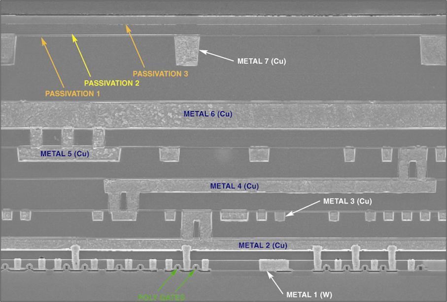
27 Silicon oxide applications Intermetal Oxide Serves as protective/isolation layer between metal lines Passivation layer Interlayer oxide Bonding pad metal M-4 ILD-5 ILD-4 M-3 This oxide is not thermally grown, but is deposited (see further part of this lecture!) Quirk M., Serda J.: Semiconductor Manufacturing Technology, Prentice Hall
28 Chemical Vapor Deposition (CVD) processes Atmospheric Pressure CVD (APCVD) Low Pressure CVD (LPCVD) Plasma Enhanced CVD (PECVD) Metalo-Organic CVD (MOCVD) Atomic Layer Deposition (ALD) Doering R., Nishi Y.: Handbook of semiconductor technology 28


29 APCVD Gases inlet Nitrogen courtain Process parameters: Reactive gases composition Wafer transportation speed Temperature Transport belt To pumps Heater Plummer J.D., Deal M.D., Griffin P.B.: Silicon VLSI technology 29


30 LPCVD Pressure meter Loadlock Quartz furnace with heaters Process parameters: Reactive gases composition Temperature Pressure Time To pumps Si 2 H 2 N 2 SiH 4 Gas distribution system 30


31 PECVD R.F. generator Gas inlet ~ To pumps Process parameters: Reactive gases composition Temperature Pressure Power PLASMA Electrodes Time Electrode geometry Heated table 31
32 The comparison of CVD reactors PROCESS ADVANTAGES DISADVANTAGES APPLICATION APCVD ( C) simplicity of reactor fast deposition rate low temperature processing poor step coverage impurities passivation and isolation oxides (doped, as well as un-doped) cleanliness of deposited high temperature gate and tunneling dielectrics LPCVD ( C) materials homogeneity conformal step coverage a large batch processing processing low deposition rate isolation oxides (doped, as well as un-doped) silicon nitrides poly-silicon PECVD ( C) low temperature processing fast deposition rate good step coverage impurities passivation and isolation oxides M(O)EMS! 32


33 Atomic Layer Deposition (ALD) ALD is a self-limiting, sequential surface chemistry that deposits conformal thin-films of materials onto substrates of varying compositions ALD is similar in chemistry to CVD, except that the ALD reaction breaks the CVD reaction into two half-reactions, keeping the precursor materials separate during the reaction ALD film growth is self-limited and based on surface reactions, which makes achieving atomic scale deposition control possible By keeping the precursors separate throughout the coating process, atomic layer control of film grown can be obtained as fine as ~0.1 angstroms per monolayer 33
34 Exemplary ALD process scheme hafnium dioxide (HfO 2 ) deposition Hf Hf H H H H O O O O M. Godlewski: Technologia Osadzania Warstw Atomowych zastosowania w elektronice, fotowoltaice i optoelektronice Si Si Si Si Si Si Si Si 34
35 Exemplary ALD process scheme hafnium dioxide (HfO 2 ) deposition Hf Hf H H H H O O O O M. Godlewski: Technologia Osadzania Warstw Atomowych zastosowania w elektronice, fotowoltaice i optoelektronice Si Si Si Si Si Si Si Si 35
36 Exemplary ALD process scheme hafnium dioxide (HfO 2 ) deposition H O H H O H H O H Hf Hf O O O O M. Godlewski: Technologia Osadzania Warstw Atomowych zastosowania w elektronice, fotowoltaice i optoelektronice Si Si Si Si Si Si Si Si 36
37 Exemplary ALD process scheme hafnium dioxide (HfO 2 ) deposition Hf Hf H H H H O O O O Hf O Hf O Hf O Hf O O O O M. Godlewski: Technologia Osadzania Warstw Atomowych zastosowania w elektronice, fotowoltaice i optoelektronice Si Si Si Si Si Si Si Si 37
38 Exemplary ALD process scheme hafnium dioxide (HfO 2 ) deposition Hf O Hf O Hf O Hf O O O O Hf O Hf O Hf O Hf O O O O M. Godlewski: Technologia Osadzania Warstw Atomowych zastosowania w elektronice, fotowoltaice i optoelektronice Si Si Si Si Si Si Si Si 38

39 ALD applications High-k dielectric materials HfO 2, Al 2 O 3, TiO 2, ZrO 2 Barrier layers or metal gates: TiN, TaN Huff H.R., Gilmer D.C.: High dielectric constant materials 39
40 Physical Vapor Deposition (PVD) processes Thermal evaporation Ion sputtering Radio Frequency (R.F) magnetron sputtering 40


41 Thermal evaporation Vacuum chamber Support wih wafers Material evaporated Thermal evaporation -> only selected materials, such as: Al, Au, Ag Very high vacuum -> mean particles free path Resistor and evaporated material can react with each other -> impurities To pumps Cheap and easy technology! 41
42 Conductive materials Material Melting temperature [ C] Resistivity [µωcm] Silicon 1412 ~ 10 9 Polysilicon (poly-si) Aluminum (Al) Copper (Cu) Tungsten (W) Titanium (Ti) Tantalum (Ta) Molibdenum (Mo) Platinum (Pt)
43 Thermal evaporation with e-gun Magnets Focused high energy electron beam (>4 kw) High magnetic field which deflects the electron flux -> mass separation and control Target Cooling system -> no impurities from crucible material BUT Problems with the evaporation of compound materials different vapor pressure Cooling system E-gun (hot filament) X-Rays Porosity of layers due to the high energy ions which introduce clusters deposition on the surface 43


44 Evaporation failures The problem with the ensure of homogeneity of evaporated materials on the large surface simultaneously with high layer growth rate Shadow zones Thickness The only option -> to increase the source-substrate lenght BUT reactor geometry/size, as well as high vacuum necessity issues Wafers rotation Increase the area of evaporated material 44
45 Sputtering process In order to glow discharge (plasma ignition) the vacuum cannot be as high as in the case of thermal evaporation Low vacuum -> impurities + low mean free path Small differences of compound materials in comparison to target composition Better process control -> more controllable process parameters BUT optimization Very high equipment cost Increase of ion density -> magnetic field use (magnetron sputtering process) Radio frequency (R.F.) sputtering -> in order to dielectric layers fabrication PLASMA anode cathode electrons + ions - Si wafer Target 45

46 Magnetron sputtering Magnetic field can trap the electrons in the vapor phase Electrons more effectively ionize the gas particles -> ion bombardment of target is increased Lower process temperatures Higher sputtered area Magnets Target N S N PLAZMA Si wafers 46


47 The most common problem Electromigration effect Sze S.M.: Semiconductor devices physics and technology Javey A.: EE143 Characteristic for ALL materials Electrons transfer theirs momentum to material s atom - > atoms flow Critical condition current density At the negative potential possible open At the positive potential possible shortage 47
48 Aluminum and copper materials commonly used for conductive patterns Al Cu Resistivity [µωcm] Electromigration resistance Corrosion resistance Low Low High Medium CVD fabrication Yes No CMP processing Yes Yes 48

49 Copper metallization There are no effective methods for patterns definition by using classical lithography methods (no possibility for dry etching) Damascene technology is the only option Necessity for using barrier layers which eliminate the migration of copper atoms into adjacent semiconductor and dielectric layers There are also needed layers which improve the adhesion level and special layers for copper electroplating (copper fabrication) Plummer J.D., Deal M.D., Griffin P.B.: Silicon VLSI technology 49
50 50


51 Thank you for attention! 51
Semiconductor Manufacturing Technology. Semiconductor Manufacturing Technology
 Semiconductor Manufacturing Technology Michael Quirk & Julian Serda October 2001 by Prentice Hall Chapter 10 Oxidation 2001 2000 by Prentice Hall Diffusion Area of Wafer Fabrication Wafer fabrication (front-end)
Chapter 3 Silicon Device Fabrication Technology
 Chapter 3 Silicon Device Fabrication Technology Over 10 15 transistors (or 100,000 for every person in the world) are manufactured every year. VLSI (Very Large Scale Integration) ULSI (Ultra Large Scale
Chapter 5 Thermal Processes
 Chapter 5 Thermal Processes 1 Topics Introduction Hardware Oxidation Diffusion Annealing Post-Implantation Alloying Reflow High Temp CVD Epi Poly Silicon Nitride RTP RTA RTP Future Trends 2 Definition
Oxidation SMT Yau - 1
 Oxidation Yau - 1 Objectives After studying the material in this chapter, you will be able to: 1. Describe an oxide film for semiconductor manufacturing, including its atomic structure, how it is used
Metallization deposition and etching. Material mainly taken from Campbell, UCCS
 Metallization deposition and etching Material mainly taken from Campbell, UCCS Application Metallization is back-end processing Metals used are aluminum and copper Mainly involves deposition and etching,
EE 330 Lecture 9. IC Fabrication Technology Part II. -Oxidation -Epitaxy -Polysilicon -Planarization -Resistance and Capacitance in Interconnects
 EE 330 Lecture 9 IC Fabrication Technology Part II -Oxidation -Epitaxy -Polysilicon -Planarization -Resistance and Capacitance in Interconnects Review from Last Time Etching Dry etch (anisotropic) SiO
EECS130 Integrated Circuit Devices
 EECS130 Integrated Circuit Devices Professor Ali Javey 9/13/2007 Fabrication Technology Lecture 1 Silicon Device Fabrication Technology Over 10 15 transistors (or 100,000 for every person in the world)
Czochralski Crystal Growth
 Czochralski Crystal Growth Crystal Pulling Crystal Ingots Shaping and Polishing 300 mm wafer 1 2 Advantage of larger diameter wafers Wafer area larger Chip area larger 3 4 Large-Diameter Wafer Handling
Semiconductor Manufacturing Technology. IC Fabrication Process Overview
 Semiconductor Manufacturing Technology Michael Quirk & Julian Serda October 00 by Prentice Hall Chapter 9 IC Fabrication Process Overview /4 Objectives After studying the material in this chapter, you
Review of CMOS Processing Technology
 - Scaling and Integration Moore s Law Unit processes Thin Film Deposition Etching Ion Implantation Photolithography Chemical Mechanical Polishing 1. Thin Film Deposition Layer of materials ranging from
ECSE-6300 IC Fabrication Laboratory Lecture 4: Dielectrics and Poly-Si Deposition. Lecture Outline
 ECSE-6300 IC Fabrication Laboratory Lecture 4: Dielectrics and Poly-Si Deposition Prof. Rensselaer Polytechnic Institute Troy, NY 12180 Office: CII-6229 Tel.: (518) 276-2909 e-mails: luj@rpi.edu http://www.ecse.rpi.edu/courses/s18/ecse
Lecture Day 2 Deposition
 Deposition Lecture Day 2 Deposition PVD - Physical Vapor Deposition E-beam Evaporation Thermal Evaporation (wire feed vs boat) Sputtering CVD - Chemical Vapor Deposition PECVD LPCVD MVD ALD MBE Plating
Fabrication Process. Crystal Growth Doping Deposition Patterning Lithography Oxidation Ion Implementation CONCORDIA VLSI DESIGN LAB
 Fabrication Process Crystal Growth Doping Deposition Patterning Lithography Oxidation Ion Implementation 1 Fabrication- CMOS Process Starting Material Preparation 1. Produce Metallurgical Grade Silicon
Chapter 4. UEEP2613 Microelectronic Fabrication. Oxidation
 Chapter 4 UEEP2613 Microelectronic Fabrication Oxidation Prepared by Dr. Lim Soo King 24 Jun 2012 Chapter 4...113 Oxidation...113 4.0 Introduction... 113 4.1 Chemistry of Silicon Dioxide Formation... 115
Chapter 4 : ULSI Process Integration (0.18 m CMOS Process)
") Chapter : ULSI Process Integration (0.8 m CMOS Process) Reference. Semiconductor Manufacturing Technology : Michael Quirk and Julian Serda (00). - (00). Semiconductor Physics and Devices- Basic Principles(/e)
Chapter : ULSI Process Integration (0.8 m CMOS Process) Reference. Semiconductor Manufacturing Technology : Michael Quirk and Julian Serda (00). - (00). Semiconductor Physics and Devices- Basic Principles(/e)
The Physical Structure (NMOS)
") The Physical Structure (NMOS) Al SiO2 Field Oxide Gate oxide S n+ Polysilicon Gate Al SiO2 SiO2 D n+ L channel P Substrate Field Oxide contact Metal (S) n+ (G) L W n+ (D) Poly 1 3D Perspective 2 3 Fabrication
The Physical Structure (NMOS) Al SiO2 Field Oxide Gate oxide S n+ Polysilicon Gate Al SiO2 SiO2 D n+ L channel P Substrate Field Oxide contact Metal (S) n+ (G) L W n+ (D) Poly 1 3D Perspective 2 3 Fabrication
Physical Vapor Deposition (PVD) Zheng Yang
 Zheng Yang") Physical Vapor Deposition (PVD) Zheng Yang ERF 3017, email: yangzhen@uic.edu Page 1 Major Fabrication Steps in MOS Process Flow UV light Mask oxygen Silicon dioxide photoresist exposed photoresist oxide
Physical Vapor Deposition (PVD) Zheng Yang ERF 3017, email: yangzhen@uic.edu Page 1 Major Fabrication Steps in MOS Process Flow UV light Mask oxygen Silicon dioxide photoresist exposed photoresist oxide
Chapter 7 Polysilicon and Dielectric Film Deposition
 Chapter 7 Polysilicon and Dielectric Film Deposition Professor Paul K. Chu Thin Films in Microelectronics Polycrystalline silicon or polysilicon Doped or undoped silicon dioxide Stoichiometric or plasma-deposited
Lect. 2: Basics of Si Technology
 Unit processes Thin Film Deposition Etching Ion Implantation Photolithography Chemical Mechanical Polishing 1. Thin Film Deposition Layer of materials ranging from fractions of nanometer to several micro-meters
1 MARCH 2017 FILM DEPOSITION NANOTECHNOLOGY
 1 MARCH 2017 FILM DEPOSITION NANOTECHNOLOGY PRESENTATION Pedro C. Feijoo E-mail: PedroCarlos.Feijoo@uab.cat FABRICATION TECHNOLOGIES FOR NANOELECTRONIC DEVICES. PEDRO C. FEIJOO 2 FILM GROWTH Chemical vapor
Figure 2.3 (cont., p. 60) (e) Block diagram of Pentium 4 processor with 42 million transistors (2000). [Courtesy Intel Corporation.
 (e) Block diagram of Pentium 4 processor with 42 million transistors (2000). [Courtesy Intel Corporation.") Figure 2.1 (p. 58) Basic fabrication steps in the silicon planar process: (a) oxide formation, (b) selective oxide removal, (c) deposition of dopant atoms on wafer, (d) diffusion of dopant atoms into exposed
Figure 2.1 (p. 58) Basic fabrication steps in the silicon planar process: (a) oxide formation, (b) selective oxide removal, (c) deposition of dopant atoms on wafer, (d) diffusion of dopant atoms into exposed
EE 5344 Introduction to MEMS. CHAPTER 3 Conventional Si Processing
 3. Conventional licon Processing Micromachining, Microfabrication. EE 5344 Introduction to MEMS CHAPTER 3 Conventional Processing Why silicon? Abundant, cheap, easy to process. licon planar Integrated
Semiconductor Manufacturing Technology. Semiconductor Manufacturing Technology
 Semiconductor Manufacturing Technology Michael Quirk & Julian Serda October 2001 by Prentice Hall Chapter 11 Deposition Film Layers for an MSI Era NMOS Transistor Topside Nitride Pre-metal oxide Sidewall
Thin Films: Sputtering Systems (Jaeger Ch 6 & Ruska Ch 7,) Can deposit any material on any substrate (in principal) Start with pumping down to high
 Can deposit any material on any substrate (in principal) Start with pumping down to high") Thin Films: Sputtering Systems (Jaeger Ch 6 & Ruska Ch 7,) Can deposit any material on any substrate (in principal) Start with pumping down to high vacuum ~10-7 torr Removes residual gases eg oxygen from
Thin Films: Sputtering Systems (Jaeger Ch 6 & Ruska Ch 7,) Can deposit any material on any substrate (in principal) Start with pumping down to high vacuum ~10-7 torr Removes residual gases eg oxygen from
CMOS Technology. Flow varies with process types & company. Start with substrate selection. N-Well CMOS Twin-Well CMOS STI
 CMOS Technology Flow varies with process types & company N-Well CMOS Twin-Well CMOS STI Start with substrate selection Type: n or p Doping level, resistivity Orientation, 100, or 101, etc Other parameters
A discussion of crystal growth, lithography, etching, doping, and device structures is presented in
 Chapter 5 PROCESSING OF DEVICES A discussion of crystal growth, lithography, etching, doping, and device structures is presented in the following overview gures. SEMICONDUCTOR DEVICE PROCESSING: AN OVERVIEW
Silicon Epitaxial CVD Want to create very sharp PN boundary grow one type layer on other in single crystal form High dopant layers on low dopant
 Silicon Epitaxial CVD Want to create very sharp PN boundary grow one type layer on other in single crystal form High dopant layers on low dopant substrate Creates latch up protection for CMOS Buried Epi
Today s Class. Materials for MEMS
 Lecture 2: VLSI-based Fabrication for MEMS: Fundamentals Prasanna S. Gandhi Assistant Professor, Department of Mechanical Engineering, Indian Institute of Technology, Bombay, Recap: Last Class What is
Lecture 22: Integrated circuit fabrication
 Lecture 22: Integrated circuit fabrication Contents 1 Introduction 1 2 Layering 4 3 Patterning 7 4 Doping 8 4.1 Thermal diffusion......................... 10 4.2 Ion implantation.........................
Chapter 3 CMOS processing technology
 Chapter 3 CMOS processing technology (How to make a CMOS?) Si + impurity acceptors(p-type) donors (n-type) p-type + n-type => pn junction (I-V) 3.1.1 (Wafer) Wafer = A disk of silicon (0.25 mm - 1 mm thick),
Thermal Evaporation. Theory
 Thermal Evaporation Theory 1. Introduction Procedures for depositing films are a very important set of processes since all of the layers above the surface of the wafer must be deposited. We can classify
ECE 440 Lecture 27 : Equilibrium P-N Junctions I Class Outline:
 ECE 440 Lecture 27 : Equilibrium P-N Junctions I Class Outline: Fabrication of p-n junctions Contact Potential Things you should know when you leave Key Questions What are the necessary steps to fabricate
EE 330 Lecture 9. IC Fabrication Technology Part 2
 EE 330 Lecture 9 IC Fabrication Technology Part 2 Quiz 8 A 2m silicon crystal is cut into wafers using a wire saw. If the wire diameter is 220um and the wafer thickness is 350um, how many wafers will this
EE 143 CMOS Process Flow
 EE 143 CMOS rocess Flow CT 84 D D G Sub G Sub S S G D S G D S + + + + - MOS Substrate Well - MOS Substrate EE 143 CMOS rocess Flow CT 85 hotoresist Si 3 4 SiO 2 Substrate selection: moderately high resistivity,
Lecture #18 Fabrication OUTLINE
 Transistors on a Chip Lecture #18 Fabrication OUTLINE IC Fabrication Technology Introduction the task at hand Doping Oxidation Thin-film deposition Lithography Etch Lithography trends Plasma processing
Make sure the exam paper has 9 pages total (including cover page)
") UNIVERSITY OF CALIFORNIA College of Engineering Department of Electrical Engineering and Computer Sciences Fall 2010 EE143 Midterm Exam #2 Family Name First name SID Signature Solution Make sure the exam
UNIVERSITY OF CALIFORNIA College of Engineering Department of Electrical Engineering and Computer Sciences Fall 2010 EE143 Midterm Exam #2 Family Name First name SID Signature Solution Make sure the exam
IC/MEMS Fabrication - Outline. Fabrication
 IC/MEMS Fabrication - Outline Fabrication overview Materials Wafer fabrication The Cycle: Deposition Lithography Etching Fabrication IC Fabrication Deposition Spin Casting PVD physical vapor deposition
EE 330 Lecture 8. IC Fabrication Technology Part II. - Oxidation - Epitaxy - Polysilicon - Interconnects
 EE 330 Lecture 8 IC Fabrication Technology Part II - Oxidation - Epitaxy - Polysilicon - Interconnects Review from Last Time MOS Transistor Bulk Source Gate Drain p-channel MOSFET Lightly-doped n-type
Interconnects OUTLINE
 Interconnects 1 Interconnects OUTLINE 1. Overview of Metallization 2. Introduction to Deposition Methods 3. Interconnect Technology 4. Contact Technology 5. Refractory Metals and their Silicides Reading:
Microstructure of Electronic Materials. Amorphous materials. Single-Crystal Material. Professor N Cheung, U.C. Berkeley
 Microstructure of Electronic Materials Amorphous materials Single-Crystal Material 1 The Si Atom The Si Crystal diamond structure High-performance semiconductor devices require defect-free crystals 2 Crystallographic
EE 434 Lecture 9. IC Fabrication Technology
 EE 434 Lecture 9 IC Fabrication Technology Quiz 7 The layout of a film resistor with electrodes A and B is shown. If the sheet resistance of the film is 40 /, determine the resistance between nodes A and
Lecture 10. Metallization / Back-end technology (BEOL)
") Lecture 10 Metallization / Back-end technology (BEOL) Lecture 9: Metallization and BEOL Metallization Technology Evaporation Sputtering Back End Of the Line (BEOL) ITRS Requirements Evolution of Metallization
Lecture 10 Metallization / Back-end technology (BEOL) Lecture 9: Metallization and BEOL Metallization Technology Evaporation Sputtering Back End Of the Line (BEOL) ITRS Requirements Evolution of Metallization
EE 330 Lecture 9. IC Fabrication Technology Part II. -Oxidation -Epitaxy -Polysilicon -Planarization -Resistance and Capacitance in Interconnects
 EE 330 Lecture 9 IC Fabrication Technology Part II -Oxidation -Epitaxy -Polysilicon -Planarization -Resistance and Capacitance in Interconnects Review from Last Time IC Fabrication Technology Crystal Preparation
3. Photolithography, patterning and doping techniques. KNU Seminar Course 2015 Robert Mroczyński
 3. Photolithography, patterning and doping techniques KNU Seminar Course 2015 Robert Mroczyński Critical technology processes Photolithography The aim of this process is to transfer (in the most accurate
EE40 Lec 22. IC Fabrication Technology. Prof. Nathan Cheung 11/19/2009
 Suggested Reading EE40 Lec 22 IC Fabrication Technology Prof. Nathan Cheung 11/19/2009 300mm Fab Tour http://www-03.ibm.com/technology/manufacturing/technology_tour_300mm_foundry.html Overview of IC Technology
ECSE 6300 IC Fabrication Laboratory Lecture 8 Metallization. Die Image
 ECSE 6300 IC Fabrication Laboratory Lecture 8 Metallization Prof. Rensselaer Polytechnic Institute Troy, NY 12180 Office: CII-6229 Tel.: (518) 276-2909 e-mails: luj@rpi.edu http://www.ecse.rpi.edu/courses/s18/ecse
Most semiconductor devices contain at least one junction between p-type and n-type material. These p-n junctions are fundamental to the performance
 Ch. 5: p-n Junction Most semiconductor devices contain at least one junction between p-type and n-type material. These p-n junctions are fundamental to the performance of functions such as rectification,
Thin Films: Sputtering Systems (Jaeger Ch 6 & Ruska Ch 7,) Sputtering: gas plasma transfers atoms from target to substrate Can deposit any material
 Sputtering: gas plasma transfers atoms from target to substrate Can deposit any material") Thin Films: Sputtering Systems (Jaeger Ch 6 & Ruska Ch 7,) Sputtering: gas plasma transfers atoms from target to substrate Can deposit any material on any substrate (in principal) Start with pumping down
Thin Films: Sputtering Systems (Jaeger Ch 6 & Ruska Ch 7,) Sputtering: gas plasma transfers atoms from target to substrate Can deposit any material on any substrate (in principal) Start with pumping down
FABRICATION ENGINEERING MICRO- NANOSCALE ATTHE AND. Fourth Edition STEPHEN A. CAMPBELL. of Minnesota. University OXFORD UNIVERSITY PRESS
 AND FABRICATION ENGINEERING ATTHE MICRO- NANOSCALE Fourth Edition STEPHEN A. CAMPBELL University of Minnesota New York Oxford OXFORD UNIVERSITY PRESS CONTENTS Preface xiii prrt i OVERVIEW AND MATERIALS
EE CMOS TECHNOLOGY- Chapter 2 in the Text
 1 EE 212 FALL 1999-00 CMOS TECHOLOGY- Chapter 2 in the Text In this set of notes we will describe a modern CMOS process flow. In the simplest CMOS technologies, we need to realize simply MOS and MOS transistors
INTEGRATED-CIRCUIT TECHNOLOGY
 INTEGRATED-CIRCUIT TECHNOLOGY 0. Silicon crystal growth and wafer preparation 1. Processing Steps 1.1. Photolitography 1.2. Oxidation 1.3. Layer Deposition 1.4. Etching 1.5. Diffusion 1.6 Backend: assembly,
Alternative Methods of Yttria Deposition For Semiconductor Applications. Rajan Bamola Paul Robinson
 Alternative Methods of Yttria Deposition For Semiconductor Applications Rajan Bamola Paul Robinson Origin of Productivity Losses in Etch Process Aggressive corrosive/erosive plasma used for etch Corrosion/erosion
Oxidation Part 1. By Christopher Henderson
 Oxidation Part 1 By Christopher Henderson In this new series, we will discuss the subject of oxidation. Oxidation is a key aspect of the semiconductor process. The fact that one can easily grow an oxide
IC Fabrication Technology Part III Devices in Semiconductor Processes
 EE 330 Lecture 10 IC Fabrication Technology Part III Metalization and Interconnects Parasitic Capacitances Back-end Processes Devices in Semiconductor Processes Resistors Diodes Review from Last Lecture
ECE321 Electronics I
 ECE321 Electronics I Lecture 19: CMOS Fabrication Payman Zarkesh-Ha Office: ECE Bldg. 230B Office hours: Tuesday 2:00-3:00PM or by appointment E-mail: payman@ece.unm.edu Slide: 1 Miller Effect Interconnect
Copper Interconnect Technology
 Tapan Gupta Copper Interconnect Technology i Springer Contents 1 Introduction 1 1.1 Trends and Challenges 2 1.2 Physical Limits and Search for New Materials 5 1.3 Challenges 6 1.4 Choice of Materials 7
Chemical Vapor Deposition
 Chemical Vapor Deposition ESS4810 Lecture Fall 2010 Introduction Chemical vapor deposition (CVD) forms thin films on the surface of a substrate by thermal decomposition and/or reaction of gas compounds
Introduction to CMOS VLSI Design. Layout, Fabrication, and Elementary Logic Design
 Introduction to CMOS VLSI Design Layout, Fabrication, and Elementary Logic Design CMOS Fabrication CMOS transistors are fabricated on silicon wafer Lithography process similar to printing press On each
Plasma-Enhanced Chemical Vapor Deposition
 Plasma-Enhanced Chemical Vapor Deposition Steven Glenn July 8, 2009 Thin Films Lab 4 ABSTRACT The objective of this lab was to explore lab and the Applied Materials P5000 from a different point of view.
ECE520 VLSI Design. Lecture 7: CMOS Manufacturing Process. Payman Zarkesh-Ha
 ECE520 VLSI Design Lecture 7: CMOS Manufacturing Process Payman Zarkesh-Ha Office: ECE Bldg. 230B Office hours: Wednesday 2:00-3:00PM or by appointment E-mail: pzarkesh@unm.edu Slide: 1 Review of Last
Chemical Vapour Deposition: CVD Reference: Jaeger Chapter 6 & Ruska: Chapter 8 CVD - Chemical Vapour Deposition React chemicals to create a thin film
 Chemical Vapour Deposition: CVD Reference: Jaeger Chapter 6 & Ruska: Chapter 8 CVD - Chemical Vapour Deposition React chemicals to create a thin film layer at the surface Typically gas phase reactions
Semiconductor Device Fabrication
 5 May 2003 Review Homework 6 Semiconductor Device Fabrication William Shockley, 1945 The network before the internet Bell Labs established a group to develop a semiconductor replacement for the vacuum
Semiconductor Technology
 Semiconductor Technology von A bis Z Metallization www.halbleiter.org Contents Contents List of Figures List of Tables II III 1 Metallization 1 1.1 Requirements on metallization........................
Chapter 2 MOS Fabrication Technology
 Chapter 2 MOS Fabrication Technology Abstract This chapter is concerned with the fabrication of metal oxide semiconductor (MOS) technology. Various processes such as wafer fabrication, oxidation, mask
Microelettronica. Planar Technology for Silicon Integrated Circuits Fabrication. 26/02/2017 A. Neviani - Microelettronica
 Microelettronica Planar Technology for Silicon Integrated Circuits Fabrication 26/02/2017 A. Neviani - Microelettronica Introduction Simplified crosssection of an nmosfet and a pmosfet Simplified crosssection
PROCESS FLOW AN INSIGHT INTO CMOS FABRICATION PROCESS
 Contents: VI Sem ECE 06EC63: Analog and Mixed Mode VLSI Design PROCESS FLOW AN INSIGHT INTO CMOS FABRICATION PROCESS 1. Introduction 2. CMOS Fabrication 3. Simplified View of Fabrication Process 3.1 Alternative
ELEC 7364 Lecture Notes Summer Si Oxidation. by STELLA W. PANG. from The University of Michigan, Ann Arbor, MI, USA
 ELEC 7364 Lecture Notes Summer 2008 Si Oxidation by STELLA W. PANG from The University of Michigan, Ann Arbor, MI, USA Visiting Professor at The University of Hong Kong The University of Michigan Visiting
CMOS Fabrication. Dr. Bassam Jamil. Adopted from slides of the textbook
 CMOS Fabrication Dr. Bassam Jamil Adopted from slides of the textbook CMOS Fabrication CMOS transistors are fabricated on silicon wafer Lithography process similar to printing press On each step, different
Fabrication Technology
 Fabrication Technology By B.G.Balagangadhar Department of Electronics and Communication Ghousia College of Engineering, Ramanagaram 1 OUTLINE Introduction Why Silicon The purity of Silicon Czochralski
CSI G SYSTEMS CSI GAS DELIVERY SUPPORT. Chemical Vapor Deposition (CVD)
") This page discusses the CVD processes often used for integrated circuits (ICs). Particular materials are deposited best under particular conditions. Facilitation recommendations are at the bottom of the
This page discusses the CVD processes often used for integrated circuits (ICs). Particular materials are deposited best under particular conditions. Facilitation recommendations are at the bottom of the
Semiconductor Technology
 Semiconductor Technology from A to Z Oxidation www.halbleiter.org Contents Contents List of Figures List of Tables II III 1 Oxidation 1 1.1 Overview..................................... 1 1.1.1 Application...............................
Isolation Technology. Dr. Lynn Fuller
 ROCHESTER INSTITUTE OF TECHNOLOGY MICROELECTRONIC ENGINEERING Isolation Technology Dr. Lynn Fuller Motorola Professor 82 Lomb Memorial Drive Rochester, NY 14623-5604 Tel (585) 475-2035 Fax (585) 475-5041
CHAPTER 4: Oxidation. Chapter 4 1. Oxidation of silicon is an important process in VLSI. The typical roles of SiO 2 are:
 Chapter 4 1 CHAPTER 4: Oxidation Oxidation of silicon is an important process in VLSI. The typical roles of SiO 2 are: 1. mask against implant or diffusion of dopant into silicon 2. surface passivation
Surface Micromachining
 Surface Micromachining Micro Actuators, Sensors, Systems Group University of Illinois at Urbana-Champaign Outline Definition of surface micromachining Most common surface micromachining materials - polysilicon
EE 330 Lecture 12. Devices in Semiconductor Processes
 EE 330 Lecture 12 Devices in Semiconductor Processes Review from Lecture 9 Copper Interconnects Limitations of Aluminum Interconnects Electromigration Conductivity not real high Relevant Key Properties
Microelectronics. Integrated circuits. Introduction to the IC technology M.Rencz 11 September, Expected decrease in line width
 Microelectronics Introduction to the IC technology M.Rencz 11 September, 2002 9/16/02 1/37 Integrated circuits Development is controlled by the roadmaps. Self-fulfilling predictions for the tendencies
PHYS 534 (Fall 2008) Process Integration OUTLINE. Examples of PROCESS FLOW SEQUENCES. >Surface-Micromachined Beam
 Process Integration OUTLINE. Examples of PROCESS FLOW SEQUENCES. >Surface-Micromachined Beam") PHYS 534 (Fall 2008) Process Integration Srikar Vengallatore, McGill University 1 OUTLINE Examples of PROCESS FLOW SEQUENCES >Semiconductor diode >Surface-Micromachined Beam Critical Issues in Process
PHYS 534 (Fall 2008) Process Integration Srikar Vengallatore, McGill University 1 OUTLINE Examples of PROCESS FLOW SEQUENCES >Semiconductor diode >Surface-Micromachined Beam Critical Issues in Process
HOMEWORK 4 and 5. March 15, Homework is due on Monday March 30, 2009 in Class. Answer the following questions from the Course Textbook:
 HOMEWORK 4 and 5 March 15, 2009 Homework is due on Monday March 30, 2009 in Class. Chapter 7 Answer the following questions from the Course Textbook: 7.2, 7.3, 7.4, 7.5, 7.6*, 7.7, 7.9*, 7.10*, 7.16, 7.17*,
Lecture 12. Physical Vapor Deposition: Evaporation and Sputtering Reading: Chapter 12. ECE Dr. Alan Doolittle
 Lecture 12 Physical Vapor Deposition: Evaporation and Sputtering Reading: Chapter 12 Evaporation and Sputtering (Metalization) Evaporation For all devices, there is a need to go from semiconductor to metal.
EE BACKEND TECHNOLOGY - Chapter 11. Introduction
 1 EE 212 FALL 1999-00 BACKEND TECHNOLOGY - Chapter 11 Introduction Backend technology: fabrication of interconnects and the dielectrics that electrically and physically separate them. Aluminum N+ Early
Chapter 2 Manufacturing Process
 Digital Integrated Circuits A Design Perspective Chapter 2 Manufacturing Process 1 CMOS Process 2 CMOS Process (n-well) Both NMOS and PMOS must be built in the same silicon material. PMOS in n-well NMOS
Chapter 2 OVERVIEW OF MEMS
 6 Chapter 2 OVERVIEW OF MEMS 2.1 MEMS and Microsystems The term MEMS is an abbreviation of microelectromechanical system. MEMS contains components ofsizes in 1 micrometer to 1 millimeter. The core element
Lecture 0: Introduction
 Lecture 0: Introduction Introduction Integrated circuits: many transistors on one chip. Very Large Scale Integration (VLSI): bucketloads! Complementary Metal Oxide Semiconductor Fast, cheap, low power
Lecture 030 Integrated Circuit Technology - I (5/8/03) Page 030-1
 Page 030-1") Lecture 030 Integrated Circuit Technology - I (5/8/03) Page 030-1 LECTURE 030 INTEGRATED CIRCUIT TECHNOLOGY - I (References [7,8]) Objective The objective of this presentation is: 1.) Illustrate integrated
Lecture 030 Integrated Circuit Technology - I (5/8/03) Page 030-1 LECTURE 030 INTEGRATED CIRCUIT TECHNOLOGY - I (References [7,8]) Objective The objective of this presentation is: 1.) Illustrate integrated
Mostafa Soliman, Ph.D. May 5 th 2014
 Mostafa Soliman, Ph.D. May 5 th 2014 Mostafa Soliman, Ph.D. 1 Basic MEMS Processes Front-End Processes Back-End Processes 2 Mostafa Soliman, Ph.D. Wafers Deposition Lithography Etch Chips 1- Si Substrate
A Novel Low Temperature Self-Aligned Field Induced Drain Polycrystalline Silicon Thin Film Transistor by Using Selective Side-Etching Process
 Chapter 3 A Novel Low Temperature Self-Aligned Field Induced Drain Polycrystalline Silicon Thin Film Transistor by Using Selective Side-Etching Process 3.1 Introduction Low-temperature poly-si (LTPS) TFTs
THE PENNSYLVANIA STATE UNIVERSITY SCHREYER HONORS COLLEGE DEPARTMENT OF ENGINEERING SCIENCE AND MECHANICS
 THE PENNSYLVANIA STATE UNIVERSITY SCHREYER HONORS COLLEGE DEPARTMENT OF ENGINEERING SCIENCE AND MECHANICS A STUDY OF BIASED TARGET ION BEAM DEPOSITED DIELECTRIC OXIDES FELIX ARONOVICH FALL 2013 A thesis
ME 141B: The MEMS Class Introduction to MEMS and MEMS Design. Sumita Pennathur UCSB
 ME 141B: The MEMS Class Introduction to MEMS and MEMS Design Sumita Pennathur UCSB Outline today Introduction to thin films Oxidation Deal-grove model CVD Epitaxy Electrodeposition 10/6/10 2/45 Creating
CSCI 4974 / 6974 Hardware Reverse Engineering. Lecture 5: Fabrication processes
 CSCI 4974 / 6974 Hardware Reverse Engineering Lecture 5: Fabrication processes QUIZ 3: CMOS layout Quiz Discussion Rationale If you know how something is put together, you can figure out how to take it
Lecture 8. Deposition of dielectrics and metal gate stacks (CVD, ALD)
") Lecture 8 Deposition of dielectrics and metal gate stacks (CVD, ALD) Thin Film Deposition Requirements Many films, made of many different materials are deposited during a standard CMS process. Gate Electrodes
Lecture 8 Deposition of dielectrics and metal gate stacks (CVD, ALD) Thin Film Deposition Requirements Many films, made of many different materials are deposited during a standard CMS process. Gate Electrodes
Complexity of IC Metallization. Early 21 st Century IC Technology
 EECS 42 Introduction to Digital Electronics Lecture # 25 Microfabrication Handout of This Lecture. Today: how are Integrated Circuits made? Silicon wafers Oxide formation by growth or deposition Other
Technology. Semiconductor Manufacturing. Hong Xiao INTRODUCTION TO SECOND EDITION SPIE PRESS
 INTRODUCTION TO Semiconductor Manufacturing Technology SECOND EDITION Hong Xiao TECHNISCHE INFORMATIONSBiBUOTHEK UNIVERSITATSBIBLIOTHEK HANNOVER SPIE PRESS Bellingham,Washington USA Contents Preface to
ELEC 3908, Physical Electronics, Lecture 4. Basic Integrated Circuit Processing
 ELEC 3908, Physical Electronics, Lecture 4 Basic Integrated Circuit Processing Lecture Outline Details of the physical structure of devices will be very important in developing models for electrical behavior
Lecture 19 Microfabrication 4/1/03 Prof. Andy Neureuther
 EECS 40 Spring 2003 Lecture 19 Microfabrication 4/1/03 Prof. ndy Neureuther How are Integrated Circuits made? Silicon wafers Oxide formation by growth or deposition Other films Pattern transfer by lithography
UNIT 4. By: Ajay Kumar Gautam Asst. Prof. Dev Bhoomi Institute of Technology & Engineering, Dehradun
 UNIT 4 By: Ajay Kumar Gautam Asst. Prof. Dev Bhoomi Institute of Technology & Engineering, Dehradun Syllabus METALLIZATION: Applications and choices, physical vapor deposition, patterning, problem areas.
EE 143 FINAL EXAM NAME C. Nguyen May 10, Signature:
 INSTRUCTIONS Read all of the instructions and all of the questions before beginning the exam. There are 5 problems on this Final Exam, totaling 143 points. The tentative credit for each part is given to
Process Integration. MEMS Release Techniques Sacrificial Layer Removal Substrate Undercut
 Process Integration Self-aligned Techniques LOCOS- self-aligned channel stop Self-aligned Source/Drain Lightly Doped Drain (LDD) Self-aligned silicide (SALICIDE) Self-aligned oxide gap MEMS Release Techniques
Process Integration. NMOS Generic NMOS Process Flow. CMOS - The MOSIS Process Flow
 Process Integration Self-aligned Techniques LOCOS- self-aligned channel stop Self-aligned Source/Drain Lightly Doped Drain (LDD) Self-aligned silicide (SALICIDE) Self-aligned oxide gap MEMS Release Techniques