Post installed rebar connections
|
|
|
- Phoebe Russell
- 6 years ago
- Views:
Transcription

1 Post installed rebar connections Post installed rebar connections Basics of post installed rebar connections Hilti HIT-RE 500 post installed rebar Hilti HIT-HY 150 post installed rebar Hilti HIT- HY 150 MAX post installed rebar 1 /


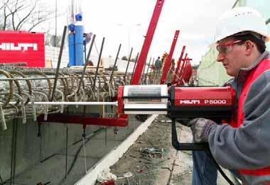
2 Basics of post installed rebar connections Basics of post installed rebar connections 1 Applications 1.1 Advantages of post-installed rebar connections With the use of the Hilti-HIT injection systems it is possible to connect new reinforcement to existing structures with maximum confidence and flexibility. design flexibility reliable like cast in horizontal, vertical and form work simplification defined load characteristics overhead simple, high confidence application 1.2 Application examples Post installed rebar connections are widely used within the construction industry in a wide range of applications, which vary from new construction projects, to structure upgrades and infrastructure requalifications. Post-installed rebar connections in new construction projects Diaphragm walls Slab connections Misplaced bars Vertical/horizontal connections / 2009


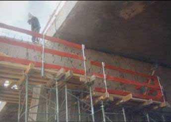
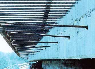
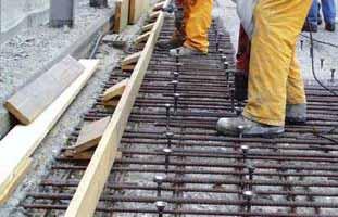
3 Basics of post installed rebar connections Post-installed rebar connections in structure updgrades Wall strenghtening New slab constructions Joint strenghtening Cantilevers/balconies Post-installed rebar connections in infrastructure requalifications Slab widening Structural upgrade Slab strenghtening Side-walk upgrade 1 /
4 Basics of post installed rebar connections 2 Rebar basics 2.1 Definition of rebar Rebar is standing for REinforcement BAR. At Hilti the word is used for a reinforcement bar inserted into a borehole filled with Hilti HIT in reinforced concrete structures, in other words for post-installed reinforcement. Post-installed reinforcement can be split up into four different main applications: Good detailing practice Shear studs Rebar as structural rebar Rebar as an anchor In the course of the Anchor FTM the focus will be on the last two types of applications. Chapter 3, Adhesive Anchoring Systems, deals with rebar as an anchor. The current chapter focuses on rebar as structural rebar, where the reinforcement is purely loaded in the longitudinal direction. l v l 0 l bd 2 / 3 l bd 10 d s Figure 2.1: Example of structural rebar application Structural rebar is characterized by very high loads. The reinforcement is often loaded up to steel yielding. The concrete structure (connection) shows a good serviceability. The deformations are small and due to this the crack width and therefore the influences by the environment (corrosion) are limited. The concrete connections behave as a monolithic structure or in other words as if the concrete was poured in one go. The high loads which can occur in either the anchorage or the splice can lead to an embedment length up to 15 till 80 times the diameter of the reinforcement. The design can be done according to two design concepts; Structural code, for instance EC2 EN :2004 chapter 8.4 anchorage of longitudinal reinforcement, based on approvals (e.g. ETA according to EOTA TR023) See paragraph 4 of this chapter for an overview of the approvals Hilti HIT-Rebar design concept, based on the American Standard (ACI ), where the allowable bond stress is controlled by splitting / spalling behaviour. For this type of connections an engineer is usually involved in the design / 2009
5 Basics of post installed rebar connections 2.2 Rebar as an anchor Rebar as an anchor is characterized by the fact it is not possible to splice the reinforcement (due to e.g. lack of useable reinforcement). The loads are typically smaller as in the case of structural rebar and the serviceability is slightly lower. The anchor failure modes like concrete cone failure or combined concrete cone and pull-out failure are considered in this application according to standard anchor design. For this type of connections an engineer is usually involved in the design. 2.3 Cast-in ribbed bars Generally, for load transfer in reinforced concrete only tensile or compressive forces in bars are considered. For ribbed bars, the load transfer in concrete is governed by the bearing of the ribs against the concrete (figure 2.3.a). The force reaction in the concrete is assumed to form a compressive strut in the direction of 45. For higher bond stress values, the concentrated bearing forces in front of the ribs cause the formation of cone-shaped cracks starting at the crest of the ribs. The resulting concrete keys between the ribs transfer the bearing forces into the surrounding concrete, but the wedging action of the ribs remains limited. In this stage the displacement of the bar with respect to the concrete (slip) consists of bending of the keys and crushing of the concrete in front of the ribs. The bearing forces, which are inclined with respect to the bar axis, can be decomposed into directions parallel and perpendicular to the bar axis. The sum of the parallel components equals the bond force, whereas the radial components induce circumferential tensile stresses in the surrounding concrete, which may result in longitudinal radial (splitting / spalling) cracks. Figure 2.3.a: Load transfer from ribbed bars into concrete Two failure modes can be considered: a) Bond failure (fig. 2.3.a): If the confinement (concrete cover, transverse reinforcement) is sufficient to prevent splitting of the concrete cover, bond failure is caused by pull-out of the bar. In that case the concrete keys are sheared off and a sliding plane around the bar is created. Thus, the force transfer mechanism changes from rib bearing to friction. The shear resistance of the keys can be considered as a criterion for this transition. It is attended by a considerable reduction of the bond stress. Under continued loading the sliding surface is smoothed due to wear and compaction, which will result in a further decrease of the bond stress, similar to the case of plain bars. 1 /

.")
6 Basics of post installed rebar connections b) Splitting failure (fig. 2.3.b): If the radial cracks propagate through the entire cover, bond splitting failure is decisive. In that case the maximum bond stress follows from the maximum concrete confinement, which is reached when the radial cracks have penetrated the cover for about 70%. Further crack propagation results in a decrease of the confining stresses. At reaching the outer surface these stresses are strongly reduced, which results in a sudden drop of the bond stress. Figure 2.3.b 2.4 Lapped bar splices Model for load transfer at lapped bar splices The load transfer between bars is performed by means of compressive struts in the concrete (fig ). A 45 truss model is assumed. The resulting perpendicular forces act in a similar way as the splitting forces. The splitting forces normally are taken up by the transverse reinforcement. Small splitting forces are attributed to the tensile capacity of the concrete. The amount of the transverse or tie reinforcement necessary is specified in the design codes. Figure 2.4.1: Load transfer at lap splices Influence of spacing and cover on splitting and spalling of concrete In most cases the reinforcement bars are placed close to the surface of the concrete member to achieve good crack distribution and economical bending capacity. For splices at wide spacing (normally in slabs, fig a), the bearing capacity of the concrete depends only on the thickness of the concrete cover. At narrow spacing (normally in beams, fig b) the bearing capacity depends on the spacing and on the thickness of the cover. In the design codes the reduction of bearing capacity of the cover is taken into account by means of multiplying factors for the splice length. Figure a Figure b Bond behaviour of post-installed ribbed bars The load transfer for post-installed bars is similar to cast in bars if the stiffness of the overall load transfer mechanism is similar to the cast-in system. The efficiency depends on the strength / 2009
7 Basics of post installed rebar connections of the adhesive mortar against the concentrated load near the ribs and on the capacity of load transfer at the interface of the drilled hole. In many cases the bond values of post-installed bars are higher compared to cast in bars due to better performance of the adhesive mortar. But for small edge distance and/or narrow spacing splitting or spalling forces become decisive due to the low tensile capacity of the concrete. 3 Design basics 3.1 Rebar design methods Post-installed reinforcement connections can basically be designed in compliance with the national codes. Hilti is offering two design methods of which one is based on the Eurocode 2 (EC2 EN :2004) and the other one on the American Standard (ACI ). The most important characteristics will be explained in the following paragraphs. 3.2 Rebar design according to EC2/ETA approach The new technical report EOTA TR 023 (Assessment of post-installed rebar connections) establishes a common method to qualify chemical anchors in compliance with EC2. Chemical anchors must comply with a predefined step-diagram for the different concrete classes (Figure 3.2: Chemical anchors without limitations). In general it shall be shown by the tests as described in the TR 023 that the post-installed rebar systems can develop the same design values of bond resistance with the same safety margin as cast-in place rebars according to EC2. In EC2 no requirements for testing are given, but the values for fbd are published. These values are valid for worst case conditions, minimum concrete cover, minimum spacing and minimum transverse reinforcement. In Figure 3.2 a comparison is given which bond resistance in the tests and evaluation according TR 023 have to be reached (on y- axis) to show equivalence with the values f bd (on x- axis). A European Technical Approvals according to the EOTA TR023 allows a design according to EC2. However a design for fire resistance, fatigue, dynamic or seismic loading are excluded. The ETA for Rebar proves that approved systems are robust and durable. Influences of bad cleaning, wet holes, creep, freeze/thaw, durability, corrosion resistance, installation directions are tested within the approval. The post-installed rebar connections assessed according to TR 023 shall be designed as straight cast-in reinforcement according to EC2 using the values of the design bond resistance fbd for deformed bars. The definition of the bond region in EC2 is valid also for post-installed reinforcement. The conditions in EC2 concerning detailing (e.g. concrete cover in respect to bond and corrosion resistance, bar spacing, transverse reinforcement) shall be complied with. 1 /
8 Basics of post installed rebar connections Figure 3.2: Chemical anchors without limitations from EOTA TR023 The following additional provisions have to be taken into account. To prevent damage of the concrete during drilling the following requirements have to be met: c min = ,06l v 2d s (mm) for hammer drilled holes, with ds being the diameter of the rebar c min = ,08l v 2d s (mm) for compressed air drilled holes The factors 0,06 and 0,08 take into account the possible deviations during the drilling process. This value might be smaller if special drilling aid devices are used. Minimum clear spacing between two post-installed rebars a = 40 mm 4d s To account for potentially different behaviour of post-installed and cast-in rebars in cracked concrete, in general, the minimum embedment length l b,min and l 0,min given in EC2 for anchorages and overlap splices shall be increased by a factor of 1,5. This increase may be neglected if it can be shown that the bond strength of the selected postinstalled rebars and cast-in rebars in cracked concrete (w = 0,3 mm) is similar. In this case the influence of cracks openings (crack movement tests) can be neglected because for rebar connections several rebars are present (redundant fastening) and not all of the rebars will be situated in a longitudinal crack. The transfer of shear forces between new and old concrete shall be designed according to EC2. See also paragraph 3.4 strut-and-tie model. The reader is referred to the paragraph 4 EC2 Design for more detail about this design concept / 2009
9 Basics of post installed rebar connections 3.3 Hilti HIT-Rebar design and ACI approach The American Standard ACI (American Concrete Institute) gives an explicit formula for the design of anchorages and splices that considers splitting and spalling as a function of concrete cover and bar spacing. This function is adapted and extended for post-installed reinforcement for the Hilti HIT-Rebar design concept. The embedment length of an anchorage or splice is defined as a function of concrete strength, the bar diameter, the minimum edge distance or spacing and a coefficient taking into account the transverse reinforcement. In figure 3.3 a typical design bond stress f bd curve as a function of the minimum edge distance/spacing distance, c d is shown for a concrete class C20/25 and for a rebar with a diameter of 12 mm (EC2/ETA approach). In this figure the equivalent design bond stresses resulting from the ACI and the EC2/ETA approaches are plotted to illustrate the two methods (the design bond stresses shown in the figure shall not be used for design purposes). The reduction of anchoring length allowed by ACI and EC2/ETA in specific conditions can be assimilated to an increase of the equivalent design bond stress if c d changes within certain limits. The equivalent design bond stress is defined by an inclined line and it increases with larger values of c d. The increase in the design bond stress is limited by the maximum pull-out bond stress, which is a value which is given by the standards in the case of a cast-in reinforcement. For post-installed reinforcement, the maximum design bond stress is a function of the bonding agent and not necessarily equals that of cast-in bars. Thus, the limitation for bond failure in the code has been replaced by the specific design bond stress of the bonding agent for the specific application conditions and the splitting function has been adapted according to the tests. fbd N/mm N/mm c ACI approach d,min c d C20/25, Ø = 12 mm EC2/ETA approach c d = min(a/2, c, c 1 ) Figure 3.3: equivalent design bond stress f bd as a function of c d., derived from reduction of anchoring lenght according to ACI and EC2/ETA. 1 /
10 Basics of post installed rebar connections Interaction of concrete cover and transverse reinforcement (splitting reinforcement) Tests show that transverse reinforcement improves the splitting capacity. Transverse reinforcement can be taken into account by adding a substitute value for the cover. The ACI code explicitly takes into account the influence of transverse reinforcement able to prevent splitting by means of the transverse reinforcement index K tr. f bd = f ck c + K tr 4 φ ξ ; A tr f yt K tr = ; s n c + K tr φ 2.5 for cast - in bars with: A tr total cross-sectional area of all transverse reinforcement that is within the spacing s and that crosses the potential plane of splitting through the reinforcement being developed [mm 2 ] f yt yield strength of transverse reinforcement [N/mm 2 ] s maximum spacing of transverse reinforcement within b, center to center [mm] n number of bars being developed along the plane of splitting [-] ξ substitute for various adjustment factors Hilti HIT-Rebar design concept c + K for tr 2. 5 (post-installed reinforcement and cast-in reinforcement): φ f bd f ck c + K = 4 γ φ tr for c + K tr > 2. 5 φ (bonded-in bars only): f bd = f ck c + K tr γ φ where: f bd design bond strength φ nominal bar size f ck characteristic concrete cylinder strength c = c d = min(a/2, c, c 1 ) K tr see above γ bar size factor For more detailed Information see: Kunz, J.; Münger, F.: Splitting- and bond failure of post-installed rebar splices and anchoring. ; Bond in Concrete from research to standards, Proceedings of the 3rd International Symposium held at the Budapest University of Technology and Economics, Budapest, Hungary, 20 to 22 November 2002, p (Copy available from Hilti Technical Service) / 2009
, EC2: EN 1992-1- 1:2004}.")
11 Basics of post installed rebar connections 3.4 Strut-and-tie model The tensile bearing capacity of concrete is very low compared to its compressive strength. For this reason tensile forces are attributed to the steel reinforcement of the concrete member. The reinforcement should be adequately anchored in the nodes {Clause 6.5.3(2), EC2: EN :2004}. Joint to be roughened Crack limitation Tension cord Figure 3.4: Strut-and-tie-model Compression cord and strut (concrete) Tension ties A strut-and-tie model is used to calculate the load path in reinforced concrete members. Where a non-linear strain distribution exists (e.g. supports) strut-and-tie models may be used {Clause 6.5.1(1), EC2: EN :2004}. Strut-and-tie models consist of struts representing compressive stress fields, of ties representing the reinforcement and of the connecting nodes. The forces in the elements of a strut-and-tie model should be determined by maintaining the equilibrium with the applied loads in ultimate limit state. The ties of a strut-and-tie model should coincide in position and direction with the corresponding reinforcement {Clause 5.6.4, EC2: EN :2004 Analysis with strut and tie models}. 3.5 Joint to be roughened The model of inclined compressive struts is used to transfer the shear forces through the construction joint at the interface between concrete cast at different times. Therefore a rough interface is required to provide sufficient cohesion in the construction joint {Clause 6.2.5(2), EC2: EN :2004}. Rough means a surface with at least 3 mm roughness (R t > 3 mm), achieved by raking, exposing the aggregate or other methods giving an equivalent behaviour. 3.6 Anchorage of reinforcement The reinforcement has to be anchored at places where it is no longer needed. These situations may occur: when the load path of the tensile force has ended (e.g. support, figure 3.6.a) at curtailment of reinforcement (see figure 3.6.b) compression bar anchorage (see figure 3.6.c). 1 /

 is limited to a value depending on the surface characteristics of the reinforcement, the tensile strength of the concrete and confinement of")


12 Basics of post installed rebar connections Figure 3.6.a: Support, truss Figure 3.6.b: Tensile force has ended Figure 3.6.c: Compression 3.7 Lapped splice of reinforcement Lapped splices are used to achieve continuity in the tensile tie of the truss model at construction joints. The load from one bar to the other is transferred by means of compressive struts in the concrete. A 45 -truss model is assumed. The resulting splitting force (design bond stress) is limited to a value depending on the surface characteristics of the reinforcement, the tensile strength of the concrete and confinement of surrounding concrete. This depends on sufficient concrete cover, spacing of bar, transverse pressure and by the transverse reinforcement {Clause 6.6, EC2: EN :2004}. Figure 3.7: Lapped splice 4 EC2 design 4.1 General The actual position of the reinforcement in the existing structure shall be determined on the basis of the construction documentation and taken into account when designing. The transfer of shear forces between new concrete and existing structure shall be designed according to EC2 EN :2004. See also paragraph 3.4 Strut-and-tie model The joints for concreting must be roughened to at least such an extent that aggregate protrude. See also paragraph 3.5 Joint to be roughened. The design of post-installed rebar connections and determination of the internal section forces to be transferred in the construction joint shall be verified in accordance with EC2 EN :2004. When ascertaining the tensile force in the rebar, allowance shall be made for the statically effective height of the bonded-in reinforcement. See also paragraph 5.2 Example with overlap joint / 2009
13 Basics of post installed rebar connections 4.2 Determination of the basic anchorage length The calculation of the required anchorage length shall take into consideration the type of steel and bond properties of the reinforcement. The required basic anchorage length l b,rqd shall be determined in accordance with clause 8.4.3, EC2: EN :2004: l b,rqd = (d s / 4) (σ sd / f bd ) with: d s = diameter of the rebar σ sd = calculated design stress of the rebar f bd = design value of bond strength according to corresponding ETA, in consideration of the coefficient related to the quality of bond conditions and, of the coefficient related to the bar diameter and of the drilling technique. Refer to the relevant approval or technical data sheet for details. 4.3 Determination of the design anchorage length The required design anchorage length l bd shall be determined in accordance with clause 8.4.4, EC2: EN :2004: l bd = α 1 α 2 α 3 α 4 α 5 l b,rqd l b,min Where α 1, α 2, α 3, α 4 and α 5 are coefficients given in Table 4.1. α 1 is for the effect of the form of the bars assuming adequate cover (post-installed reinforcement is always straight) α 2 is for the effect of concrete minimum cover α2 = 1 0,15 ( c d d0 )/d0 straight bars; min ( a/2;c ;c) c d = 1 With no edge distance, α 2 = 0,7 if the spacing given in the table below are fulfilled: d s (mm) Spacing (mm) a (mm) α 3 is for the effect of confinement by transverse reinforcement α 4 is for the influence of one or more welded transverse bars along the design anchorage length l bd. (no welded transverse reinforcement possible with postinstalled reinforcement) α 5 is for the effect of the pressure transverse to the plane of splitting along the design anchorage length. The product (α 2 α 3 α 5 ) 0,7 1 /
14 Basics of post installed rebar connections l b,rqd = according to section 5.2 l b,min = minimum anchorage length according to clause 8.4.4, EC2: EN :2004 = max {0.3 l b,rqd ; 10d s ; 100 mm} under tension = max {0.6 l b,rqd ; 10d s ; 100 mm} under compression (Please note that the minimum anchorage length may be increased by factor 1,5 according to EOTA TR023, 4.2. Refer to the relevant approval or technical data sheet for details.) Table 4.1: Values of α 1, α 2, α 3, α 4 and α 5 coefficients Influencing factor Type of anchorage Reinforcement bar In tension In compression Shape of bars Straight α 1 = 1.0 α 1 = 1.0 Concrete cover Straight α 2 = (c d α 2 = 1.0 ø)/ø Confinement by Straight α 3 = 1 Kλ α 3 = 1.0 transverse reinforcement Confinement by welded transverse Straight α 4 = 1.0 α 4 = 1.0 reinforcement Confinement by transverse pressure where: λ Straight α 5 = p = (ΣA st - ΣA st,min )/ A s ΣA st cross-sectional area of the transverse reinforcement along the design anchorage length lbd ΣA st,min cross-sectional area of the minimum transverse reinforcement = 0.25 As for beams and 0 for slabs As area of a single anchored bar with maximum bar diameter K values shown in Figure 4.10 p transverse pressure [MPa] at ultimate limit state along lbd - Figure 4.3 : Values of K for beams and slabs 4.4 Overlap joints Forces are transmitted from one bar to another by lapping the bars. The detailing of laps between bars shall be such that: - the transmission of the forces from one bar to the next is assured - spalling of the concrete in the neighbourhood of the joints does not occur - large cracks which affect the performance of the structure do not occur / 2009
15 Basics of post installed rebar connections Laps between bars should not be located in areas of high moments / forces (e.g. plastic hinges) and at any section normally be arranged symmetrically. The arrangement of lapped bars should comply with Figure 4.4. The clear distance between lapped bars should be 4ø and 50 mm, otherwise the lap length should be increased by a length equal to the clear space where it exceeds 4ø or 50 mm. 3ø Figure 4.4: Adjacent laps The required design lap length l 0 shall be determined in accordance with clause 8.7.3, EC2: EN :2004: l 0 = α 1 α 2 α 3 α 5 α 6 l b,rqd l 0,min with: l b,rqd = according to section 4.2 l 0,min = minimum lap length = max {0.3α 6 l b,rqd ; 15d s ; 200 mm} (Please note that the minimum anchorage length may be increased by factor 1,5 according to EOTA TR023, 4.2. Refer to the relevant approval or technical data sheet for details.) Values of α 1, α 2, α 3 and α 5 may be taken from Table 4.1; however, for the calculation of α 3, ΣA st,min should be taken as 1,0 A s (σ sd /f yd ), with A s = area of one lapped bar. α 6 = (ρ 1 /25)0.5 but neither not exceeding 1,5 nor less than 1,0, where ρ 1 is the percentage of reinforcement lapped within 0.65l 0 from the centre of the lap length considered. Values of α 6 are given in Table 4.2. (Note: For postinstalled rebar applications α 6 = 1,5 for the majority of the cases) Table 4.2: Values of the coefficient α 6 Percentage of lapped bars < 25% 33% 50% > 50% relative to the total crosssection area α 6 1 1,15 1,4 1,5 4.5 Embedment depth for overlap joints Overlap joint for rebars: For calculation of the effective embedment depth of overlap joints the concrete cover at end-face of the postinstalled rebar c1 shall be considered: l v l 0 + c 1 with: l 0 = required lap length according to paragraph 4.4. c 1 = concrete cover at end-face of bonded-in rebar. See Figure /
16 Basics of post installed rebar connections Figure 4.5: Concrete cover c 1 If the clear distance between the overlapping bars is greater than 4d s the lap length shall be enlarged by the difference between the actual clear distance and 4d s. 4.6 Concrete cover The minimum concrete cover required for bonded-in rebars is shown in the ETA approvals in relation to the drilling method and the hole tolerance. Furthermore the minimum concrete cover given in clause , EC2: EN : 2004 shall be observed. 4.7 Transverse reinforcement The requirements of transverse reinforcement in the area of the post-installed rebar connection shall comply with clause 8.7.4, EC2: EN : Connection joint In case of a carbonated surface of the existing concrete structure the carbonated layer shall be removed in the area of the post installed rebar connection with a diameter of d s + 60 mm prior to the installation of the new rebar. The depth of concrete to be removed shall correspond to at least the minimum concrete cover for the respective environmental conditions in accordance with EC2: EN : / 2009

17 Basics of post installed rebar connections 5 Design examples 5.1 Anchorage: End support of slab, simply supported h = 300 d = 260 a 1 = 130 a l = 260 l n = 6,50 m h = 300 slab: l n = 6,50 m, Q k = 5 kn/m 2,h = 300 mm,d = 260 mm wall: h = 300 mm Concrete strength class: C20/25, dry concrete Properties of reinforcement: f yk = 500 N/mm2 Short-term/long-term temperature is 20 C Fire resistance: F90 (90 minutes) Loads: G d = 1,35 x 7,5 = 10,1 kn/m²; Q d = 1,5 x 5,0 = 7,5 kn/m² = 17,6 kn/m² Structural analysis (design forces) based on l eff : M Sd = 17,6 x 6,762 / 8 = 100,5 knm/m V Sd = 17,6 x (6,76 / 2) = 59,5 kn/m Bottom reinforcement required at mid span: A s,req = 100,5 x 1,15 / (0,26 x 0,9 x 0,5) = 988 mm²/m reinforcement provided: 16, s = 200 mm; A s,prov = 1010 mm²/m Bottom reinforcement at support: A s,min = 0,4 x 1 x 2,2 x 150 x 1000 / 500 = 264 mm²/m {Clause 7.3.2(2), EC2: EN :2004} A s,min = 0,50 x 988 = 494 mm 2 /m {Clause (1), EC2: EN :2004} {Clause (4), EC 2: EN :2004} A s,min = 0,25 x 988 = 247 mm²/m {Clause (1), EC2: EN :2004} A s,req = 59,5 x 1 / 0,9 x 1,15 / 0,5 = 152 mm 2 /m (al =d) {Clause (2), EC2: EN :2004} Decisive is 494 mm²/m reinforcement provided: 12, s = 200 mm; A s,prov = 565 mm²/m a) Anchorage according to European Technical Approval (ETA) 08/0105, Post-installed rebar connections with Hilti injection mortar HIT-RE 500 Determination of the basic anchorage length The required basic anchorage length l b,rqd shall be determined in accordance with EC2: EN :2004, section 8.4.3: l b,rqd = (d s / 4) x (σ sd / f bd ) with: d s = diameter of the rebar = 12 mm σ sd = calculated design stress of the rebar = (494 / 565) x (500 / 1,15) = 380 N/mm² f bd = design value of bond strength according to corresponding ETA = 2,3 N/mm² l b,rqd = (12 / 4) x (380 / 2,3) = 496 mm 1 /
/ø α 2 is for the effect of concrete minimum cover 0,7 1,0 a = 200 12 = 188 mm")
18 Basics of post installed rebar connections Determination of the design anchorage length The required design anchorage length l bd shall be determined in accordance with EC2: EN :2004, section 8.4.4: l bd = α 1 α 2 α 3 α 4 α 5 l b,rqd l b,min with: l b,rqd as above α 1 = 1,0 for straight bars α 2 = 1 0,15(c d ø)/ø α 2 is for the effect of concrete minimum cover 0,7 1,0 a = = 188 mm a/2 = 94 mm with c1 and c > 94 mm ø = 12 mm α 2 = 0,7 Straight bars, c d = min (a/2, c 1, c) α 3 = 1,0 because of no transverse reinforcement α 4 = 1,0 because of no welded transverse reinforcement α 5 = 1,0 influence of transverse pressure is neglected in this example l bd = 0,7 x 496 = 347 mm 2/3l bd = 231 mm 230 mm l b,min = minimum anchorage length {Clause 8.4.4(1), EC2: EN :2004} = max {0,3 x 496; 10 x 12; 100} = 149 mm b) Anchorage according to Hilti HIT-Rebar design method (splitting): Reinforcement provided: 12, s = 200 mm; A s,prov = 565 mm²/m Mortar: Hilti HIT-RE 500 F Sd = 494 x 0,5 / 1,15 = 214,8 kn/m Steel: F Rd = 5 x (f yk x π x 2 x ¼) / у s = 245,9 kn/m > 214,8 kn/m ok Concrete (splitting) / Mortar (pull-out): Due to large edge distances in all directions (confined concrete) the failure mode splitting of concrete is not becoming decisive, but the pull out failure mode: f bd = 6.9 N/mm 2 F Rd = n(l bd x x π x f bd ) = 5(l bd x 12 x π x 6.9) = kn/m l bd = 165 mm l b,min = 120 mm (10 x ) ok Fire resistance: Fire rating class F 90 (90 min.) (design table see paragraph 4.7): F st,req = 0,6 x 66,1 = 39,7 kn/m = 7,9 kn/bar {Clause (4) and (5), EC2: ENV :1995} Hilti HIT-RE 500: 12 l inst = 14,5 cm; F s,t = 6,02 kn l inst = 18 cm; F s,t = 15,0 kn / 2009
19 Basics of post installed rebar connections Intermediate values may be interpolated linearly: l inst = 16,5 cm; F s,t = 11,2 kn/bar > 7,9 kn/bar l inst = 165 mm Top reinforcement 300 d = 260 a 1 = 130 a l = 260 l n = 6.50 m h = 300 Top reinforcement at support: Minimum reinforcement: 25% of bottom steel required at mid-span {Clause (2), EC2: EN :2004} A s,req = 0,25 x 988 = 247 mm 2 /m A s,min = 0,4 x 1 x 2,2 x 150 x 1000 / 500 = 264 mm 2 /m {Clause 7.3.2(2), EC2: EN :2004} Decisive is 264 mm²/m reinforcement provided: 12, s = 300 mm; A s,prov = 377 mm²/m a) Anchorage according to European Technical Approval (ETA) 08/0105, Post-installed rebar connections with Hilti injection mortar HIT-RE 500 Determination of the basic anchorage length The required basic anchorage length l b,rqd shall be determined in accordance with EC2: EN :2004, section 8.4.3: l b,rqd = (d s / 4) x (σ sd / f bd) with: d s = diameter of the rebar = 12 mm σ sd = calculated design stress of the rebar = (264 / 377) x (500 / 1.15) = 304 N/mm² f bd = design value of bond strength according to corresponding ETA = 2,3 N/mm² l b,rqd = (12 / 4) x (304 / 2,3) = 397 mm Determination of the design anchorage length The required design anchorage length l bd shall be determined in accordance with EC2: EN :2004, section 8.4.4: l bd = α 1 α 2 α 3 α 4 α 5 l b,rqd l b,min with: l b,rqd as above α 1 = 1,0 for straight bars α 2 = 1 0,15(c d ø)/ø α 2 is for the effect of concrete minimum cover 0,7 1,0 a = = 288 mm a/2 = 144 mm with c1 and c > 144 mm ø = 12 mm 0,7 α 3 = 1,0 because of no transverse reinforcement α 4 = 1,0 because of no welded transverse reinforcement α 5 = 1,0 influence of transverse pressure is neglected in this example l bd = 0,7 x 397 = 278 mm 280 mm Can be critical with drilling! l b,min = minimum anchorage length {Clause 8.4.4(1), EC2: EN :2004} = max {0.3 x 397; 10 x 12; 100} = 120 mm ok 1 /
 / уs = 163,7 kn/m > 114,8 kn/m ok Mortar (pull-out): f bd = 6,9 N/mm 2 F Rd = n(l bd x x π x f bd ) = 3,33(l bd x 12 x π x 6,9)")
 l bd = 135 mm 5.")
20 Basics of post installed rebar connections b) Anchorage according to Hilti HIT-Rebar design method (shear): Reinforcement provided: 12, s = 300 mm; A s,prov = 377 mm 2 /m Mortar: Hilti HIT-RE 500 F Sd = 264 x 0,5 / 1,15 = 114,8 kn/m Steel: F Rd = 3,33(f yk x π x 2 x ¼) / уs = 163,7 kn/m > 114,8 kn/m ok Mortar (pull-out): f bd = 6,9 N/mm 2 F Rd = n(l bd x x π x f bd ) = 3,33(l bd x 12 x π x 6,9) = 114,8 kn/m (if h ef < 18 ) l bd = 132 mm l b,min = 120 mm (10 x ) ok Concrete (shear): Uncracked concrete = rebar-cc method situation 1 s 18 ; c 9 ƒ AN = 1,0 (s = 300 mm > 216 mm; c > 108 mm) F Rd = F 0Rd x ƒ AN = 114,8 x 1.0 = 114,8 kn/m (with l bd = 132 mm) l bd = 135 mm 5.2 Example with overlap joint 30 l v l 0 c s = 50 d = h = 300 Bending moment: M Sd = 120 knm/m slab: h = 300 mm; d = 250 mm, cs = 50 mm Concrete strength class: C25/30, Properties of reinforcement: f yk = 500 N/mm² Fire resistance: F60 (60 minutes), Light weight plaster for fire protection: 30 mm 10 top reinforcement: 16, s = 150 mm; A s,prov = 1340 mm²/m cover to face c 1 = 30 mm bottom reinforcement: 10, s = 200 mm; A s,prov = 393 mm²/m Note: reduced load in cast-in bar due to lever arm: η = 250 / 270 = 0,93 a) Overlap joints according to European Technical Approval (ETA) 08/0105, Post-installed rebar connections with Hilti injection mortar HIT-RE 500 Post-installed reinforcement The required design lap length l 0 shall be determined in accordance with EC2: EN :2004, section 8.7.3: l 0 = α 1 α 2 α 3 α 5 α 6 l b,rqd l 0,min with: l b,rqd the basic anchorage length, l b,rqd = (d s / 4) x (σ sd / f bd ) d s = diameter of the rebar = 16 mm σ sd = calculated design stress of the rebar d = 250 mm, z 0,9 x 250 = 225 mm A s,req = 120 x 1,15 / (0,225 x 0,5) = 1227 mm 2 /m σ sd = (1227 / 1340) x (500 / 1,15) = 398 N/mm 2 f bd = design value of bond strength according to corresponding ETA = 2,7 N/mm / 2009
21 Basics of post installed rebar connections l b,rqd = (16 / 4) x (398 / 2.7) = 590 mm α 1 = 1,0 for straight bars α 2 = 1 0,15(c d ø)/ø α 2 is for the effect of concrete minimum cover 0,7 1,0 c = 50-8 = 42 mm c d = 42 mm ø = 16 mm 0,76 α 3 = 1,0 because of no transverse reinforcement α 5 = 1,0 influence of transverse pressure is neglected in this example α 6 = 1,5 influence of percentage of lapped bars relative to the total cross-section area {Clause 8.7.3(1), EC2: EN :2004} l 0 = 0,76 x 1,5 x 590 = 673 mm 675 mm l 0,min = minimum lap length {Clause 8.7.3(1), EC2: EN :2004} = max{0.3 x 1.5 x 590; 15 x 16; 200} = 266 mm ok Cast-in reinforcement l 0 = α 1 α 2 α 3 α 5 α 6 l b,rqd l 0,min with: l b,rqd the basic anchorage length, l b,rqd = (d s / 4) x (σ sd / f bd ) d s = diameter of the rebar = 16 mm σ sd = calculated design stress of the rebar d = 270 mm, z 0,9 x 270 = 243 mm A s,req = 120 x 1,15 / (0,243 x 0,5) = 1136 mm 2 /m σ sd = (1136 / 1340) x (500 / 1,15) = 369 N/mm 2 f bd = design value of bond strength according to corresponding ETA = 2,7 N/mm 2 l b,rqd = (16 / 4) x (369 / 2.7) = 547 mm α 2 = 1 0,15(c d ø)/ø α 2 is for the effect of concrete minimum cover 0,7 1,0 c = 30-8 = 22 mm c d = 22 mm ø = 16 mm 0,94 l 0 = 0,94 x 1,5 x 547 = 771 mm 770 mm Cast-in reinforcement is decisive! l 0,min = minimum lap length {Clause 8.7.3(1), EC2: EN :2004} = max{0,3 x 1,5 x 547; 15 x 16; 200} = 246 mm ok Embedment depth for overlap joints for rebars: l v l 0 + c 1 with: l 0 = required lap length = 770 mm (see above) c 1 = concrete cover at end face of cast-in rebar = 30 mm l v = 800 mm If the clear distance between the overlapping rebars is greater than 4d s (4 x 16 = 64 mm) the lap length shall be enlarged by the difference between the clear distance and 4d s. Most unfavorable case post-installed rebar is located right in the middle between the cast-in rebars. The clear distance between the overlap is: s 22 = (75 8)2 + (20 8)2 = 4633 s 2 = 68 mm = 4 mm 5 mm l v = = 805 mm 1 /
22 Basics of post installed rebar connections b) Overlap joints according to Hilti HIT-Rebar design method (splitting): Post-installed reinforcement Reinforcement provided: 16, s = 150 mm; A s,prov = 1340 mm²/m Mortar: Hilti HIT-RE 500 F Sd = 1340 x 398 = 533,3 kn/m (see above) Steel: F Rd = 6,66(f yk x π x 2 x ¼) / уs = 582,2 kn/m > 533,3 kn/m ok Mortar (pull-out): f bd = 7,1 N/mm 2 ' tr f Concrete (splitting): c (c + Ktr) / = 3.1 > 2.5 f bd is calculated φ f bd = according with: c = min{c, s/2} = 50 mm 4γ Ktr = 0 = 16 mm ' f c = compressive strength of concrete = 25 N/mm2 for C25/30 γ = reinforcement size factor = 0.8 for 18 f bd = 4,6 N/mm 2 Due to edge distances (c = 50 mm) and spacing (s = 150 mm) the failure mode splitting of concrete is decisive. α 6 = 1,5 f bd = 3,1 N/mm 2 {Clause 8.7.3(1), EC2: EN :2004} F Rd = n(l 0 x x π x f bd ) = 6.66( 0 x 16 x π x 3,1) = 533,3 kn/m l 0 = 514 mm Cast-in reinforcement (as above) l 0 = 770 mm Cast-in reinforcement is decisive! Embedment depth for overlap joints for rebars: l v = 805 mm Fire resistance: Fire rating class F 60 (60 minutes) (design table see paragraph 4.7): Clear concrete cover including light weight plaster: c = = 7 cm F st,req = 0.6 x 120 / 0,225 = 320 kn/m = 48 kn/bar {Clause (4) und (5), EC2: ENV :1995} τ T,req = / (16 x π x 770) = 1,2 N/mm 2 Hilti HIT-RE 500: τ T = 1,0 N/mm2 < 1,2 N/mm 2 increase plaster to 4 cm c = 8 cm, τ T = 1,4 N/mm 2 ok c + K / 2009
23 Basics of post installed rebar connections 6 Corrosion behavior The Swiss Association for Protection against Corrosion (SGK) was given the assignment of evaluating the corrosion behavior of fastenings post-installed in concrete using the Hilti HIT-HY 150, Hilti HIT-HY 150 MAX and Hilti HIT-RE 500 injection systems. Corrosion tests were carried out. The behavior of the two systems had to be evaluated in relation to their use in field practice and compared with the behavior of cast-in reinforcement. The SGK can look back on extensive experience in this field, especially on expertise in the field of repair and maintenance work. The result can be summarized as follows: Hilti HIT-HY Hilti HIT-HY 150 MAX The Hilti HIT-HY 150 and Hilti HIT-HY 150 MAX systems in combination with reinforcing bars can be considered resistant to corrosion when they are used in sound, alkaline concrete. The alkalinity of the adhesive mortar safeguards the initial passivation of the steel. Owing to the porosity of the adhesive mortar, an exchange takes place with the alkaline pore solution of the concrete. If rebars are bonded-in into chloride-free concrete using this system, in the event of later chloride exposure, the rates of corrosion are about half those of rebars that are cast-in. In concrete containing chlorides, the corrosion behavior of the system corresponds to that of cast-in rebars. Consequently, the use of unprotected steel in concrete exposed to chlorides in the past or possibly in the future is not recommended because corrosion must be expected after only short exposure times. Hilti HIT-RE 500 If the Hilti HIT-RE 500 system is used in corrosive surroundings, a sufficiently thick coat of adhesive significantly increases the time before corrosion starts to attack the bonded-in steel. The HIT-RE 500 system may be described as resistant to corrosion, even in concrete that is carbonated and contains chlorides, if a coat thickness of at least 1 mm can be ensured. In this case, the unprotected steel in the concrete joint and in the new concrete is critical. If the coat thickness is not ensured, the HIT-RE 500 system may be used only in sound concrete. A rebar may then also be in contact with the wall of the drilled hole. At these points, the steel behaves as though it has a thin coating of epoxy resin. In none of the cases investigated did previously rusted steel (without chlorides) show signs of an attack by corrosion, even in concrete containing chlorides. Neither during this study an acceleration of corrosion was found at defective points in the adhesive nor was there any reference to this in literature. Even if a macro-element forms, the high resistance to it spreading inhibits a locally increased rate of corrosion. Information in reference data corresponds with the results of this study. 7 Fire design If passive fire prevention requirements have to be met, the suitability of rebar connections should be verified additionally to ULS cold design. Large-area building components (walls and floors) can be verified according to tables 1 and 2. The design tables are derived from tests at the University / IBMB Braunschweig following the Standard ISO 834 temperature/time curve. Design for fire resistance is carried out in line with several specific standards. On the following pages only the fire data for Standard according EC2 are given. Details to all available Standards and specific reports are named below the following tables. Note for the following tables 1 to 6: F s,t = force in bar when exposed to fire. Intermediate values may be interpolated linearly. Extrapolating is not permitted. 1 /
24 Basics of post installed rebar connections Hilti HIT-HY 150 rebar Bar perpendicular to slab or wall surface exposed to fire Temperature time curve (acc. ISO 834) l inst Table 1: Maximum force in rebar in conjuction with HIT-HY 150 as a function of embedment depth for the fire resistance classes F30 to F180 (yield strength f yk = 500 N/mm²) according EC2 a) Bar Drill hole F30 F60 F90 F120 F180 [mm] [mm] l inst [mm] F S,T [kn] l inst [mm] F S,T [kn] l inst [mm] F S,T [kn] l inst [mm] F S,T [kn] l inst [mm] F S,T [kn] , , , , , , , , , , , , , , , , , , , , , , , , , , , , , , , , , , , , , , , , , , , , , , , , , , , , , , , , , , , , , , , , , , , , , , , , , , , , , , , , , , , , , , , , , , , , , , , , , , , , , , , , , , , , , , , , , , , , , , , , , , , , , , , , , / 2009
25 Basics of post installed rebar connections Bar Drill hole F30 F60 F90 F120 F180 [mm] [mm] l inst [mm] F S,T [kn] l inst [mm] F S,T [kn] l inst [mm] F S,T [kn] l inst [mm] F S,T [kn] l inst [mm] F S,T [kn] , , , , , , , , , , , , , ,2 Remark: The minimum setting depth is related to l > 15 x d s a) For tables according British- and Singapore Standard (resistance class up to F240) see Warringtonfire report WF or/and IBMB Braunschweig report No 3162/6989 (including supplements). Hilti HIT-HY 150 rebar Bar connection parallel to slab or wall surface exposed to fire Max. bond stress, τ T, depending on actual clear concrete cover for classifying the fire resistance. It must be verified that the actual force in the bar during a fire, F s,t, can be taken up by the bar connection of the selected length, l inst. Note: Cold design for ULS is mandatory. F s, T (l inst c f ) π τ T where: (l inst c f ) l s ; l s = lap length = nominal diameter of bar l inst c f = selected overlap joint length; this must be at least l s, but may not be assumed to be more than 80 τ T = bond stress when exposed to fire Temperature time curve (acc. ISO 834) l inst c f c Table 2: Critical temperature-dependent bond stress, τ crit,t, concerning overlap joint for Hilti-HIT-HY 150 injection adhesive in relation to fire resistance class and required minimum concrete coverage c. Clear concrete cover c Max. bond stress, τ T [N/mm²] [mm] F30 F60 F90 F120 F , ,4 0, ,9 0, ,4 1,2 0,4 60 2,8 1,7 0,7 0,3 70 4,9 2,2 1,2 0,7 1 /
26 Basics of post installed rebar connections Clear concrete cover c Max. bond stress, τ T [N/mm²] [mm] F30 F60 F90 F120 F ,5 1,7 1,0 0,2 90 2,8 2,0 1,5 0, ,0 2,3 1,9 0, ,5 2,7 2,3 1, ,5 2,9 2,6 1, ,0 2,8 1, ,5 3,0 2, ,5 2, ,0 6,5 2, , ,7 7, ,8 7, ,9 7, , , , ,0 Hilti HIT-HY 150 MAX rebar Bar perpendicular to slab or wall surface exposed to fire Temperature time curve (acc. ISO 834) l inst Table 3: Maximum force in rebar in conjuction with HIT-HY 150 MAX as a function of embedment depth for the fire resistance classes F30 to F180 (yield strength f yk = 500 N/mm²) according EC2 a). Bar Drill hole Max. F s,t l inst F30 F60 F90 F120 F180 [mm] [mm] [kn] [mm] [kn] [kn] [kn] [kn] [kn] 80 2,18 0,73 0,24 0, ,21 2,90 1,44 0,82 0, ,2 9,95 5,99 3,69 1, , ,2 13,01 9,52 3, ,2 13,04 5, ,2 9, , ,87 1,95 0,84 0, ,86 8,06 4,45 2,82 0, ,3 16,83 11,86 7,65 2, , ,3 20,66 16,29 7, ,3 22,89 13, ,3 18, , / 2009
27 Basics of post installed rebar connections Bar Drill hole Max. F s,t l inst F30 F60 F90 F120 F180 [mm] [mm] [kn] [mm] [kn] [kn] [kn] [kn] [kn] ,32 4,35 2,16 1,23 0, ,15 17,56 11,59 7,14 2, ,4 28,12 22,15 16,91 6, , ,4 32,7 27,47 16, ,4 32,75 21, ,4 27, , ,53 8,77 4,74 2,95 0, ,08 29,72 22,76 16,66 6, ,6 38,96 32,0 25,89 13, , ,6 44,31 38,21 25, ,6 44,36 31, ,6 40, , ,5 16,38 9,26 5,77 2, ,65 44,53 36,57 29,59 15, ,8 51,56 43,61 36,63 22, , ,8 57,68 50,70 36, ,8 61,26 46, ,8 57, , ,72 38,06 28,12 19,39 7, ,71 60,06 50,11 41,39 23, ,2 86,45 76,5 67,78 49, , ,2 94,09 85,37 67, ,2 94,16 75, ,2 84, , ,13 75,07 62,46 51,73 28, ,63 91,56 79,13 68,23 45, ,1 141,04 128,61 117,71 94, , ,1 150,60 139,70 116, ,1 150,69 127, ,1 138, ,1 a) For HIT-HY 150 MAX rebar only the standard acc. EC2 is available (Data also in Warringtonfire report WF or/and IBMB Braunschweig report No 3884/8246-CM. Hilti HIT-HY 150 MAX rebar Bar connection parallel to slab or wall surface exposed to fire Max. bond stress, τ T, depending on actual clear concrete cover for classifying the fire resistance. It must be verified that the actual force in the bar during a fire, F s,t, can be taken up by the bar connection of the selected length, l inst. Note: Cold design for ULS is mandatory. F s, T (l inst c f ) π τ T where: (l inst c f ) l s ; l s = lap length = nominal diameter of bar l inst c f = selected overlap joint length; this must be at least l s, but may not be assumed to be more than 80 = bond stress when exposed to fire τ T 1 /
28 Basics of post installed rebar connections Table 4: Critical temperature-dependent bond stress, τ crit,t, concerning overlap joint for Hilti-HIT-HY 150 MAX injection adhesive in relation to fire resistance class and required minimum concrete coverage c. Clear concrete cover c Max. bond stress, τ T [N/mm²] [mm] F30 F60 F90 F120 F , , , ,84 0, ,04 0, ,22 0, ,47 0, ,85 0,73 0, ,87 0, ,02 0, ,21 0,59 0, ,35 0,67 0, ,52 0,78 0, ,74 0,91 0, ,02 1,07 0, ,21 0,77 0, ,39 0,91 0, ,61 1,05 0, ,89 1,21 0, ,12 1,37 0, ,20 1,57 0, ,82 0, ,13 0, ,89 2, , , ,20 1, ,22 2, , , , , ,20 Hilti HIT-RE 500 rebar Bar perpendicular to slab or wall surface exposed to fire Temperature time curve (acc. ISO 834) l inst / 2009
29 Basics of post installed rebar connections Table 5: Maximum force in rebar in conjuction with HIT-RE 500 as a function of embedment depth for the fire resistance classes F30 to F240 (yield strength f yk = 500 N/mm²) according EC2 a). Bar Drill hole Max. F s,t l inst Fire resistance of bar in [kn] [mm] [mm] [kn] [mm] F30 F60 F90 F120 F180 F ,38 0,57 0,19 0, ,35 1,02 0,47 0, ,87 1,68 0,88 0,55 0, ,3 3,07 1,71 1,14 0,44 0, , ,19 8,15 4,59 3,14 1,41 0, ,19 9,99 6,75 2,94 1, ,19 12,38 5,08 2, ,19 6,95 3, ,19 8, , ,94 1,27 0,59 0, ,68 2,45 1,31 0,85 0, ,66 4,44 2,48 1,68 0,68 0, ,57 7,76 4,38 2,99 1,33 0, , ,29 15,06 8,5 5,79 2,58 1, ,29 17,63 12,18 5,12 2, ,29 20,66 8,69 4, ,29 11,8 6, ,29 13, , ,8 2,52 1,32 0,83 0, ,79 5,33 2,97 2,01 0,82 0, ,16 10,68 6,02 4,12 1,84 1, ,42 24,29 14,99 10,12 4,41 2, , ,42 27,38 20,65 8,47 4, ,42 312,01 14,16 7, ,42 19,13 9, ,42 21, , ,92 4,65 2,55 1,7 0,61 0, ,60 10,87 6,13 4,19 1,86 1, ,12 23,50 13,55 9,2 4,07 2, ,6 24,69 17,05 7,17 4, ,20 31,34 13,48 7, ,44 22,32 11, ,49 15, , ,59 9,42 5,30 3,61 1,56 0, ,17 21,33 11,95 8,15 3,65 2, ,76 37,92 24,45 17,25 7,35 4, ,75 48,98 36,51 27,53 11,29 6, , ,75 53,10 44,12 20,88 11, ,75 57,94 33,7 17, ,75 42,0 22, ,75 44, ,75 1 /
30 Basics of post installed rebar connections Bar Drill hole Max. F s,t l inst Fire resistance of bar in [kn] [mm] [mm] [kn] [mm] F30 F60 F90 F120 F180 F ,97 26,67 14,93 10,18 4,56 2, ,61 54,31 38,73 27,5 11,42 6, ,18 81,96 66,37 55,15 26,10 13, , ,18 87,11 75,88 45,58 23, ,18 93,16 62,86 35, ,18 73,23 45, ,18 76, , ,77 67,89 48,41 34,37 14,27 8, ,96 111,09 91,60 77,51 39,86 20, ,09 132,69 113,2 99,17 61,30 31, , ,09 139,12 125,09 87,22 52, ,09 146,69 108,82 74, ,09 121,77 87, ,09 126, , ,40 147,72 122,78 104,82 56,35 28, ,52 169,84 144,90 126,94 78,46 40, ,02 225,13 200,19 182,23 133,75 89, , ,02 238,89 220,93 172,46 128, ,02 243,05 194,58 150, ,02 211,16 167, ,02 216, , ,87 209,73 181,67 161,46 106,93 59, ,41 253,27 225,21 205,01 150,47 100, ,82 290,59 262,54 242,33 187,80 138, , ,82 299,86 279,65 225,12 175, ,82 310,75 256,22 206, ,82 274,88 225, ,82 281, , ,10 274,50 243,33 220,87 160,28 105, ,48 322,88 291,71 269,25 208,66 153, ,71 364,35 333,18 310,72 250,13 195, , ,71 374,64 352,19 291,60 236, ,71 386,75 326,16 271, ,71 346,89 291, ,71 354, ,71 a) For tables according the standards to DIN , NF-ENV (EC2), Österreichische Norm B , British-, Singapore- and Australian Standards see Warringtonfire report WF or/and IBMB Braunschweig report No 3357/ Hilti HIT-RE 500 rebar Bar connection parallel to slab or wall surface exposed to fire Max. bond stress, τ T, depending on actual clear concrete cover for classifying the fire resistance. It must be verified that the actual force in the bar during a fire, F s,t, can be taken up by the bar connection of the selected length, l inst. Note: Cold design for ULS is mandatory. F s, T (l inst c f ) π τ T where: (l inst c f ) l s ; / 2009
31 Basics of post installed rebar connections l s = lap length = nominal diameter of bar l inst c f = selected overlap joint length; this must be at least l s, but may not be assumed to be more than 80 τ T = bond stress when exposed to fire Table 6: Critical temperature-dependent bond stress, τ crit,t, concerning overlap joint for Hilti-HIT RE 500 injection adhesive in relation to fire resistance class and required minimum concrete coverage c. Clear concrete cover c Max. bond stress, τ T [N/mm²] [mm] F30 F60 F90 F120 F180 F , , ,897 0, ,209 0, ,630 0,806 0, ,197 1,043 0,655 0, ,962 1,351 0,835 0, ,992 1,748 1,065 0,775 0, ,382 2,263 1,358 0,977 0, ,255 2,930 1,733 1,233 0,669 0, ,780 3,792 2,210 1,556 0,810 0, ,909 2,818 1,963 0,980 0, ,355 3,594 2,477 1,185 0, ,226 4,584 3,125 1,434 0, ,846 3,943 1,735 1, ,456 4,974 2,099 1, ,510 6,276 2,540 1, ,918 3,037 1, ,990 3,718 1, ,498 2, ,00 5,442 2, ,584 3, ,00 7,966 3, ,00 9,639 4, ,00 5, , ,214 11, , , ,00 1 /
32 Basics of post installed rebar connections 8 Fatigue of bonded-in reinforcement for joints with predominantly cyclical imposed loading 8.1 General notes For loadbearing elements which are subjected to considerable cyclic stress the bonded-in connections should be designed for fatigue. In that case evidence for fatigue of reinforcing steel bars, concrete and bond should be provided separately. For simple cases it is reasonable to use simplified methods on the safe side. The partial safety factors for loads are specified in the code for reinforced concrete. The partial safety factors for material are specified in Table 4.3. Table 4.3: Partial safety factors for materials subjected to cyclic loading Evidence for concrete bond reinforcing bars (steel) Partial safety factor Fatigue of reinforcing bars (steel) The resistance for fatigue of reinforcing bars (steel) is specified in the actual code for reinforced concrete. The behaviour of the steel of reinforcing bars bonded-in by means of Hilti HIT is at least as good as cast-in place reinforcement. 8.3 Fatigue of bond and concrete (simplified approach) As a simple and conservative approach on the safe side evidence for fatigue is proven if the following equation is valid: F Sd,fat N Rd f fat where: F Sd,fat N Rd Design value of the anchorage force for the ruling loading model for fatigue. Design resistance for static load of the anchorage (bond and concrete). f fat Reduction factor for fatigue for bond and concrete: f fat = 0.5 If max/min of cycles is known, reduction factors are shown in Figure Diagram for a simplified approach with cycles (Weyrauch diagram) Sd,fat max / N Rd F Sd,fat F Sd,fat max Sd,fat min / N Rd 0 time F Sd,fat min Figure 4.13: Reduction factors for fatigue for bond and concrete Hilti design software for rebar connections does also the fatigue design. If the simplified method is not satisfying, additional information using the Woehler - lines is available. Ask Hilti Technical Service for the Hilti Guideline: TWU-TPF 06a/02 Hilti HIT-Rebar: Fatigue / 2009
33 Basics of post installed rebar connections 1 /
34 Hilti HIT-RE 500 post installed rebars Hilti HIT-RE 500 post installed rebars Injection mortar system Benefits Hilti HIT-RE ml foil pack (also available as 500 ml and 1400 ml foil pack) Static mixer Rebar - suitable for non-cracked concrete C 20/25 to C 50/60 - high loading capacity - suitable for dry and water saturated concrete - under water application - large diameter applications - high corrosion resistant - long working time at elevated temperatures - odourless epoxy - embedment depth range: from mm for M8 to mm for M30 Concrete Fire resistance Fatigue European Technical Approval DIBt approval Drinking water appoved Corossion tested Marque NF Hilti anchor design software Hilti rebar design software Service temperature range Temperature range: -40 C to +80 C (max. long term temperature +50 C, max. short term temperature +80 C). Approvals / certificates Description Authority / Laboratory No. / date of issue European technical approval a) DIBt, Berlin ETA-08/0105 / DIBt approval DIBt, Berlin Z / Fire test report IBMB Braunschweig 3357/ / Assessment report (fire) Warringtonfire WF / a) All data given in this section according ETA-08/0105, issue / 2009
35 Hilti HIT-RE 500 post installed rebars Materials Reinforcmenent bars according to EC2 Annex C Table C.1 and C.2N. Properties of reinforcement Product form Bars and de-coiled rods Class B C Characteristic yield strength f yk or f 0,2k (MPa) 400 to 600 Minimum value of k = (f t /f y ) k 1,08 1,15 < 1,35 Characteristic strain at maximum force, ε uk (%) 5,0 7,5 Bendability Maximum deviation from nominal mass (individual bar) (%) Bond: Minimum relative rib area, f R,min Nominal bar size (mm) 8 > 8 Nominal bar size (mm) 8 to 12 > 12 Bend / Rebend test ± 6,0 ± 4,5 0,040 0,056 Setting details For detailed information on installation see instruction for use given with the package of the product. Curing time for general conditions Data according ETA-08/0105, issue Temperature of the base material Working time in which anchor can be inserted and adjusted t gel Initial curing time t cure,ini Curing time before anchor can be fully loaded t cure 5 C T BM < 10 C 2 h 18 h 72 h 10 C T BM < 15 C 90 min 12 h 48 h 15 C T BM < 20 C 30 min 9 h 24 h 20 C T BM < 25 C 20 min 6 h 12 h 25 C T BM < 30 C 20 min 5 h 12 h 30 C T BM < 40 C 12 min 4 h 8 h T BM = 40 C 12 min 4 h 4 h For dry concrete curing times may be reduced according to the following table. For installation temperatures below +5 C all load values have to be reduced according to the load reduction factors given below. Curing time for dry concrete Temperature of the base material Working time in which anchor can be inserted and adjusted t gel Additional Hilti technical data Initial curing time t cure,ini Reduced curing time before anchor can be fully loaded t cure Load reduction factor T BM = -5 C 4 h 36 h 72 h 0,6 T BM = 0 C 3 h 25 h 50 h 0,7 T BM = 5 C 2 ½ h 18 h 36 h 1 T BM = 10 C 2 h 12 h 24 h 1 T BM = 15 C 1 ½ h 9 h 18 h 1 T BM = 20 C 30 min 6 h 12 h 1 T BM = 30 C 20 min 4 h 8 h 1 T BM = 40 C 12 min 2 h 4 h 1 1 /
36 Hilti HIT-RE 500 post installed rebars Dry and water-saturated concrete, hammer drilling a) a ) Note: Manual cleaning for element sizes d 16mm and embedment depth h ef 20 d only! / 2009


37 Hilti HIT-RE 500 post installed rebars Dry and water-saturated concrete, diamond coring drilling; Hilti technical information only a) Note: Manual cleaning for element sizes d 16mm and embedment depth h ef 20 d only! Fitness for use Some creep tests have been conducted in accordance with ETAG guideline 001 part 5 and TR 023 in the following conditions : in dry environnement at 50 C during 90 days. These tests show an excellent behaviour of the post installed connection made with HIT-RE 500: low displacements with long term stability, failure load after exposure above reference load. 1 /
38 Hilti HIT-RE 500 post installed rebars Resistance to chemical substances Categories Chemical substances resistant Alkaline products Acids Solvents Products from job site Environnement Drilling dust slurry ph = 12,6 Potassium hydroxide solution (10%) ph = 14 Acetic acid (10%) Nitric acid (10%) Hydrochloric acid (10%) Sulfuric acid (10%) Benzyl alcohol Ethanol Ethyl acetate Methyl ethyl keton (MEK) Trichlor ethylene Xylol (mixture) Concrete plasticizer Diesel Engine oil Petrol Oil for form work Sslt water De-mineralised water Sulphurous atmosphere (80 cycles) Non resistant Electrical Conductivity HIT-RE 500 in the hardened state is not conductive electrically. Its electric resistivity is Ω.m (DIN IEC ). It is adapted well to realize electrically insulating anchorings (ex: railway applications, subway) / 2009
39 Hilti HIT-RE 500 post installed rebars Basic design data for rebar design according to ETA Bond strength Bond strength in N/mm² according to ETA for good bond conditions for hammer drilling, compressed air drilling, dry diamond core drilling Rebar (mm) Concrete class C12/15 C16/20 C20/25 C25/30 C30/37 C35/45 C40/50 C45/55 C50/60 8 1,6 2,0 2,3 2,7 3,0 3,4 3,7 4,0 4,3 10 1,6 2,0 2,3 2,7 3,0 3,4 3,7 4,0 4,3 12 1,6 2,0 2,3 2,7 3,0 3,4 3,7 4,0 4,3 14 1,6 2,0 2,3 2,7 3,0 3,4 3,7 4,0 4,3 16 1,6 2,0 2,3 2,7 3,0 3,4 3,7 4,0 4,3 18 1,6 2,0 2,3 2,7 3,0 3,4 3,7 4,0 4,3 20 1,6 2,0 2,3 2,7 3,0 3,4 3,7 4,0 4,3 22 1,6 2,0 2,3 2,7 3,0 3,4 3,7 4,0 4,3 24 1,6 2,0 2,3 2,7 3,0 3,4 3,7 4,0 4,3 25 1,6 2,0 2,3 2,7 3,0 3,4 3,7 4,0 4,3 26 1,6 2,0 2,3 2,7 3,0 3,4 3,7 4,0 4,3 28 1,6 2,0 2,3 2,7 3,0 3,4 3,7 4,0 4,3 30 1,6 2,0 2,3 2,7 3,0 3,4 3,7 4,0 4,3 32 1,6 2,0 2,3 2,7 3,0 3,4 3,7 4,0 4,3 34 1,6 2,0 2,3 2,6 2,9 3,3 3,6 3,9 4,2 36 1,5 1,9 2,2 2,6 2,9 3,3 3,6 3,8 4,1 40 1,5 1,8 2,1 2,5 2,8 3,1 3,4 3,7 4,0 1 /
40 Hilti HIT-RE 500 post installed rebars Bond strength in N/mm² according to ETA for good bond conditions for wet diamond core drilling Rebar (mm) Concrete class C12/15 C16/20 C20/25 C25/30 C30/37 C35/45 C40/50 C45/55 C50/60 8 1,6 2,0 2,3 2,7 3,0 3,4 3,7 4,0 4,3 10 1,6 2,0 2,3 2,7 3,0 3,4 3,7 4,0 4,3 12 1,6 2,0 2,3 2,7 3,0 3,4 3,7 4,0 4,3 14 1,6 2,0 2,3 2,7 3,0 3,4 3,7 4,0 4,3 16 1,6 2,0 2,3 2,7 3,0 3,4 3,7 4,0 4,3 18 1,6 2,0 2,3 2,7 3,0 3,4 3,7 4,0 4,3 20 1,6 2,0 2,3 2,7 3,0 3,4 3,7 4,0 4,3 22 1,6 2,0 2,3 2,7 3,0 3,4 3,7 4,0 4,3 24 1,6 2,0 2,3 2,7 3,0 3,4 3,7 4,0 4,3 25 1,6 2,0 2,3 2,7 3,0 3,4 3,7 4,0 4,3 26 1,6 2,0 2,3 2,7 2,7 2,7 2,7 2,7 2,7 28 1,6 2,0 2,3 2,7 2,7 2,7 2,7 2,7 2,7 30 1,6 2,0 2,3 2,7 2,7 2,7 2,7 2,7 2,7 32 1,6 2,0 2,3 2,7 2,7 2,7 2,7 2,7 2,7 34 1,6 2,0 2,3 2,6 2,6 2,6 2,6 2,6 2,6 36 1,5 1,9 2,2 2,6 2,6 2,6 2,6 2,6 2,6 40 1,5 1,8 2,1 2,5 2,5 2,5 2,5 2,5 2,5 Minimum anchorage length According to ETA-08/0105, issue , the minimum anchorage length shall be increased by factor 1,5 for wet diamond core drilling. For all the other given drilling methods the factor is 1, / 2009
41 Hilti HIT-RE 500 post installed rebars Minimum and maximum embedment depths and lap lengths for C20/25 according to ETA Diameter d s [mm] Rebar f y,k [N/mm²] Hammer drilling, Compressed air drilling, Dry diamond coring drilling l b,min * [mm] l 0,min * [mm] Wet diamond coring drilling l b,min * [mm] l 0,min * [mm] l max [mm] l b,min (8.6) and l 0,min (8.11) are calculated for good bond conditions with maximum utilisation of rebar yield strength f yk = 500 N/mm² and α 6 = 1,0 1 /
42 Hilti HIT-RE 500 post installed rebars Precalculated values Example of pre-calculated values for anchoring Rebar yield strength f yk = 500 N/mm², concrete C25/30, good bond conditions For all drilling procedures, excluding wet diamond core drilling (DD) Rebar Anchorage Design Mortar Anchorage Design Mortar length l bd value N Rd volume length l bd value N Rd volume [mm] [mm] [kn] [ml] [mm] [kn] [ml] α 1 =α 2 =α 3 =α 4 =α 5 =1.0 α 2 or α 5 = 0.7 α 1 = α 3 = α 4 = , , , , , , , , , , , , , , , , , , , , , , , , , , , , , , , , , , , , , , , , , , , , , , , , , , , , , , , , , , , , , , , , , , , , , , * Values corresponding to the minimum anchorage length. The maximum permissible load is valid for good bond conditions as described in EN For all other conditions multiply by the value by 0,7. The volume of mortar correspond to the formula 1,2 (d 0 ²-d²) π lb/ / 2009
43 Hilti HIT-RE 500 post installed rebars Example of pre-calculated values for anchoring Rebar yield strength f yk = 500 N/mm², concrete C25/30, good bond conditions For all drilling procedures, excluding wet diamond core drilling (DD) Rebar Anchorage Design Mortar Anchorage Design Mortar length l bd value N Rd volume length l bd value N Rd volume [mm] [mm] [kn] [ml] [mm] [kn] [ml] α 1 =α 2 =α 3 =α 4 =α 5 =1.0 α 2 or α 5 = 0.7 α 1 = α 3 = α 4 = , , , , , , , , , , , , , , , , , , , , , , , , , , , , , , , , , , , , , , , , , , , , , , , , , , , , , , , , , , , , , , , , , , , , , , , , , , , , , , , , , * Values corresponding to the minimum anchorage length. The maximum permissible load is valid for good bond conditions as described in EN For all other conditions multiply by the value by 0,7. The volume of mortar correspond to the formula 1,2 (d 0 ²-d s ²) π lb/4 for hammer drilling 1 /
44 Hilti HIT-RE 500 post installed rebars Example of pre-calculated values for overlap joints Rebar yield strength f yk = 500 N/mm², concrete C25/30, good bond conditions For all drilling procedures, excluding diamond wet (DD) Rebar Anchorage Design Mortar Anchorage Design Mortar length l bd value N Rd volume length l bd value N Rd volume [mm] [mm] [kn] [ml] [mm] [kn] [ml] α 1 =α 2 =α 3 =α 5 =α 6 =1,0 α 2 or α 5 = 0,7 α 1 = α 3 = α 6 = 1, , , , , , , , , , , , , , , , , , , , , , , , , , , , , , , , , , , , , , , , , , , , , , , , , , , , , , , , , , , , , , , , , , , , , Values corresponding to the minimum anchorage length. The maximum permissible load is valid for good bond conditions as described in EN For all other conditions multiply by the value by 0,7. The volume of mortar correspond to the formula 1,2 (d 0 ²-d s ²) π lb/4 for hammer drilling / 2009
45 Hilti HIT-RE 500 post installed rebars Example of pre-calculated values for overlap joints Rebar yield strength f yk = 500 N/mm², concrete C25/30, good bond conditions For all drilling procedures, excluding diamond wet (DD) Rebar Anchorage Design Mortar Anchorage Design Mortar length l bd value N Rd volume length l bd value N Rd volume [mm] [mm] [kn] [ml] [mm] [kn] [ml] α 1 =α 2 =α 3 =α 4 =α 5 =1.0 α 2 or α 5 = 0.7 α 1 = α 3 = α 4 = , , , , , , , , , , , , , , , , , , , , , , , , , , , , , , , , , , , , , , , , , , , , , , , , , , , , , , , , , , , , , , , , , , , , , , , , , , , , , , , , , * Values corresponding to the minimum anchorage length. The maximum permissible load is valid for good bond conditions as described in EN For all other conditions multiply by the value by 0,7. The volume of mortar correspond to the formula 1,2 (d 0 ²-d s ²) π lb/4 for hammer drilling 1 /


46 Hilti HIT-HY 150 post installed rebars Hilti HIT-HY 150 post installed rebars Injection mortar system Benefits Hilti HIT-HY ml foil pack (also available as 500 ml and 1400 ml foil pack) Statik mixer Rebar - suitable for concrete C 12/15 to C 50/60 - high loading capacity and fast cure - suitable for dry and water saturated concrete - for rebar diameters up to 25 mm - non corrosive to rebar elements - good load capacity at elevated temperatures - hybrid chemistry - suitable for embedment length till 2000 mm - suitable for applications down to - 5 C Concrete Fire resistance Fatigue DIBt approval Drinking water appoved Corossion tested Hilti anchor design software Hilti rebar design software Service temperature range Temperature range: -40 C to +80 C (max. long term temperature +50 C, max. short term temperature +80 C). Approvals / certificates a) Description Authority / Laboratory No. / date of issue DIBt approval a) DIBt, Berlin Z / Fire test report IBMB Braunschweig 3162/6989 / Assessment report (fire) Warringtonfire WF / The data given in this section are derived from DIBt Z issue and adapted to fit EC2 design method. Materials Reinforcmenent bars according to EC2 Annex C Table C.1 and C.2N / 2009
47 Hilti HIT-HY 150 post installed rebars Properties of reinforcement Product form Bars and de-coiled rods Class B C Characteristic yield strength f yk or f 0,2k (MPa) 400 to 600 Minimum value of k = (f t /f y ) k 1,08 1,15 < 1,35 Characteristic strain at maximum force, ε uk (%) 5,0 7,5 Bendability Maximum deviation from nominal mass (individual bar) (%) Bond: Minimum relative rib area, f R,min Nominal bar size (mm) 8 > 8 Nominal bar size (mm) 8 to 12 > 12 Bend / Rebend test ± 6,0 ± 4,5 0,040 0,056 Setting details For detailed information on installation see instruction for use given with the package of the product. Working time, Curing time Temperature of the base material T BM Working time t gel Curing time t cure * -5 C T BM < 0 C 90 min 9 h 0 C T BM < 5 C 45 min 4,5 h 5 C T BM < 10 C 20 min 2 h 10 C T BM < 20 C 6 min 90 min 20 C T BM < 30 C 4 min 50 min 30 C T BM 40 C 2 min 40 min * The curing time data are valid for dry anchorage base only. For water saturated anchorage bases the curing times must be doubled. 1 /
48 Hilti HIT-HY 150 post installed rebars Dry and water-saturated concrete, hammer drilling a) a) Note: Manual cleaning for element sizes d 16mm and embedment depth h ef 10 d only! / 2009
49 Hilti HIT-HY 150 post installed rebars Fitness for use Creep behaviour Creep tests have been conducted in accordance with national standards in different conditions: in wet environnement at 23 C during 90 days in dry environnement at 43 C during 90 days. These tests show an excellent behaviour of the post installed connection made with HIT-HY 150: low displacements with long term stabilisation, failure load after exposure above reference load. Resistance to chemical products HIT-HY 150 has been tested to its resistance to chemical products and the results are given in the table below: Chemical product Concentration First effects Resistance (in % of weight) (in days) Acetic acid Pure 6 o 10 % + Hydrochloric Acid 20 % + Nitric Acid 40 % < 1 - Phosphoric Acid 40 % + Sulphuric acid 40 % + Ethyl acetate Pure 8 - Acetone Pure 1 - Ammoniac 5 % 21 - Diesel Pure + Gasoline Pure + Ethanol 96 % 30 o Machine oils Pure + Methanol Pure 2 - Peroxide of hydrogen 30% 3 o Solution of phenol Saturated < 1 - Silicate of sodium 50% ph=14! + Solution of chlorine saturated + Solution of hydrocarbons 60 % vol Toluene; 30 % vol + Xylene 10 % vol Naphtalene of methyl Salted solution (sodium 10 % + chloride) Suspension of cement Saturated + Carbon tetrachloride Pure + Xylene Pure + We can retain that HIT-HY 150 behaves well as alkaline middle and that it is very resistant: in aqueous solutions in elevated ph (ex: silicate of sodium): no risk of saponification under weathering in salty solutions (ex: sea water) in solutions saturated in chlorine (ex: applications in swimming pool). Electrical conductivity HIT-HY 150 in cured state shows low electrical conductivity. Its electric resistivity is Ω.m (DIN VDE 0303T3). It suits well electrically insulating anchoring (ex: railway applications, subway). 1 /
50 Hilti HIT-HY 150 post installed rebars Basic design data for rebar design Bond strength Bond strength in N/mm² according to EC2 for good bond conditions for all drilling methods Rebar (mm) Concrete class C12/15 C16/20 C20/25 C25/30 C30/37 C35/45 C40/50 C45/55 C50/60 8 1,6 2,0 2,3 2,7 3,0 3,0 3,0 3,0 3,0 10 1,6 2,0 2,3 2,7 3,0 3,0 3,0 3,0 3,0 12 1,6 2,0 2,3 2,7 3,0 3,0 3,0 3,0 3,0 14 1,6 2,0 2,3 2,7 3,0 3,0 3,0 3,0 3,0 16 1,6 2,0 2,3 2,7 3,0 3,0 3,0 3,0 3,0 18 1,6 2,0 2,3 2,7 3,0 3,0 3,0 3,0 3,0 20 1,6 2,0 2,3 2,7 3,0 3,0 3,0 3,0 3,0 22 1,6 2,0 2,3 2,7 3,0 3,0 3,0 3,0 3,0 24 1,6 2,0 2,3 2,7 3,0 3,0 3,0 3,0 3,0 25 1,6 2,0 2,3 2,7 3,0 3,0 3,0 3,0 3,0 Minimum anchorage length The multiplication factor for minimum anchorage length shall be considered as 1,5 for all drilling methods. Minimum and maximum embedment depth and lap lengths Diameter d s [mm] Rebar f y,k [N/mm²] l b,min * [mm] Hammer drilling, Compressed air drilling l 0,min * [mm] lmax [mm] *l b,min (8.6) and l 0,min (8.11) are calculated for good bond conditions with maximum utilisation of rebar yield strength f yk = 500 N/mm² and α 6 = 1, / 2009
51 Hilti HIT-HY 150 post installed rebars Precalculated values Example of pre-calculated values for anchoring Rebar yield strength f yk = 500 N/mm², concrete C25/30, good bond conditions Rebar Anchorage Design Mortar Anchorage Design Mortar length l bd value N Rd volume length l bd value N Rd volume [mm] [mm] [kn] [ml] [mm] [kn] [ml] α 1 =α 2 =α 3 =α 4 =α 5 =1.0 α 2 or α 5 = 0.7 α 1 = α 3 = α 4 = , , , , , , , , , , , , , , , , , , , , , , , , , , , , , , , , , , , , , , , , , , , , , , , , , , , , , , , , , , , , , * Values corresponding to the minimum anchorage length. The maximum permissible load is valid for good bond conditions as described in EN For all other conditions multiply by the value by 0,7. The volume of mortar correspond to the formula 1,2 (d 0 ²-d²) π lb/4 1 /
52 Hilti HIT-HY 150 post installed rebars Example of pre-calculated values for overlap joints Rebar yield strength f yk = 500 N/mm², concrete C25/30, good bond conditions Rebar Anchorage Design Mortar Anchorage Design Mortar length l bd value N Rd volume length l bd value N Rd volume [mm] [mm] [kn] [ml] [mm] [kn] [ml] α 1 =α 2 =α 3 =α 5 =α 6 =1,0 α 2 or α 5 = 0,7 α 1 = α 3 = α 6 = 1, , , , , , , , , , , , , , , , , , , , , , , , , , , , , , , , , , , , , , , , , , , , , , , , , , , , , , , , , , , * Values corresponding to the minimum anchorage length. The maximum permissible load is valid for good bond conditions as described in EN For all other conditions multiply by the value by 0,7. The volume of mortar correspond to the formula 1,2 (d 0 ²-d s ²) π lb/ / 2009
53 Hilti HIT-HY 150 post installed rebars 1 /
 Static mixer Rebar - suitable for concrete C 12/15 to C 50/60 - high loading capacity and fast cure - suitable for dry and water saturated concrete - for rebar diameters up to 25 mm - non")
54 Hilti HIT-HY 150 MAX post installed rebars Hilti HIT-HY 150 MAX post installed rebars Injection mortar system Benefits Hilti HIT-HY 150 MAX 330 ml foil pack (also available as 500 ml and 1400 ml foil pack) Static mixer Rebar - suitable for concrete C 12/15 to C 50/60 - high loading capacity and fast cure - suitable for dry and water saturated concrete - for rebar diameters up to 25 mm - non corrosive to rebar elements - good load capacity at elevated temperatures - hybrid chemistry - multiplication factor for minimum anchoring and splice length suitable for embedment length till 2000 mm - suitable for applications down to - 10 C Concrete Fire resistance Fatigue European Technical Approval CE conformity Drinking water appoved Corossion tested Hilti anchor design software Hilti rebar design software Service temperature range Temperature range: -40 C to +80 C (max. long term temperature +50 C, max. short term temperature +80 C). Approvals / certificates a) Description Authority / Laboratory No. / date of issue European technical approval a) CSTB, France ETA-08/0202 / Fire test report IBMB Braunschweig 3884/8246 / Assessment report (fire) Warringtonfire WF / All data given in this section according ETA-08/0202, issue Materials Reinforcmenent bars according to EC2 Annex C Table C.1 and C.2N / 2009
55 Hilti HIT-HY 150 MAX post installed rebars Properties of reinforcement Product form Bars and de-coiled rods Class B C Characteristic yield strength f yk or f 0,2k (MPa) 400 to 600 Minimum value of k = (f t /f y ) k 1,08 1,15 < 1,35 Characteristic strain at maximum force, ε uk (%) 5,0 7,5 Bendability Maximum deviation from nominal mass (individual bar) (%) Bond: Minimum relative rib area, f R,min Nominal bar size (mm) 8 > 8 Nominal bar size (mm) 8 to 12 > 12 Bend / Rebend test ± 6,0 ± 4,5 0,040 0,056 Setting details For detailed information on installation see instruction for use given with the package of the product. Working time, Curing time Temperature of the base material T BM Working time t gel Curing time t cure -10 C T BM < -5 C 180 min 12 h -5 C T BM < -0 C 90 min 9 h 0 C T BM < 5 C 45 min 4,5 h 5 C T BM < 10 C 20 min 2 h 10 C T BM < 15 C 7 min 50 min 15 C T BM < 20 C 6 min 40 min 20 C T BM < 25 C 5 min 30 min 25 C T BM < 30 C 3 min 30 min 30 C T BM 40 C 2 min 30 min 1 /
")

56 Hilti HIT-HY 150 MAX post installed rebars Dry and water-saturated concrete, hammer drilling a) a) Note: Manual cleaning for element sizes d 16mm and embedment depth h ef 10 d only! / 2009
Post installed rebar connections
 Post installed rebar connections Post installed rebar connections Basics of post installed rebar connections Hilti HIT-RE 500 SD post installed rebar Hilti HIT-RE 500 post installed rebar Hilti HIT-HY
HILTI HY 150 REBAR DESIGN GUIDE
 HILTI HY 150 REBAR DESIGN GUIDE HILTI HY 150 REBAR DESIGN GUIDE 1 HY150 Rebar Dowelling using Limit States Concrete Design ( A23.3-94) The design method presented here was originally based on Eurocode
1 Basics of post installed rebar connections
 Basics of post installed rebar connections. Definition of rebar Reinforcement anchorages or splices that are fixed into already cured concrete by Hilti HIT injection adhesives in drilled holes are called
Anchor Fastening Technology Manual 09 / 2012
 Anchor Fastening Technology Manual 09 / 2012 0 Post-installed rebar connections 758 Post-installed rebar connections Post-installed rebar connections Basics, design and installation Injection mortar systems
How to calculate anchorage and lap lengths to Eurocode 2
 How to calculate anchorage and lap lengths to Eurocode 2 This is the first in a series of articles, previously printed in The Structural Engineer magazine, which will be collated to form a Concrete Structures
RC Detailing to EC2 Webinar August RC Detailing to Eurocode 2. RC Detailing to Eurocode 2
 Webinar from The Concrete Centre www.concretecentre.com The presentation is based on Chapter 10 Detailing in The Concrete Centre s publication How to Design Concrete Structures using Eurocode 2. Paul Gregory
Hilti HIT-RE 500 post-installed rebars
 Injection mortar system Benefits Hilti HIT-RE 500 330 ml foil pack (also available as 500 ml and 1400 ml foil pack) Static mixer - suitable for non-cracked concrete C 20/25 to C 50/60 - high loading capacity
The nominal cover can be assessed as follows: C nom
 Detailing and durability requirements are to ensure that a structure has satisfactory durability and serviceability performance under normal circumstances throughout its lifetime. These requirements will
Adhesive Anchors SECTION CONTENTS. General Information. Installation Information Design Information Material Information Ordering Information
 General Information General Information AC100-PRO Vinylester Injection Adhesive Anchoring System ProDUCT DESCRIPTION The AC100-PRO is a two-component vinylester adhesive anchoring system. The system includes
HRA Rail anchor with Hilti HIT-RE 500 or HVU-G/EA glass capsule
 HRA Rail anchor with Hilti HIT-RE 500 or HVU-G/EA glass capsule Hilti HRA Rail Anchor, type b Stopnut (M22-SW38) Material; 5S (DIN 982), Zinc plated Fe/Zn 7C (DIN 50961) Double coilspring Fe 6 (22 mm)
Post-installed reinforcement bars in structural connections
 Post-installed reinforcement bars in structural connections Jorge Gramaxo Business Unit Anchors Hilti Corporation Chile 21 November, 2014 1 Agenda Applications and different methods Internal stresses in
Concrete Splitting for Post-Installed Reinforcing Bars According to AS-3600
 Concrete Splitting for Post-Installed Reinforcing Bars According to AS-3600 Zac Bouchabake 1 and Jakob Kunz 2 1 Field Engineer, Hilti Australia 2 Consultant, Hilti Corporation, Liechtenstein Abstract:
European Technical Assessment ETA-16/0865 of 08/11/2016
 ETA-Danmark A/S Göteborg Plads 1 DK-21590 Nordhavn Tel. +45 72 24 59 00 Fax +45 72 24 59 04 Internet www.etadanmark.dk Authorised and notified according to Article 29 of the Regulation (EU) No 305/2011
E TA TECHNICAL REPORT. Evaluation of Anchorages in Concrete concerning Resistance to Fire. TR 020 Edition May 2004
 E TA TECHNICAL REPORT Evaluation of Anchorages in Concrete concerning Resistance to Fire TR 2 Edition May 24 EUROPEAN ORGANISATION FOR TECHNICAL APPROVALS Table of contents 1. General... 2 2. Evaluation
DURABILITY AND SERVICEABILITY
 DURABILITY AND SERVICEABILITY Introduction of Durability Durability requirements are to ensure that a structure has satisfactory durability and serviceability performance under normal circumstances throughout
General building approval
 General building approval Approval body for construction products and building methods Bautechnisches Prüfamt A public institution sustained by both the federal government and the provincial governments
New ICC/ACI Design Concept for Post-Installed Reinforcement Bars Kelly Chua, B.Eng (Civil and Structural)
") New ICC/ACI Design Concept for Post-Installed Reinforcement Bars Kelly Chua, B.Eng (Civil and Structural) ABSTRACT: Post-installed reinforcement bars have always been used in structural joints of reinforced
New ICC/ACI Design Concept for Post-Installed Reinforcement Bars Kelly Chua, B.Eng (Civil and Structural) ABSTRACT: Post-installed reinforcement bars have always been used in structural joints of reinforced
BS EN :2004 EN :2004 (E)
") Contents List 1. General 1.1 Scope 1.1.1 Scope of Eurocode 2 1.1.2 Scope of Part 1-1 of Eurocode 2 1.2 Normative references 1.2.1 General reference standards 1.2.2 Other reference standards 1.3 Assumptions
Contents List 1. General 1.1 Scope 1.1.1 Scope of Eurocode 2 1.1.2 Scope of Part 1-1 of Eurocode 2 1.2 Normative references 1.2.1 General reference standards 1.2.2 Other reference standards 1.3 Assumptions
ANNEX 10. Special requirements recommended for structures subject to seismic actions. 1 Scope. 2 Basis of design. 2.1 Fundamental requirements
 ANNEX 10 Special requirements recommended for structures subject to seismic actions 1 Scope This Annex sets out the special requirements which are recommended for structural concrete structures subject
HIGH PERFORMANCE REINFORCEMENT PRODUCTS. Product Catalogue.
 HIGH PERFORMANCE REINFORCEMENT PRODUCTS Product Catalogue www.hrc-europe.com HRC and its product philosophy The use of T-headed bars in concrete structures has some remarkable benefits compared to the
Eurocode 8 Timber and Masonry structures
 Brussels, 18-20 February 2008 Dissemination of information workshop 1 Eurocode 8 Timber and Masonry structures E C Carvalho, Chairman TC250/SC8 Brussels, 18-20 February 2008 Dissemination of information
Anchor Fastening Technology Manual. HIT-HY 170 mortar with rebar. Hilti HIT-HY 170 mortar with rebar (as post-installed conn.
 Anchor Fastening Technology Manual Hilti HIT-HY 170 mortar with HIT-HY 170 mortar with rebar Version 2015-12 1 February 12, 2016 Hilti HIT-HY 170 mortar with rebar (as post-installed connection) Injection
ANCHORING WITH BONDED FASTENERS
 ANCHORING WITH BONDED FASTENERS Ronald A. Cook and Robert C. Konz Department of Civil Engineering, University of Florida, USA Abstract Bonded fasteners have been used extensively during the past twenty
Lecture Retaining Wall Week 12
 Lecture Retaining Wall Week 12 Retaining walls which provide lateral support to earth fill embankment or any other form of material which they retain them in vertical position. These walls are also usually
Footings GENERAL CONSIDERATIONS 15.2 LOADS AND REACTIONS 15.4 MOMENT IN FOOTINGS
 4 Footings GENERAL CONSIDERATIONS Provisions of Chapter 15 apply primarily for design of footings supporting a single column (isolated footings) and do not provide specific design provisions for footings
CEO s Note. Finally, I hope that this technical handbook will benefit all parties both in academic and industry. LOUIS HII The CEO of YKMW Groups
 CEO s Note First of all, I would like to congratulate and express my deepest appreciation to the team on their hard work and contribution to this handbook. Yung Kong Metal Works Co Bhd. (YKMW) has been
EN REINFORCED MASONRY DESIGN EXAMPLE 1 (NOTE: THIS USES THE UK NATIONAL ANNEX NDP VALUES)
") 42.50 10.00 3.00 20.00 EN 1996-1-1 REINFORCED MASONRY DESIGN EXAMPLE 1 (NOTE: THIS USES THE UK NATIONAL ANNEX NDP VALUES) Reinforced Masonry - Reinforced Brickwork Stem Cantilever Pocket-Type Retaining
42.50 10.00 3.00 20.00 EN 1996-1-1 REINFORCED MASONRY DESIGN EXAMPLE 1 (NOTE: THIS USES THE UK NATIONAL ANNEX NDP VALUES) Reinforced Masonry - Reinforced Brickwork Stem Cantilever Pocket-Type Retaining
European Technical Assessment. ETA 15/0226 of General Part TCM400PE, TCM600PE. Trade name of the construction product
 Member of Wellington, 19 ES 08018 Barcelona Tel: (+34) 93 309 34 04 qualprod@itec.cat www.itec.cat www.eota.eu European Technical Assessment ETA 15/0226 of 17.04.2015 General Part Trade name of the construction
7. SPECIFIC RULES FOR STEEL CONCRETE COMPOSITE BUILDINGS
 Page 130 7. SPECIFIC RULES FOR STEEL CONCRETE COMPOSITE BUILDINGS 7.1 General 7.1.1 Scope (1) P For the design of composite steel concrete buildings, Eurocode 4 applies. The following rules are additional
The following excerpt are pages from the Hilti North America Post- Installed Reinforcing Bar Guide.
 The following excerpt are pages from the Hilti North America Post- Installed Reinforcing Bar Guide. Please refer to the publication in its entirety for complete details on this topic including data development,
Seismic Behaviour of RC Shear Walls
 Ductile Detailing of RC Structures :: IS:13920-1993 1993 Short Course on Seismic Design of RC Structures Durgesh C. Rai Department of Civil Engineering, IIT Kanpur The material contained in this lecture
> 0. 1 f, they are treated as beam-columns.
 223 A- Flexural Members (Beams) of Special Moment Frames Requirements of ACI 21.5 are applicable for special moment frame members proportioned primarily to resist flexure with factored axial forces 0.
CHAPTER 10: GENERAL STRUCTURAL DETAILS
 CHAPTER 10: GENERAL STRUCTURAL DETAILS 10.1 GENERAL It shall be in accordance with JSCE Standard Specification (Design), 9.1, "steel" shall be taken to signify "steel or CFRM". 10.2 CONCRETE COVER (1)
1 Input data. Profis Anchor Company: Specifier: Address: Phone I Fax: Page: Project: Sub-Project I Pos. No.
 Specifier's comments: 1 1 Input data Anchor type and diameter: HIT-HY 200-R + HIT-Z M12 Effective embedment depth: h ef,opti = 104 mm (h ef,limit = 144 mm) Material: DIN EN ISO 4042 Evaluation Service
European Technical Assessment ETA-14/0453 of 11/12/2014
 ETA-Danmark A/S Göteborg Plads 1 DK-21590 Nordhavn Tel. +45 72 24 59 00 Fax +45 72 24 59 04 Internet ww.etadanmark.dk Authorised and notified according to Article 29 of the Regulation (EU) No 305/2011
APPENDIX B ABC STRUCTURES DESIGN GUIDE
 APPENDIX B ABC STRUCTURES DESIGN GUIDE The Cohos Evamy Partners TABLE OF CONTENTS Page No. DISCLAIMER... I 1. STRUCTURAL DESIGN GUIDELINES... 1 2. GENERAL REQUIREMENTS (FIGURE B.2, STEP 1)... 1 3. GENERAL
PRESTRESSED CONCRETE STRUCTURES. Amlan K. Sengupta, PhD PE Department of Civil Engineering Indian Institute of Technology Madras
 PRESTRESSED CONCRETE STRUCTURES Amlan K. Sengupta, PhD PE Department of Civil Engineering Indian Institute of Technology Madras Module 5: Analysis and Design for Shear and Torsion Lecture-23: Analysis
REPORT No SIMPSON STRONG-TIE AT-HP
 DEPARTEMENT SECURITE, STRUCTURES et FEU Division Etudes et Essais Résistance au feu REPORT No 26045738 SIMPSON STRONG-TIE AT-HP on SIMPSON STRONG-TIE AT-HP injection systems in conjunction with concrete
Design of Composite Bridges Use of BS 5400: Part 5: 1979
 THE HIGHWAYS AGENCY THE SCOTTISH OFFICE DEVELOPMENT DEPARTMENT Amendment No.1, dated 10 December 1987 THE WELSH OFFICE Y SWYDDFA GYMREIG THE DEPARTMENT OF THE ENVIRONMENT FOR NORTHERN IRELAND Design of
Lap Splices in Tension Between Headed Reinforcing Bars And Hooked Reinforcing Bars of Reinforced Concrete Beam
 IOSR Journal of Mechanical and Civil Engineering (IOSR-JMCE) e-issn: 2278-1684,p-ISSN: 232-334X, Volume 13, Issue 3 Ver. I (May- Jun. 216), PP 71-75 www.iosrjournals.org Lap Splices in Tension Between
HIT-RE 500 V3 INJECTION MORTAR. Technical Datasheet Update: Dec-17
 HIT-RE 500 V3 INJECTION MORTAR Technical Datasheet Update: Dec-17 HIT-RE 500 V3 injection mortar Anchor design (ETAG 001) / Rods&Sleeves / Concrete Injection mortar system Foil pack: HIT-RE 500 V3 (available
Hilti-HY 110 available in 330ml and 500ml foil packs. Static mixer HIT M1. Rebar BSt 500 S
 Hilti HIT-HY 110 Injection Mortar System Benefits Hilti-HY 110 available in 330ml and 500ml foil packs. Static mixer HIT M1 suitable for non-cracked concrete C 20/25 to C 50/60 suitable for dry and water
 Page 9, issued on 03. February 2009 Threaded rod M8, M10, M12, M16, M20, M24, M27, M30 with washer and hexagon nut L df h h ef 0 tfix h min Reinforcing bar 8, 10, 12, 14, 16, 20, 25, 28, 32 acc. to Annex
Hilti HIT-ICE with rebar
 Hilti HIT-ICE Injection mortar system Benefits Hilti HIT-ICE 296 ml cartridge Statik mixer rebar BSt 500 S - suitable for non-cracked concrete C 20/25 to C 50/60 - high loading capacity - suitable for
English translation prepared by CSTB - Original version in French language. OUTIFIX 82, rue Saint Lazare Paris FRANCE
 Member of Centre Scientifique et Technique du Bâtiment 84 avenue Jean Jaurès CHAMPS-SUR-MARNE F-77447 Marne-la-Vallée Cedex 2 Tél. : (33) 01 64 68 82 82 Website : www.cstb.fr European Technical Assessment
Hilti HIT-HY 200-R 500 ml foil pack (also available as 330 ml foil pack) Static mixer
 Static mixer") with HIT-V Hilti HIT-HY 200 with HIT-V Injection Mortar System Benefits Hilti HIT-HY 200-R 500 ml foil pack (also available as 330 ml foil pack) Static mixer HIT-V rods HIT-V (Zinc) HIT-V-F (Gal) HIT-V-R
with HIT-V Hilti HIT-HY 200 with HIT-V Injection Mortar System Benefits Hilti HIT-HY 200-R 500 ml foil pack (also available as 330 ml foil pack) Static mixer HIT-V rods HIT-V (Zinc) HIT-V-F (Gal) HIT-V-R
Technical data No. 17/0002 of 22/05/2017
 Hilti Corporation Feldkircherstrasse 100 FL-9494 Schaan Principality of Liechtenstein www.hilti.group Technical data No. 17/0002 of 22/05/2017 General Part Trade name Injection system Hilti HIT-RE 500
7.1 Transmission of Prestress (Part I)
") 7.1 Transmission of Prestress (Part I) This section covers the following topics. Pre-tensioned Members 7.1.1 Pre-tensioned Members The stretched tendons transfer the prestress to the concrete leading to
7.1 Transmission of Prestress (Part I) This section covers the following topics. Pre-tensioned Members 7.1.1 Pre-tensioned Members The stretched tendons transfer the prestress to the concrete leading to
TECHNICAL MANUAL. PSB Punching Reinforcement. Shear Reinforcement for Concrete Structures
 TECHNICAL MANUAL PSB Punching Reinforcement Shear Reinforcement for Concrete Structures Version: PEIKKO GROUP 06/2013 PSB Reinforcement against punching failure of slabs System benefits Higher resistances
Appendix M 2010 AASHTO Bridge Committee Agenda Item
 Appendix M 2010 AASHTO Bridge Committee Agenda Item 2010 AASHTO BRIDGE COMMITTEE AGENDA ITEM: SUBJECT: LRFD Bridge Design Specifications: Section 5, High-Strength Steel Reinforcement TECHNICAL COMMITTEE:
This final draft of the fib MC2010 has not been published; it is intended only for the purpose of voting by the General Assembly.
 7 Design 382 In the case of combined action of torsion, bending and shear force in a solid section, the core within the idealised hollow cross-section may be used for the transmission of the shear forces.
CHAPTER 11: PRESTRESSED CONCRETE
 CHAPTER 11: PRESTRESSED CONCRETE 11.1 GENERAL (1) This chapter gives general guidelines required for the design of prestressed concrete structures or members with CFRM tendons or CFRM tendons in conjunction
HVU with HAS/HAS-E rod adhesive anchor system
 HVU with HAS/HAS-E rod HVU with HAS/HAS-E rod Mortar system Benefits Hilti HVU foil capsule HAS HAS-R HAS-HCR rod - suitable for non-cracked concrete C 20/25 to C 50/60 - high loading capacity - suitable
REPORT No MRF /B
 DEPARTEMENT SAFETY STRUCTURES FIRE Mechanical and Fire Resistance Division REPORT No MRF 1526054277/B On Fire Evaluation of Post installed rebar connections With HILTI HIT-RE 500 V3 injection system REQUESTED
1 Input data. Profis Anchor Company: Specifier: Address: Phone I Fax: Obeikan Tensile Struct
 1 Specifier's comments: Typiacl Base plate Design (B3) for Nodes 5985 & 5977- Critical Combination LC17 (1.2D.L.+1.6S+0.8WX CASE B) 1 Input data Anchor type and diameter: HIT-HY 200 + HIT-V (8.8) M27 Seismic/Filling
Technical data No. 17/0001 of 25/04/2017
 Hilti Corporation Feldkircherstrasse 100 FL-9494 Schaan Principality of Liechtenstein www.hilti.group Technical data No. 17/0001 of 25/04/2017 General Part Trade name Injection system Hilti HIT-RE 500
Hilti HVU-TZ foil capsule. HAS-TZ HAS-R-TZ HAS-HCR-TZ rod. Shock
 Adhesive anchor Mortar system Benefits Hilti HVU-TZ foil capsule HAS-TZ HAS-R-TZ HAS-HCR-TZ rod - suitable for cracked and noncracked concrete C 20/25 to C 50/60 - high loading capacity - suitable for
Grout Filled Steel Pipe Integrated With Shear Key for Precast Concrete Connection
 Grout Filled Steel Pipe Integrated With Shear Key for Precast Concrete Connection AHMAD BAHARUDDIN ABD. RAHMAN and ONG HERN YEE Department of Structure and Materials, Faculty of Civil Engineering Department
CHAPTER 2. Design Formulae for Bending
 CHAPTER 2 Design Formulae for Bending Learning Objectives Appreciate the stress-strain properties of concrete and steel for R.C. design Appreciate the derivation of the design formulae for bending Apply
HRC T-Headed Bars Advantages for the user
 HIGH PERFORMANCE REINFORCEMENT PRODUCTS HRC T-Headed Bars Advantages for the user HRC T-headed bars have some special characteristics which distinguish them from conventional reinforcement. HRC T-heads
Hilti HIT-HY 170 mortar with HIT-V rod. Anchor Fastening Technology Manual. Hilti HIT-HY 170 with HIT-V HIS-(R)N 03 / /
N 03 / /") Anchor Fastening Technology Manual Hilti HIT-HY 170 with HIT-V HIS-(R)N 1 Hilti HIT-HY 170 with HIT-V Injection mortar system Benefits Hilti HIT-HY 170 500 ml foil pack (also available as 330 ml foil pack)
Anchor Fastening Technology Manual Hilti HIT-HY 170 with HIT-V HIS-(R)N 1 Hilti HIT-HY 170 with HIT-V Injection mortar system Benefits Hilti HIT-HY 170 500 ml foil pack (also available as 330 ml foil pack)
A Guide for the Interpretation of Structural Design Options for Residential Concrete Structures
 CFA Technical Note: 008-2010 A Guide for the Interpretation of Structural Design Options for Residential Concrete Structures CFA Technical This CFA Technical Note is intended to serve as a guide to assist
5.4 Analysis for Torsion
 5.4 Analysis for Torsion This section covers the following topics. Stresses in an Uncracked Beam Crack Pattern Under Pure Torsion Components of Resistance for Pure Torsion Modes of Failure Effect of Prestressing
SVM-PSC Polyester resin for use in concrete
 SVM-PSC Polyester resin for use in concrete Bonded anchor with anchor rod made of galvanized steel or stainless steel of sizes M8 to M30 for use in non-cracked concrete Basic product information Features
HST Carbon steel. HST-R Stainless steel HST-HCR High corrosion resistance steel. Fire resistance
 Stud anchor Anchor version Carbon steel -R Stainless steel -HCR High corrosion resistance steel Benefits - suitable for non-cracked and cracked concrete C 20/25 to C 50/60 - highly reliable and safe anchor
Slabs and Flat Slabs
 Slabs and Flat Slabs Lecture 5 19 th October 2017 Contents Lecture 5 Designing for shear in slabs - including punching shear Detailing Solid slabs Flat Slab Design includes flexure worked example Exercise
English translation prepared by CSTB - Original version in French language
 Member of Centre Scientifique et Technique du Bâtiment 84 avenue Jean Jaurès CHAMPS-SUR-MARNE F-77447 Marne-la-Vallée Cedex 2 Tél. : (33) 01 64 68 82 82 Website : www.cstb.fr European Technical Assessment
Masonry and Cold-Formed Steel Requirements
 PC UFC Briefing September 21-22, 2004 Masonry and Cold-Formed Steel Requirements David Stevens, ARA Masonry Requirements Composite Construction Masonry is often used in composite construction, such as
English translation prepared by CSTB - Original version in French language. SPIT EPCON C8 rebars
 Member of Centre Scientifique et Technique du Bâtiment 84 avenue Jean Jaurès CHAMPS-SUR-MARNE F-77447 Marne-la-Vallée Cedex 2 Tél. : (33) 01 64 68 82 82 Website : www.cstb.fr European Technical Assessment
Hilti HIT-HY 70. Setting depth [mm] M6 M8 M10 M12 M8 M10 M12. Clay common (Dry pressed) f b b) 25 N/mm² L x H x B [mm] 230 x 110 x 76
![Hilti HIT-HY 70. Setting depth [mm] M6 M8 M10 M12 M8 M10 M12. Clay common (Dry pressed) f b b) 25 N/mm² L x H x B [mm] 230 x 110 x 76](/thumbs/88/117893933.jpg "Hilti HIT-HY 70. Setting depth [mm] M6 M8 M10 M12 M8 M10 M12. Clay common (Dry pressed) f b b) 25 N/mm² L x H x B [mm] 230 x 110 x 76") Hilti HIT-HY 70 Recommended loads a) F rec for brick breakout and pull out in [kn] Solid masonry: HIT-HY 70 with HIT-V, HAS, HAS-E and HIT-IC HIT-V, HAS, HAS-E Anchor size HIT-IC Base material Setting
Hilti HIT-HY 70 Recommended loads a) F rec for brick breakout and pull out in [kn] Solid masonry: HIT-HY 70 with HIT-V, HAS, HAS-E and HIT-IC HIT-V, HAS, HAS-E Anchor size HIT-IC Base material Setting
R-Group Finland Oy. RTA, RWTL and RWTS Lifting anchors Design instructions
 R-Group Finland Oy RTA, RWTL and RWTS Lifting anchors Design instructions According to Eurocodes, EU Machinery directive 2006/42/EC and VDI/BV-BS 6205 CE Approved 28.12.2016 2 Table of contents 1 DESCRIPTION
PRESTRESSED CONCRETE STRUCTURES. Amlan K. Sengupta, PhD PE Department of Civil Engineering Indian Institute of Technology Madras
 PRESTRESSED CONCRETE STRUCTURES Amlan K. Sengupta, PhD PE Department of Civil Engineering Indian Institute of Technology Madras Module 7: Transmission of Prestress Lecture 30: Pre-tensioned Members Welcome
BSF - DESIGN OF REINFORCEMENT, CANTILEVERED BEAM- BEAM
 MEMO 55 BSF - DESIGN OF REINFORCEMENT, CANTILEVERED BEAM-BEAM Dato: Siste rev.: Dok. nr.: 1.10.013 4.05.016 K4-10/55E Sign.: Sign.: Control: sss sss ps DESIGN BSF - DESIGN OF REINFORCEMENT, CANTILEVERED
DESIGN OF RETAINING WALLS
 DESIGN OF RETAINING WALLS Dr. Izni Syahrizal bin Ibrahim Faculty of Civil Engineering Universiti Teknologi Malaysia Email: iznisyahrizal@utm.my Introduction Retaining wall is used to retain earth or other
Demountable Shear Connectors for Sustainable Composite Construction
 Keynote Paper Demountable Shear Connectors for Sustainable Composite Construction *Dennis Lam 1) and Xianghe Dai 2) 1, 2) School of Engineering, Design & Technology, University of Bradford, Bradford, BD7
Serviceability considerations
 Serviceability considerations Presented by: Jan Wium / John Robberts Stellenbosch University NUCSE Table of contents Stress limitation (Chapter 7) Crack control (Chapter 7) Deflection control (Chapter
ACCEPTANCE CRITERIA FOR THREADED HIGH-STRENGTH STEEL BARS FOR CONCRETE REINFORCEMENT PREFACE
 www.icc-es.org (800) 423-6587 (562) 699-0543 A Subsidiary of the International Code Council ACCEPTANCE CRITERIA FOR THREADED HIGH-STRENGTH STEEL BARS FOR CONCRETE REINFORCEMENT AC237 Approved June 2009
In-plane testing of precast concrete wall panels with grouted sleeve
 In-plane testing of precast concrete wall panels with grouted sleeve P. Seifi, R.S. Henry & J.M. Ingham Department of Civil Engineering, University of Auckland, Auckland. 2017 NZSEE Conference ABSTRACT:
CHAPTER 11 Bar Cutoff
 page 188 CHAPTER 11 11.1. Anchorage of Tension Bars by Hooks In the event that the desired tensile stress in a bar cannot be developed by bond alone, it is necessary to provide special anchorage at the
UHPC Connection of Precast Bridge Deck
 Jan L. Vitek, Metrostav, a.s. and CTU in Prague Jiri Kolisko, CTU in Prague, Klokner Institute David Citek, CTU in Prague, Klokner Institute Stanislav Rehacek, CTU in Prague, Klokner Institute Robert Coufal,
R-Group Finland Oy. RLA Lifting Inserts Technical Manual According to Eurocodes, EU Machinery directive 2006/42/EC and VDI/BV-BS 6205 CE Approved
 R-Group Finland Oy RLA Lifting Inserts Technical Manual According to Eurocodes, EU Machinery directive 2006/42/EC and VDI/BV-BS 6205 CE Approved 16.8.2017 2 Table of Contents 1 DESCRIPTION OF THE SYSTEM...
3. Bond, Anchorage and Shear This chapter will discuss the following topics:
 3. Bond, Anchorage and Shear This chapter will discuss the following topics: Outline the theory of calculating the anchorage bond length. Determination of anchorage bond length, tension lap length and
Recommendations for additional fire protection of structural elements
 ANNEX 6 Recommendations for additional fire protection of structural elements 1 Scope This Annex contains a series of recommendations applicable to structural concrete structures which, for general fire
Schöck Isokorb type CV
 Schöck Isokorb type The Schöck Isokorb type is suitable for supported reinforced concrete slabs. (C concrete slab) It transmits positive shear force (vertical shear). 71 72 Section/element arrangement
Contents. Foreword 1 Introduction 1
 Contents Notation x Foreword xiii 1 Introduction 1 1.1 Aims of the Manual 1 1.2 Eurocode system 1 1.3 Scope of the Manual 3 1.4 Contents of the Manual 4 1.5 Notation and terminology 4 2 General principles
1 Prepared By:Mr.A.Sathiyamoorthy, M.E., AP/Civil
 UNIVERSITY QUESTIONS PART A UNIT 1: INTRODUCTION THEORY AND BEHAVIOUR 1. List the loss of prestress. 2. Define axial prestressing. 3. What is the need for the use of high strength concrete and tensile
Modelling of RC moment resisting frames with precast-prestressed flooring system
 Modelling of RC moment resisting frames with precast-prestressed flooring system B.H.H. Peng, R.P. Dhakal, R.C. Fenwick & A.J. Carr Department of Civil Engineering, University of Canterbury, Christchurch.
ST7008 PRESTRESSED CONCRETE
 ST7008 PRESTRESSED CONCRETE QUESTION BANK UNIT-I PRINCIPLES OF PRESTRESSING PART-A 1. Define modular ratio. 2. What is meant by creep coefficient? 3. Is the deflection control essential? Discuss. 4. Give
Hilti HIT-CT 1 with HIT-V
 Hilti HIT-CT 1 Injection mortar system Benefits - Hilti Clean technology (clean- Tec) Hilti HIT-CT 1 330 ml foil pack (also available as 500 ml foil pack) Static mixer HIT-V(-F) rods rods rods - Environmentaly
HKD Push-in anchor, Single anchor application
 Push-in anchor, Anchor version Carbon steel with lip -S(R) Carbon steel, stainless steel with lip -E(R) Carbon steel, stainless steel without lip Benefits - simple and well proven - approved, tested and
3.4.2 DESIGN CONSIDERATIONS
 3.4.2 DESIGN CONSIDERATIONS Formwork Where Flatdeck sheet is used as formwork, the profile provides resistance to wet concrete (G) and construction loads (Q). Maximum formwork spans given in Section 3.4.4.1
Schöck Isokorb Type CM
 Schöck Isokorb Type Schöck Isokorb Type The Schöck Isokorb Type is suitable for cantilevered reinforced concrete slabs. (C for concrete slab) It transmits negative moment (M) and positive shear force.
HDA-P HDA-PR HDA-PF Anchor for presetting. HDA-T HDA-TR HDA-TF Anchor for through-fasting. Nuclear power plant approval
 HDA Design anchor Anchor version HDA-P HDA-PR HDA-PF Anchor for presetting HDA-T HDA-TR HDA-TF Anchor for through-fasting Benefits - suitable for non-cracked and cracked concrete C 20/25 to C 50/60 - mechanical
Strength Design of Reinforced Concrete Structures
 Chapter 6 Strength Design of Reinforced Concrete Structures 6.1 Analysis and Design General Considerations 6.1.1 Convention and Notation Unless otherwise explicitly stated, the following units shall be
Schöck Isokorb type CVB Design
 Schöck Isokorb type Design Schöck Isokorb type The Schöck Isokorb type is suitable for supported reinforced concrete slabs with interior slab joists at interior slab level (CB concrete beam). It transmits
INFLUENCE OF PRSTRESS LEVEL ON SHEAR BEHAVIOR OF SEGMENTAL CONCRETE BEAMS WITH EXTERNAL TENDONS
 - Technical Paper - INFLUENCE OF PRSTRESS LEVEL ON SHEAR BEHAVIOR OF SEGMENTAL CONCRETE BEAMS WITH EXTERNAL TENDONS Dinh Hung NGUYEN *1, Ken WATANABE *2, Junichiro NIWA *3 and Tsuyoshi HASEGAWA *4 ABSTRACT
Designated according to Article 29 of Regulation (EU) No 305/2011 and member of EOTA (European Organisation for Technical Assessment)
 No 305/2011 and member of EOTA (European Organisation for Technical Assessment)") INSTYTUT TECHNIKI BUDOWLANEJ PL 00-611 WARSZAWA ul. Filtrowa 1 tel.: (+48 2 825-04-71 (+48 2 825-76-55 fax: (+48 2 825-52-86 www.itb.pl Designated according to Article 29 of Regulation (EU) No 305/2011
INSTYTUT TECHNIKI BUDOWLANEJ PL 00-611 WARSZAWA ul. Filtrowa 1 tel.: (+48 2 825-04-71 (+48 2 825-76-55 fax: (+48 2 825-52-86 www.itb.pl Designated according to Article 29 of Regulation (EU) No 305/2011
Schöck Isokorb Type CV
 Schöck Isokorb Type The Schöck Isokorb type is suitable for supported reinforced concrete slabs (C for concrete slab). It transmits positive and negative vertical shear force. 1 Assembly Section Details
Structural Calculations for standard BALCONY 1 system handrail using 55mm diameter posts (48.3mm x 5mm CHS) & 150 x 150 x 15mm base plates
 & 150 x 150 x 15mm base plates") Balcony 1 system handrail PAGE 1 (B1NB55150150BP061016) Structural Calculations for standard BALCONY 1 system handrail using 55mm diameter posts (48.3mm x 5mm CHS) & 150 x 150 x 15mm base plates Our ref:
Balcony 1 system handrail PAGE 1 (B1NB55150150BP061016) Structural Calculations for standard BALCONY 1 system handrail using 55mm diameter posts (48.3mm x 5mm CHS) & 150 x 150 x 15mm base plates Our ref:
European Technical Assessment ETA-10/0422 of 08/01/2016
 ETA-Danmark A/S Göteborg Plads 1 DK-2150 Nordhavn Tel. +45 72 24 59 00 Fax +45 72 24 59 04 Internet www.etadanmark.dk Authorised and notified according to Article 29 of the Regulation (EU) No 305/2011