TR Technical Report. The effect of discontinuities on the corrosion behaviour of copper canisters
|
|
|
- Robyn Garrett
- 6 years ago
- Views:
Transcription
1 Technical Report TR The effect of discontinuities on the corrosion behaviour of copper canisters F King Integrity Corrosion Consulting Ltd, Calgary, Alberta, Canada March 2004 Svensk Kärnbränslehantering AB Swedish Nuclear Fuel and Waste Management Co Box 5864 SE Stockholm Sweden Tel Fax
2 The effect of discontinuities on the corrosion behaviour of copper canisters F King Integrity Corrosion Consulting Ltd, Calgary, Alberta, Canada March 2004 Keywords: Copper, Corrosion, Canister, Localised corrosion, Pitting, Stress corrosion cracking, Initiation, Propagation, Geologic repository, Spent nuclear fuel. This report concerns a study which was conducted for SKB. The conclusions and viewpoints presented in the report are those of the author and do not necessarily coincide with those of the client. A pdf version of this document can be downloaded from
3 Abstract Discontinuities may remain in the weld region of copper canisters following the final closure welding and inspection procedures. Although the shell of the copper canister is expected to exhibit excellent corrosion properties in the repository environment, the question remains what impact these discontinuities might have on the long-term performance and service life of the canister. A review of the relevant corrosion literature has been carried out and an expert opinion of the impact of these discontinuities on the canister lifetime has been developed. Since the amount of oxidant in the repository is limited and the maximum wall penetration is expected to be < 2 mm, discontinuities will only be significant if they impact the localised corrosion or stress corrosion cracking (SCC) behaviour of the canister. Not all of the discontinuities will impact the corrosion behaviour of the canister. Only surface-breaking discontinuities and those discontinuities within 2 mm of the surface will affect the corrosion behaviour. Defects located further away from the finished surface will have no impact. The relevant literature on the initiation and propagation of localised corrosion and SCC has been reviewed. Initiation of localised corrosion occurs at the microscopic scale at grain boundaries, and will not be affected by the presence of macroscopic discontinuities. The localised breakdown of a passive Cu 2 O/Cu(OH) 2 film at a critical electrochemical potential determines where and when pits initiate, not the presence of pit-shaped surface discontinuities. The factors controlling pit growth and death are well understood. There is evidence for a maximum pit radius for copper in chloride solutions, above which the small anodic: cathodic surface area ratio required for the formation of deep pits cannot be sustained. This maximum pit radius is of the order of mm. Surface discontinuities larger than this size are unlikely to propagate as pits, and pits generated from smaller discontinuities will die once they reach this maximum size. Death of propagating pits will be compounded by the decrease in oxygen flux to the canister as the repository environment becomes anoxic. Surface discontinuities could impact the SCC behaviour either through their effect on the local environment or via stress concentration or intensification. There is no evidence that surface discontinuities will affect the initiation of SCC by ennoblement of the corrosion potential or the formation of locally aggressive conditions. Stress concentration at pits could lead to crack initiation under some circumstances, but the stress intensity factor for the resultant cracks, or for pre-existing crack-like discontinuities, will be smaller than the minimum threshold stress intensity factor (K ISCC ) for copper reported in the literature. Therefore, any cracks that do initiate will tend to become dormant. In summary, there is no evidence that weld discontinuities will adversely affect the localised corrosion or SCC behaviour of copper canisters. The predicted service life of the canisters is not affected by the presence of such features.
4 Content 1 Introduction 7 2 Background 9 3 Mechanisms of localised corrosion and SCC of copper Localised corrosion Initiation Propagation Stress corrosion cracking Initiation Propagation The effect of surface finish 27 4 Discussion of the effects of discontinuities on the corrosion behaviour of copper canisters General considerations Discontinuities of relevance to corrosion behaviour of canister Importance of microscopic and macroscopic surface features Effect of evolving redox conditions within the repository Localised corrosion Initiation and propagation Growth of hemispherical discontinuities Stress corrosion cracking Loads experienced by canister Stress concentration by blunt discontinuities Stress intensification by crack-like discontinuities Impact of discontinuities on the service life of copper canisters Localised corrosion Stress corrosion cracking 39 5 Summary and conclusions 41 References 42 5
5 1 Introduction The proposed method for the disposal of spent fuel in Sweden involves the encapsulation of the waste in canisters comprising an inner cast iron insert and an outer oxygen-free copper shell (Figure 1-1). These canisters would be emplaced in an engineered repository located at a depth of m in the granitic rock of the Fenno-Scandian Shield /SKB, 1983/. For the environmental conditions expected to prevail in the repository, the predicted service lifetime of the canister exceeds one million years /King et al, 2001/. The integrity of the canister is primarily a result of the excellent corrosion properties of copper in the repository environment. After loading, the canister will be sealed with a final closure weld. Two welding procedures are being investigated, electron beam and friction stir welding /Werme, 2000/. Regardless of the welding procedure used, the final closure weld will be inspected. Both the final closure weld and weld inspection have to be performed remotely. The two inspection techniques under investigation are X-ray radiography and ultrasonic inspection /Werme, 2000/. Figure 1-1. Overall view of a spent BWR fuel disposal canister illustrating the cast iron insert and outer copper shell corrosion barrier. 7
6 Inevitably, some manufacturing flaws (discontinuities) will remain in the canister after welding and inspection. No inspection procedure can be 100% reliable and it may be impractical to remove or repair all discontinuities associated with the final closure weld. The number, shape, size, and location of such flaws is not currently known, but the question arises of what effect these remaining discontinuities will have on the subsequent corrosion behaviour of the canister? Since the amount of available oxidant in the repository is insufficient to cause failure of the canister by general corrosion /King et al, 2001; Werme et al, 1992/, the greatest concern is the effect of surface-breaking and near-surface defects on the localised corrosion and stress corrosion cracking (SCC) behaviour of the canister. This report includes a review of the localised corrosion and SCC of copper and presents an analysis of the effect of discontinuities on the service life of the canister. Some background information on the likely size, shape, and distribution of discontinuities is presented in Section 2, followed by a review of the mechanisms of the initiation and propagation of localised corrosion and SCC of copper. The effect of surface and nearsurface discontinuities on the corrosion of the canister is discussed in Section 4, along with an assessment of their effect on the canister lifetime. 8

7 2 Background The majority of the discontinuities in the canister shell will be associated with the final closure weld. Figure 2-1 shows the proposed weld configuration prior to welding. The weld will be performed horizontally, with the fronting bar on the right-hand side of the lid preventing the weld pool from poring out of the weld. The fronting bar will be machined flush with the side of the canister wall after welding. To achieve adequate fusion, the weld must penetrate approximately 65 mm from the outer surface of the canister. Figure 2-2 shows a number of discontinuities that have been found during preliminary electron beam welding trials at the SKB Canister Laboratory in Oskarshamm. The discontinuities exhibit a variety of shapes and sizes. Those in Figures 2-2a and 2-2b vary from ~ 4 to 20 mm in length. The pores are generally elongated in shape and orientated with their long axis aligned radially. Some are surface breaking, as illustrated in Figures 2-2c and 2-2e, whereas others are sub-surface (Figures 2-2d and 2-2f). The discontinuity in Figure 2-2e has the characteristics of an under-cut pit, with a relatively narrow opening to the environment and a wide radius below the surface. The discontinuity in Figure 2-2f shows similar characteristics, along with a tapered acute tip at the deepest part of the pore. Figure 2-1. Proposed closure weld configuration prior to welding. 9
 (d)")


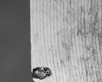


8 (a) (b) (c) (d) (e) (f) Figure 2-2. Examples of discontinuities in welds from preliminary trials at the SKB Canister Laboratory. 10

9 In addition to the surface-breaking and near-surface discontinuities shown in Figure 2-2, there are pores found along the entire length of the weld. Figure 2-3 shows the results from X-ray radiography of a test weld from the Canister Laboratory. Whilst those discontinuities deep into the weld may be said to affect the overall weld quality, they pose no problem from the point-of-view of the lifetime of the canister. Because of the lack of oxidant in the repository, the maximum wall penetration due to corrosion is estimated to be < 2 mm, even for the most conservative of assumptions /King et al, 2001/. Therefore, the porosity at the weld root (location 1 in Figure 2-3) would not impact the service life of the canister. On the other hand, the discontinuities at locations 2 and 3 might be significant, depending upon how close they are to the surface following machining of the fronting bar and canister wall and if they can serve as initiation points for localised corrosion. Figure 2-3. Location of discontinuities along the length of the weld as determined by X-ray radiography. 11
10 3 Mechanisms of localised corrosion and SCC of copper 3.1 Localised corrosion Localised corrosion, i.e. the preferential dissolution of the surface in a discrete localised region, can be broadly divided into two stages: initiation and propagation. The literature relevant to the localised corrosion of copper canisters has been reviewed elsewhere /King et al, 2001/. Here, evidence is presented to address the questions: Can the presence of surface defects increase the probability of the initiation of localised corrosion? Does the presence of surface defects increase the rate, or prolong the duration, of localised penetration? In order to answer these questions, it is useful to consider the mechanism of the pitting of copper in terms of pit initiation, growth, and pit depth. By understanding the factors that contribute to each of these stages of localised corrosion it should be possible to answer the questions of whether pre-existing discontinuities pre-dispose the canister surface to the initiation and/or propagation of pits Initiation Various mechanisms have been proposed for the initiation of pitting of copper, but all share the same basic requirements. Pitting, either in fresh potable water or in more-concentrated chloride solutions such as those to which the canister may be exposed, requires (i) the presence of a passive Cu 2 O and/or Cu(OH) 2 film, (ii) Cl ions, and (iii) a surface potential more positive than a critical potential for pit initiation (usually referred to as the pitting or breakdown potential (E B ) /King et al, 2001/). Figure 3-1 shows a comparison between the corrosion potential (E CORR ) and E B as a function of ph in 0.5 mol dm 3 Cl solution /King, 2002/. Also shown on the figure are the equilibrium lines for the formation of Cu 2 O and Cu 2 O/Cu(OH) 2 predicted from thermodynamic data. There is a clear association between the initiation of pitting and the presence of a surface film, although the data in Figure 3-1 suggest the film in question may be a Cu 2 O/Cu(OH) 2 rather than Cu 2 O. The variation of E B with [Cl ], temperature, and the presence of bicarbonate ions has been discussed elsewhere /King, 2002; King et al, 2001/. The available evidence indicates that pits tend to initiate at grain boundaries or at triple points /Al-Kharafi et al, 1989; de Chialvo et al, 1985; Shalaby et al, 1989/. These locations represent sites at which the protective Cu 2 O film is most likely to break down, because the film will tend to be thicker, more porous and more defected /Al-Kharafi et al, 1989/. Others suggest that pit initiation occurs randomly over the surface and, as support, present evidence that the surface pit distribution follows a Poisson distribution (Figure 3-2) /Laz et al, 1992/. The difference between these two studies probably lies in the different definitions of an initiated pit. /Laz et al, 1992/ observed small (~ 4 µm diameter) crystallographic etch pits, whereas /Al-Kharafi et al, 1989/ were more concerned with initiation events that led to fully propagating pits. Regardless, it is apparent that pit initiation occurs at the microscopic level on a scale of the order of the size of a single grain or smaller. 13
11 ECORR and EB (mvsce) Cu2O/Cu(OH)2 Cu/Cu2O Ecorr Pitting potential ph Figure 3-1. Dependence of the breakdown potential for pitting (E B ) and the corrosion potential (E CORR ) on ph in 0.5 mol dm 3 chloride solution /King, 2002/. 0.3 Probability Number of pits Figure 3-2. Probability of finding a given number of pits within a radius of approximately 10 µm of another pit /Laz et al, 1992/. 14
12 Figures 3-3 to 3-5 show three mechanisms for the initiation (and propagation) of pits on copper. All three mechanisms assume pit initiation occurs at grain boundaries, due either to the rupture of the film at this location or to the preferential dissolution as CuCl 2 through the passive film. In Lucey s mechanism (Figure 3-3), a CuCl pocket is formed under a Cu 2 O layer following Cl diffusion through the film or the hydrolysis of CuCl 2 dissolving locally at the grain boundary. Continued dissolution of this pocket through the Cu 2 O film eventually leads to the familiar cap-covered pit characteristic of Lucey s mechanism (see below). /de Chialvo et al, 1985/ propose that the CuCl pocket is formed under a duplex Cu 2 O/CuO or Cu 2 O/Cu(OH) 2 film, which seems more consistent with the observed correlation between the breakdown potential and the equilibrium potential for this latter process (Figure 3-1). /King and Kolar s, 2000/ mechanism was developed more to address Figure 3-3. Mechanism for the initiation of Type I pitting of copper due to the formation of a CuCl pocket, after /Lucey, 1967/. 15
13 Figure 3-4. Initiation and propagation mechanisms proposed by /de Chialvo et al, 1985/ for the pitting of copper in chloride solutions. the propagation of localised corrosion than its initiation, but also includes initiation at grain boundaries via localised dissolution or film breakdown at these locations. The significant feature of all these initiation mechanisms is that the process occurs on a microscopic scale. Localised defects in the passive film and the presence of Cl are sufficient to drive the formation of a pit. Macroscopic defects, such as those that might remain after the final closure weld, are not required to initiate localised corrosion of the canister. 16
14 Figure 3-5. Proposed mechanism for the under-deposit corrosion of copper canisters under conditions simulating those in a deep geologic repository /King and Kolar, 2000/ Propagation There are a number of pre-requisites for pit propagation on copper surfaces, namely: 1. a supply of oxidant (generally, either O 2 or cupric ions Cu(II)), 2. sustained separation of the anodic and cathodic reactions by a precipitated cap of corrosion products, and 3. a small anode:cathode surface area ratio (although anodic and cathodic surface areas are of similar size in the Lucey mechanism). If all of these factors are not present, then the pit will inevitably stifle and die. Various mechanisms have been proposed for the propagation of pits on copper /King et al, 2001/, a number of which are reviewed here. The most famous mechanism is that proposed by /Lucey, 1967/ to explain the Type I pitting of copper water pipes in potable water. Figure 3-6 shows a cross-section through a pit and illustrates the reactions inherent in Lucey s mechanism. Anodic dissolution of copper in the base of the pit is supported by the cathodic reduction of Cu(II) in the upper half of the pit. The two electrochemical processes are separated by a porous, electrically conducting Cu 2 O membrane. To maintain pit growth, 17
15 Figure 3-6. Cross-section through a Type I pit on copper illustrating the electrochemical, chemical, and mass-transport processes involved in pit propagation /Lucey, 1967/. a continuous supply of O 2 is required to generate Cu(II) in the upper half of the membrane cell.the anode is only maintained as long as the cap of corrosion products is present, thus preventing the diffusive and advective loss of oxidant from the occluded region. The unusual co-location of both anodic and cathodic reactions with approximately equal surface area within the occluded region accounts for the hemi-spherical shape commonly observed for this type of pitting. Others have suggested that the cathode is more conventionally located on the exposed copper surface outside of the occluded region under the cap of corrosion products /Campbell, 1974/. Under chemical conditions associated with Type I pitting, /Sosa et al, 1999/ have determined that as much as 90% of the total cathodic charge is associated with processes occurring outside the pit, raising the possibility of lower aspect ratio (i.e. half-width/depth) pits. In the mechanism proposed by /de Chialvo et al, 1985/ for the pitting of copper in chloride solutions (Figure 3-4), pit propagation occurs via the dissolution of copper as Cu(II) species. This requires that the potential is sufficiently positive (E > E B ) that Cu(II) is formed directly by dissolution, and not as a by-product of the homogeneous oxidation of Cu(I) by O 2. Given that Cu(I) is stabilised in Cl solutions via complex ion formation (i.e. as CuCl 2, CuCl 3 2, etc. species), the potential must exceed a value of ~ 0 V SCE /King and Kolar, 2000/. Such a potential can only be achieved in the presence of O 2 and/or Cu(II). The mechanism proposed by /King and Kolar, 2000/ was developed to explain the underdeposit corrosion observed on copper surfaces exposed to compacted bentonite saturated with a saline ground water solution. Following removal of the precipitated corrosion products, the underlying copper surface was found to be roughened (Figure 3-7). Although the surface is roughened, the entire surface has been corroded (note the position of the original surface of the coupon noted on the figure), suggesting the non-permanent separation of anodic and cathodic sites. The surface was covered by the same corrosion products (CaCO 3, CuCl 2 3Cu(OH) 2 ) as observed for the pitting of copper in chloride environments. /King and Kolar, 2000/ proposed a mechanism to explain these observations that accounted for both pit propagation and death (Figure 3-5). Propagation is characterised by an anodic:cathodic surface area ratio < 1 and pit death by a value > 1. Propagation was 18
16 Figure 3-7. Surface profile of copper specimen exposed to compacted bentonite:sand buffer material saturated with aerated saline ground water at 50 C for 733 days /King and Kolar, 2000/. considered to occur in an occluded region formed by the precipitation of CaCO 3 and/or CuCl 2 3Cu(OH) 2 (Figure 3-5d). Continued propagation is contingent on the maintenance of the occluded region and a supply of oxidant (O 2 or, possibly, Cu(II)). Three processes were considered that could lead to pit death: (i) blockage of cathodic sites by the precipitation of CaCO 3, (ii) opening of the cap of corrosion products, allowing diffusive mixing of the occluded and bulk environments, and (iii) coalescence of pits, thus increasing the anodic:cathodic surface area ratio (Figures 3-5e to g, respectively). The respective locations of the anodic (A) and cathodic (C) processes are illustrated in the upper pane of each figure. The factors that might lead to pit death by each of these routes were not discussed by /King and Kolar, 2000/, but the increasing radius of a propagating pit would tend to lead to pit death by either the pit-opening or pit-coalescence routes. The larger the pit, the more likely the cap of corrosion products is to become defected by internal stresses. In addition, larger pits are more likely to coalesce with other neighbouring pits. If increasing pit diameter promotes death by the pit-opening or pit-coalescence mechanisms, then an estimate of the maximum pit diameter can be obtained from the profile in Figure 3-7. The profile exhibits approximately 37 peaks, representing 36 pits with a mean diameter of 0.28 mm. Another estimate of the maximum pit diameter can be obtained from the data of /Mankowski et al, 1997/, who characterised pits formed on copper in chloride and sulphate environments. Figure 3-8 shows a series of coalesced pits formed on copper in 0.1 mol dm 3 Cl solution. The average diameter of the individual pits is of the order of a few tenths of a mm, the same as that inferred from Figure 3-7. There is evidence, therefore, for a maximum pit diameter on copper exposed to Cl solutions. Pits with a diameter greater than a few tenths of a mm tend to coalesce and will inevitably die as the suddenly increased anodic:cathodic surface area ratio is insufficient to sustain the acidified anodic electrolyte inside the occluded cell. Pit opening would also lead 19

17 Figure 3-8. Photograph of overlapping pits on copper exposed to 0.1 mol dm 3 chloride solution /Mankowski et al, 1997/. to an increase in anodic:cathodic surface area ratio and pit death. However, although fracturing of the corrosion product is more likely to occur as the pit diameter increases, there is no direct experimental evidence that this mechanism contributes to the nonpermanent separation of anodic and cathodic sites evident from the profile in Figure 3-7. Additional experimental evidence that there is a maximum diameter for the formation of a stable occluded pit comes from the results of a limited series of tests reported by /Ryan et al, 1994/. Various types of copper coupon were exposed to a synthetic ground water/bentonite slurry at a temperature of 100 C in the presence of a γ-radiation field (absorbed dose rate 4.5 Gy/hr), with a maximum exposure period of 4.0 yr. The ground water was initially aerated and had a Cl concentration of 0.97 mol dm 3. Among these samples were two so-called artificially pitted coupons (Figure 3-9). The samples (approximately 2.5 cm long x 1.25 cm wide x 0.63 cm deep) contained two rows of drilled holes (~ 0.5 mm diameter x 2-4 mm deep) to simulate pre-existing pits. The aim of the test was to determine whether these pits would propagate under simulated repository conditions. Figure 3-9. Schematic of the artificially pitted copper sample exposed to simulated repository conditions by /Ryan et al, 1994/. For clarity, only a single row of pits is shown. See text for details regarding the sample and exposure conditions. 20
18 At the end of the exposure period, the samples were examined for evidence of preferential localised corrosion in and surrounding the artificial pits. No such localised attack was observed, the drilled holes retaining the sharp edges of the original machining. No cap of corrosion products or precipitated CaCO 3 formed over the pits, which instead became filled with clay particles from the ground water/bentonite slurry used in the tests. Another experimental technique used to determine the propensity for pit propagation is the measurement of the re-passivation potential (E RP ) of propagating pits (Figure 3-10). Pits are generally initiated electrochemically by scanning the potential in the positive (anodic) direction until the potential exceeds E B. Reversing the direction of the potential scan typically results in higher currents during the reverse scan due to propagation of the newly initiated pits. Eventually, however, the pits re-passivate as the potential is scanned to morenegative potentials and the driving force for dissolution diminishes. In effect, such tests represent the initiation, propagation, and pit death processes considered by /King and Kolar, 2000/ (Figure 3-5). Table 3-1 shows data for the breakdown, re-passivation and corrosion potentials of oxygenfree copper in various synthetic ground water solutions /Sridhar and Cragnolino, 1993/. Relatively few instances of pitting were reported by these authors and in many cases the values of E RP and E B are identical. The results in Table 3-1 support the concept that propagating pits on copper re-passivate relatively easily. The limited data presented by /Sridhar and Cragnolino, 1993/ on the nature of the pitting that was observed suggests that, although initiation as micro-pits occurs readily, the maximum pit diameter is of the order of 0.1 mm. The largest pits appeared to be formed by the coalescence of smaller pits, as illustrated in Figure 3-5 g. The re-passivation of growing pits in the laboratory by scanning the potential to more-cathodic potentials is analogous to re-passivation of pits on a copper canister due to a decrease in the amount of available oxidant. The function of both the potentiostat in the laboratory and the oxidant in a naturally corroding system is to sustain copper dissolution in the occluded cell at a sufficient rate to prevent re-passivation. In summary, the continued propagation of pits requires (i) a sufficient source of oxidant (O 2 or Cu(II)), (ii) a persistent occluded geometry created by a cap of corrosion products, and (iii) a small anodic:cathodic surface area ratio (for the formation of low aspect ratio pits). In E RP E B E CORR Positive potential direction Figure Schematic illustrating the measurement of the breakdown (E B ) and re-passivation (E RP ) potentials for localised corrosion of a passive material in cyclic polarisation experiments. The corrosion potential (E CORR ) is shown schematically and is best determined in separate experiments in which the sample is not polarised. 21
19 Table 3-1. Comparison of corrosion, breakdown, and re-passivation potentials in various environments /Sridhar and Cragnolino, 1993/. The tests in which pits were visually seen on the coupon surface are highlighted in bold font [Cl ] (µg/g) [HCO 3 ] (µg/g) [SO 2 4 ] (µg/g) Temp. ( C) E CORR (mv SCE) E B (mv SCE) E RP (mv SCE) (E B E RP) (mv) the absence of these factors, pits on copper tend to die (or re-passivate). Factors that lead to pit death include: (a) blockage of the cathode surface by the precipitation of CaCO 3 or other non-conducting corrosion products, (b) the opening of the occluded cell by fracture of the cap of corrosion products, allowing mixing of the pit and bulk solutions, and (c) coalescence of adjacent pits. Each of these factors results in an increase in the anodic:cathodic surface area ratio. There is evidence for a maximum diameter of isolated pits on copper of mm. Above this diameter, pits will tend to coalesce and the surface become roughened as opposed to pitted. 3.2 Stress corrosion cracking Initiation Stress corrosion cracking (SCC) is the result of the conjoint action of a tensile stress on a susceptible material in an aggressive environment. Therefore, it is useful to consider aspects of both the initiation and propagation of SCC in terms of material, mechanical, and environmental factors. Relatively little information is available regarding the effects of material properties of pure copper on the initiation of SCC /King et al, 2001/. Of those studies that have been performed, the only ones relevant to the initiation of SCC as a result of surface discontinuities or changes in material properties due to welding involve the effect of grain size. Cracks inevitably initiate intergranularly at grain boundaries, even in environments in which crack growth is transgranular. Thus, larger grained material, as might result from grain growth during welding, exhibits a lower density of initiated cracks /Pugh et al, 1969; Yu et al, 1987/. Surface discontinuities could promote SCC initiation through their effect as stress intensifiers. Discontinuities exhibiting sharp crack-like features, such as that shown in Figure 2-2f, affect the stress intensity factor (K I ) at the crack tip. For blunt discontinuities or pits, such as those shown in Figure 2-2c and e, the appropriate measure is the stress concentration factor /Pilkey, 1997/. The effect of crack-like and blunt discontinuities can then be determined by comparison with threshold stress intensity factors or threshold stresses for crack initiation. 22
20 Various authors have tried to determine the threshold stress intensity factor for SCC (K ISCC ) in OF-Cu /King et al, 2001/. Figure 3-11 shows data from /Pettersson and Oskarsson, 2000/ for OF-Cu in sodium nitrite solution that suggests a K ISCC value of ~ 30 MPa m 1/2. In order to observe any crack growth, these authors found it necessary to introduce cold work to strengthen the material, the opposite of the material softening likely to result from the final closure weld. For annealed OF-Cu, /King et al, 1999/ suggested a threshold stress intensity factor of ~ 22 MPa m 1/2. However, reviewing the data from these studies and that of /Hietanen et al, 1996/, /Rosborg and Werme, 2001/ noted that the variability in reported K ISCC values (from 16 to 30 MPa m 1/2 ) makes it difficult to define a single value for life prediction purposes. There are a number of measurements of the threshold stress for the initiation (and growth) of SCC cracks reported in the literature /King et al, 2001/. /Saario et al, 1999/ reported a threshold stress of 120 MPa for copper in sodium nitrite solution. /Sato and Nagata, 1978/ found that the threshold stress in ammonia environments was a function of the phosphorus content of the material. Below a P content of ~ 80 ppm, the threshold stress was > 200 MPa, but diminished considerably for P contents of between 80 and 250 ppm to a value of ~ 40 MPa. The P content of the OF-Cu to be used to fabricate canisters is likely to be of the order of ~ 50 ppm /Werme, 1998/, so that the threshold stress for SCC for a canister will be 120 MPa. Another impact of the applied stress is the accompanying strain. As noted by /Parkins, 1985/, the strain that results from the applied stress is likely to be equally or more important for crack initiation and growth than the stress itself. Strain, especially local plastic deformation, is responsible for the rupture of protective oxide films at grain boundaries or at the crack tip. Figure Effect of stress intensity factor on the crack growth rate for OF-Cu in sodium nitrite solution /Pettersson and Oskarsson, 2000/. 23
21 /Sieradzki and Kim, 1992/ observed a dynamic interaction between the strain rate and the rate of dissolution of Cu in ammonia solutions. These authors were able to initiate transgranular SCC of copper in ammonia solutions via a film-induced cleavage mechanism for certain combinations of the rate of dissolution and the strain rate. Under these conditions, a micro-pitted surface layer was produced, the fracture of which was able to sustain crack propagation into the underlying ductile base material. However, the scale of the porosity and the properties of this surface film are crucial in determining whether SCC will occur /Sieradzki and Newman, 1985/, and the macro-porosity resulting from welding discontinuities would not support crack initiation via this mechanism. Environmental factors are clearly important in the initiation (and growth) of cracks, since SCC has only been observed on OF-Cu in the presence of certain specific species and over well-defined ranges of electrochemical potential /King et al, 2001/. These environments (nitrite, ammonia, and acetate) exhibit the required combination of film-formation and dissolution necessary for crack initiation. Perhaps the most important property of the environment with respect to crack initiation, is the formation of a protective film. Cracking is only observed in these solutions at combinations of potential and ph at which a Cu 2 O (or Cu 2 O/Cu(OH) 2 ) film is stable /Benjamin et al, 1988; Cassagne et al, 1990; Suzuki and Hisamatsu, 1981/. In addition to considering the separate effects of material, mechanical, and environmental factors, it is worth considering the effects of pits, which have a special relationship to the initiation of SCC. Much of the evidence linking pitting to crack initiation comes from studies on materials other than copper alloys, in particular the numerous studies of the SCC of C-steels. However, the possibility that a similar link may also exist for OF-Cu is illustrated by the data in Figure This figure shows a comparison of the pitting (or breakdown) potential E B measured in acetate solution in the absence of Cl ions /Laz et al, 1992/ and threshold potentials for SCC measured on smooth tensile samples using slow strain rate testing in acetate and nitrite solution. (These threshold potentials are simply potentials below which SCC was not observed on laboratory timescales, and may or may not represent a true mechanistic threshold for SCC). Slow strain rate testing on smooth samples involves both the initiation and propagation of cracks, although opinions differ of the relative importance of each process in the overall test. There appears to be a close correlation between E B and E SCC, although whether this is because cracks are initiated from pits or whether both processes involve the breakdown of a Cu 2 O/Cu(OH) 2 surface film is uncertain. Two distinct mechanisms have been proposed to explain the role of pits in crack initiation /Parkins, 1985/. Pits, along with other notch-like features, act as stress raisers /Pilkey, 1997/ and may concentrate the applied stress so that it exceeds a critical threshold stress for crack initiation. Strong evidence linking the stress intensification by pits to the initiation of SCC on C-steel has been presented by /Christman, 1990/, amongst others. A second, less obvious, effect of pits is to alter the composition of the environment and the potential of the surface in localised occluded regions. /Parkins, 1985/ has suggested that this latter effect is more important than the stress intensification effect under some circumstances. As discussed in Section 3.1.2, however, there may be an upper limit to the dimension at which a pit can still affect the local environment. In summary, like pit initiation, the initiation of SCC cracks occurs at a microscopic level, generally at grain boundaries or other sub-grain size features, such as slip steps. The presence of a surface film (most likely possessing a duplex Cu 2 O/Cu(OH) 2 structure) appears an important pre-requisite for cracking. 24
22 200 ESCC and EB (mvsce) Cu2O/Cu(OH)2 Cu2O/CuO Cu/Cu2O Pitting potential SCC Potential ph (a) Pitting and cracking potentials in acetate solutions ESCC and EB (mvsce) Cu2O/Cu(OH)2 Cu2O/CuO Cu/Cu2O Pitting potential ph (b) Pitting potentials in acetate and cracking potentials in nitrite solutions. E SCC determined by 1: /Uchida et al, 1991/, 2: /Yu and Parkins, 1987/, 3: /Benjamin et al, 1988/, 4: /Cassagne et al, 1990/. Figure Comparison of pitting (breakdown) potentials measured in acetate solutions and potentials for SCC on smooth tensile samples determined in acetate and nitrite solutions. 25
23 3.2.2 Propagation Many of the same factors that are important for crack initiation are also important for crack propagation. To some extent this conclusion arises from the difficulty of distinguishing crack initiation from crack propagation. Crack growth requires a specific environment acting on a susceptible material under a tensile stress. The various mechanisms used to describe crack propagation on copper have been described in more detail elsewhere /King et al, 2001/. Here, only two aspects of crack growth will be considered; crack chemistry and the effects of strain and strain rate on crack growth. For many SCC systems, a significant difference in chemistry develops between the environment inside the crack and that in the bulk. Differences in chemistry can arise from the acidification of the crack solution by the hydrolysis of dissolved metal ions, in much the same way that acidic pit and crevice chemistries develop in localised corrosion. Potential gradients along the crack can result in significant differences in potential between the crack tip and the crack mouth. Both hydrolysis and the potential gradient will cause an increase in the concentrations of anions (most likely chloride or sulphate) inside the crack. These differences might be enhanced, or sustained, by pre-existing surface discontinuities. Of the various mechanisms proposed for crack growth of OF-Cu, the most generally accepted (the film rupture/anodic dissolution and tarnish-rupture mechanisms) involve preferential dissolution at the crack tip /King et al, 2001/. To sustain growth, the crack chemistry must support not only dissolution at the crack tip but also passivation of the crack walls, so that the crack remains sharp and does not become blunted. For such mechanisms, however, there is little driving force for the development of potential and concentration gradients along the crack. As stated above, the crack walls must be passive to avoid blunting, so the current flowing along the crack is necessarily small. Thus, the transport of anions into the crack by electro-migration is also minimal. Copper will dissolve as cuprous species, which do not hydrolyse strongly, especially in the presence of chloride ions. Therefore, local acidification will also be minimised. The crack environment, therefore, will be similar to the bulk environment, so that even if surface discontinuities were to exacerbate any differences in the conditions inside the crack, these differences are likely to be small for OF-Cu. A second effect that surface discontinuities might have on the propagation of cracks in OF-Cu is the enhancement of stress at the crack tip. For dissolution-based mechanisms involving rupture of a surface film, however, the resultant strain is more important than the stress itself. For crack propagation, it is generally found that the rate of change of strain is the more-important parameter /Parkins 1985, 1988/, since crack advance is a balance between the rate of dissolution and the rate of rupture of the film. Strain may result from creep of the material. Although creep could rupture protective films resulting in crack growth (or initiation), it could also blunt cracks by relieving the stress at the crack tip. Stress relief through creep is more likely at higher temperatures. There is evidence from the work of /Pettersson and Oskarsson, 2000/ that crack-tip creep slows crack growth since, under constant load conditions, the crack growth rate decreased with time. Creep exhaustion is commonly postulated as the cause of crack dormancy in C-steels /Parkins, 2000/. Thus, enhancement of the crack-tip strain or strain rate by surface discontinuities may lead to crack dormancy because of the stress relief promoted by creep. 26
24 3.3 The effect of surface finish Although not directly related to the effect of surface discontinuities on localised corrosion and SCC, the effect of the surface finish on these processes is also of interest. The current specification for the surface finish on canisters is DIN ISO 1302 N9, which corresponds to a surface texture of 6.3 µm (the mean distance between the median surface height and the various peaks and troughs). /Raicheva, 1984/ studied the effect of surface preparation on the electrochemical behaviour of pure copper in acidic O 2 -containing KCl solution. Surfaces were prepared by either sequential mechanical polishing to final grit sizes varying from 42 µm to 210 µm or by chemical or electrochemical polishing techniques. The only effect of the mechanical polishing (which, of those studied, most-closely corresponds to the type of surface preparation for the canister) was on the effective surface area for the anodic and cathodic reactions. By correcting for the differences in surface area for the different grit sizes, /Raicheva, 1984/ was able to show that other effects, such as the local surface plastic deformation introduced by polishing, had no effect on the rate of hydrogen evolution in acidified 1 mol dm 3 KCl solution. Although no dissolution data were presented, it was implied that the difference in effective surface area was also the only effect of polishing on the anodic kinetics. This latter point is important, since it allows the effect of surface finish on the corrosion potential E CORR to be predicted. If the effective surface areas for the anodic and cathodic reactions are equally affected by mechanical polishing, then E CORR will not be a function of the surface roughness. This is important, since it means that local galvanic cells will not be established on different parts of the surface that exhibit different degrees of surface roughness. Therefore, the surface finish will not affect the probability of the initiation of localised corrosion or SCC. 27
25 4 Discussion of the effects of discontinuities on the corrosion behaviour of copper canisters 4.1 General considerations Discontinuities of relevance to corrosion behaviour of canister Not all discontinuities will be important for the corrosion behaviour of the canister. Those discontinuities located deep within the canister shell will not impact corrosion processes at any stage during the canister service life. Of most importance are surface-breaking defects. Because of the limited amount of oxidant in the repository, sub-surface discontinuities will be less important. Based on a maximum wall penetration by general and localised corrosion of 2 mm /King et al, 2001/, it can be assumed that sub-surface defects located deeper than 2 mm from the canister surface will never be exposed to the repository environment and will, therefore, not influence the corrosion behaviour of the canister Importance of microscopic and macroscopic surface features It is apparent from the discussion above that the initiation of localised corrosion and stress corrosion cracking occurs on a much smaller physical scale than that represented by weld discontinuities. Pit initiation is a microscopic process, occurring due to the localised breakdown of a protective surface film at grain boundaries (Figures 3-3, 3-4, and 3-5). Similarly, the initiation of SCC invariably occurs at grain boundaries, even in environments that support transgranular crack growth /Pugh et al, 1969; Yu et al, 1987/. Weld discontinuities of the kind illustrated in Figure 2-2, on the other hand, represent a macroscopic scale of defect. Therefore, from the viewpoint of the initiation of localised corrosion and SCC by the breakdown of a protective surface film, the presence of such discontinuities should have no detrimental effect whatsoever Effect of evolving redox conditions within the repository The environmental conditions within the repository will evolve over time from initially warm and oxidising to ultimately cool and anoxic /King et al, 2001/. Both localised corrosion and SCC are generally associated with oxidising environments. It is reasonable to assume, therefore, that any impact of discontinuities on the corrosion behaviour of the canister will only be felt during this initial oxidising period. The importance of the evolution of the repository environment can be illustrated by considering the processes determining the propagation (and death) of pits. The requirements for pit growth include: 1. Permanent separation of anodic and cathodic sites. 2. Anodic current density in the occluded region must be greater than that on the exposed surface. Under oxidising conditions, these two criteria are generally met through the creation of an occluded region capped by a layer of precipitated corrosion products (see, for example, Figures 3-3 to 3-6). Pit growth will continue as long as the flux of O 2 to the external surface 29
26 is maintained (provided the pit does not grow too wide that the cap of precipitated corrosion products cannot be sustained in which case the pit will die, Figure 3-5 f). Under anoxic conditions, however, it will be difficult to sustain the anodic reaction in the occluded region. In the presence of sulphide (HS ) the anodic reaction is /King et al, 2001/ 2Cu + HS Cu 2 S + H + + 2e (4-1) There is evidence that the rate of the anodic reaction is limited by the rate of supply of HS to the copper surface /King et al, 2001/; (D W Shoesmith, private communication 2003). It is physically impossible to sustain a localised process in an occluded region if the anodic reaction is mass-transport controlled by the supply of a reactant from the bulk environment. Under these circumstances, the rate of supply of HS to the pit would be significantly smaller than to the exposed surface, so that the second criterion for pit growth listed above cannot be maintained. Therefore, the effects of localised corrosion, and any impact that pre-existing discontinuities may have, is an issue only during the initial oxidising phase of the evolution of the repository environment. 4.2 Localised corrosion Initiation and propagation As noted above, pit initiation results from the breakdown of a protective surface film at grain boundaries. The breakdown process can be determined electrochemically through the measurement of the breakdown or pitting potential E B. In naturally corroding systems, the surface will pit if the corrosion potential E CORR becomes more anodic than E B. There is no evidence that the presence of pre-existing surface discontinuities affects either E CORR or E B. In general, the types of discontinuity illustrated in Figure 2-2 are too large to influence an event (i.e. pit initiation) that occurs on the microscopic level. Similarly, an argument can be made that many of these discontinuities are too large to sustain pit growth. Evidence has been presented in Section that individual pits exhibit a maximum diameter of mm, and that above this size the individual pits coalesce. Pit coalescence leads to the death of a propagating pit because of the associated increase in the anodic:cathodic surface area ratio (Figure 3-5g). In the repository, this effect will be compounded by the decrease in O 2 flux to the canister surface as the repository environment evolves over time. Thus, the types of discontinuity shown in Figure 2-2 are too physically too large to cause pit initiation or sustained growth Growth of hemispherical discontinuities Despite the conclusion above that surface discontinuities are too large to lead to sustained pit growth, it is illustrative to consider the maximum possible pit diameter on a canister if sustained growth were possible. Consider a hemispherical surface-breaking discontinuity of initial radius r 1 (Figure 4-1). Let us assume that as the discontinuity grows the hemispherical shape is maintained. Dissolution is supported by the cathodic reduction of O 2 on the external surface surrounding the pit. The width of the circular annulus on which the cathodic reaction occurs is r 2, and is determined by the extent to which the anodic and 30
27 r 2 O 2 2r 1 r 2 O 2 Figure 4-1. Illustration of an idealised hemispherical surface-breaking discontinuity. cathodic reactions can galvanically couple on the surface of a canister embedded in compacted bentonite. The flux of O 2 to the canister wall is time dependent. The predicted time dependence of the O 2 flux and of the cumulative amount of diffused O 2 (Q O2 ) is shown in Figure 4-2. These predictions are based on the assumption that the O 2 reduction reaction is transport limited and that all of the O 2 initially in the borehole (both dissolved O 2 and gaseous O 2 in the initially unsaturated pores, initial degree of saturation 60%, porosity 0.41) diffuses through the pore water (assumed diffusion coefficient 1 x 10 7 cm 2 s 1 ). Based on these calculations, ~ 99% of the O 2 is consumed within the first ~ 3000 years, which can be used as a definition of the length of the aerobic phase. 1.2E E-12 Amount of O2 diffused (mol cm -2 ) 1.0E E E E E-05 Amount O2 diffused O2 flux 4E E-12 3E E-12 2E E-12 1E-12 5E-13 O2 flux (mol cm -2 s -1 ) 0.0E E-08 1E Time (yr) Figure 4-2. Predicted time dependence of the flux of O 2 to the canister surface and of the time-integrated amount of O 2 that has diffused (see text for details). 31
Used Fuel Container Designs and Lifetime Prediction
 Used Fuel Container Designs and Lifetime Prediction CNS Conference on Waste Management, Decommissioning and Environmental Restoration for Canada s Nuclear Activities Toronto, Canada September 11-14, 2011
Corrosion of copper in final disposal environments. Jari Aromaa Aalto Unversity Hydrometallurgy and Corrosion Research Group
 Corrosion of copper in final disposal environments Jari Aromaa Aalto Unversity Hydrometallurgy and Corrosion Research Group Contents The concept Corrosive environments Copper corrosion mechanisms Copper
Corrosion of disposal canisters
 Corrosion of disposal canisters Fraser King Integrity Corrosion Consulting Ltd, Canada Consultant to Nagra Outline Forms of corrosion - Types of corrosion - Control by design Nature of the disposal environment
Active/Passive Conditions on Copper Containers under Nuclear Waste Repository Environment
 6 th International Workshop on Long-term Prediction of Corrosion Damage in Nuclear Waste Systems, Toronto, Canada, May 9-12, 2016 Active/Passive Conditions on Copper Containers under Nuclear Waste Repository
Influence of high chloride concentration on copper corrosion
 Public Memo publication Document ID 1398014 Author Version 1.0 Christina Lilja Reviewed by Saida Engström Olle Olsson Allan Hedin Approved by Anders Ström Status Approved Reg no Date 2013-06-04 Reviewed
Inspection of Friction Stir Welds using Triple Array Methods
 More Info at Open Access Database www.ndt.net/?id=16618 Inspection of Friction Stir Welds using Triple Array Methods Barend van den Bos 1, Sara Axelsson 1, Ulf Ronneteg 2, Thomas Grybäck 2 1 Exova Materials
Effect of Hydrogen Absorption on SCC of Copper in Deoxygenated Sulfide and Chloride Containing Water
 Effect of Hydrogen Absorption on SCC of Copper in Deoxygenated Sulfide and Chloride Containing Water Hannu Hänninen, Antti Forsström, Yuriy Yagodzinskyy Aalto University School of Engineering KYT2018 2
At the end of this lecture you should be able to
 LECTURE 5 FRACTURE AND OXIDATION OBJECTIVES At the end of this lecture you should be able to 1. Define fracture, and distinguish between different types of fracture 2. Describe measures that can be used
TR Technical Report. Corrosion resistance of copper canister weld material. Rolf Gubner, Urban Andersson Corrosion & Metals Research Institute
 Technical Report TR-07-07 Corrosion resistance of copper canister weld material Rolf Gubner, Urban Andersson Corrosion & Metals Research Institute March 2007 Svensk Kärnbränslehantering AB Swedish Nuclear
Intergranular Corrosion (IGC)
") Intergranular Corrosion (IGC) Microstructure of metals and alloys is made up of grains (separated by grain boundaries) Intergranular corrosion is a localized attack along the grain boundaries, or immediately
Intergranular Corrosion (IGC) Microstructure of metals and alloys is made up of grains (separated by grain boundaries) Intergranular corrosion is a localized attack along the grain boundaries, or immediately
Mechanical Integrity of Copper Canister Lid and Cylinder
 SKI Report 2003:05 Research Mechanical Integrity of Copper Canister Lid and Cylinder Marianne Karlsson January 2002 ISSN 1104 1374 ISRN SKI-R-03/05-SE SKI perspective Background and purpose of the project
R Stress application and the effect on creep of copper. Karin Mannesson, Henrik C M Andersson-Östling Swerea KIMAB AB.
 R-14-31 Stress application and the effect on creep of copper Karin Mannesson, Henrik C M Andersson-Östling Swerea KIMAB AB May 2016 Svensk Kärnbränslehantering AB Swedish Nuclear Fuel and Waste Management
Corrosion Simulation. OLI Simulation Conference A. Anderko, G. Engelhardt and M.M. Lencka
 OLI Simulation Conference 2010 Corrosion Simulation Think Simulation! Harnessing the power of the OLI Engine A. Anderko, G. Engelhardt and M.M. Lencka General and localized corrosion models Single-phase
EFFECTS OF MECHANICALLY DRILLED PITS ON TENSILE DUCTILITY AND FRACTURE BEHAVIOR OF A STRUCTURAL STEEL
 EFFECTS OF MECHANICALLY DRILLED PITS ON TENSILE DUCTILITY AND FRACTURE BEHAVIOR OF A STRUCTURAL STEEL Somayeh ALIPOUR, Hassan FARHANGI and Changiz DEHGHANIAN School of Metallurgy and Materials Engineering,
1. Project special reports
 1. Project special reports 1.1 Deformation localisation and EAC in inhomogeneous microstructures of austenitic stainless steels Ulla Ehrnstén 1, Wade Karlsen 1, Janne Pakarinen 1, Tapio Saukkonen 2 Hänninen
Laboratory Experiments in Corrosion Engineering II
 Lecture - 40 Laboratory Experiments in Corrosion Engineering II Keywords: Polarization Experiments, Pitting Potentials, Microbial Corrosion. A. Electrochemical tests in a given environment Polarization
R Metallographic Analysis of SKB MiniCan Experiment 3. Nicholas Smart, Simon Rose, David Nixon, Andrew Rance AMEC.
 R-13-35 Metallographic Analysis of SKB MiniCan Experiment 3 Nicholas Smart, Simon Rose, David Nixon, Andrew Rance AMEC November 2013 Svensk Kärnbränslehantering AB Swedish Nuclear Fuel and Waste Management
Materials of Engineering ENGR 151 CORROSION ELECTRICAL PROPERTIES
 Materials of Engineering ENGR 151 CORROSION ELECTRICAL PROPERTIES more anodic (active) more cathodic (inert) GALVANIC SERIES Ranking of the reactivity of metals/alloys in seawater Platinum Gold Graphite
STRESS CORROSION CRACKING OF STAINLESS STEELS IN HIGH PRESSURE ALKALINE ELECTROLYSERS
 STRESS CORROSION CRACKING OF STAINLESS STEELS IN HIGH PRESSURE ALKALINE ELECTROLYSERS Haraldsen, K. 1 and Leth-Olsen, H. 1 1 Corporate Research Centre, Norsk Hydro ASA, P.O.Box 2560, 3908 Porsgrunn, Norway
HURST CORPORATION STAINLESS STEEL
 STAINLESS HURST CORPORATION STEEL PRIMER www www.hurstcorp.com 2007 OVERVIEW Stainless steel is an iron-based metal which contains very low carbon levels (compared to mild steel) and various levels of
Current status of copper corrosion research at SKB
 Current status of copper corrosion research at SKB KYT Copper Corrosion Seminar Christina Lilja 2017-11-02 Overview Status in the Swedish Programme Corrosion issues mentioned by SSM from safety assessment
Safety Information Bulletin Airworthiness SIB No.: R1 Issued: 13 September 2018
 Safety Information Bulletin Airworthiness SIB No.: 2018-04R1 Issued: 13 September 2018 Subject: Environmentally Assisted Cracking in certain Aluminium Alloys EASA SIB No.: 2018-04R1 Revision: This SIB
Corrosion Control and Cathodic Protection Data Sheet
 Data Sheet CORROSION CONTROL Corrosion control is the application of engineering principles and procedures to minimise corrosion to an acceptable level by the most economical method. It is rarely practical
THE ÄSPÖ HARD ROCK LABORATORY
 THE ÄSPÖ HARD ROCK LABORATORY A dress rehearsal for the construction of a final repository for spent nuclear fuel is currently being held deep down in the Swedish bedrock in the Äspö Hard Rock Laboratory
Failure Analysis of Cracked Reducer Flange
 J Fail. Anal. and Preven. (2010) 10:480 485 DOI 10.1007/s11668-010-9389-9 Failure Analysis of Cracked Reducer Flange Khaled Habib Submitted: 18 May 2010/in revised form: 29 July 2010/Published online:
MACROSTRUCTURE, MICROSTRUCTURE AND MICROHARDNESS ANALYSIS
 109 Chapter 5 MACROSTRUCTURE, MICROSTRUCTURE AND MICROHARDNESS ANALYSIS 5.1 INTRODUCTION The microstructural studies of friction welding helps in understanding microstructural changes occurred during friction
Grain Boundary Control for Improved Intergranular Stress Corrosion Cracking Resistance in Austenitic Stainless Steels
 Grain Boundary Control for Improved Intergranular Stress Corrosion Cracking Resistance in Austenitic Stainless Steels J MARROW, D ENGELBERG, A JIVKOV, P WOOD, L. BABOUT, N STEVENS Materials Performance
EFFECT OF COPPER AND COPPER OXIDE ON CORROSION OF BOILER STEEL
 06 koperoxide www.hbscc.nl - 1 - EFFECT OF COPPER AND COPPER OXIDE ON CORROSION OF BOILER STEEL W.M.M. HUIJBREGTS Mitteilungen der V.G.B., Vol. 51, No.3, pp. 229-235, June 1971 ABSTRACT Electrochemical
Chapter Outline: Failure
 Chapter Outline: Failure How do Materials Break? Ductile vs. brittle fracture Principles of fracture mechanics Stress concentration Impact fracture testing Fatigue (cyclic stresses) Cyclic stresses, the
Electronics materials - Stress and its effect on materials
 Electronics materials - Stress and its effect on materials Introduction You will have already seen in Mechanical properties of metals that stress on materials results in strain first elastic strain and
Mat E 272 Lecture 26: Oxidation and Corrosion
 Mat E 272 Lecture 26: Oxidation and Corrosion December 11, 2001 Introduction: Environmental degradation of materials is one of the most costly failure modes, accounting for over 5 percent of the total
Propagation of Localised Corrosion: FEM Approach
 Propagation of Localised Corrosion: FEM Approach M. Stroe *,1, R. Oltra 1, B. Vuillemin 1, G. Girardin 2 1. Institut Carnot de Bourgogne (ICB), 2. AREVA NP *ICB, UMR 5209 CNRS-Université de Bourgogne,9
CH 6: Fatigue Failure Resulting from Variable Loading
 CH 6: Fatigue Failure Resulting from Variable Loading Some machine elements are subjected to statics loads and for such elements, statics failure theories are used to predict failure (yielding or fracture).
TR Technical Report. Stress corrosion cracking of copper canisters. Fraser King, Integrity Corrosion Consulting Limited
 Technical Report TR-10-04 Stress corrosion cracking of copper canisters Fraser King, Integrity Corrosion Consulting Limited Roger Newman, University of Toronto December 2010 Svensk Kärnbränslehantering
Transactions on Engineering Sciences vol 13, 1996 WIT Press, ISSN
 Improvement in corrosion resistance of CrN coating steel with multi-stage deposition method and its corrosion fatigue strength M. Sonobe, K. Shiozawa, K. Motobayashi Department of Mechanical Systems Engineering,
View from the Penthouse
 View from the Penthouse The DNFM Technical News Letter David N. French Metallurgists Ph: 502-955-9847 Fax: 502-957-5441 Web: www.davidnfrench.com Stress-corrosion-cracking (SCC) is a well-defined failure
Fracture. Brittle vs. Ductile Fracture Ductile materials more plastic deformation and energy absorption (toughness) before fracture.
 before fracture.") 1- Fracture Fracture: Separation of a body into pieces due to stress, at temperatures below the melting point. Steps in fracture: 1-Crack formation 2-Crack propagation There are two modes of fracture depending
1- Fracture Fracture: Separation of a body into pieces due to stress, at temperatures below the melting point. Steps in fracture: 1-Crack formation 2-Crack propagation There are two modes of fracture depending
Radiation induced corrosion of copper for spent nuclear fuel
 New insights into the repository s engineered barriers, Stockholm, Nov. 20, 2013 Radiation induced corrosion of copper for spent nuclear fuel g-radiation Water Oxide Copper C. Leygraf, Å. Björkbacka, S.
Candidate Material Solutions for the Design of Nuclear Waste Storage Canisters
 Candidate Material Solutions for the Design of Nuclear Waste Storage Canisters Stuart Holdsworth High Temperature Integrity Mechanical Integrity for Energy Systems Candidate solutions for nuclear waste
PREDICTING THE CORROSION AND STRESS CORROSION
 PREDICTING THE CORROSION AND STRESS CORROSION PERFORMANCE OF COPPER IN ANAEROBIC SULFIDE SOLUTION BY GANESH BHASKARAN (Under Supervision of Prof. ROGER C. NEWMAN) A thesis submitted in conformity with
Study of Electrochemical Polishing Applications in some alloys to obtain high surface finish
 Study of Electrochemical Polishing Applications in some alloys to obtain high surface finish Niveen J. Abdalkadir Lecturer University of Technology/ Materials Engineering Hussain M. yousif Chief of engineer
PERFORMANCE ANALYSIS OF COPPER CANISTER CORROSION UNDER OXIDIZING OR REDUCING CONDITIONS
 695 PERFORMANCE ANALYSIS OF COPPER CANISTER CORROSION UNDER OXIDIZING OR REDUCING CONDITIONS KAREN WORGAN*, MICHAEL APTED* AND ROLF SJOBLOM** * Intera Information Technologies, Inc., Denver, Colorado 80235
Finding the Root Cause is Critical
 Finding the Root Cause is Critical Have you ever repaired a tube leak and put the boiler back in service, only to be forced off-line by another leak? Identifying and correcting the root cause is essential.
ME 415 Failure Analysis and Prevention Failure of the Fortnight #4 H-1 Engine LOX Dome Failure. Evrim ERSU (ee51) Due Date: Thursday, March 29!!
 Due Date: Thursday, March 29!!") ME 415 Failure Analysis and Prevention Failure of the Fortnight #4 H-1 Engine LOX Dome Failure Evrim ERSU (ee51) Due Date: Thursday, March 29!! Space travel and exploration has always been one of humanity's
ME 415 Failure Analysis and Prevention Failure of the Fortnight #4 H-1 Engine LOX Dome Failure Evrim ERSU (ee51) Due Date: Thursday, March 29!! Space travel and exploration has always been one of humanity's
Mechanism detection of stress corrosion cracking by acoustic emission and effect of manufacturing process on AE signals
 Mechanism detection of stress corrosion cracking by acoustic emission and effect of manufacturing process on AE signals H. Heidary, A. Refahi Oskouei and M. Ahmadi Polytechnic of Tehran, AmirKabir University
Mechanical Properties
 Mechanical Properties Elastic deformation Plastic deformation Fracture Fatigue Environmental crack growth Crack Instabilty ß σ T The critical crack length for given σ a a c = Q 2 K Ic σ a 2 a r ß a Sources
Types of Fatigue. Crack Initiation and Propagation. Variability in Fatigue Data. Outline
 Types of Fatigue Outline Fatigue - Review Fatigue crack initiation and propagation Fatigue fracture mechanics Fatigue fractography Crack propagation rate Example Factors affecting fatigue - Design factors
Mechanisms of Stress- Corrosion Cracking*
 Stress-Corrosion Cracking, Materials Performance and Evaluation, Second Edition Copyright 217 ASM International R. Jones, editor All rights reserved. www.asminternational.org Chapter 1 Mechanisms of Stress-
Investigation of aging heat treatment on microstructure and mechanical properties of 316L austenitic stainless steel weld metal
 Computational Methods and Experiments in Material Characterisation II 63 Investigation of aging heat treatment on microstructure and mechanical properties of 316L austenitic stainless steel weld metal
Welding Job Knowledge
 Defects - lamellar tearing BP Forties platform lamellar tears were produced when attempting the repair of lack of root penetration in a brace weld Lamellar tearing can occur beneath the weld especially
2. Wet Corrosion: Characteristics, Prevention and Corrosion Rate
 2. Wet Corrosion: Characteristics, Prevention and Corrosion Rate Mighty ships upon the ocean suffer from severe corrosion. Even those that stay at dockside are rapidly becoming oxide Alas, that piling
R Corrosion properties of copper materials. Claes Taxén, Mari Sparr Swerea KIMAB AB. March 2014
 R-14-15 Corrosion properties of copper materials Claes Taxén, Mari Sparr Swerea KIMAB AB March 214 Svensk Kärnbränslehantering AB Swedish Nuclear Fuel and Waste Management Co Box 25, SE-11 24 Stockholm
Crack Initiation and Crack Propagation of Pre-corroded Ni-16Cr Alloy in 4.5%NaCl Aqueous Solution
 IOSR Journal of Engineering (IOSRJEN) e-issn: 2250-3021, p-issn: 2278-8719 Vol. 3, Issue 8 (August. 2013), V2 PP 11-15 Crack Initiation and Crack Propagation of Pre-corroded Ni-16Cr Alloy in 4.5%NaCl Aqueous
Chapter 1: Overview of Corrosion Science
 Chapter 1: Overview of Corrosion Science Stuart Lyon, Corrosion and Protection Centre, School of Materials, Oxford Road, University of Manchester, M13 9PL, UK CHAPTER 1: OVERVIEW OF CORROSION SCIENCE...
MMPDS January 2003 CHAPTER 5 TITANIUM
 CHAPTER 5 TITANIUM 5.1 GENERAL This chapter contains the engineering properties and related characteristics of titanium and titanium alloys used in aircraft and missile structural applications. General
Stress Corrosion Risk Reduction Guide
 WATER COOLED DEVICES Stress Corrosion Risk Reduction Guide November 2017 White Paper Created by Helen E. Kane, Advanced Energy Industries, Inc. Water Cooled Devices Abstract This report details best practices
Ulf NürnbergerN. Contribution of the group Metallic
 COST 534 FINAL WORKSHOP, 26-27 27 November 2007, TOULOUSE, FRANCE Ulf NürnbergerN Prestressing steel- Corrosion damages and application of stainless steel tendons Contribution of the group Metallic Tendons
CORROSION PHENOMENA AN INTRODUCTION G P Rothwell
 CORROSION PHENOMENA AN INTRODUCTION G P Rothwell The objective of this talk is to provide broad-brush comments on a wide range of corrosion phenomena in order to provide a measure of common ground for
Fracture Properties of Ductile Cast Iron used for Thick-Walled Components
 Fracture Properties of Ductile Cast Iron used for Thick-Walled Components Philip Minnebo DG JRC Institute for Energy December 2005 EUR21841EN Mission of the Institute for Energy The Institute for Energy
STRESS CORROSION CRACKING: A CANADIAN PROSPECTIVE FOR OIL AND GAS PIPELINE
 STRESS CORROSION CRACKING: A CANADIAN PROSPECTIVE FOR OIL AND GAS PIPELINE Mimoun Elboujdaini and Mahmoud T. Shehata CANMET Materials Technology Laboratory Natural Resources Canada, Government of Canada
Remote Plasma Source Chamber Anodization
 Remote Plasma Source Chamber Anodization SUPERIOR ANODIC COATINGS IN THE XSTREAM RPS CHAMBER ENSURE RELIABLE, PARTICULATE-REE CHAMBER CLEANING Created by Advanced Energy Industries, Inc. Abstract Most
Corrosion. Cause of Corrosion: Electrochemical Mechanism of Corrosion (Rusting of Iron)
") Corrosion Any process of deterioration (or destruction) and consequent loss of a solid metallic material, through an unwanted (or unintentional) chemical or electrochemical attack by its environment, starting
Corrosion Any process of deterioration (or destruction) and consequent loss of a solid metallic material, through an unwanted (or unintentional) chemical or electrochemical attack by its environment, starting
Think Simulation! Adventures in Electrolytes. Corrosion Simulation. October 17, 2012
 Think Simulation! Adventures in Electrolytes Corrosion Simulation October 17, 2012 OLI Simulation Conference 2012 Scope Review of corrosion simulation models Progress in modeling general corrosion: Cu-Ni
THE ELECTROCHEMISTRY OF CORROSION Edited by Gareth Hinds from the original work of J G N Thomas
 THE ELECTROCHEMISTRY OF CORROSION Edited by Gareth Hinds from the original work of J G N Thomas INTRODUCTION The surfaces of all metals (except for gold) in air are covered with oxide films. When such
Stress Corrosion Cracking in Pulp and Paper Systems
 Stress Corrosion Cracking in Pulp and Paper Systems Lindsey Goodman, Preet M. Singh School of Materials Science and Engineering & Institute of Paper Science and Technology Georgia Institute Technology,
CORROSION BEHAVIOUR OF 25Cr SUPER DUPLEX IN HIGH SULPHATE ENVIRONMENT
 CORROSION BEHAVIOUR OF 25Cr SUPER DUPLEX IN HIGH SULPHATE ENVIRONMENT A. Ismail Department of Materials and Design Engineering, Faculty of Mechanical and Manufacturing Engineering, Universiti Tun Hussein
Tutorial Corrosion II. Electrochemical characterization with EC-Lab techniques
 Tutorial Corrosion II Electrochemical characterization with EC-Lab techniques 1 OUTLINE 1. Introduction 2. Types of corrosion a) Uniform corrosion b) Localized corrosion 3. Corrosion experiment 4. EC-Lab
Identification. Type Analysis
 Page 1 of 12 Unit Display: English Print Now Custom 455 Stainless E-Mail Datasheet Add to My Materials UNS Number S45500 Identification Type Analysis Carbon 0.05 % Manganese 0.50 % Phosphorus 0.040 % Sulfur
IPC TECHNICAL PAPER SERIES NUMBER 74 LOCALIZED CORROSION OF STAINLESS STEELS IN PAPER MACHINE WHITE WATER DAVID F. BOWERS FEBRUARY, 1979
 THE INSTITUTE OF PAPER CHEMISTRY, APPLETON, WISCONSIN IPC TECHNICAL PAPER SERIES NUMBER 74 LOCALIZED CORROSION OF STAINLESS STEELS IN PAPER MACHINE WHITE WATER DAVID F. BOWERS FEBRUARY, 1979 N.A.C.E. Corrosion/79
CHAPTER INTRODUCTION
 1 CHAPTER-1 1.0 INTRODUCTION Contents 1.0 Introduction 1 1.1 Aluminium alloys 2 1.2 Aluminium alloy classification 2 1.2.1 Aluminium alloys (Wrought) 3 1.2.2 Heat treatable alloys (Wrought). 3 1.2.3 Aluminum
Relationship between electrochemical reaction processes and environment-assisted crack growth under static and dynamic atmospheric conditions
 Engineering Conferences International ECI Digital Archives International Workshop on the Environmental Damage in Structural Materials Under Static Load/ Cyclic Loads at Ambient Temperatures Proceedings
PART I PERFORMANCE OF MATERIALS IN SERVICE. Materials and Process Selection for Engineering Design: Mahmoud Farag
 PART I PERFORMANCE OF MATERIALS IN SERVICE 1 Performance of Materials in Service I Part I discusses the different types of failure and how to prevent, or at least delay, such failures by selecting appropriate
Stress Corrosion Cracking Behavior of Hardening-Treated 13Cr Stainless Steel
 IOP Conference Series: Materials Science and Engineering PAPER OPEN ACCESS Stress Corrosion Cracking Behavior of Hardening-Treated 13Cr Stainless Steel To cite this article: Li-Bin Niu et al 2018 IOP Conf.
Fatigue strength properties of precipitation strengthening stainless steel A286 focused attention on small fatigue crack behaviour
 Available online at www.sciencedirect.com Procedia Engineering 1 (211) 1973 1978 ICM11 Fatigue strength properties of precipitation strengthening stainless steel A286 focused attention on small fatigue
Limits of NDT. Michael Kröning
 Limits of NDT Material Degradation of Nuclear Structures - Mitigation by Nondestructive Evaluation TPU Lecture Course 2014 RUSSIAN GERMAN HIGH-TECHNOLOGY COOPERATION MATERIAL CHARACTERIZATION 4. Mitigation
Results are presented in Table 1. The tube was fabricated from a Type 347 and no unusual conditions were noted.
 1. Introduction Hydroprocessing units such as isomax in oil refineries upgrade hydrocarbon feedstocks by converting heavier feeds into more valuable lighter products. The reactions occur under a hydrogen-rich
On the Long-Term Stability of 6013-T6 Aluminium Alloy Sheet
 Proceedings of the 9 th International Conference on Aluminium Alloys (2004) 986 Edited by J.F. Nie, A.J. Morton and B.C. Muddle Institute of Materials Engineering Australasia Ltd On the Long-Term Stability
Silver Diffusion Bonding and Layer Transfer of Lithium Niobate to Silicon
 Chapter 5 Silver Diffusion Bonding and Layer Transfer of Lithium Niobate to Silicon 5.1 Introduction In this chapter, we discuss a method of metallic bonding between two deposited silver layers. A diffusion
Ways towards an accelerated formation of protective layers on CuNi 90/10 in artificial seawater
 Ways towards an accelerated formation of protective layers on CuNi 90/10 in artificial seawater S. Friedrich, M. Langer Institut für Korrosionsschutz Dresden GmbH, D-01217 Dresden, Germany Tel. +49 351
Re-alkalisation technology applied to corrosion damaged concrete
 Concrete Repair, Rehabilitation and Retrofitting II Alexander et al (eds) 2009 Taylor & Francis Group, London, ISBN 978-0-415-46850-3 Re-alkalisation technology applied to corrosion damaged concrete G.K.
PROPERTIES OF AW 5059 ALUMINIUM ALLOY JOINTS WELDED BY MIG AND FRICTION STIR WELDING (FSW)
") Journal of KONES Powertrain and Transport, Vol. 20, No. 3 2013 PROPERTIES OF AW 5059 ALUMINIUM ALLOY JOINTS WELDED BY MIG AND FRICTION STIR WELDING (FSW) Miros aw Czechowski Gdynia Maritime University
Journal of KONES Powertrain and Transport, Vol. 20, No. 3 2013 PROPERTIES OF AW 5059 ALUMINIUM ALLOY JOINTS WELDED BY MIG AND FRICTION STIR WELDING (FSW) Miros aw Czechowski Gdynia Maritime University
CHAPTER8. Failure Analysis and Prevention
 CHAPTER8 Failure Analysis and Prevention The repetitive loading of engineering materials opens up additional opportunities for structural failure. Shown here is a mechanical testing machine, introduced
UNDERSTANDING OF WORK ROLL CORROSION AND OXIDATION IN A HOT STRIP MILL*
 UNDERSTANDING OF WORK ROLL CORROSION AND OXIDATION IN A HOT STRIP MILL* Sebastien Flament 1 Gisele Walmag 2 Mario Sinnaeve 3 Abstract More and more Hot Strip Mills are facing defects on their products
Stress Corrosion Cracking of Carbon Steel in Hot Potassium Carbonate/Bicarbonate
 Technical Paper Boshoku Gijutsu, 36, 689-695 (1987) UDC 620.193.4:620.194:669.15-194 Stress Corrosion Cracking of Carbon Steel in Hot Potassium Carbonate/Bicarbonate Solutions Z. A. Foroulis* *Exxon Research
DURABILITY of CONCRETE STRUCTURES
 DURABILITY of CONCRETE STRUCTURES Assist. Prof. Dr. Mert Yücel YARDIMCI This presentation covers the subjects in CEB Durable Concrete Structures Guideline and has been prepared by the graduate students
Causes and Remediation of Corrosion Failure of Duplex Stainless Steel Equipment in a PVC Plant
 acom AVESTA SHEFFIELD CORROSION MANAGEMENT AND APPLICATION ENGINEERING 3-2000 Causes and Remediation of Corrosion Failure of Duplex Stainless Steel Equipment in a PVC Plant Dr. Michael Davies, CARIAD Consultants,
A CRITICAL DISTANCE APPROACH APPLIED TO MICROSCOPIC 316L BIOMEDICAL SPECIMENS UNDER FATIGUE LOADING
 A CRITICAL DISTANCE APPROACH APPLIED TO MICROSCOPIC 316L BIOMEDICAL SPECIMENS UNDER FATIGUE LOADING S.A. Wiersma and D. Taylor Department of Mechanical and Manufacturing Engineering, Trinity College Dublin,
Reading assignment. Nondestructive evaluation (NDE) Nondestructive testing (NDT) Penetrant. Conventional NDE mthods. Topic 7
 Nondestructive testing (NDT) Penetrant. Conventional NDE mthods. Topic 7") Reading assignment Nondestructive evaluation (NDE) Topic 7 Notes on Nondestructive Evaluation in the course website. Sec. 8.2, 8.3 and 8.4, William Callister, Materials Science and Engineering, 6 th Ed.
Reading assignment Nondestructive evaluation (NDE) Topic 7 Notes on Nondestructive Evaluation in the course website. Sec. 8.2, 8.3 and 8.4, William Callister, Materials Science and Engineering, 6 th Ed.
Porosity The good, the Bad and the Ugly of Radiographic Testing
 19 th World Conference on Non-Destructive Testing 2016 Porosity The good, the Bad and the Ugly of Radiographic Testing Hugo VAUGHAN 1 1 South African Institute of Welding, Johannesburg, South Africa Contact
Johan Andersson * and Tiina Jalonen ** * Swedish Nuclear Fuel and Waste Management Co (SKB), Sweden ** Posiva Oy, Finland
, Sweden ** Posiva Oy, Finland") Challenges in Developing the Basic Design of the KBS-3 System into a Qualified and Industrially Viable Operation 14465 ABSTRACT Johan Andersson * and Tiina Jalonen ** * Swedish Nuclear Fuel and Waste Management
Challenges in Developing the Basic Design of the KBS-3 System into a Qualified and Industrially Viable Operation 14465 ABSTRACT Johan Andersson * and Tiina Jalonen ** * Swedish Nuclear Fuel and Waste Management
National Physical Laboratory Hampton Road Teddington Middlesex United Kingdom TW11 0LW
 NPL REPORT DEPC MPE 007 Methodology for determining the resistance of welded corrosion resistant alloys to stress corrosion using the four-point bend method A Turnbull and W Nimmo NOT RESTRICTED NOVEMBER
CHEMICAL SPECIFICATIONS OF ZINC AND ZINC ALUMINUM ALLOYS: TABLE 1 TABLE 1
 TECHNICAL BULLETIN CORROSION RESISTANCE OF ZINC And Zinc Alloys CHEMICAL SPECIFICATIONS OF ZINC AND ZINC ALUMINUM ALLOYS: TABLE 1 PROPERTIES OF ZINC ALLOYS The Mechanical and physical properties of the
ME E5 - Welding Metallurgy
 ME 328.3 E5 - Welding Metallurgy Purpose: To become more familiar with the welding process and its effects on the material To look at the changes in microstructure and the hardness in the Heat Affected
ATI ATI 2205 Alloy (UNS S31803 and S32205) Duplex Stainless Steel. Technical Data Sheet
 Duplex Stainless Steel. Technical Data Sheet") Alloy (UNS S31803 and S32205) Duplex Stainless Steel GENERAL PROPERTIES alloy (UNS S31803 and/or S32205) is a nitrogenenhanced duplex stainless steel alloy. The nitrogen serves to significantly improve
Alloy (UNS S31803 and S32205) Duplex Stainless Steel GENERAL PROPERTIES alloy (UNS S31803 and/or S32205) is a nitrogenenhanced duplex stainless steel alloy. The nitrogen serves to significantly improve
SANDVIK 3RE60 TUBE AND PIPE, SEAMLESS
 SANDVIK 3RE60 TUBE AND PIPE, SEAMLESS DATASHEET Sandvik 3RE60 is a duplex (austenitic-ferritic) stainless steel characterized by the following properties: High resistance to stress corrosion cracking (SCC)
ATI 2205 ATI Technical Data Sheet. Duplex Stainless Steel GENERAL PROPERTIES. (UNS S31803 and S32205)
") ATI 2205 Duplex Stainless Steel (UNS S31803 and S32205) GENERAL PROPERTIES ATI 2205 alloy (UNS S31803 and/or S32205) is a nitrogen-enhanced duplex stainless steel alloy. The nitrogen serves to significantly
ATI 2205 Duplex Stainless Steel (UNS S31803 and S32205) GENERAL PROPERTIES ATI 2205 alloy (UNS S31803 and/or S32205) is a nitrogen-enhanced duplex stainless steel alloy. The nitrogen serves to significantly
Sensitization & Corrosion Behaviour of Austenitic Stainless Steel 304 & 316
 Sensitization & Corrosion Behaviour of Austenitic Stainless Steel 304 & 316 Manish Kumar Verma Mechanical, Columbia Institute of Engineering & Technology, Raipur (India) ABSTRACT Austenitic Stainless steels
Structural Integrity and NDE Reliability III
 Structural Integrity and NDE Reliability III Concept of Total Reliability of NDT Methods for Inspection of the EB Weld of the Copper Canister Used for a Long-Term Storage of Spent Nuclear Fuel D. Kanzler,
Pitting corrosion of type 304 stainless steel and sulfate inhibition effect in chloride containing environments
 Revista Tecnológica ESPOL RTE, Vol. 30, N. 3, 79-88 (Diciembre 2017) Pitting corrosion of type 304 stainless steel and sulfate inhibition effect in chloride containing environments Raul Davalos Monteiro
The effect of reaction product layers on copper corrosion in repository conditions
 The effect of reaction product layers on copper corrosion in repository conditions Jari Aromaa, Alexander Chernyaev, Vesa Lindroos, Atte Tenitz Aalto University Hydrometallurgy and Corrosion Research Group