INSPECTION and TESTING of WELDS & Acceptance Standard
|
|
|
- Sharlene Anthony
- 6 years ago
- Views:
Transcription
1 INSPECTION and TESTING of WELDS & BY A.K.BOSE CONSULTANT Topics of Discussion Important Definitions related to Welding Weld Inspection- Before, During and After Weld Inspection Instruments and Gauges Common weld discontinuities-types and its causes Common Destructive testing Common NDT testing its principle, applicable areas and limitations. Classification of discontinuities as per ISO Acceptance standard as per ISO Conclusion. - by Aloke Kr. Bose, Consultant 1
2 Some Definition Related to Weld Inspection Quality-The totality of features and characteristics of a product or service that bear on its ability to satisfy stated and implied needs. Weld Quality-Weld quality is defined as the level of perfection that a weld exhibits. Weld quality pertains to the entire volume of the weld metal that is in a weldment as well as the surface appearance of a weldment. Discontinuity-An interruption of the typical structure of a material, such as a lack of homogeneity in its mechanical, metallurgical, or physical characteristics. A discontinuity is not necessarily a defect. Defect-A flaw or flaws that by nature or accumulated effect render a part or product unable to meet minimum applicable acceptance standards or specifications. The term designates rejectability. Inspection-Inspection is that quality control action by means of examination, observation or measurement to determine the conformance of material parts, components, system, structures as well as processes and procedures with predetermined quality requirements. Testing -It is defined as the physical performance of operations to determine quantitative measure of certain properties It aim to determine quantity i.e. to discover facts regardless of the implication of result. Acceptance Criteria - The term Acceptance Criteria is used by any standards define the required level of quality Weld acceptance criteria -the weld acceptance criteria by any standard are a list of maximum allowable weld discontinuities/imperfections in the weld. These discontinuities /imperfections can refer to the size (length, width, depth or diameter) of the weld discontinuities/ imperfections or the quantity of the same. When quantity of the weld discontinuities/imperfections is indicated as the acceptance criteria, the allowable quantity is usually specified per unit length of weld. Nine Variables of Welding 1) Joints 2) Base metal 3) Filler metal 4) Position 5) Pre-heat 6) PWHT 7) Shielding Gas 8) Electrical Characteristics 9) Technique - by Aloke Kr. Bose, Consultant 2
 Clearance dimensions,type of backing(if any) 10) Alignment, Tack welds,presets etc.")
3 Inspection Before Welding 1) Application Standard 2) WPS,PQR,WPQ 3) Drawings 4) Material Composition 5) Condition of Material 6) Type of edge preparation,method & finish 7) Consumables 8) Welding process 9) Clearance dimensions,type of backing(if any) 10) Alignment, Tack welds,presets etc. 11) Pre-heat (if any) Inspection During Welding 1) Welding Process Parameter 2) Inter pass Temperature 3) Filler metal/electrode condition 4) Inter pass cleaning 5) Distortion control 6) Flux /Shielding gas flow - by Aloke Kr. Bose, Consultant 3
 Evaluation of internal and surface defects with or without the aid of Destructive/Non-destructive testing.")

4 Inspection After Welding 1) Dimensional accuracy 2) Appearance of the weld 3) Post Weld Heat Treatment (if any) 4) Evaluation of internal and surface defects with or without the aid of Destructive/Non-destructive testing. Welding Inspectors Instruments Measuring devices: flexible tape, steel rule Temperature indicating crayons Welding gauges Voltmeter Ammeter Magnifying glass Torch / flash light Gas flow-meter - by Aloke Kr. Bose, Consultant 4

5 Welding Inspectors Gauges 0 IN 1/4 1/2 3/ HI-LO Single Purpose Welding Gauge TWI Multi-purpose Welding Gauge Misalignment Gauges Hi-Lo Gauge Throat Thickness Checking Fillet Weld - by Aloke Kr. Bose, Consultant 5


6 Reinforcement Cap Measurement Measuring the height of the cap Bevel Angle Measurement - by Aloke Kr. Bose, Consultant 6
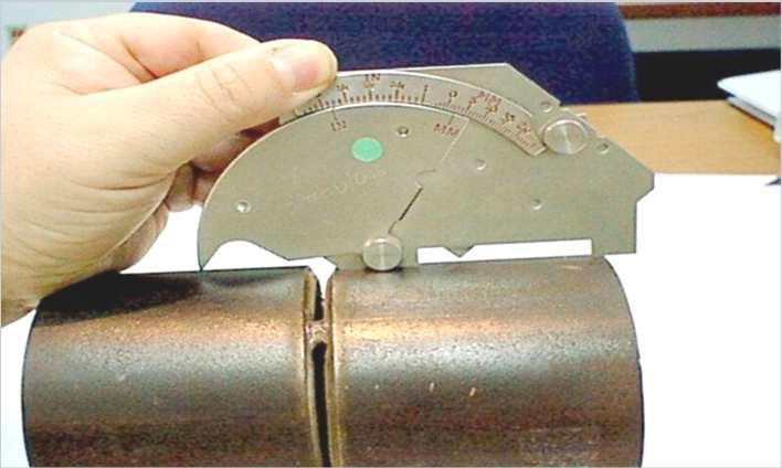

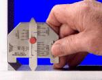
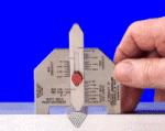
7 Misalignment Measurement Shown on scale Weld Size Gauge - by Aloke Kr. Bose, Consultant 7
8 Types of Discontinuities The types of welding discontinuities are:- Dimensional Structural Property related(chemical, Mechanical or Metallurgical) Dimensional Dimensional discontinuities refer to the interruptions in continuity of the weld size, shape, and finished dimensions. Incorrect weld size and profile along with distortion are most pronounced dimensional discontinuities that if left unattended can lead to in-service failure by fatigue or overload. Structural Structural discontinuities are those that develop within the weld during welding. They include slag inclusions, porosities, cracks, incomplete fusions, Incomplete penetrations and undercuts. Depending upon their type and extent, single or combination of those discontinuities can lead to an in- service leak or rupture in the facilities, causing an environmental and personal disaster. Property Related The most pronounced of these discontinuities are those related to welding consumables and base metal properties. Use of incorrect chemistry and/or mechanical properties of filler metals and fluxes often leads to premature in-service failure of pipeline welds. Such failures are due to weld metal cracking, high hardness and using metals susceptible to corrosion. Not all weld discontinuities are caused by improper welding conditions or welding consumables. Base metal properties that do not meet the prescribed requirements of chemical composition, mechanical properties, metallurgical structure and surface condition can result in unacceptable weld discontinuities/defects that lead to failure during fabrication or in-service. Weld Discontinuities Dimensional Structural Property Related Misalignment (hi-lo) Undercut Lamellar tearing Underfill Burn-through Laminations and Delimitations Concavity or Convexity Incomplete or Insufficient Penetration Laps and Seams Excessive reinforcement Incomplete Fusion Heat-affected zone microstructure alteration Improper reinforcement Surface irregularity Overlap Unequal fillet leg size Bulbous Contour Inclusions Slag Wagon tracks Tungsten Porosity Uniformly Scattered Cluster Linear Piping Spatter Cracks Longitudinal Transverse Crater Throat, Toe, Root Under bead and Heat-affected zone Hot, Cold or delayed - by Aloke Kr. Bose, Consultant 8


9 Common Weld Discontinuities-Porosity Causes of Porosity Base Metal contaminated Wet, unclean electrodes Insufficient or damp shielding gas Excessive arc length Welding current too high Weld speed too fast Common Weld Discontinuities-Slag Inclusions Causes of Slag Inclusion Insufficient inter-pass cleaning Unsteady travel speed Welding weave too wide Allowing slag to run ahead of the arc Using too large and electrode - by Aloke Kr. Bose, Consultant 9


10 Common Weld Discontinuities-Incomplete Penetration Causes of Incomplete Penetration Too small a root opening Too large a root face Excessive high low Travel speed too fast Welding current too low Electrode diameter too large Excessive arc length Common Weld Discontinuities-Excess Penetration Causes of Excessive Penetration Too large a root opening Too small a root face Welding current too high Travel speed too low Arc length too short - by Aloke Kr. Bose, Consultant 10


11 Common Weld Discontinuities-Incomplete Fusion Causes of Incomplete Fusion Improper electrode angle Travel speed too fast Welding current too low Faulty joint preparation Electrode diameter too large Common Weld Discontinuities-Cracks Causes of Cracks Base metal contaminated Excessive joint restraint Incorrect pre-heat Incorrect filler metal Too fast a cooling rate - by Aloke Kr. Bose, Consultant 11


12 Common Weld Discontinuities-Undercut Causes of Undercut Incorrect electrode manipulation Welding current too high Excessive arc length Travel speed too fast Common Weld Discontinuities-Tungsten Inclusions Causes of Tungsten Inclusions Contact of electrode tip with weld pool Contact of filler metal with tip of electrode Contamination of electrode Exceeding current limit for the electrode Splits or cracks in electrode - by Aloke Kr. Bose, Consultant 12

13 Cracks most unacceptable defects Cracks form in the weld and base metal when localized stresses exceeds the ultimate strength of the material. Cracking may occur at elevated temperature during weld metal solidification or after solidification,whenthe metal solidification has equalisedin temp. Cracks can be classified as either hot cracks develop at elevated temperature during solidification Or cold cracks which are develop after solidification is complete. Hot cracks propagates along the grain boundaries only but cold cracks propagates both along grains boundaries and through grains. Relation between type of loading vis-à-vis weld discontinuties Type of Defect Type of Loading Effect on Joint Porosity & Slag inclusion(isolated type) Porosity & Slag inclusion(isolated type) Porosity & Slag inclusion(arranged in linear fashion along the weld) Static Impact and vibratory load Static and repeated Reduces effective area of x-sec available for loading Weld deposits become less ductile,reduces fatigue life- critical when defects open to surface of the weld May cause total failure of the weld Not acceptable - by Aloke Kr. Bose, Consultant 13
14 Relation between type of loading vis-à-vis weld discontinuties(contd.1) Type of Defect Type of Loading Effect on Joint Cracks Static loads Source of stress concentration and reduction in available area of x-sec.- Not acceptable Lack of Fusion Static and Dynamic 5% of lack of fusion reduces fatigue limit by 23%- Not acceptable Lack of Penetration- Root for single V groove Lack of Penetration- Root for double V groove Static and Dynamic Static and Dynamic Develops failure cracks- Not acceptable The void at the centre becomes a source of weakness- Not acceptable Relation between type of loading vis-à-vis weld discontinuties(contd.2) Type of Defect Type of Loading Effect on Joint Reinforcement Static Not very critical Reinforcement Dynamic Effect fatigue life adversely and it should be machined or handground flush with the parent metal - by Aloke Kr. Bose, Consultant 14
 Liquid Penetrant Test (LPT) Radiography Test (RT) Visual Test (VT) Tensile Test Transverse Tensile Specimen All-Weld Metal Tensile Specimen - by Aloke Kr.")
15 Types of Destructive & Non-destructive Testing Destructive Non-destructive Tensile Test Charpy V-Notch Impact Test Hardness Test Fracture Test Bend Test Ultrasonic Test (UT) Magnetic Particle Test (MPT) Liquid Penetrant Test (LPT) Radiography Test (RT) Visual Test (VT) Tensile Test Transverse Tensile Specimen All-Weld Metal Tensile Specimen - by Aloke Kr. Bose, Consultant 15


 - by Aloke Kr.")
16 Charpy V-Notch Impact Test Objectives: measuring impact strength in different weld joint areas assessing resistance toward brittle fracture Information to be supplied on the test report: Material type Notch type Specimen size Test temperature Notch location Impact Strength Value Charpy V-Notch Impact Test Specimen Pendulum (striker) - by Aloke Kr. Bose, Consultant 16


17 Brinell Hardness Test Hardened steel ball of given diameter is subjected for a given time to a given load Load divided by area of indentation gives Brinell hardness in kg/mm 2 More suitable for on site hardness testing 30KN Ø=10mm steel ball Fillet Weld Fracture Tests Hammer 2mm Notch - by Aloke Kr. Bose, Consultant 17


18 Fillet Weld Fracture Tests This fracture indicates lack of fusion This fracture has occurred due to saw cut to root Bend Tests Objective of the test: To determine the soundness of the weld zone. Bend testing can also be used to give an assessment of weld zone ductility. There are three ways to perform a bend test: Root bend Face bend Side bend Side bend tests are normally carried out on welds over 12mm in thickness - by Aloke Kr. Bose, Consultant 18
19 UT- Its Principle,Application areas & Limitations Principle:-In this NDT method beams of high frequency sound waves are introduced into the material to detect surface and sub-surface flaws. The sound waves travel through the material with some attenuation of energy and are reflected at interfaces. The reflected beam is detected and analyzed to define the presence and location of any flaw. Application areas:-almost all weld discontinuties can easily be detected by the use of this technique which includes voids, cracks, inclusion etc. It is best suitable to detect planner discontinuties. Limitation:-Manual testing require careful attention by experienced technicians. Parts that are rough, irregular in shape, very thin or not homogenous are difficult to be tested. Ultrasonic Testing (Contd.) - by Aloke Kr. Bose, Consultant 19
20 Ultrasonic Testing (Contd.) MPT- Its Principle,Application areas & Limitations Principle:-It depends on the principle that when the material or part under testing is magnetized, discontinuities that lie in a direction generally transverse to the direction of the magnetic field will cause a leakage field to be formed at and above the surface of the part. Application areas:-it may be applied to all types of heavy weldments as long as the materials are magnetic.mpt is frequently used to inspect plate edges prior to welding. The purpose of this type of inspection is to detect cracks, laminations, inclusions and segregations. Limitations:-Thin coating of paint and other nonmagnetic covering adversely affect sensitivity of this test. This method will work only on ferromagnetic materials. Demagnetizing following the test is often necessary. - by Aloke Kr. Bose, Consultant 20
 RT- Its Principle,Application areas & Limitations Principle:-This method is based on the principle of differential absorption of penetrating electromagnetic radiation")

21 Magnetic Particle Test (Contd.) RT- Its Principle,Application areas & Limitations Principle:-This method is based on the principle of differential absorption of penetrating electromagnetic radiation of very short wave length. Application areas:-it is extensively used for detecting almost all types of weld defects.it is best for detecting voluminous defects.both ferrous, non-ferrous metals/non-metallic materials and composites can be tested by this method. Limitations:-Compared to other NDT methods, it is expensive.high activity source require heavy shielding for protection of personnel.laminations are impossible to detect with this method. - by Aloke Kr. Bose, Consultant 21
22 Radiography Testing(Contd.) Radiography Testing (Contd.) - by Aloke Kr. Bose, Consultant 22
23 Radiography Testing (Contd.) LPT- Its Principle, Application areas & Limitations Principle Application Areas Limitations In this method the liquid penetrant seep into various types of minute surface openings(as fine as 4 micro inch in width) by capillary action It is used extensively for testing of weld defects of wrought and cast products of both ferrous and nonferrous metals. Surface defects as cracks, porosity etc. on the surface and mainly chip back testing of weldments during multipass welding. The major limitation of this method of testing is that it can detect those discontinuities that are open to surface. It is restricted to non porous metals/nonmetals only. - by Aloke Kr. Bose, Consultant 23
24 Liquid Penetant Test (Contd.) Liquid Penetrant Test (Contd) - by Aloke Kr. Bose, Consultant 24
25 VT- Its Principle,Application areas & Limitations Principle Application Areas Limitations It utilizes the most sensitive organ of our body i.e. eyes for detecting and evaluating surface defects. For detection of following surface weld defects. Cracks Surface Irregularities. Contour Defects and Root Defects It is restricted to exposed or accessible surface and discontinuities of opaque materials only. Classification of Imperfections ( Discontinuities) as per ISO :2007 In order to avoid any confusion, different type of weld imperfections (Discontinuities) are very systemically numbered and defined with explanations and illustrations in ISO As per ISO the numbering system of different weld imperfections (Discontinuities) have been classified into six main groups. Cracks Cavities Solid inclusions Lack of fusion and penetration Imperfect shapes and dimensions Miscellaneous imperfections - by Aloke Kr. Bose, Consultant 25
26 Few Examples of Discontinuities as per ISO Sl. Nos. Classifications Basic Code Nos. Sub Code Nos. (Few Examples) Explanation of Sub cod Nos. 1 Cracks Cavities Solid Inclutions LOFs & IPs Longitudinal Cracks Transverse Cracks Crater Cracks Gas Cavity Shrinkage Cavity Micro-shrinkage Slag Inclusion Flux Inclusion Metallic inclusion Lack of fusion Incomplete Penetrations Spiking 5 ISs and IDs Undercut Excessive Penetration Burn -through 6 Misc. Imperfections Arc Strike Spatter Slag Residue Acceptance standards as per ISO 5817:2003 This standard provides quality levels of imperfections (discontinuities) in fusion-welded joints in all types of steel, nickel, titanium and their alloys. It is applicable to material thickness above 0.5 mm thickness. It covers full penetration butt welds and all fillet welds. As per this standard the quality levels are designated in three different classes, B,C and D. Quality level B corresponds to highest quality requirement on finished weld while D corresponds to the lowest. Requirements as per this standard have been illustrated in the following few tables. - by Aloke Kr. Bose, Consultant 26


27 Acceptance standards as per ISO 5817:2003- Example 1 Acceptance standards as per ISO 5817:2003- Example 2 - by Aloke Kr. Bose, Consultant 27
28 Inspection and Testing of Welds & Acceptance standards as per ISO 5817:2003Example 3 Acceptance standards as per ISO 5817:2003Example 4 - by Aloke Kr. Bose, Consultant 28
29 Inspection and Testing of Welds & Acceptance standards as per ISO 5817:2003Example 5 Acceptance standards as per ISO 5817:2003Example 6 - by Aloke Kr. Bose, Consultant 29
30 Conclusion We know that ISO 9001 standard specifies requirement for a quality management system where an organization needs to demonstrate its ability to provide consistency in there product/services that meets customer s need and regulatory requirement as well as enhance customer s satisfaction with an approach for continual improvement of its processes and product/services. As per Cl. No of ISO 9001 Welding is considered as a special process where result of this process cannot be fully verified by subsequent inspection and testing of the product and processing deficiencies may become apparent only after the product is in use, hence qualitative and quantitative measurement of this process is a must to achieve desired quality assurance. Hence, ISO 3834 defines various approaches to quality requirements for welded fabrication, both in work-shops and on sites and provide guidance for describing the ability of a manufacturer to produce welded constructions of agreed and specified quality. More over this standard has been in force in most of the developed countries for all welding related manufacturing products. In order to adhere to the above objectives an organization should adopt different quality level depending on the criticality of the product as described in ISO 5817 and understand discontinuities classifications as per ISO ISO 9606 which is considered to be less complex than that of ASME Sec.IX may be adopted for preparation of WPS, PQR and WPQ in future which is mandatory as per ISO Thank You for your patient hearing. - by Aloke Kr. Bose, Consultant 30
Welding Inspection Defects/Repairs Course Reference WIS 5
 Copy from Welding Inspection Defects/Repairs Course Reference WIS 5 Weld Defects Defects which may be detected by visual inspection can be grouped under five headings Cracks Surface irregularities Contour
Defects and Discontinuities. Tim Turner Elizabethtown Technical College
 Defects and Discontinuities Tim Turner Elizabethtown Technical College Defect A flaw or flaws that by nature or accumulated effect render a part or product unable to meet minimum applicable acceptance
Defect. Discontinuity. Defects and Discontinuities. Weld Joint Discontinuities
 Defects and Discontinuities Defect A flaw or flaws that by nature or accumulated effect render a part or product unable to meet minimum applicable acceptance standards or specifications. The term designates
Weld Imperfections and Preventive Measures
 FOURTH EDITION Weld Imperfections and Preventive Measures Published by FOURTH EDITION Weld Imperfections and Preventive Measures Kita-Shinagawa, Shinagawa-Ku, Tokyo, 141-8688 Japan Published by KOBE STEEL,
Planning Advisory Notice
 This Planning Advisory Notice (PAN) is a follow up to the PAN from the March/April issue. In that PAN we discussed some of the codes, standards, and specifications that apply to proper welding design,
Discontinuities and Defects
 Discontinuities and Defects 1 Discontinuity Is An interruption of the typical structure of a material, such as a lack of homogeneity in its mechanical, metallurgical, or physical characteristics. A discontinuity
NAME 345 Welding Technology Lecture 12 Welding Defects & Discontinuities
 NAME 345 Welding Technology Lecture 12 Welding Defects & Discontinuities Md. Habibur Rahman Lecturer Department of Naval Architecture & Marine Engineering Bangladesh University of Engineering & Technology
AWS B1.10:1999 An American National Standard. Guide for the Nondestructive Examination of Welds
 AWS B1.10:1999 An American National Standard Guide for the Nondestructive Examination of Welds Key Words Guide, eddy current examination, magnetic particle examination, nondestructive examination, penetrant
ME E5 - Welding Metallurgy
 ME 328.3 E5 - Welding Metallurgy Purpose: To become more familiar with the welding process and its effects on the material To look at the changes in microstructure and the hardness in the Heat Affected
Welding. What is Welding?
 Welding Welding What is Welding? Welding is a joining process in which metals are heated, melted and mixed to produce a joint with properties similar to those of the materials being joined. Parent Metal
Sub-surface inspection of welds No. 6.03
 Sub-surface inspection of welds Scope This Guidance Note applies to all welds in structural steelwork for bridges. It covers the sub-surface inspection of welds using ultrasonic inspection testing and
Manufacturing Process - I Dr. D. K. Dwivedi Department of Mechanical and Industrial Engineering Indian Institute of Technology, Roorkee
 Manufacturing Process - I Dr. D. K. Dwivedi Department of Mechanical and Industrial Engineering Indian Institute of Technology, Roorkee Module - 3 Lecture - 14 Reaction in Weld Region & Welding Defects
Nondestructive Testing
 Nondestructive Testing Prof. A.K.M.B. Rashid Department of MME BUET, Dhaka Nondestructive inspections fundamentals Classification of nondestructive inspections Radiographic inspection Magnetic particle
1. IMPERFECTIONS OF THE WELDED CONNECTION
 1. IMPERFECTIONS OF THE WELDED CONNECTION A. Classification of imperfections in the welds acc. to EN 26520 (ISO 6520) Crack (100) - imperfection produced by a local rupture in the solid state which can
DISCONTINUITIES AND DEFECTS. Training Workbook
 DISCONTINUITIES AND DEFECTS Training Workbook EW-512-4 Written by the Staff of Hobart Institute of Welding Technology Additional copies can be obtained from: Hobart Institute of Welding Technology 400
Welding Defects, Causes and Prevention
 Welding Defects, and In welding the important objective is to obtain sound, defect free weld joint. But it is not always possible to get defect free joint. There will always be some kind of defects in
QC Inspection and Qualification Procedure- TX-EDU-VT-1-07, Revision # by Richard J DePue, Supersedes IW-VT-1 Visual Inspection Procedure
 1.0 Scope: QC Inspection and Qualification Procedure- TX-EDU-VT-1-07, Revision #6 03-04-2016 by Richard J DePue, Supersedes IW-VT-1 Visual Inspection Procedure The purpose of this procedure is to define
WELDER S. Visual Inspection HANDBOOK. May 2013
 WELDER S Visual Inspection HANDBOOK May 2013 -- NOTE -- This handbook is NOT intended to serve as a work procedure or to replace any existing procedures. It is solely intended to provide basic information
Weld Quality Standards
 Weld Quality Standards 9/14/2011 1 Index Visual Inspection Criteria Using a Fillet Weld Gage Measuring Weld Reinforcement for a Groove Weld Welding Technique Information Sheets 9/14/2011 2 Visual Inspection
Course: Quality Assurance Module 5 Welders/Welding personnel
 Version 1.0 2010.11.02 1 of 7 Course: Quality Assurance Module 5 Welders/Welding personnel Version 1.0 2010.11.02 2 of 7 Table of Contents MODULE 5...3 Surface inspection on cracks and other surface imperfections
AWS B1.10M/B1.10:2009 An American National Standard. Guide for the Nondestructive Examination of Welds
 An American National Standard Guide for the Nondestructive Examination of Welds An American National Standard Approved by the American National Standards Institute July 1, 2009 Guide for the Nondestructive
welding equipment Prepare and use manual TIG or plasma-arc Performance evidence required You must be able to:
 006 UNIT 028 Preparing and using manual TIG or plasma-arc Learning outcomes 1 2 Know how to prepare and use manual TIG or plasma-arc Performance evidence must be the main form of evidence gathered. Candidates
NAME 345 Welding Technology Lecture 03 (Welding Joint Design)
") NAME 345 Welding Technology Lecture 03 (Welding Joint Design) Md. Habibur Rahman Lecturer Department of Naval Architecture & Marine Engineering Bangladesh University of Engineering & Technology Dhaka-1000,
NAME 345 Welding Technology Lecture 03 (Welding Joint Design) Md. Habibur Rahman Lecturer Department of Naval Architecture & Marine Engineering Bangladesh University of Engineering & Technology Dhaka-1000,
Preparing and using manual metal arc welding equipment
 Unit 827 Preparing and using manual metal arc welding equipment UAN: J/600/5889 Level: Level 2 Credit value: 15 GLH: 68 Relationship to NOS: Endorsement by a sector or regulatory body: Aim: This unit has
Procedure for Visual and Optical Inspection
 Procedure for Visual and Optical Originator Benjamin Boudreaux, ASNT NDT Level III, cert. 148993, UT, MT, PT, VT Date Aug. 08, 2016 Approval Corey Navarro, President Date Aug. 08, 2016 Page 1 8 Revision
Saggistica Aracne 266
 Saggistica Aracne 266 Moreno Preto Welding Defects Copyright MMXIII ARACNE editrice S.r.l. www.aracneeditrice.it info@aracneeditrice.it via Raffaele Garofalo, 133/A B 00173 Roma (06) 93781065 ISBN 978-88-548-5854-1
1. Poor attitude toward any of the other students, instructors, or judges. 2. Failure to use personal protective equipment (PPE).
.") Welding Contest Rules and Score Sheet 2016 4G Rules: 1. Be Safe & Have Fun 2. Can tack in any position but groove welding must be in accordance with your WPS. 3. Can use wire brush, chipping hammer, and
Welding Contest Rules and Score Sheet 2016 4G Rules: 1. Be Safe & Have Fun 2. Can tack in any position but groove welding must be in accordance with your WPS. 3. Can use wire brush, chipping hammer, and
INSPECTION AND TEST. PROCEDURE Total Page 13
 PROCEDURE Total Page 13 Client : Project Name: P/O No. : Item No. : 3 2 1 0 FOR APPROVAL Rev Description Date Prepared By Checked By Approved By PROCEDURE Page 1 of 8 1. General 1.1 Scope This specification
Preparing and using manual TIG or plasma-arc welding equipment
 Unit 028 Preparing and using manual TIG or plasma-arc welding equipment Level: 2 Credit value: 15 NDAQ number: 500/9514/6 Unit aim This unit covers the skills and knowledge needed to prove the competences
Table of Contents Page No.
 Table of Contents Page No. Personnel... iii Foreword...v List of Tables...xii List of Figures... xiii 1. General Requirements...1 1.1 Scope...1 1.2 Approval...1 1.3 Definitions...1 1.4 Welding Symbols...1
Welding Efficiency & Learning Defects (W.E.L.D) Cards A
 Cards A") Welding Efficiency & Learning Defects (W.E.L.D) Cards 1033480-01A Ideal weld path and look for tee and butt joints Definition The proper weld filament, consistent path and fusion. Tee Joint V-Groove Joint
Welding Efficiency & Learning Defects (W.E.L.D) Cards 1033480-01A Ideal weld path and look for tee and butt joints Definition The proper weld filament, consistent path and fusion. Tee Joint V-Groove Joint
Welding Job Knowledge
 Defects - lamellar tearing BP Forties platform lamellar tears were produced when attempting the repair of lack of root penetration in a brace weld Lamellar tearing can occur beneath the weld especially
PART I PERFORMANCE OF MATERIALS IN SERVICE. Materials and Process Selection for Engineering Design: Mahmoud Farag
 PART I PERFORMANCE OF MATERIALS IN SERVICE 1 Performance of Materials in Service I Part I discusses the different types of failure and how to prevent, or at least delay, such failures by selecting appropriate
Module 4 Design for Assembly
 Module 4 Design for Assembly Lecture 2 Design for Welding-I Instructional Objective By the end of this lecture, the student will learn: (a) how a weld joint should be designed to improve the joint performance,
Introduction to Welding Technology
 Introduction to Welding Technology Welding is a fabrication process used to join materials, usually metals or thermoplastics, together. During welding, the pieces to be joined (the workpieces) are melted
Porosity The good, the Bad and the Ugly of Radiographic Testing
 19 th World Conference on Non-Destructive Testing 2016 Porosity The good, the Bad and the Ugly of Radiographic Testing Hugo VAUGHAN 1 1 South African Institute of Welding, Johannesburg, South Africa Contact
NATURAL GAS COMPRESSOR STATION PIPELINE WELDING AND RELATED FACILITIES. Engr. Md. Saidur Rahman 1,*
 Proceedings of the International Conference on Mechanical Engineering and Renewable Energy 2015 (ICMERE2015) 26 29 November, 2015, Chittagong, Bangladesh ICMERE2015-PI-243 NATURAL GAS COMPRESSOR STATION
Lecture 29 DESIGN OF WELDED JOINTS VII
 Lecture 29 DESIGN OF WELDED JOINTS VII This chapter presents the influence of various welding related parameters on fatigue behavior of weld joints. Attempts have been made to explain how (residual stress,
Table of Contents Page No.
 Table of Contents Personnel... iii Foreword...v List of Tables... xiii List of Figures...xiv List of Forms...xvi 1. General Provisions...1 1.1 Application...1 1.2 Base Metal...1 1.3 Welding Processes...2
49 CFR Part 192. Not applicable to welding during manufacture of pipe and components
 49 CFR Part 192 Not applicable to welding during manufacture of pipe and components --- and other strange nomenclature A joining process that produces a coalescence of metals (or non-metals) by heating
Welding of Large Diameter Pipelines: Design, Processes, Procedures Specifications for Welding Steel Water Pipe
 Welding of Large Diameter Pipelines: Design, Processes, Procedures Specifications for Welding Steel Water Pipe Field Welding of Steel Pipe Joints Nash Williams, Owner National Welding Corporation 2 Steel
ISO INTERNATIONAL STANDARD. Non-destructive testing of welds Visual testing of fusion-welded joints
 INTERNATIONAL STANDARD ISO 17637 First edition 2003-07-15 Non-destructive testing of welds Visual testing of fusion-welded joints Contrôle non destructif des assemblages soudés Contrôle visuel des assemblages
AASHTO/AWS D1.5M/D1.5:2008. Table of Contents
 Table of Contents Personnel...v Foreword...ix List of Tables... xviii List of Figures...xix List of Forms...xxi 1. General Provisions...1 1.1 Application...1 1.2 Base Metal...1 1.3 Welding Processes...1
INSPECTION OF FIELD WELDING
 INSPECTION OF FIELD WELDING Objective Types of Projects Involving Welding Common Welding Terms & Symbols Welder Qualifications Common Welding Requirements Welding Inspection Types of Projects Involving
AN OVERVIEW ON SHIELDED METAL ARC WELDING (SMAW) OF STAINLESS STEEL (SS)
 OF STAINLESS STEEL (SS)") Suggested Spec. for SMAW-SS - 1 - AN OVERVIEW ON SHIELDED METAL ARC WELDING (SMAW) OF STAINLESS STEEL (SS) Scope This document provides information on welding and related operations of stainless steel
Suggested Spec. for SMAW-SS - 1 - AN OVERVIEW ON SHIELDED METAL ARC WELDING (SMAW) OF STAINLESS STEEL (SS) Scope This document provides information on welding and related operations of stainless steel
Fundamentals of Joining
 Fundamentals of Joining Chapter 30 30.1 Introduction to Consolidation Processes Consolidation Processes consist of Welding Brazing Soldering Fasteners Adhesives Shrink Fits Slots and Tabs Each Process
Modeling Welded. ANSYS e-learning. June CAE Associates
 Modeling Welded Connections ANSYS e-learning Peter Barrett June 2013 2013 CAE Associates Outline The importance of weld stress prediction. Weld geometry and terminology. Failure due to fatigue. Methods
Fillet welded joints - a review of the practicalities
 1 of 7 5/13/2006 10:52 AM The Professional Division of The Welding Institute Home Membership Members only WJS Education Training Technical info Links JoinIT Contact us Search Fillet welded joints - a review
Cast Steel Propellers W27. (May 2000) (Rev.1 May 2004)
 (Rev.1 May 2004)") (May 2000) (Rev.1 May 2004) Cast Steel Propellers 1. Scope 1.1 These unified requirements are applicable to the manufacture of cast steel propellers, blades and bosses. 1.2 Where the use of alternative
(May 2000) (Rev.1 May 2004) Cast Steel Propellers 1. Scope 1.1 These unified requirements are applicable to the manufacture of cast steel propellers, blades and bosses. 1.2 Where the use of alternative
Comparison of BS and BS EN for steel materials
 Comparison of BS and BS EN for steel materials Appendix This table only highlights the comparison of BS and BS EN on steel materials, which are relevant to plan approval. Title of BS BS BS EN Title of
CHAPTER 3: TYPES OF WELDING PROCESS, WELD DEFECTS AND RADIOGRAPHIC IMAGES. Welding is the process of coalescing more than one material part at
 41 CHAPTER 3: TYPES OF WELDING PROCESS, WELD DEFECTS AND RADIOGRAPHIC IMAGES 3.0. INTRODUCTION Welding is the process of coalescing more than one material part at their surface of contact by the suitable
Common Oxy Fuel Industry Terms
 Common Oxy Fuel Industry Terms A ACETYLENE Gas composed of two parts of carbon and two parts of hydrogen When burned in the atmosphere of oxygen, it produces one of the highest flame temperatures obtainable.
SPECIMEN WRITTEN EXAMINATION QUESTIONS
 SPECIMEN WRITTEN EXAMINATION QUESTIONS CSWIP 3.1 1.1 Part A and Part A2 Candidates are required to tick, or otherwise indicate, the corrective answer in the section provided. There is only one correct
TESTING OF MANUAL ARC WELDERS Issue No 5 Date Issued 1/9/69
 NEW ZEALAND PRACTICAL TRAINING AND TESTING OF MANUAL ARC WELDERS Issue No 5 Date Issued 1/9/69 GOVERNMENT RAILWAYS Page No. 1 of 6 1. GENERAL: This Code is to be brought to the attention of all staff trained
WELD TESTING DESTRUCTIVE AND NON-DESTRUCTIVE
 WELD TESTING DESTRUCTIVE AND NON-DESTRUCTIVE DESTRUCTIVE TESTING These can be divided into two parts, Tests capable of being performed in the workshop. Laboratory tests. microscopicmacroscopic, chemical
ISO 5817 INTERNATIONAL STANDARD
 INTERNATIONAL STANDARD ISO 5817 Second edition 2003-10-01 Welding Fusion-welded joints in steel, nickel, titanium and their alloys (beam welding excluded) Quality levels for imperfections Soudage Assemblages
ENGINEERING STANDARD PENETRANT ACCEPTANCE CRITERIA ES Prepared by: H. HOPKINSON Date: Reviewed by: J. MOELLER Date:
 ENGINEERING STANDARD ES 2012 Prepared by: H. HOPKINSON Date: 12-21-90 Reviewed by: J. MOELLER Date: 12-27-90 Approved by: J. D. MOELLER Date: 12-27-90 John D. Moeller Director of Engineering 1 REVISIONS
PART UF REQUIREMENTS FOR PRESSURE VESSELS FABRICATED BY FORGINGS
 p 1 of 6 UF-1 UF-12 PART UF REQUIREMENTS FOR PRESSURE VESSELS FABRICATED BY FORGING the test temperature be higher than 20 F ( 29 C). Certification is required. An ultrasonic examination shall be made
Nondestructive Examination
 Nondestructive Examination by Roger Cantrell Learning Objectives This course introduces the student to the basic concepts of six Nondestructive Examination (NDE) methods used in construction and periodic
A Practical Design Guide for Welded Connections Part 1 Basic Concepts and Weld Symbols
 A Practical Design Guide for Welded Connections Part 1 Basic Concepts and Weld Symbols by James Doane, PhD, PE Course Overview This course is divided into 2 parts. Though it provides some basic concepts
BONDING, POTTING, WELDING
 40-60 Delaware St. BONDING, POTTING, WELDING Part No. PR303 - INDEX- : 5/17/05 This Quality Standard applies unless otherwise specified by drawing or specification. PAGE 1 : INDEX PAGE 2 : DEFINITIONS
Structural Steel Welding
 PDH Course S150 Structural Steel Welding Semih Genculu, P.E. 2011 PDH Online PDH Center 5272 Meadow Estates Drive Fairfax, VA 22030-6658 Phone & Fax: 703-988-0088 www.pdhonline.org www.pdhcenter.com An
NAME 345 Welding Technology Lecture 09 SAW, ESW & Resistance Welding
 NAME 345 Welding Technology Lecture 09 Md. Habibur Rahman Lecturer Department of Naval Architecture & Marine Engineering Bangladesh University of Engineering & Technology Dhaka-1000, Bangladesh Submerged
RULES. PUBLICATION No. 74/P PRINCIPLES FOR WELDING PROCEDURE QUALIFICATION TESTS March
 RULES PUBLICATION No. 74/P PRINCIPLES FOR WELDING PROCEDURE QUALIFICATION TESTS 2018 March Publications P (Additional Rule Requirements) issued by Polski Rejestr Statków complete or extend the Rules and
b) provide evidence of his qualifications and practical experience in welding.
 provide evidence of his qualifications and practical experience in welding.") NEPALESE CIVIL AIRWORTHINESS REQUIREMENTS SECTION D APPROVAL PROCEDURES CHAPTER D.6 ISSUE 1 NOVEMBER 1994 1. GENERAL WELDERS 1.1 This chapter is applicable to persons who weld parts which are essential
NEPALESE CIVIL AIRWORTHINESS REQUIREMENTS SECTION D APPROVAL PROCEDURES CHAPTER D.6 ISSUE 1 NOVEMBER 1994 1. GENERAL WELDERS 1.1 This chapter is applicable to persons who weld parts which are essential
PART 5 WELDING. 5.1 General 5.2 Preparation 5.3 Dimensions of welds 5.4 Materials 5.5 Aluminium alloys 5.6 Welding details 5.
 PART 5 WELDING PART 5 WELDING SECTION SUBJECT 5.1 General 5.2 Preparation 5.3 Dimensions of welds 5.4 Materials 5.5 Aluminium alloys 5.6 details 5.7 Symbols WELDING Section 5.1 General 5.1.1 of structures
DOWNLOAD PDF SMAW : BEADS AND FILLET WELDS
 Chapter 1 : SMAW Fillet Welds?!!! - Miller Welding Discussion Forums View Notes - SMAW -beads and fillet weldsterm: Definition: wire brush or grinder used to remove heavy mill scale or corrosion from coupons
WELDING PROCEDURE SPECIFICATION. Shielded Metal Arc Welding-SMAW
 WELDING PROCEDURE SPECIFICATION Shielded Metal Arc Welding-SMAW WPS Number: WPS-SMAW-CS Revision: 0 Company Name & Address ABC WELDING & FABRICATING 123 WeldProc Boulevard Toronto, ON A1B 2C3 CWB Approval
BOOK OF SPECIFICATIONS
 American Welding Society CERTIFICATION www.aws.org CERTIFIED WELDING INSPECTOR (CWI) PART B PRACTICAL EXAMINATION BOOK OF SPECIFICATIONS JANUARY 1, 2016 January 1, 2016 This page is intentionally blank.
PILE WELDING QUALITY CONTROL PLAN
 Michigan Department Of Transportation 5627 (10/14) PILE WELDING QUALITY CONTROL PLAN CONTRACTOR LOCATION PREPARED BY CONTROL SECTION JOB NO. DATE Bridge Field Services Approval Block CHECKED BY DATE SPECIFICATIONS
RULES FOR THE CLASSIFICATION OF SHIPS
 RULES FOR THE CLASSIFICATION OF SHIPS 2009 Part 26 - WELDING Amendments No.1 CROATIAN REGISTER OF SHIPPING Hrvatska (Croatia) 21000 Split Marasovićeva 67 P.O.B. 187 Tel.: (...) 385 (0)21 40 81 11 Fax.:
Capstone C O N S U L T A N T S
 Ultrasonic Pulse Velocity Tests These tests are primarily done to establish: the homogeneity of concrete presence of cracks, voids and other imperfections changes in quality of concrete over time this
Item 448 Structural Field Welding
 Item 448 Structural Field Welding 1. DESCRIPTION 2. MATERIALS Field-weld metal members using the shielded metal arc or flux cored arc welding processes. Provide electrodes for shielded metal arc welding
METROPOLITAN. O & M Procedure No: E UTILITIES DISTRICT I. GENERAL
 Page: 1 of 10 I. GENERAL * Before any welder may weld on the Metropolitan Utilities District gas distribution and transmission system piping and facilities, the welder shall be qualified to perform the
SPECIAL PROVISION FOR STRUCTURAL STEEL AND ALUMINUM CONSTRUCTION. C&T:SJC 1 of 10 C&T:APPR:DAJ:DBP: FHWA:APPR:
 MICHIGAN DEPARTMENT OF TRANSPORTATION SPECIAL PROVISION FOR STRUCTURAL STEEL AND ALUMINUM CONSTRUCTION C&T:SJC 1 of 10 C&T:APPR:DAJ:DBP:07-09-07 FHWA:APPR:07-19-07 a. Description. This specification covers
Technical Specification for Fabrication, Testing & Supply of Back plate assembly mock-up
 INSTITUTE FOR PLASMA RESEARCH (An Autonomous Institute of Department of Atomic Energy, Government of India) Near Indira Bridge; Bhat; Gandhinagar-382428; India PART-I (B) Technical Specification for Fabrication,
Standard Specification for Ferritic/Austenitic (Duplex) Stainless Steel Pipe Electric Fusion Welded with Addition of Filler Metal 1
 Stainless Steel Pipe Electric Fusion Welded with Addition of Filler Metal 1") Designation: A 928/A 928M 04 www.tubingchina.com Standard Specification for Ferritic/Austenitic (Duplex) Stainless Steel Pipe Electric Fusion Welded with Addition of Filler Metal 1 This standard is issued
Designation: A 928/A 928M 04 www.tubingchina.com Standard Specification for Ferritic/Austenitic (Duplex) Stainless Steel Pipe Electric Fusion Welded with Addition of Filler Metal 1 This standard is issued
Extended stickout guides are used to maintain a consistent CTWD (see Contact Tip to Work Distance section for more details).
.") WELDING TECHNIQUES Extended Stickout Welding (Cont d) Extended stickout welding is best suited to large diameter, high deposition Innershield electrodes, such as 3/32 in. (2.4 mm) and 0.120 in. (3.0 mm)
WELDING TECHNIQUES Extended Stickout Welding (Cont d) Extended stickout welding is best suited to large diameter, high deposition Innershield electrodes, such as 3/32 in. (2.4 mm) and 0.120 in. (3.0 mm)
Lecture No. # 37 Welding Defects and NDT
 Marine Construction and Welding Prof. Dr. N. R. Mandal Department of Ocean Engineering and Naval Architecture Indian Institute of Technology, Kharagpur Lecture No. # 37 Welding Defects and NDT So, continuing
CP25 ANNEX A - GENERAL SPECIFICATION FOR VISUAL TESTING
 Certification Services Division Midsummer House Riverside Way, Bedford Road Northampton, NN1 5NX United Kingdom Tel: +44(0)1604-438-300. Fax: +44(0)1604-438-301. E-mail: pcn@bindt.org CP25 ANNEX A - GENERAL
GENERAL FUSION WELDING REQUIREMENTS FOR AEROSPACE MATERIALS USED IN FLIGHT HARDWARE
 METRIC/ INCH-POUND National Aeronautics and Space Administration FEBRUARY 17, 1999 GENERAL FUSION WELDING REQUIREMENTS FOR AEROSPACE MATERIALS USED IN FLIGHT HARDWARE NASA TECHNICAL STANDARD FOREWORD
Subpart E Welding of Steel in Pipelines
 Subpart E Welding of Steel in Pipelines 192.221 Scope This subpart prescribes minimum requirements for welding steel materials in pipelines. This subpart does not apply to welding that occurs during the
WELDING TECHNOLOGY AND WELDING INSPECTION
 WELDING TECHNOLOGY AND WELDING INSPECTION PRESENTED BY: GOPAL KUMAR CHOUDHARY SVL ENGINEERING SERVICES CHENNAI CONTENTS: DEFINATION TYPES OF WELDING ELECTRODE GEOMETRY EQUIPMENT QUALITY PROCESS SAFETY
ITEM 448 STRUCTURAL FIELD WELDING
 ITEM 448 STRUCTURAL FIELD WELDING 448.1. Description. This Item shall govern for the field welding of structural steel, reinforcing steel, and miscellaneous steel items as shown on the plans and in accordance
Inspection of Steel Girder Bridges
 Course Outline Inspection of Steel Girder Bridges Bridge superstructure systems Defects in steel members Failure mechanics Fatigue Constrained Induced fracture (CIF) Inspection Inspection of Pin & Hanger
ASTM Standards for Pipe & Fittings
 for Pipe & Fittings There are many International Standards for stainless and carbon steel pipes and fittings. The list below is a basic overview of some of these. For more in-depth details of these Standards
pdfmachine trial version
 EFFECT OF WELDING TECHNIQUES (GTAW & SMAW) ON THE MICROSTRUCTURE & MECHANICAL PROPERTIES OF MILD STEEL SA 516 Gr. 70 By Dr. Muhammad Taqi Zahid Butt, S. Ahmed, S. Rasool, U. Ali and S. U. Rehman* ABSTRACT
FABRICATION/WELDING STANDARD MANUAL
 This manual was produced for internal use at Geringhoff Manufacturing LLC. We strongly recommend our suppliers to read and adhere to it. It is of great help to understand our drawings and our expectations.
CONSTRUCTION SPECIFICATION FOR STRUCTURAL STEEL
 ONTARIO PROVINCIAL STANDARD SPECIFICATION METRIC OPSS 906 FEBRUARY 1993 CONSTRUCTION SPECIFICATION FOR STRUCTURAL STEEL 906.01 SCOPE 906.02 REFERENCES 906.03 DEFINITIONS TABLE OF CONTENTS 906.04 SUBMISSION
Q = N + 1 Basic Quality Assurance for Structural Steel
 Q = N + 1 Basic Quality Assurance for Structural Steel Philip E. Fish & David M. Boldt Fish & Associates, Inc. April 27, 2012 SEND COMMENTS TO: dboldt@fishassoc.com Presentation Outline Philosophy (of
Lecture 24. Keywords: Selecting groove geometry, fillet weld, bead weld, dilution, stress concentration, plug weld, weld bead geometry
 Lecture 24 DESIGN OF WELDED JOINTS III This chapter describes the factors affecting the selection of suitable groove geometry for edge preparation and influence of welding parameters on weld bead geometry.
NAME 345 Welding Technology Lecture 07 Shielded Metal Arc Welding (SMAW)
") NAME 345 Welding Technology Lecture 07 Shielded Metal Arc Welding (SMAW) Md. Habibur Rahman Lecturer Department of Naval Architecture & Marine Engineering Bangladesh University of Engineering & Technology
NAME 345 Welding Technology Lecture 07 Shielded Metal Arc Welding (SMAW) Md. Habibur Rahman Lecturer Department of Naval Architecture & Marine Engineering Bangladesh University of Engineering & Technology
SECOND SEMESTER DIPLOMA EXAMINATION IN MECHANICAL ENGINEERING- MARCH, 2015 MANUFACTURING PROCESS PART-A
 SECOND SEMESTER DIPLOMA EXAMINATION IN MECHANICAL ENGINEERING- MARCH, 2015 MANUFACTURING PROCESS PART-A 1. Define hardness. It is the ability of a material to resist indentation or surface abrasion 2.
OIL TECH SERVICES, INC.
 OIL TECH SERVICES, INC. 800 Wilcrest, Suite 100 Houston, TX 77042-1359 (310)-527-2695 (713) 789-5144 E Mail: mlombard@itmreps.com Website: www.itmreps.com WELDING Weld Procedure Specifications (WPS): Welding