Risering System Design
|
|
|
- Shawn Williams
- 6 years ago
- Views:
Transcription
1 Section two Risering System Design Please note: Risering must be done before gating system can be calculated. Bottle shaped (Heine) risers are now the riser of choice in the majority of systems. 19
2 2.0 RISERING SYSTEM DESIGN 2.1 Objectives: castings without shrinkage defects economic production maximize casting yield 2.2 Essential Components Riser always blind (closed top). Riser contact generally as short as possible. Designed dimensions always measured at the notch. Gate thin and wide for fast freezing (see p. 28). Vents to assist fast mould filling. 2.3 The Following are Suggested by Research and Supported by Industrial Experience Volume change patterns of cooling and solidifying graphitic irons result in net volume increase of iron in the mould. The net volume increase can produce liquid pressure in the mould of several hundred p.s.i. (2 MPa). This pressure always exceeds the elastic limit of the mould, except for very rigid moulds, leading to mould enlargement and swollen castings, often containing shrinkage defects. Green sand moulds are not considered to be rigid in this context. Riser function is very sensitive to pouring temperature and pouring time. Volume change pattern is not constant but varies according to cooling rate and liquid iron processing route (superheat, charge composition, melting method, inoculation, etc). Due to the high pressures experienced by the mould during pouring and solidification, mould halves should be clamped together. Weighting alone is not sufficient. 20
3 2.4 Typical Volume Change Patterns General volume change pattern for steel, white iron, brass, etc. Specific Volume (cm 3 /g) (in 3 /lb) Solidification (Freezing) Contraction Rate of solid State Contraction Temperature Interval of Solidification Temperature ( C, F) Volume change patterns for graphitic irons. Temperature of the Liquid after Completed Pouring. (Ty) Primary (Liquid) Contraction Shape of volume change pattern influenced by cooling rate and by changes in liquid iron processing. This directly affects the extent of contraction and expansion. 2.5 Planning The detailed design principles will be presented in the following order: Determine significant modulus of the castings (M S ). Evaluate mould and iron quality, then select appropriate risering method. Determine corresponding liquid transfer modulus (M N ) and number of risers required for each casting. Select riser type and compute dimensions (M R ). Select riser contact (neck) type and compute dimensions. Check that available feed volume in riser(s) is sufficient for casting s requirements. Select pouring temperature based on selected risering method. Cooling liquid initially contracts then expands. Towards the end of solidification, last remaining liquid solidifies with contraction. 21
4 2.6 Cooling Rate Casting weight or wall thickness not sufficiently accurate to describe cooling rate. Simple shapes: cube, plate, bar etc, all 1 inch (25 mm) thick but all cool at different rates. Use modulus (M) to describe cooling. Modulus = volume effective cooling surface area More complicated shapes should be broken down into simple shapes and the moduli of the individual simple shapes, determined. Note in the example that the connecting surfaces between adjacent segments are not considered to contribute to cooling (variable c below). Where: V = total casting volume. CSA = total cooling surface area of the casting Example for the calculation of Modulus a = any side b = any side c = non-cooled side 2. Modulus = V M = a b CSA 2 (a + b) c all dimensions in cm M 1 M 2 M 3 = = 1.0 cm 12.5 = 5 3 = 1.5 cm 10 = 5 4 = 1.8 cm 11 Significant Modulus = M 3 = 1.8 cm Note: See example on page
5 When hollow sections are involved, the cooling effect of cores may be approximated as shown. ADJUSTMENTS TO THE COOLING SURFACE AREA If d < 1 /3 D, ASSUME 0% COOLING FROM CORE If d > 1 /3 D and d < 2 /3 D, ASSUME 50% COOLING FROM CORE If d > 2 /3 D, ASSUME 100% COOLING FROM CORE 2.7 Mould Quality Objective is to avoid enlargement of the mould from high liquid pressures exerted by the cooling and solidifying graphitic iron. Green sand and shell moulds will not withstand the solidification pressure. Chemically bonded sand moulds will resist solidification pressure if they are properly prepared. This requires mechanical compaction of sand during mould preparation and adequate curing. Cement sand and dry sand moulds will normally withstand the iron solidification pressure. 2.8 Liquid Iron Processing All aspects of iron processing have some influence on the magnitude of volume change during cooling and solidification, hence the shrinkage characteristics of the iron. Some of the factors which increase shrinkage tendency: high melt superheat temperatures long holding times in the furnace high proportion of foundry return scrap or steel scrap in the charge presence of carbide stabilizing elements in melt chemistry (including high Mg) variable carbon equivalent of the iron inadequate inoculation. Combined effect of these (and other) process variables can be assessed, very approximately, by measuring nodule count of standard test piece (Nodule count increases with faster cooling). Irons which show low tendency to shrinkage always seem to show low tendency to form as-cast carbides i.e. they graphitise well. Such irons are said to possess good metallurgical quality. The presence of any type of carbides in the as-cast structure should be considered as an indication that the iron has poor metallurgical quality. Consequently problems with shrinkage defects should be expected. 23
6 Plot shows range of expected nodule counts for good metallurgical quality ductile irons in dependance of modulus (cooling rate). For example, a 1 in (25 mm) Y block has a modulus of 0.33 in (8 mm). For good metallurgical quality iron, range of nodule counts is /mm. See also 2.16 and Selection of Risering Method CONVENTIONAL RISERING The test bar blank or Y block is one example. Use of a large (open) riser encourages directional solidification ensuring defects appear in the riser not the test bar blank (parallel sided portion). Problem with conventional risering is low yield. In this example, about 23%. Not economical. MODULUS cm 0 0,3 0,8 0,9 1,2 1,5 1,8 2,1 2, MODULE COUNT per mm EXCESSIVE PRESSURE CREATED APPLIED RISERING APPLIED RISERING METHODS MOLD WEAK STRONG MODULUS in. MODULUS in. 100 INCREASED SHRINKAGE TENDENCY > 3/16 < 3/16 DIRECTLY APPLIED RISERING PRESSURE RISERING RISERING CONTROL LIQUID CONTRACTION LIQUID CONTRACTION RISERING WITH GATING SYSTEM WITH RISER < 1 > 1 RISERLESS DESIGN NO RISER SAFETY RISER PARTIAL RISERING WITH GATING SYSTEM MODULUS inch. Use this family tree to select risering method for your production conditions. 24
7 Selection based on mould strength and casting modulus. Methods take advantage of the fact that graphitic irons expand during cooling, unlike steel, white iron, malleable iron etc. pressure level, which will prevent the occurence of secondary contraction defects and a maximum level, at which the mould will enlarge. WEAK MOULD: Green sand, shell, non-compacted chemically bonded sand. STRONG MOULD: Well compacted chemically bonded sand, cement sand, dry sand, permanent mould. There are three basic applied risering methods: pressure control risering (PCR) or bottle riser directly applied risering (DAR) riserless Application of each method: when mould is weak and casting modulus is greater than 0.16 in. (4 mm) use PCR. when mould is strong and casting modulus is less than 1.0 in. (25 mm) or when mould is weak and casting modulus is less than 0.16 in. (4 mm) use DAR. when mould is strong and casting modulus is greater than 1.0 in. (25 mm) use RISERLESS Pressure Control Risering Most green sand and shell moulded castings should be risered by this method. Objective is to control the pressure generated during cooling and solidification, between a minimum Principles of PCR (necks not used to simplify): A. after pouring completed, liquid contracts. B. riser compensates for liquid contraction. C. when expansion starts, mould deformation avoided by pressurized liquid from casting, bleeding back to refill the (blind) riser. 25
8 ideally riser should refill just before expansion ceases. this puts all remaining liquid under slight positive pressure and prevents secondary shrinkage defect. Design Sequence: determine casting significant (largest) modulus (M S ) (Section 2.6). determine Modulus Riserneck (M N ) determine Modulus Riser (M R ) see Card #3 metric or english. Relationship between significant modulus (M S ), riserhead neck modulus (M N ) and riser-head modulus (M R ) in pressure-control riser-system design. Includes factor (f). See page 28. select blind riser type and compute dimensions. Card #3 PRESSURE CONTROL RISERING METHOD 10.0 Significant Modulus (M S ) cm 5.0 Good Quality I II III Riser Neck Modulus (M N ) cm Riser Modulus (M R ) cm (M R = M N x 1.2) Poor Quality Also see section bottle riser design. main riser dimensions expressed in terms of diameter, D; height = 1.5 x D or with neck located in drag riserheight = 1.5 x D + neck heigth. Find riser neck dimension on Card #4 english or metric. Round or square necks = 4 x M N Rectangular necks = 3 x M N + 6 x M N. 26

9 Riser neck dimensions are measured at the bottom of the radius between riser and casting. Additional notching of the contact may be introduced providing the additional notch depth is not more than one fifth contact thickness. Determine volume (weight) of riser(s) for yield and gating system design calculations. Only that portion of the riser which is higher than the highest point of the casting to which it is attached, will compensate for liquid contraction in the casting. See Card #5. Feeding distance should be assumed to be a maximum of 10 x M N. Card #5 Effective Feed Metal Volume (cm 3 or in.3) 1, x D x D (dia) Riser Diameter at Parting (cm or in.) C X D Topmost point of riser Effective feed metal (shaded volume) Topmost point of casting "X" (cm or in.) 27
10 Determine effective feed volume of riser(s) and check against casting requirements. X is the effective riser height. (See Card #5) If the effective volume of riser(s) is less than the volume required by the casting(s), larger or multiple risers should be used. In order for the PCR system to function correctly, the gating system must be isolated from the casting and riser very soon after mould pouring is complete. This can be achieved by ensuring the gate has a low modulus M G, (fast freezing) compared to the liquid transfer modulus (M N ). For design purposes, M G 0.2 M N. If M G does not satisfy this condition, increase the number of gates but maintain the same total gate cross sectional area. Individual gate dimensions and modulus will be reduced but mould filling time will be unchanged. Origin of the riser neck calculation factor (f) Bottle Riser Design It is very important that a primary shrinkage hole (pipe) is created quickly in a riser, so that the riser can feed metal into the casting. If the liquid metal in the riser is not open to the atmosphere (skins over), the riser will not function. Atmospheric pressure is necessary to push metal into the casting. The classical riser shape with a rounded or flat top, even with a v or a dimple on the top, may not always guarantee that the riser will pipe. Temperature control is also very important with this design, since these risers work well at higher pouring temperatures, but not at low ones. Ductile Iron tends to form a thin stable skin quite quickly and especially at lower temperatures due to the magnesium content contributing to an oxidized surface layer. Once this skin forms the liquid metal is not open to the atmosphere and a vacuum can be created inside the riser. At this point the riser will not feed at all unless it begins to collapse. A bottle riser (also known as a Heine Riser ) has such a small area at the top diameter that it will begin to pipe very quickly. So in order to have sufficient feed metal volume these risers must be taller than classical designs, which were normally 1.5:1 height:diameter. The height to diameter ratio for a bottle riser will vary according to the amount of feed metal required. This is usually taken to be about 4%, which includes a safety factor. This type of riser is also not as dependent upon pouring temperature for it to function. Since this riser is so efficient it can improve the overall yield by as much as 2% or more. 28
11 The determination of the riser size for the bottle type riser is very simple. The size is calculated from the significant modulus of the casting and the weight of the casting, which determines the amount of feed metal required. Classical methods use the metal quality and the significant modulus to find the transfer (riser) modulus and then calculating the riser diameter and the feed metal required so that it can be compared to the riser feed metal volume. The riser neck calculations are done the same way for both risering methods. All risers should be blind. FEED METAL TABLE Ratio (Height: Diameter at top) 8:1 6:1 5:1 Top Dia. Feed Wt. Top Dia. Feed Wt. Top Dia. Feet Wt. in (mm) lbs (g) in (mm) lbs (g) in (mm) lbs (g).4 (10).10 (44).4 (10).07 (32).4 (10).06 (28).8 (20).78 (352).8 (20).58 (264).8 (20).48 (219) 1.2 (30) 2.6 (1186) 1.2 (30) 2.0 (890) 1.2 (30) 1.6 (741) 1.6 (40) 6.2 (2813) 1.6 (40) 4.6 (2110) 1.6 (40) 3.9 (1758) 2.0 (50) 12.1 (5495) 2.0 (50) 9.1 (4121) 2.0 (50) 7.6 (3434) BOTTLE RISER FORMULAS Riser diameter = 4 (M S ) + Riser top diameter Casting feed metal required = 4% of pouring weight Riser feed volume determined by riser top diameter and height to diameter ratio. See table. Use tallest riser possible for flask size. Riser height = H.D ratio x riser top diameter EXAMPLE: Casting weight = 187 lbs (85 kg) Cope height = 13 inches (330 mm) Significant modulus of the casting (M S ) =.6 in (15 mm) * Feed metal required =.04 (187 lbs) = 7.5 lbs (3400 g) * Choose from table a riser with a 2 in (50 mm) top diameter and 5:1 ratio to give 7.6 lbs (3434 g) of feed metal. * Riser diameter = 4 x.6 in + 2 in = 4.4 in (110 mm) * Riser height = 5 x 2 in = 10 in (250 mm) 29
12 2.12 Riserless Design Principles of Riserless Design: Pour at relatively low iron temperature to avoid (primary) liquid contraction. Allow the (rigid) mould to contain all the expansion pressure during iron cooling and solidification. Production conditions necessary for successful riserless design: High metallurgical quality of the liquid iron. Very rigid moulds. Green sand and shell moulds not strong enough. Chemically bonded sand moulds may be used providing the sand is mechanically compacted before curing. Mould halves must be clamped or bolted together. Minimum casting significant modulus of 1.0 in. (25 mm). Pouring temperature range 2,320 2,460 F (1,270 1,350 C). Fast pouring. See Card #2. Casting cavity should be well vented. Casting cope surface depression will occur if pouring temperature not carefully controlled. Remedy may be effected by using a small blind riser on casting cope surface. Riser volume should be about 2% of casting volume. Gating system design should follow the rules described in section 1. Providing fast filling is achieved, gate thickness may be as low as 0.4 in. (10 mm) for the minimum pouring temperature of 2,370 F (1,300 C) Directly Applied Risering Design (DAR) Principles of DAR; Use a riser, or the gating system, to compensate for liquid contraction. Allow the mould to contain all the expansion pressure during iron cooling and solidification. Since the design allows compensation for liquid contraction, thinner sections, poured at higher temperatures, can be produced than is possible with riserless design. Production conditions necessary for successful DAR design: Very rigid moulds if casting significant modulus (M S ) is greater than 0.16 in (4 mm). Excellent control of iron pouring temperature which should not vary by more than ± 25 F (± 14 C). DAR can be used with weak moulds if M S 0.16 in. (4 mm). Design Sequence for DAR: Determine casting significant modulus (M S ). In contrast to PCR design, M S in DAR design may well be the modulus of the smallest segment of the casting, where solidification and expansion begins. 30
 x 4 (M N ) for rectangular section. When M S 0.16 in. (>4 mm) and the mould is strong, a similar arrangement can be used.")
 consider using RISERLESS technique). Riser contact (neck) should be constructed according to the M S /M N plots on the following page.")
13 Select suitable pouring temperature bearing in mind the value of M S. Where M S 0.16 in. ( 4 mm) and the mould is weak, the sprue can be used to compensate for liquid contraction in casting cavity. To achieve this, gate dimensions should be 4 (M N ) x 4 (M N ) for rectangular section. When M S 0.16 in. (>4 mm) and the mould is strong, a similar arrangement can be used. Gate length should be at least 5 times the gate thickness. Alternatively, a riser can be used to compensate for liquid contraction in strong moulds when M S >0.16 in. (>4 mm) (when M S exceeds 1.0 in. (25 mm) consider using RISERLESS technique). Riser contact (neck) should be constructed according to the M S /M N plots on the following page. Riser volume should (obviously) be large enough to satisfy the volume contraction requirements of the casting. Porosity resulting from secondary shrinkage. Select contact modulus value, M N, dependant upon M S and desired pouring temperature. For round or square contact, contact diameter = 4 (M N ) contact side length = 4 (M N ). For rectangular contact, short side = 3 (M N ) long side = 6 (M N ). 31
14 Mn (inches) F 2650 F 2600 F 2550 F 2500 F 2450 F 2400 F 2350 F 2.14 Selection of Pouring Temperature Based on Risering Method PCR: 2,500 2,600 F (1,380 1,425 C) to guarantee formation of a shrinkage void in the riser during initial liquid cooling. RISERLESS: 2,320 2,460 F (1,270 1,350 C) to avoid liquid contraction in the mould. DAR: Dependent on casting modulus. (see p. 31) Ms (inches) Tp C. 1,500 1,450 1,400 1,350 1, Mn mm Ms mm. 32


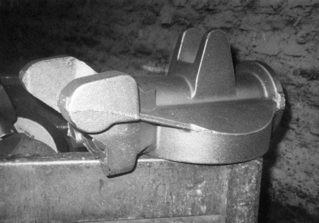
15 2.15 Pressure Control Risering Case Histories ROTOR: Material GGG 40.3; casting weight 26.0 kg; pouring weight 45.6 kg; yield 58%; moulding material, greensand; M S 1.90 cm; modulus A/A = 1.30; modulus B/B = 1.25; f = 0.60; M N 1.14; feeder neck = 45/45 mm; M R = 1.37 cm; feeder = 70 mm dia; pouring temperature 1,400 C min; pouring time 11 sec; gate cross-section 6.5 sq cm; photograph by courtesy of Emmenbrücke foundry, Switzerland. PULLEY WHEEL: Material GGG 40; casting weight 40 kg; pouring weight 65 kg; yield 62%; moulding material, greensand; M S 1.0 cm; modulus A/A = 0.70; f = 0.80; M N 0.80 cm; feeder neck = 32/32 mm; M R = 0.96 cm; feeder = 70 mm dia; pouring time 12 sec; pouring temp. 1,400 C min; gate cross-section 6.0 sq cm; photograph by courtesy of Emmenbrücke foundry, Switzerland. 33


16 34 FRONT WHEEL HUB: Material GGG 40; casting weight: = 11.6 kg; pouring weight: 19 kg; yield: 61%; M S = 1.0 cm; M R = 0.8 cm; feeder = 50 mm dia; x = 4.6 cm; M N = 0.66 cm; feeder neck 40 by 20 mm; pouring temperature 1,370/1,420 C; gate area 2.64 sq cm; sprue area 4.5 sq cm; produced on a Disamatic moulding machine by BFL-Karachi/Pakistan.
; riser ratio 7:1; riser neck M = 0.55 cm. Riser neck 4.5 cm x 1.5 cm; ingates (2) 3.5 cm x 0.5 cm x 12 cm long; runner 3 cm high x 1.")
17 Bottle risering case histories Green sand mould; M S = 0.61 cm; feed metal required 4% x 2.85 kg x 3 = 342 g; riser 14 cm high, 2 cm top diameter. Base 10 cm diameter (increased because of 3 castings per riser); riser ratio 7:1; riser neck M = 0.55 cm. Riser neck 4.5 cm x 1.5 cm; ingates (2) 3.5 cm x 0.5 cm x 12 cm long; runner 3 cm high x 1.5 cm wide; downsprue 2.5 cm diameter x 25 cm high; pouring temperature 1400 C; pouring time 9 sec; photo and data courtesy Bolan Engineering Foundry, Pakistan. 1.3 cm M S 1 cm 20.5 cm HUB PLATE: Ductile Iron grade 420/12; casting weight 2.85 kg; riser weight 2.85 kg; total poured weight 25.3 kg; yield 67.6%. 35
18 CASE HISTORY [ENGLISH SYSTEM (INCH: LB)] Heavy truck wheel hub casting. Weight 150 lb. (68 kg). Very high scrap due to shrinkage defect located at A. (Segment M 3 ) Green sand mould (weak). Significant modulus, M S = 0.77 in. PCR method applies. GATE / RISER SYSTEM Part No: 770 Company: ABC Estimated Casting Weight: 150 lb 1. Layout: 2. Modulus = V CSA M 1 = 2 1 /2 x 1 1 /4 = 0.50 in 6 1 /4 M 2 = 2 1 /2 x 1 3 /4 = 0.87 in 5 M 3 = 1 1 /4 x 2 = 0.77 in 3 1 /4 M S = 0.77 in 3. M N see Card #3 M N = 0.40 in 4. Riser modulus (M R ) M R = M 1 M R = 0.50 in 5. Blind Riser Type Type 2 D 1 = 4.91 x M R (2.46) = 3.0 in* NOTE: Max. M T = M 1 = 0.5 in Assumes good metallurgical quality of the liquid iron. * Use a 3.0 in diameter riser to obtain adequate feed volume. 36
 = 2.4 in 7. Check Feed Volume Estimated Casting weight (each) = 150 lb Estimated Casting volume = 150 0.")
19 6. Riser Contact modulus (M n ) =.40 in See Card #4. 6b. Contact Shape Square Side Length = 4 (M n ) = 1.6 in Round Diameter = 4 (M n ) = 1.6 in Rectangular Short Side = 3 (M n ) = 1.2 in Long Side = 6 (M n ) = 2.4 in 7. Check Feed Volume Estimated Casting weight (each) = 150 lb Estimated Casting volume = = 600 in 3 Required feed volume = 3% of 600 = 18 in 3 Available feed volume X dimension = 4-1/2 in Available feed volume 25 in 3 Number of risers required/casting 1 8. Total choke cross sectional area (section 1.8) per casting. A c = 0.65 in 2 (from chart) Number of gates. n 1 = 1 (per casting) Gate dimensions (4/1): n (4a 2 ) = A c 4a 2 = 0.65 a = 0.4 in 4a= 1.6 in 9. Runner Bar: Cross sectional area, A R = 2 to 4 (A c ) = 3 (2) (0.65) = 3.9 in 2 (2 chokes) Height = 2 x width, 2a 2 = A R = 2 to 4 (A c ) (2) a = 3 (0.65) a = 1.4 in 2a = 2.8 in 10. A S A c H or A c h A S h H A S 2(0.65) 10 3 D 2 S = 4 (2) (0.65) 10/3 π Sprue diam. = 1.74 in or, total choke 0.43 in Pattern Yield: Volume of castings 2 x in 3 risers & contacts 100 sprue & basin 62 runner 50 gates 1 sprue well 10 Total volume poured = 1423 in 3 Pattern Yield = Casting Volume 1200 Total volume poured 1423 = 84% 37
20 2.16 Metallurgical Quality Control and the importance of the nucleation condition One of the most important factors involved in the risering of a casting is to understand and exercise some control over the way in which the solidification process takes place. There is no universally accepted measure of metallurgical quality at the present time. Nevertheless we do have knowledge about the important features of raw materials selection, melting practice, magnesium treatment and inoculation all of which influence metallurgical quality. From a practical view point also it is important to maintain all conditions as constant as possible in order to ensure consistent volume change behaviour with consistent and predictable feed metal requirements Methods to measure the Metallurgical Quality Base Iron: chemistry and wedge test (check undercooling) After treatment and inoculation: chemistry (including Mg content), cooling curve analysis, and nodule count/modulus. (See page 24) Tendency to shrinkage formation Recommended M g content The schematic representation of the volume changes which accompany the cooling and solidification of ductile iron are shown above. As can be seen from the plots A, B, and C the volume changes are not constant, even for ductile irons of identical chemical composition, there can be differences in the degree of nucleation which will affect the volume change pattern. It is the metallurgical quality of the iron which is important and is directly related to the self-feeding characteristics (small volume changes) of the ductile iron. % Mg - residual Less shrinkage problems Modulus (cm) 38
21 2.18 Other Risering Aids The reasons for using exothermic or insulating risers is that you can sometimes use smaller risers where the application dictates that the riser be cold (not gated into such as a top riser and isolated risers). Normal risers use only a small portion (around 14%) of their volume for feed metal. Exothermic and insulating risers can give up to 80% and more as feed metal to the casting. These risers are also designed in relation to the significant modulus of the casting to be fed. In this case you can normally use relatively small risers to feed the castings even in heavy castings. The normal exothermic and insulating risers have, by their nature; an increased effective modulus of about 1.4 to 1.5 times in relation to sand molded riser. Another type of special riser system is called a Mini-Riser which is a small exothermic riser. This type will have an increased modulus of approximately 2.3 times. To calculate the size of the risers, normally you should measure or calculate the significant modulus and casting weight. The actual feed metal required is about 3 5% of metal by weight. This is depending on the mould-hardness, metallurgical quality of the iron and pouring temperature. One should also consult the manufacturer s recommendations on the use of these special types of risers. Maximum utilization of this mini-riser should be no more than 70% of its volume. Example: If we have a casting with a significant modulus of 2.5 cm and a weight of 20 kg you get the following riser: Weight of the riser = 3% minimum x 20 kg = 0.60 kg or 600 gr. 70% = 857 gr. of feed metal would be supplied. The riser modulus should be 1.1 x 2.5 cm = 2.75 cm. The neck is also very important when using these risers. A breaker core is necessary between the casting and the riser. The diameter of the hole in the breaker core should be maximum 1/3 of the diameter of the riser. This has the advantage to avoid shrinkage holes in the riser neck and also it reduces finishing costs. One further advantage of the Mini-Riser is that the pressure, which is created during the growth and expansion of the graphite, is not going on the mould, it is relieved by the riser because there is still liquid metal and a void in the riser. This type of riser was invented in a foundry where they produce hydraulic castings. This foundry has had great problems with penetration and cracking of the cores. After using the Mini-Risers the problem nearly disappeared, because now the feeding system was a pressure control system. During solidification the riser was feeding the castings with liquid iron and during the formation of graphite iron was forced back into the open riser and the pressure was released. All exothermic risers contain aluminum and other elements to provide the reaction. These elements can often cause graphite degeneration. To avoid this problem you have to increase the height or length of the riser neck. There are also other elements that can cause casting defects if they get into the sand system especially in the unburned condition. Defects such as Fish eyes can be produced. 39
22 2.19 The use of chills Since there are more methods of non-destructive testing performed on castings, foundries are forced to find economical ways to make completely sound castings. Ductile Iron has an expansion phase during solidification. If you have a slow solidification and a strong mould you can make sound castings riserless and most often with some chills. However the majority of castings are smaller and made in relatively soft green sand moulds. During the expansion of graphite the mould walls will yield and so it is not possible to use the expansion of the iron for the feeding of the castings. Ductile Iron is also a eutectic alloy. All eutectic alloys are liquid very long during solidification. They don t form a skin during solidification. When using chills we quickly form a solid skin in the area where we have placed the chill. We also increase the density in the matrix producing fine structure in this area. This can help improve wear resistance and pressure tightness. Most foundries are using chills made from Grey iron. The thickness of the chill should be at least the same size as the thickness of the section to be chilled. Adding chills to one side of a section can reduce the modulus by up to 50%. Grey iron chills can be used until they get cracks. Using chills with cracks may produce blow-holes in the area were you placed the chills. To avoid this problem foundries are using more SiC-bricks or graphite blocks as chills. They do not have as strong a chilling tendency as Grey iron chills, but they have no tendency to absorb moisture. Applying chills can reduce the number of risers and normally also the scrap rate. These things can increase yield and reduce finishing costs. RISER t = T Reduce section modulus with chill(s). GATES CHILL Eliminate risers by using chills (minimum modulus > 1 in (25 mm)). T t RAM UP CHILLS 65 mm 40


23 More bottle riser examples Cross section through links and riser. Link castings connected by a bottle riser. LINK CASTING: GGG80; casting weight 5 kg; green sand mould; M S = 1.5 cm; modulus riser neck = 1.05 cm; riser diameter at parting 4 x 1.5 cm + 3 cm = 9 cm; riser height 15 cm (5:1 ratio); feedmetal 741 g (needed 5 kg x 4% x 2 = 400 g); riser neck dimensions 2.5 cm x 6.4 cm. 41


24 4 hub castings - one bottle riser. HUB CASTING: GGG40; one riser for 4 castings; M S = 1.0 cm; casting weight each = 2.5 kg; green sand mould; Mneck = 0.7 cm; neck dimensions 1.8 cm x 6.0 cm; riser modulus 0.8 cm; riser dimensions (5:1 ratio) 3.0 cm top diameter; 15.0 cm high, diameter at parting 14 cm; feedmetal required 400 g; feedmetal supplied 741 g. 42


25 Use of bottle risers. 43
26 BIBLIOGRAPHY 1. Chvorinov, N. Giesserei vol page Wlodawer, R. Directional Solidification of Steel Castings Pergamon Press Karsay, S.I. Ductile Iron vol. 1 Production published by QIT Fer et Titane Inc Karsay, S.I. Ductile Iron vol. 3 Gating and Risering published by QIT Fer et Titane Inc Corlett, G.A. & Anderson, J.V. Experience with an Applied Risering Technique for the Production of Ductile Iron Castings AFS Transactions 90, 1983, Gerhardt Jr., P.C. Computer applications in Gating & Risering System Design for Ductile Iron Castings AFS Transactions 1983, 73, Karsay, S.I. International Foundry Congress, Budapest 1978 paper Karsay, S.I. The practical foundryman s guide to feeding and running Grey, CG and SG iron castings Published by Ferrous Casting Centre Available form AFS Headquarters Des Plaines, U.S.A. 9. Anderson, J.V. & Karsay, S.I. Pouring rate, pouring time and choke design for S.G. Iron Castings. British Foundryman, December Rödter, H. An alternative method of pressure control risering for Ductile Iron castings. QIT Fer et Titane Inc., June 1984 Comments to and criticism of this work are welcome. Please write to: Rio Tinto Iron & Titanium Inc. Technical Services 770 Sherbrooke St. West Suite 1800 Montreal, Quebec H3A 1G1 CANADA September 2000 PRINTED ON RECYCLED AND RECYCLABLE PAPER Copyright Rio Tinto Iron & Titanium inc. PRINTED IN CANADA BY TRANSCONTINENTAL, MÉTROLITHO DIVISION 44
27 CARD #1 ENGLISH Choke Cross Sectional Area in Casting in Cope Casting in Drag ,000 10,000 Total Poured Weight (Incl. Risers) Per Choke. lbs.
28 CARD #1 METRIC Choke Cross Sectional Area cm Casting in Cope Casting in Drag ,000 10,000 Total Poured Weight (Incl. Risers) Per Choke. Kg.
29 CARD #2 ENGLISH 100 Pouring Time Sec ,000 10,000 Total Poured Weight (Incl. Risers) Per Choke. lbs.
30 CARD #2 METRIC Pouring Time Sec ,000 10,000 Total Poured Weight (Incl. Risers) Per Choke. Kg.
31 CARD #3 ENGLISH PRESSURE CONTROL RISERING METHOD 5.0 Significant Modulus (M S ) in Good Quality Poor Quality I II III Riser Neck Modulus (M N ) in Riser Modulus (M R ) in (M R = M N x 1.2)
32 CARD #3 METRIC PRESSURE CONTROL RISERING METHOD 10.0 Significant Modulus (M S ) cm Good Quality Poor Quality I II III Riser Neck Modulus (M N ) cm Riser Modulus (M R ) cm (M R = M N x 1.2)
33 CARD #4 ENGLISH b (in) a (in) USE OF CARD Curved lines represent riser neck modulus (M N ). To find neck dimensions, follow diagonal line to M N (curved line). Where these lines meet read dimensions on a and b scales for neck size.
34 CARD #4 METRIC ,0 6,0 5,0 4,5 4,0 3, ,0 1,8 1,6 2,5 3,0 b (cm) ,2 1,0 0,9 1,4 3 0,7 0,8 2 0,5 0, a (cm) USE OF CARD Curved lines represent riser neck modulus (M N ). To find neck dimensions, follow diagonal line to M N (curved line). Where these lines meet read dimensions on a and b scales for neck size. 9
35 CARD #5 1, x Topmost point of riser Effective feed metal (shaded volume) Topmost point of casting Effective Feed Metal Volume (cm 3 or in. 3 ) x D D (dia) Riser Diameter at Parting (cm or in.) C X D "X" (cm or in.)
APPLIED PRESSURE CONTROL RISERING OF A DUCTILE IRON SAND CASTING. Claudia FLORES, Eudoxio RAMOS, Marco RAMÍREZ and Carlos GONZÁLEZ.
 APPLIED PRESSURE CONTROL RISERING OF A DUCTILE IRON SAND CASTING Claudia FLORES, Eudoxio RAMOS, Marco RAMÍREZ and Carlos GONZÁLEZ. Department of Metallurgical Engineering, Facultad de Química, Universidad
Fundamentals of Casting
 Fundamentals of Casting Chapter 11 11.1 Introduction Products go through a series of processes before they are produced Design Material selection Process selection Manufacture Inspection and evaluation
Computer Design of Feeding Systems for Iron Castings. Or, How to Avoid Years of Problems with 20 Minutes of Analysis
 Computer Design of Feeding Systems for Iron Castings Or, How to Avoid Years of Problems with 20 Minutes of Analysis L E Smiley Finite Solutions Inc, Hamilton, OH D C Schmidt Finite Solutions Inc, Slinger,
Outline CASTING PROCESS - 2. The Mold in Casting. Sand Casting Mold Terms. Assoc Prof Zainal Abidin Ahmad Universiti Teknologi Malaysia
 Outline CASTING PROCESS - 2 Assoc Prof Zainal Abidin Ahmad Universiti Teknologi Malaysia Casting Molds Gating system pouring basin, sprue, runner, gate Riser Core Heating and melting Melting furnaces Pouring
EXPERIMENTAL ANALYSIS OF CYLINDRICAL RISER DESIGN FOR LM6 ALUMINIUM ALLOY CASTINGS
 EXPERIMENTAL ANALYSIS OF CYLINDRICAL RISER DESIGN FOR LM6 ALUMINIUM ALLOY CASTINGS Siva.T 1, Melkin.M.S 2, YugendraRajan.D 3 1,2,3 PG ScholarsDepartment of Mechanical Engineering, James College of Engineering
R.E. Showman, R.C. Aufderheide, N.P. Yeomans
 Advances in Thin-Wall Sand Casting R.E. Showman, R.C. Aufderheide, N.P. Yeomans Ashland Casting Solutions, Dublin, Ohio, USA Abstract Economic and environmental pressures continue to force metalcasters
CALCULATION OF FEEDER SIZE
 Department of Materials and Metallurgical Engineering Bangladesh University of Engineering and Technology, Dhaka MME345 Foundry Engineering Lecture 13: Case Study in Design of Feeding a System 1. CALCULATION
Innovative Simulation of Castings A Technology to Improve Quality of Castings as per Global Specifications with Case Studies
 Innovative Simulation of Castings A Technology to Improve Quality of Castings as per Global Specifications with Case Studies S. K. Paknikar Metallurgical and Foundry Consultant, Pune, E-mail : skpaknikar@gmail.com
Temperature & Density for Castings
 Temperature & Density for Castings FIGURE 5.1 (a) Temperature as a function of time for the solidification of pure metals. Note that freezing takes place at a constant temperature. (b) Density as a function
Feeding Against Gravity with Spot Feeders in High Silicon Ductile Iron
 Feeding Against Gravity with Spot Feeders in High Silicon Ductile Iron N.K. Vedel-Smith 1 and N.S. Tiedje 1 1 Department of Mechanical Engineering, Technical University of Denmark, Kgs. Lyngby, Denmark
An investigation of the effect of five different inoculants on the metal expansion penetration in grey cast iron
 1 An investigation of the effect of five different inoculants on the metal expansion penetration in grey cast iron Izudin Dugic and Ingvar L Svensson Division of Component Technology Jönköping University,
Casting-Comparisons. Mech 423 #2 1
 Casting-Comparisons Mech 423 #2 1 MECH 423 Casting, Welding, Heat Treating and NDT Time: W _ F 14:45-16:00 Credits: 3.5 Session: Fall Introduction Lecture 2 Mech 423 #2 2 Solidification/Freezing Casting
UNIT 45: Riser Design Wizard
 UNIT 45: Riser Design Wizard The Riser Design Wizard allows you to analyze a casting model without risers or feeders, and determine the number, placement and size of risers or feeders that should be attached
Casting Process Part 2
 Mech Zone Casting Process Part 2 (SSC JE Mechanical/ GATE/ONGC/SAIL BHEL/HPCL/IOCL) Sand Casting cope: top half drag: bottom half core: for internal cavities funnel sprue runners gate cavity {risers, vents}
Optimum Design and Analysis of Riser for Sand Casting
 Optimum Design and Analysis of Riser for Sand Casting C. M. Choudhari 1, B. E. Narkhede 1, S. K. Mahajan 2 1 Department of Production Engineering, V.J.T.I., Mumbai, India 2 Director, Technical Education,
The filtration of large grey and ductile iron castings
 The filtration of large grey and ductile iron castings E. Wiese Foseco PLC, UK. Abstract Filtration of mass produced automobile castings is widely and successful applied, less common and more difficult
Feeding Against Gravity with Spot Feeders in High Silicon Ductile Iron
 Feeding Against Gravity with Spot Feeders in High Silicon Ductile Iron N.K. Vedel-Smith 1 and N.S. Tiedje 1 1 Department of Mechanical Engineering, Technical University of Denmark, Kgs. Lyngby, Denmark
Resource Guide. Section 3: Ductile Iron
 Resource Guide Section 3: Ductile Iron Section 3 Ductile Iron Description of Grades... 3-3 65-45-12 Ferritic... 3-4 80-55-06 Partially Pearlitic... 3-6 100-70-02 Pearlitic... 3-8 4512 HRDS Heat Resistant...
STUDY OF PISTON SLEEVE MANUFACTURED BY SAND CASTING PROCESS TO REDUCE REJECTION RATE USING SIMULATION SOFTWARE
 International Journal of Mechanical and Production Engineering Research and Development (IJMPERD) ISSN 2249-6890 Vol. 3, Issue 2, Jun 2013, 161-168 TJPRC Pvt. Ltd. STUDY OF PISTON SLEEVE MANUFACTURED BY
HOT TOPICS Issue # 12, 2005
 HOT TOPICS Issue # 12, 2005 Casting Defect: Doughnut defect 1. Defect code: B118 2. Name: Doughnut or Fisheye defect 3. Description: An annular depression in the casting in the shape of a half a doughnut.
Solidification and Crystallisation 5. Formation of and control of granular structure
 MME 345 Lecture 08 Solidification and Crystallisation 5. Formation of and control of granular structure Ref: [1] A. Ohno, The Solidification of Metals, Chijin Shokan Co. Ltd., 1976 [2] P. Beeley, Foundry
PART II: Metal Casting Processes and Equipment
 Manufacturing Engineering Technology in SI Units, 6 th Edition PART II: Metal Casting Processes and Equipment Introduction Casting involves pouring molten metal into a mold cavity Process produce intricate
Amount of Free Carbon at End of Solidification in Spheroidal Graphite Iron Castings
 Amount of Free Carbon at End of Solidification in Spheroidal Graphite Iron Castings Tomokatsu Kotani 1*, Kazuya Edane 2, Keita Iwakado 3, Haruki Itofuji 4 1* Yanmar Casting Technology Co., Ltd., Matsue
Metal Casting Dr. D. B. Karunakar Department of Mechanical and Industrial Engineering Indian Institute of Technology, Roorkee
 Metal Casting Dr. D. B. Karunakar Department of Mechanical and Industrial Engineering Indian Institute of Technology, Roorkee Module 02 Sand Casting Process Lecture 12 Design Of Risering System-IV Good
Investigation of Shrinkage Defect in Castings by Quantitative Ishikawa Diagram
 A R C H I V E S of F O U N D R Y E N G I N E E R I N G DOI: 10.1515/afe-2017-0032 Published quarterly as the organ of the Foundry Commission of the Polish Academy of Sciences ISSN (2299-2944) Volume 17
Feeding Aids. SQ Group
 Feeding Aids SQ Group Reminder of some principles regarding feeding of castings in foundries. Volume variation during solidification The metal shrinks when cooling down (with the exception of grey iron
COMPARATIVE STUDY OF TENSILE STRENGTH OF DUCTILE IRON ALLOYED WITH AN EQUAL AMOUNT OF COPPER AND NICKEL SEPARATELY
 Journal of Engineering and Science Research 1 (2): 127-132, e-issn: RMP Publications, DOI: COMPARATIVE STUDY OF TENSILE STRENGTH OF DUCTILE IRON ALLOYED WITH AN EQUAL AMOUNT OF COPPER AND NICKEL SEPARATELY
Modeling and Simulation of Solidification in Alloy Steel Sand Castings
 International Journal of Thermal Technologies, Vol.1, No.1 (Dec. 2011) ISSN 2277-4114 Research Article Modeling and Simulation of Solidification in Alloy Steel Sand Castings P. Prabhakara Rao a *, G. Chakraverthi
CASTING SIMULATION OF INSULATOR FOR QUALITY IMPROVEMENT
 CASTING SIMULATION OF INSULATOR FOR QUALITY IMPROVEMENT Dhaval P Chauhan 1, Jaydeep R Shah 2, Alpesh M Patel 3 1 P.G Student, Shri S ad Vidya Mandal Institute of Technology, Bharuch,Gujarat,India 2 Asst.
Ductile Iron for Heavy Section Wind Mill Castings: A European Experience
 Ductile Iron for Heavy Section Wind Mill Castings: A European Experience H. Roedter * and M. Gagné ** Rio Tinto Iron & Titanium Inc. * Frankfurt, Germany, ** Montréal, Canada ABSTRACT During the five year
YIELD IMPROVEMENT CASE STUDY: STACKED SPRING CAPS
 YIELD IMPROVEMENT CASE STUDY: STACKED SPRING CAPS Shouzhu Ou 1, Kent Carlson 1, Malcolm Blair 2, Graham Jones 3, Richard Hardin 1 and Christoph Beckermann 4 1 Research Engineers, Department of Mechanical
Solidification of Metals in Molds
 Metal Casting Solidification of Metals in Molds Pure Metals - Solidify at a constant temperature Planar solidification front Columnar crystals Eutectics - Solidify at a constant temperature Planar solidification
Cast Iron Foundry Practices 3. Metallurgy of grey irons
 MME 345, Lecture 36 Cast Iron Foundry Practices 3. Metallurgy of grey irons Ref: Heine, Loper and Rosenthal. Principles of Metal Casting, Tata McGraw-Hill, 19670 Topics to discuss today 1. Graphite morphology
DESIGN AND ANALYSIS OF RISER FOR SAND CASTING
 DESIGN AND ANALYSIS OF RISER FOR SAND CASTING C. M. Choudhari, Nikhil S. Dalal, Akshay P. Ghude 1, Pratik P. Sankhe, Ashutosh M.Dhotre Mechanical Department, Fr.C.Rodrigues Insitute of Technology, Vashi,
(Full length research article) Modeling and Simulation of Solidification in Alloy Steel Sand Castings
 Modeling and Simulation of Solidification in Alloy Steel Sand Castings") ijesm www.ijesm.com International Journal of Engineering, Science and Metallurgy (Full length research article) Modeling and Simulation of Solidification in Alloy Steel Sand Castings P. Prabhakara Rao
ijesm www.ijesm.com International Journal of Engineering, Science and Metallurgy (Full length research article) Modeling and Simulation of Solidification in Alloy Steel Sand Castings P. Prabhakara Rao
7. Design for Castability
 7. Design for Castability Castability implies ease of producing a casting, minimising cost, defects and lead-time. This is facilitated by high compatibility between product requirements and process capabilities.
Modeling and Simulation of Solidification in Alloy Steel Sand Castings
 International Journal of Thermal Technologies, Vol.1, No.1 (Dec. 2011) ISSN 2277-4114 Research Article Modeling and Simulation of Solidification in Alloy Steel Sand Castings P. Prabhakara Rao a *, G. Chakraverthi
MAKING OF DIE CASTING TOOL
 MAKING OF DIE CASTING TOOL Sivamurugan. K 1, Saravanakumar. R 2, Saravanan. S.T 3 1 Lecturer (S.S), Dept of Mechanical Engineering, VSVN Polytechnic College, Tamilnadu, India 2 Lecturer, Dept of Plastic
Investigations on Design and Thermal Analysis of Apple Type Wind Hub
 Research Article International Journal of Thermal Technologies ISSN 2277-4114 2012 INPRESSCO. All Rights Reserved. Available at http://inpressco.com/category/ijcet Investigations on Design and Thermal
Numerical Simulation for Casting Defect Prediction of Steel Casting -A Case Study
 Numerical Simulation for Casting Defect Prediction of Steel Casting -A Case Study Umesh S. Patil 1, Dr. K. H. Inamdar 2 PG Student, Department of Mechanical Engineering, Walchand College of Engineering,
FILLING SIMULATION OF TILT CASTING DÁNIEL MOLNÁR 1
 Materials Science and Engineering, Volume 42, No. 1 (2017), pp. 94 101. FILLING SIMULATION OF TILT CASTING DÁNIEL MOLNÁR 1 Reliable fluidity data for commercial aluminium foundry alloys are not readily
Steel Castings in Architecture PDH Code: AIA A781 AISC G295
 Steel Castings in Architecture PDH Code: AIA A781 AISC G295 American Institute of Steel Construction E 14a Wednesday 73211 E 14b Friday 62326 Best Practices Credit(s) earned on completion of this course
Yield Improvement of Cast Part Using Computer Aided Casting Simulation
 Yield Improvement of Cast Part Using Computer Aided Casting Simulation Mohamad Riyaz S H 1, Prasad U Raikar 2 1 Student, Product Design and Manufacturing, PG Center VTU, Belagavi, Karnataka 2 Asst. Prorf.,
Effects of Using Fins and Carboceramics on the Solidification Characteristics of Aluminum Casting Alloys
 Materials Sciences and Application, 2011, 2, 891-898 doi:10.4236/msa.2011.27119 Published Online July 2011 (http://www.scirp.org/journal/msa) 891 Effects of Using Fins and Carboceramics on the Solidification
Module - 2 Advanced Metal Casting Processes Lecture - 1 Metal Casting basics, Gating and Risering design
 Advanced Manufacturing Processes Prof. Dr. Apurbba Kumar Sharma Department of Mechanical and Industrial Engineering Indian Institute of Technology, Roorkee Module - 2 Advanced Metal Casting Processes Lecture
Casting Defects - Sand Mold, Metal Casting
 1 de 9 28/11/2013 20:04 About Us Casting Products Casting Workshop Machining Workshop Inspection Certif Casting Defects - Sand Mold, Metal Casting Introducing various metal casting defects with many pictures
Steel Making. Modern Long Product Manufacturing. Process Flow Chart
 Rolling Process Metallurgical Aspects Material Specifications and Chemistries Standard Mill Practices Miscellaneous Tables & Data Elastic Section Modulus Plastic Section Modulus Moment of Inertia SI Conversion
Design of Butterfly Valve Components
 Design of Butterfly Valve Components Ajitha R Nair, Rinson Rajan, Sony C Sunny, Tony Varghese Department Of Mechanical Engineering Musaliar College of Engineering and Technology, Pathanamthitta, Kerala,
DESIGN AND ANALYSIS OF GATING SYSTEM FOR PUMP CASING
 DESIGN AND ANALYSIS OF GATING SYSTEM FOR PUMP CASING N.JAYAKUMAR¹, Dr.S.MOHANAMURUGAN², Dr.R.RAJAVEL³ ¹ Ph.D research scholar, School of Mechanical Engineering, AMET University, Chennai, India ² Professor
Solution of Assignment 5
 Solution of Assignment 5 1. Chills are used in moulds to (a) Achieve directional solidification (b) Reduce possibility of blow holes (c) Increase the freezing time (d) Smoothen the metal for reducing spatter
ME -215 ENGINEERING MATERIALS AND PROCESES
 ME -215 ENGINEERING MATERIALS AND PROCESES Instructor: Office: MEC325, Tel.: 973-642-7455 E-mail: samardzi@njit.edu PROPERTIES OF MATERIALS Chapter 3 Materials Properties STRUCTURE PERFORMANCE PROCESSING
A STUDY ON THERMAL CRACKING OF CAST IRON
 Paper No. 677 A STUDY ON THERMAL CRACKING OF CAST IRON Dr. M. Yousaf Anwar 414 Anwar Pakistan Engineering Congress, 70th Annual Session Proceedings 415 A STUDY ON THERMAL CRACKING OF CAST IRON Dr. M. Yousaf
Metal Casting. Manufacturing Processes for Engineering Materials, 5th ed. Kalpakjian Schmid 2008, Pearson Education ISBN No.
 Metal Casting Important factors in casting Solidification of the metal from its molten state and accompanying shrinkage Flow of the molten metal into the mold cavity Heat transfer during solidification
THE MECHANICAL PROPERTIES OF STAINLESS STEEL
 THE MECHANICAL PROPERTIES OF STAINLESS STEEL Stainless steel is primarily utilised on account of its corrosion resistance. However, the scope of excellent mechanical properties the within the family of
Metals are generally ductile because the structure consists of close-packed layers of
 Chapter 10 Why are metals ductile and ceramics brittle? Metals are generally ductile because the structure consists of close-packed layers of atoms that allow for low energy dislocation movement. Slip
ISSN (Print) Research Article. DOI: /sjet *Corresponding author Titas Nandi
 Research Article. DOI: /sjet *Corresponding author Titas Nandi") DOI: 10.21276/sjet.2016.4.7.4 Scholars Journal of Engineering and Technology (SJET) Sch. J. Eng. Tech., 2016; 4(7):312-324 Scholars Academic and Scientific Publisher (An International Publisher for Academic
DOI: 10.21276/sjet.2016.4.7.4 Scholars Journal of Engineering and Technology (SJET) Sch. J. Eng. Tech., 2016; 4(7):312-324 Scholars Academic and Scientific Publisher (An International Publisher for Academic
SURFACE VEHICLE STANDARD
 SURFACE VEHICLE STANDARD J434 Issued 1956-09 Revised 2004-02 REV. FEB2004 Superseding J434 JUN1986 (R) Automotive Ductile (Nodular) Iron Castings 1. Scope This SAE standard covers the minimum mechanical
The Future and Present of Thermal Analysis of Aluminum
 The Future and Present of Thermal Analysis of Aluminum Yohan Tremblay, Eng. President and Senior Metallurgist Partner and distributors with 65 th AFS Northwest Regional Conference September 29, 2016 Outline
VANADIS 6 SuperClean
 T O O L S T E E L F A C T S SuperClean High performance powder metallurgical cold work tool steel Great Tooling Starts Here! Cover photo: Powder pressing punch of. Excellent results have been obtained
Improving Inoculation in Thin Sectioned Ductile Iron Castings. Marc King Metallurgist Hiler Industries - LaPorte, IN
 Improving Inoculation in Thin Sectioned Ductile Iron Castings Marc King Metallurgist Hiler Industries - LaPorte, IN Introduction: The Kingsbury Castings Division of Hiler Industries has been producing
Casting Defect Analysis using Design of Experiments (DoE) and Computer Aided Casting Simulation Technique
 and Computer Aided Casting Simulation Technique") Available online at www.sciencedirect.com Procedia CIRP 7 (2013 ) 616 621 Forty Sixth CIRP Conference on Manufacturing Systems 2013 Casting Defect Analysis using Design of Experiments (DoE) and Computer
Available online at www.sciencedirect.com Procedia CIRP 7 (2013 ) 616 621 Forty Sixth CIRP Conference on Manufacturing Systems 2013 Casting Defect Analysis using Design of Experiments (DoE) and Computer
One Solution For "Monday Morning" Iron
 One Solution For "Monday Morning" Iron Chad S. Moder Superintendent-Melt and Metal Processing Plant 2 Neenah Foundry Company Monday Morning iron is a phenomenon that every iron casting facility faces.
SECOND SEMESTER DIPLOMA EXAMINATION IN MECHANICAL ENGINEERING- OCTOBER, 2013 MANUFACTURING PROCESS PART-A
 SECOND SEMESTER DIPLOMA EXAMINATION IN MECHANICAL ENGINEERING- OCTOBER, 2013 1. Give any two advantages of ultrasonic inspection test. i. High sensitivity and portability ii. Non hazardous operations MANUFACTURING
Principle No. 3 Design for Optimum Economy Factor #2 Machining cost Factor #1 Strength required Factor #3 Cooling rate
 Principle No. 3 Design for Optimum Economy The price of a casting quoted by the foundry is relatively unimportant both to the ultimate user and to the designer. Instead, the contribution of the casting
Optimization of Riser size of Aluminium alloy (LM6) castings by using conventional method and computer simulation technique
 castings by using conventional method and computer simulation technique") International Journal Of Scientific & Engineering Research, Volume 2, Issue 11, November-2011 1 Optimization of Riser size of Aluminium alloy (LM6) castings by using conventional method and computer simulation
International Journal Of Scientific & Engineering Research, Volume 2, Issue 11, November-2011 1 Optimization of Riser size of Aluminium alloy (LM6) castings by using conventional method and computer simulation
FEEDEX. + + Maximum yield
 COATINGS FILTRATION FEEDING SYSTEMS MELT SHOP REFRACTORIES METALLURGICAL AND POURING CONTROL BINDERS + + Maximum yield FEEDEX HIGH DENSITY exothermic FEEDER SLEEVES + + Smallest footprint + + Minimum fettling
Catalog 2014 Adolf s Foundry Solutions
 Catalog 2014 Adolf s Foundry Solutions by: Adolf s Pattern Shop Alignment Solutions Style ~A~ Alignment Insert Ai-100 1.5 dia. Ai-101 2.0 dia. Ai-102 2.5 dia. Ai-103 2.5 dia. Ai-104 3.5 dia. Style ~A~
DEFECT ANALYSIS OF INLET TUBE CASTING BY COMPUTER SIMULATION VIPUL VASAVA
 International Journal of Mechanical and Production Engineering Research and Development (IJMPERD) ISSN (P): 2249-6890; ISSN (E): 2249-8001 Vol. 7, Issue 3, Jun 2017, 133-146 TJPRC Pvt. Ltd. DEFECT ANALYSIS
TROUBLESHOOTING CRACKS IN STEEL CASTINGS. By Rodman Duncan Casteel Technical Service
 TROUBLESHOOTING CRACKS IN STEEL CASTINGS By Rodman Duncan Casteel Technical Service rod@casteeltec.com 360 468-3588 This presentation is given to the members of Steel Founder s Society of America in order
>> Iron << Aluminum Steel Copper. MeltLab Systems Copyright 2014 All rights reserved 844-Meltlab
 >> Iron
Autonomous Engineering Applied to Investment Casting Process. ICI Conference October 15-18, 2017
 Autonomous Engineering Applied to Investment Casting Process ICI Conference October 15-18, 2017 Overview What is Autonomous Engineering? Traditional simulations vs new approach Case Study #1 Using Autonomous
Investigation on the Rate of Solidification and Mould Heating in the Casting of Commercially Pure Aluminium in Permanent Moulds of varying Thicknesses
 IOSR Journal of Mechanical and Civil Engineering (IOSR-JMCE) e-issn: 2278-1684 Volume 6, Issue 1 (Mar. - Apr. 2013), PP 33-37 Investigation on the Rate of Solidification and Mould Heating in the Casting
Defects caused by air bubbles during casting filling process: A review
 Defects caused by air bubbles during casting filling process: A review Alok Ranjan Pradhan, Sarojrani Pattnaik and Mihir Kumar Sutar* Mechanical Engineering Department, Veer Surendra Sai University of
The Risk of Ductile Iron Post-inoculation for Heavy Section Castings
 ISSN 1392 132 MATERIALS SCIENCE (MEDŽIAGOTYRA). Vol. 9, No. 3. 23 The Risk of Ductile Iron Post-inoculation for Heavy Section Castings Z. Ignaszak Poznan University of Technology, 5 Piotrowo Street, PL-61138
CHILLS 1. INTRODUCTION
 CHILLS 1. INTRODUCTION 2. DEFINITION 3. PURPOSE 4. MATERIAL 5. CALCULATION 6. RULES 7. NON-CONFORMITIES 8. CONCLUSIONS ADDITION : FINS ADDITION : DIFFERENCE IN EFFECT FOR GREY AND DUCTILE IRON 1. INTRODUCTION
Improved ingot casting by using numerical simulation
 Improved ingot casting by using numerical simulation I.Hahn, E.Hepp MAGMA GmbH, Aachen, Germany The ingot casting process is characterized by the progressive solidification of the poured steel from the
HOT TOPICS Issue 2, 2003
 HOT TOPICS Issue 2, 2003 Casting Defect: Surface Defects 1. Defect Code: D 231 -DI-GI-GS (Ductile iron, Gray Iron, in Green Sand) 2. Name: Scab, Expansion Scabbing 3. Description Usually a very rough metallic
Quality of ductile iron
 Quality of ductile iron It is in the eye of the beholder Al Alagarsamy THORS What is quality? Properties? Can we quantify it? Soundness gas and shrinkage Absence of inclusions Absence of carbides chill,
VANADIS 10 SuperClean High performance powder metallurgical cold work tool steel
 SuperClean High performance powder metallurgical cold work tool steel Critical tool steel properties for GOOD TOOL PERFORMANCE Correct hardness for the application Very high wear resistance Sufficient
The Volume Deficit of Iron- Carbon Alloys
 Technical Article 01 ASK Chemicals S. Fischer U. Skerdi S. Hasse The Volume Deficit of Iron- Carbon Alloys The specific volume of the standard casting metals is larger in the liquid state than in the solid
The influence of metallic charge on metallurgical quality and properties of ductile iron
 Kovove Mater. 50 2012 75 82 DOI: 10.4149/km 2012 2 75 75 The influence of metallic charge on metallurgical quality and properties of ductile iron Z. Glavaš* Faculty of Metallurgy, University of Zagreb,
Optimized Design of Risering System for Casted Component by Using Web Based Online Simulation E-Tool
 Volume: 03 Issue: 03 Mar-2016 www.irjet.net p-issn: 2395-0072 Optimized Design of Risering System for Casted Component by Using Web Based Online Simulation E-Tool Bhushan S. Kamble 1, Pradnyesh V. Kadam
Process of Extrusion of Aluminum: Process Overview Billet Dies and Tooling Direct Extrusion Operation Stretching Cutting Aging Packaging
 Process of Extrusion of Aluminum: Process Overview Billet Dies and Tooling Direct Extrusion Operation Stretching Cutting Aging Packaging Process Overview The aluminum extrusion process really begins with
Design Optimization of Feeding System and Solidification Simulation for Cast Iron
 Available online at www.sciencedirect.com ScienceDirect Procedia Technology 14 (2014 ) 357 364 2nd International Conference on Innovations in Automation and Mechatronics Engineering, ICIAME 2014 Design
International Journal of Scientific & Engineering Research, Volume 7, Issue 2, February ISSN
 International Journal of Scientific & Engineering Research, Volume 7, Issue 2, February-2016 434 EFFECT OF WALL THICKNESS AND HEAT TREATMENT VARIABLES ON STRUCTURAL PROPERTIE OF AUSTEMPERED DUCTILE IRONS
EFFECTS OF COOLING MEDIA ON THE MECHANICAL PROPERTIES AND MICROSTRUCTURE OF SAND AND DIE CASTING ALUMINIUM ALLOYS
 EFFECTS OF COOLING MEDIA ON THE MECHANICAL PROPERTIES AND MICROSTRUCTURE OF SAND AND DIE CASTING ALUMINIUM ALLOYS B.O. Adewuyi and J.A. Omotoyinbo Department of Metallurgical and Materials Engineering,
Cast Iron Foundry Practices 1. The family of cast irons
 MME 345, Lecture 34 Cast Iron Foundry Practices 1. The family of cast irons Ref: [1] Heine, Loper and Rosenthal. Principles of Metal Casting, Tata McGraw-Hill, 1967 [2] S H Avner. Introduction to Physical
Available online at ScienceDirect
 Available online at www.sciencedirect.com *.s;@# *," ScienceDirect JOURNAL OF IRON AND STEEL RESEARCH, INTERNATIONAL. 2011, 18(3) : 34-39 Influence of Mold Preheating and Silicon Content on Microstructure
Understanding Contamination From Feeding Aids In Cast Steel
 Understanding Contamination From Feeding Aids In Cast Steel Riser sleeves and hot-toppings can improve the overall quality and cost of steel castings, but they may impact the chemistry of the metal. Tests
Resource Guide. Section 2: Gray Iron
 Resource Guide Section 2: Gray Iron Section 2 Gray Iron Description of Grades... 2-3 G1 Partially Ferritic... 2-4 G1A Ferritic... 2-6 G2 Highly Pearlitic... 2-8 G2A Highly Perlitic High-Strength... 2-10
Some Study on Determination of Riser Sizes for Aluminium Alloy Castings by Using Shape Factor Method
 Some Study on Determination of Riser Sizes for Aluminium Alloy Castings by Using Shape Factor Method T. Nandi 1, S. Koyal 2 and G. Sutradhar 3 1 Associate Professor, Mechanical Engineering Department,
CHAPTER 3 OUTLINE PROPERTIES OF MATERIALS PART 1
 CHAPTER 3 PROPERTIES OF MATERIALS PART 1 30 July 2007 1 OUTLINE 3.1 Mechanical Properties 3.1.1 Definition 3.1.2 Factors Affecting Mechanical Properties 3.1.3 Kinds of Mechanical Properties 3.1.4 Stress
EFFECTS OF INOCULATION ON VARYING WALL THICKNESSES IN GRAY CAST IRON RECYCLING
 1. Saliu Ojo SEIDU, 2. Henry Kayode TALABI, 3. A.S. AKANDE EFFECTS OF INOCULATION ON VARYING WALL THICKNESSES IN GRAY CAST IRON RECYCLING 1-3. Department of Metallurgical and Materials Engineering, Federal
COMPUTER SIMULATION AND EXPERIMENTAL RESEARCH OF CAST PISTON POROSITY
 Tome V (year 2007), Fascicole 2, (ISSN 1584 2665) COMPUTER SIMULATION AND EXPERIMENTAL RESEARCH OF CAST PISTON POROSITY D. KAKAS, L. KOVACEVIC, P. TEREK UNIVERSITY OF NOVI SAD, FACULTY OF TECHNICAL SCIENCES,
Metallurgy - Lecture (2) Solidification
 Solidification") Metallurgy - Lecture (2) Solidification When molten metal enters a mold cavity, its heat is transferred through the mold wall. In the case of pure metals and eutectics, the solidification proceeds layer-bylayer
Metallurgy - Lecture (2) Solidification When molten metal enters a mold cavity, its heat is transferred through the mold wall. In the case of pure metals and eutectics, the solidification proceeds layer-bylayer
Chapter 15 Extrusion and Drawing of Metals
 Introduction Chapter 15 Extrusion and Drawing of Metals Alexandra Schönning, Ph.D. Mechanical Engineering University of North Florida Figures by Manufacturing Engineering and Technology Kalpakijan and
Iron Recalesence By Yohan Tremblay and David Sparkman December 2015
 Executive Summary: This complex arrest in iron tells us about the physical properties our castings will have. It is sensitive to the chemistry and the inoculation of the iron, and can determine if the
Defects analysis, minimize metal wastages and yield improvement for grey cast iron casting: A case study
 Volume 11 Issue 6 ISSN : 0974-7486 Defects analysis, minimize metal wastages and yield improvement for grey cast iron : A case study K.M.Ranasiri 1, A.M.Muzathik 2 * 1 Institute of Technology, University
International Journal of Scientific & Engineering Research, Volume 4, Issue 6, June-2013 ISSN
 1497 Behaviour of Aluminium Alloy Casting with the variation of Pouring Temperature and Permeability of Sand 1 Mahipal Singh, 2Manjinder Bajwa, 3Rohit Sharma, 4Hitesh Arora Abstract: The effect of pouring
Production of a Heavy Section Ductile Iron Grinding Table
 Production of a Heavy Section Ductile Iron Grinding Table Ming You, Xiaogang Diao CITIC Heavy Industries Co., Ltd. Luoyang 471039, China Production process of an extra-large ductile iron grinding table