Structural Steel Welding
|
|
|
- Thomasina Flowers
- 6 years ago
- Views:
Transcription
1 PDH Course S150 Structural Steel Welding Semih Genculu, P.E PDH Online PDH Center 5272 Meadow Estates Drive Fairfax, VA Phone & Fax: An Approved Continuing Education Provider
2 Structural Steel Welding Semih Genculu, P.E. Course Outline This two hour online course discusses the basic factors every engineer should know about structural steel welding. It is important to have an understanding of the potential problems and critical parameters that need to be taken into account in joining steels. This course will enable the designer to become familiar with the typical weld terminology, understand the metallurgical changes that occur during welding, and the precautions to take to avoid situations that can ultimately lead to failures. This course includes a multiple-choice quiz at the end. Learning Objective At the conclusion of this course, the student will: Become familiar with welding terms and symbols, Learn about the various arc welding processes, Understand the source of basic weld defects and remedies, Develop a basic understanding of code requirements and contents of a welding procedure. Course Introduction There are numerous welding processes including arc welding, electron beam welding, friction welding, laser welding, and resistance welding. This course will concentrate on arc welding which is the most common technique used to join structural steels. The factors behind weldability will be discussed and how to avoid common weld defects will be presented. Course Content Arc welding requires striking a low-voltage, high-current arc between an electrode and the workpiece (base metal). The intense heat generated with this arc melts the base metal and allows the joining of two components. The characteristic of the metal that is being welded and the joint type (i.e. groove, fillet, etc.) dictates the welding parameters and the procedure that needs to be followed to obtain a sound weld joint. Semih Genculu Page 2 of 28


3 Typical Arc Welding Processes: Shielded metal arc welding (SMAW): Shielded metal arc welding, which is also known as stick welding, is the most widely used process. The arc is struck between the metal to be welded and a flux coated consumable electrode. The fluxes are mostly made from mineral components and cover the hot weld deposit and protect it from the environment. The solidified glassy product, slag should be removed by chipping or with a wire brush. Gas metal arc welding (GMAW): This process is also referred to as metal inert-gas (MIG) welding uses an uncoated continuous wire. The weld area is shielded from contamination by the gas that is fed through the welding torch. The mode of metal transfer (spray, globular, short-circuiting, pulsed-arc) is varied by adjusting the amperage and the shielding gases used depending on the welding position and the type of joint. For example, the spray transfer mode requires a higher welding current and often a different shielding gas than the globular transfer mode. Most classifications of the GMAW electrodes are based on the chemical composition and the mechanical properties of the weld deposit. Flux-cored arc welding (FCAW): The electrodes for flux cored arc welding consist of a metal sheath surrounding a core of fluxing and/or alloying compounds. The shielding gases and slag are provided by the decomposing flux that is contained within the electrode. Auxiliary shielding is also used in certain instances where deeper penetration is needed. Semih Genculu Page 3 of 28

4 Gas tungsten arc welding (GTAW): Also known as tungsten inert-gas (TIG), the process uses a non-consumable electrode. The shielding gas is again fed through the welding torch. Welding may be accomplished without the addition of filler metal, which is advantageous especially for thin walled parts. Shielding gases: The primary purpose of the shielding gas is to protect the molten weld from contamination and high temperature oxidation by the surrounding atmosphere. Although plain inert gases may not be suitable for all applications, mixtures with reactive gases (i.e. oxygen, nitrogen, hydrogen and carbon dioxide) in controlled quantities will produce stable and relatively spatter-free metal transfer. Argon: Argon by itself is frequently used for MIG welding of nonferrous metals. A mixture of argon and oxygen or argon and carbon dioxide is usually preferred for ferrous metals. The high-density arc that is created by argon permits the energy to go into the work piece as heat resulting in a narrow bead width with deep penetration. Helium: has higher thermal conductivity and arc voltage than argon, which causes it to produce broader weld beads. Because helium is a very light gas, higher flow rates must be used for effective shielding. This characteristic is beneficial in overhead welding. Carbon dioxide: is widely used for steels. Higher welding speed, better joint penetration and sound deposits with good mechanical properties can be achieved. Carbon dioxide is not an inert gas as the argon and helium and breaks down into carbon monoxide and free oxygen under the heat of the arc. The oxygen is used to superheat the weld metal transferring across the arc. Arc welding defects: Most welds contain defects (porosity, cracks, slag inclusions, etc.). The question is to determine if they are significant considering the application. Typically, the applicable codes or standards specify the maximum allowable limits of these types of defects in a weld based on the application. Sometimes discontinuities that may not affect mechanical properties may reduce corrosion performance. The properties of the heat-affected zone (HAZ) are one of the significant factors to consider when evaluating the soundness of the weld joint. The HAZ may be considered as a discontinuity because of the metallurgical alterations as a result of the welding heat, which causes very rapid heating and cooling rates. Grain growth, phase transformations (i.e. brittle untempered martensite which can form depending on the cooling rate and the chemical composition of the base material), formation of precipitates or overaging (loss of strength in precipitation-hardened alloys) all has a drastic effect on the properties of the HAZ. It is possible to improve the weld zone properties by controlling the cooling rate. This may be accomplished by slowing the cooling rate down either by increasing the heat input or preheating (i.e. heating the metal up before welding). Porosity: Gas pockets are formed in the weld metal when they are entrapped during solidification. Molten steel readily absorbs hydrogen, carbon monoxide and other gases to which it is exposed. Since these are not soluble in solid metal, Semih Genculu Page 4 of 28
5 they are expelled as the metal solidifies. Standard shielded arc electrodes with organic coating such as E6010 produce an atmosphere around the arc that contains hydrogen, a notable contributor to porosity. When using such electrodes, welding should be done slowly to allow the gases time to escape since too high of a travel speed causes rapid solidification of the weld metal leading to porosity. Weld joint cleanliness is also crucial in avoiding porosity since moisture, oil, paint, or rust on the base metal may also cause porosity by introducing oxygen or hydrogen into the weld metal. Employing some minimum preheat temperature is often useful to remove condensation. It is also necessary to maintain the fluxes and the coated electrodes dry to avoid moisture pick-up. They are typically kept in an oven at approximately 250ºF, or if the hermetic seal is broken on the containers then the consumables (e.g. welding rods) should be baked at higher temperatures to drive off the moisture and restore the low hydrogen characteristics. Common causes and remedies of porosity are listed below along with a macrograph of a fillet weld containing porosity. An illustration of a groove weld which exhibits cluster porosity is also included with its corresponding radiograph. Porosity: gas pockets or voids that are found in welds Causes Excessive hydrogen, nitrogen or oxygen in welding atmosphere High solidification rate Dirty base metal Dirty filler wire Improper arc length, welding current or electrode manipulation Volatilization of zinc from brass Remedies Use low hydrogen welding process, filler metals high in deoxidizers, increase shielding gas flow Use preheat or increase heat input Clean joint faces and adjacent surfaces Use clean wire and store fillers in a clean area Modify welding parameters and techniques Use copper-silicon filler, reduce heat input Porosity: gas pockets or voids that are found in welds Galvanized Steel Causes Excessive moisture in electrode covering or on joint surfaces High sulfur base metal Remedies Use E7010 electrode and manipulate the arc heat to volatilize the galvanizing (zinc) ahead of the molten weld pool Use recommended procedures for baking and storing electrodes Use electrodes with basic slagging reactions Semih Genculu Page 5 of 28


6 Slag inclusions: This term is used to describe the oxides or other nonmetallic inclusions that become entrapped in the weld metal. They may be caused by contamination or inadequate cleaning between weld passes. The slag derived from fluxes employed during welding needs to be cleaned between weld passes (in multi-pass operations) using a chipping hammer or a wire brush. Slag inclusions are generally linear and may occur either as short particles or as long bands. The macrograph below illustrates a successful multipass weld joint. Semih Genculu Page 6 of 28

7 Tungsten inclusions: In the TIG process, the touching of the electrode to the weld metal may cause transfer of the tungsten particles into the weld metal. These inclusions are detected by x-ray and show up as bright particles since they are much denser than the steel. An example is shown below where the x-ray revealed the tungsten inclusions. Semih Genculu Page 7 of 28

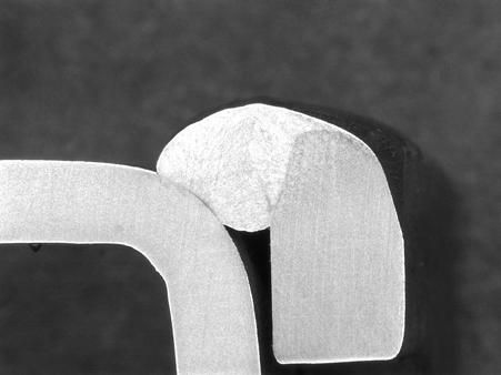
8 Incomplete fusion/penetration: Although these terms are sometimes used interchangeably, lack of fusion occurs when the weld and base metal fail to adequately fuse together. It can also be encountered between weld passes. It may be caused by not raising the temperature of the base metal or previously applied weld metal to the melting point or failure to remove the slag or mill scale. Incomplete fusion is usually elongated in the direction of welding and may have either rounded or sharp edges. Inadequate/lack of penetration is typically due to inadequate heat input for the particular joint that is being welded and is usually seen at the sidewalls of a weld joint, between weld passes or at the root of the weld joint. The shielding gas can also influence the penetration; typically helium is added for nonferrous metals and carbon dioxide is added for ferrous metals (to argon) to increase penetration. The first macrograph below shows an acceptable single pass fillet weld profile with adequate base metal penetration and root fusion. The second macrograph shows lack of penetration to the root in a double welded joint, and the third macrograph illustrates lack of penetration to one of the members. The final illustration shows the sketch of another variation of incomplete root penetration and its appearance on an x-ray film (radiograph). Unsuitable groove design may also result in inadequate joint penetration. Semih Genculu Page 8 of 28


9 Semih Genculu Page 9 of 28

10 Undercut: This occurs when a groove that is formed adjacent to the weld as a result of the melting of the base metal remains unfilled. This groove or sharp recess may vary in depth, width and sharpness at its root. An example is shown in the macrograph below (at the toe of the fillet weld) along with the appearance of this type of defect on a radiograph of a groove weld. Semih Genculu Page 10 of 28


11 Weld profile: The profile of a finished weld may have a considerable effect on the performance under dynamic loading conditions. Overlap, is usually associated with fillet welding but also can occur at the edge of groove welds. The term describes a protrusion of weld metal beyond the bond at the toe of a weld. This condition tends to produce notches that are harmful due to the stress concentration effect. Incorrect welding techniques or currents can cause overlap. Excessive reinforcement or mismatch can also provide stress concentration points where fatigue cracks can initiate. Typical unacceptable butt and fillet weld profiles are shown below along with an example of poor fit-up (mismatch). Semih Genculu Page 11 of 28


12 Macrograph showing poor fit-up (butt weld) Arc strikes: They are caused by the unintentional melting of the base metal outside the weld deposit area by the welding arc. They can also be produced beneath an improperly secured ground connection. The result is a small remelted area that can lead to localized hard or soft spots, cracking or undercut. Another welder-induced defect is weld spatter. It usually occurs when excessive welding current, long arc or welding voltage is used. Below macrograph shows arc strikes near a fillet weld. Semih Genculu Page 12 of 28

13 Cracks: Cracks are the most serious type of weld defects that can lead to catastrophic failures in service. There are many different types of cracks. One way of categorizing them is as surface or subsurface cracks. Another way would be as hot (which occur during or immediately after the weld is made) or cold (cracks that occur after the weld has cooled to room temperature-sometimes within hours or days). In general, weld or heat- affected zone cracks indicate that the weld or the base metal has low ductility and that there is high joint restraint. Many factors can contribute to this condition such as rapid cooling, high alloy composition, insufficient heat input, poor joint preparation, incorrect electrode type, insufficient weld size or lack of preheat. Some common causes and remedies are given in table below. Cracks: Hot and cold cracks or microfissures can form in the weld or the base metal Highly rigid joint Causes Excessive dilution (change in chemical composition of a weld deposit caused by the admixture of the base metal) Poor fit-up Small weld bead High sulfur base metal Excessive distortion Crater cracking (shrinkage cracks which result from sudden stopping of the arc) High residual stresses High hardenability Remedies Preheat Relieve residual stresses mechanically Minimize shrinkage stresses using backstep sequence (a longitudinal sequence in which weld passes are made in the direction opposite to the progress of welding) Change welding current and travel speed Weld with covered electrode negative; butter the joint faces prior to welding (buttering is depositing surfacing metal to provide metallurgically compatible weld metal to the subsequent weld passes) Reduce root opening Increase electrode size, raise welding current, reduce travel speed Use filler metal low in sulfur Change to balanced welding on both sides of joint Fill crater before extinguishing the arc Redesign weldment, change welding sequence, apply intermediate stress relief Preheat, increase heat input, heat treat without cooling to room temperature Photograph illustrating crater cracking resulting from abrupt weld termination Semih Genculu Page 13 of 28
14 in an aluminum weld (MIG process) Preheat: Preheating involves heating the material to be welded either locally or in its entirety, to a specified temperature (preheat temperature), before starting the welding operation. Preheat may also be continued during the welding process in multi-pass weld joints but usually the heat from the welding is sufficient to maintain the desired temperature level. In multi-pass welds the interpass temperature should not be allowed to fall below the preheat temperature. The main reasons for preheat are: 1) to lower the cooling rate in the weld and base metal and avoid formation of hard and brittle phases in the heat affected zone, 2) to allow time for any hydrogen present to diffuse out without causing any cracking by slowing the cooling rate, and 3) to reduce the shrinkage stresses that develop in the joint. Preheat may be applied in various ways depending on the size of the part to be welded. Small assemblies may be heated in a furnace whereas large structures often require heating torches, electrical heating blankets or induction or radiant heaters. Although a high level accuracy is not generally required for preheating carbon steels and it is acceptable to exceed the minimum preheat temperatures by approximately 100 F, quenched and tempered steels demand better controls as overheating may effect their mechanical properties. When heating the joint to be welded, AWS Structural Steel Welding Code (D1.1.) requires that the minimum preheat temperature be established at a distance that is at least equal to the thickness of the thickest member, but not less than 3 inches in all directions from the point of welding. To ensure that the entire weld joint is heated, it is recommended that the surface temperature adjacent to the joint be measured prior to striking the arc. The following factors should be considered in determining whether preheat should be employed; welding code requirements (i.e. AWS, ASME, API, etc.), material thickness, chemical composition of the base materials to be welded, joint restraint, ambient temperature, filler metal hydrogen content. If a certain welding code must be followed then it typically will specify the minimum preheat temperature for a given material, welding process and section thickness. If there is not a code governing the welding, then one has to determine whether it is required. Typically, low carbon steels, such as A36 structural steel, do not require preheat when welding less than 1 inch thick sections. The most critical factor in determining preheat need is discussed in the following section. The effect of carbon equivalent: Generally, the higher the carbon content of a steel, the lower the critical cooling rate and the greater the necessity for preheating and using low hydrogen electrodes. Carbon, however, is not the only element that influences the critical cooling rate. Other elements in the steel are also responsible for the hardening and loss of ductility that occur with rapid cooling. The carbon equivalent (C.E.) may be one of the most significant factors to be considered when determining preheat need and estimating the preheat temperature. The higher the carbon equivalent of a steel, the greater the tendency to form a hard and brittle heat affected zone (HAZ). One of the various empirical formulas used to determine carbon equivalent that represents the sum of the effects of various elements on hardenability is given in the Structural Steel Welding Code (AWS D1.1) as follows: %C.E. = %C + % (Mn+Si)/6+ % (Cr+Mo+V)/5 + % (Ni+Cu)/15 The approximate recommended preheat temperatures based on C.E. are: For up to 0.45% preheat is optional % ºF Over 0.60% ºF Usually a steel that requires preheating must also be kept at this temperature between weld passes. The heat input of the welding process is adequate to maintain the required interpass temperature on most weldments. On massive components this may not be the case and torch heating between passes may be required. Since the purpose of preheating is to reduce the quench rate, the same slow cooling rate must be accomplished for all passes. Semih Genculu Page 14 of 28
15 Besides the widely used carbon equivalent criteria, the following factors should also be considered when determining the need for preheat/post weld heat treat: code requirements, section thickness, restraint, ambient temperature, filler metal hydrogen content and previous cracking problems. Stress Relief (Post Weld Heat Treatment-PWHT): Stress relieving is defined as heating to a suitable temperature (for steel, below the critical transformation temperature), holding long enough at that temperature, and then cooling slowly. PWHT is done to accomplish the following: 1) Reduce residual stresses, 2) Improve the microstructure and fracture toughness of the HAZ, and 3) Remove hydrogen from the welded zone and therefore prevent cracking. Heating and cooling should be done slowly and uniformly to avoid additional stresses to develop in the welded component. In general the greater the difference between the maximum and minimum thickness of the component parts, the slower should be the rate of temperature change. The rates are typically specified in the applicable codes and may be defined as 400 F/hour max. Temperatures may be monitored by thermocouples mounted on the part during the heat treatment. The stress relief range for most carbon steels is F, and the soak time is usually one hour per inch of thickness. Temperature range is higher for alloyed steels. PWHT may have detrimental effects on low alloy steels since they are susceptible to loss of fracture toughness (temper embrittlement) when heated through certain ranges of temperatures. AWS Classifications of Filler Metals: The American Welding Society numbering system tells a lot about the properties and usability of the electrode. Using the stick electrode numbering system as a representative example: The prefix E designates an arc-welding electrode. The first two digits of a four-digit number and the first three digits of a five-digit number indicate tensile strength. For example, E7018 is a 70,000-psi tensile strength electrode while E10018 designates a 100,000-psi one. The next to last digit indicates the position. 1 is for all position, 2 is for flat and horizontal and 3 is for flat, horizontal, vertical down and overhead. The last two digits together indicate the type of electrode coating and the correct polarity to use. An example would be 18 for iron powder, low hydrogen with AC or DC+. E6010: May be used for DC current only is designed for putting the root bead since it develops the most penetrating arc of all. It is an all position electrode. E6011: It is used for all-position AC welding. Its deep and penetrating arc even allows welding on rusty & dirty metal. E6013: All-position, AC electrode used for welding clean sheet metal. It has as oft arc with minimal spatter, moderate penetration and develops an easy-to-clean slag. E7018: A low hydrogen, usually DC, all-position electrode typically used when quality is an issue or for hard to weld metals. It is capable of producing more uniform weld metal with better low temperature impact properties. Weld Symbols: When welds are specified on fabrication drawings a set of symbols are used to describe the type and size of the weld. They can typically be described as a simplified cross section of the actual weld. Some representative symbols are given below. A complete set of symbols is included in a standard published by the American Welding Society. The foundation for constructing a welding symbol is the reference line. The reference line is always shown in the horizontal position, and it should be drawn near the weld joint that it is to identify. The other important elements are the arrow and the symbol which indicates the desired type of weld. All welding information should be shown in accordance with the details illustrated below. Semih Genculu Page 15 of 28
16 Standard Location of Elements of a Welding Symbol Semih Genculu Page 16 of 28
17 Specification of Size and Length of Fillet Welds Semih Genculu Page 17 of 28
18 Applications of Flare-Bevel and Flare-V-Groove Weld Symbol-1 Semih Genculu Page 18 of 28
19 Applications of Flare-Bevel and Flare-V-Groove Weld Symbol-2 Semih Genculu Page 19 of 28
20 Weld Qualifications: Most fabrication documents require qualification of welding procedures and welders. AWS Code D1.1 is the governing document for structural steel welding. A welding procedure specification (WPS) is a formal written instruction that provides the welder with the directions necessary to deposit welds in a consistent manner that meets the project specifications. It includes detail welding conditions for a specific application containing the essential variables that require requalification of procedures when the variables are changed beyond specified limits. Typical weld procedures should, at a minimum, contain information about the base materials that are to be welded, the welding process, the filler metal designation, type of current and range, arc voltage and travel speed, joint design and tolerances, surface preparation, positions of welding, preheat and interpass temperatures, interpass cleaning and post weld heat treat as needed. Each welding document must have a unique identification. The standards do not define a system, it is left up to the manufacturer to devise a suitable system that will meet their needs. The welding positions as illustrated below are also important and are taken into account in certifying welders. Flat (1G/1F), Horizontal (2G/2F), Vertical (3G/3F), Overhead (4G/4F) positions are the most common designations along with 6G (pipe-groove welded in a fixed, 45 degree angle position). Semih Genculu Page 20 of 28
21 Semih Genculu Page 21 of 28
22 Actual welding parameters used to produce an acceptable test joint and the results of the qualification tests (nondestructive, mechanical, chemical and metallurgical as needed per the applicable codes) are documented in a procedure qualification record (PQR). Welding procedures that are qualified by testing must be supported by one or more PQRs. Some joints are considered prequalified according to the American Welding Society Structural Steel Welding Code, D1.1. In order for a WPS to be prequalified, it must comply with all the criteria in AWS D1.1. Therefore it is prudent to thoroughly evaluate the code requirements along with contract documents. Semih Genculu Page 22 of 28
.")


23 Welders are required to take a practical exam to demonstrate their ability to produce sound welds by welding up a plate or a pipe coupon. These samples are then submitted to a test lab for either radiography or mechanical testing to obtain welder performance qualifications (WPQ). Depending on the governing code, nondestructive and/or mechanical tests are performed during qualifications. Typical tests performed for procedure qualifications are tensile testing, bend testing and charpy impact testing. Chemical analysis and hardness testing may also be required when specified. Photograph of a side-bend sample, which failed as a result of lack of fusion Photograph of an acceptable transverse weld tensile specimen that failed in a ductile manner, in the base metal Photograph showing a notched charpy impact specimen ready for testing Semih Genculu Page 23 of 28
24 A sample Welding Procedure (WPS), which was qualified by testing and hence became a weld procedure (PQR), is included along with the accompanying Welder Qualification record (WPQ). Semih Genculu Page 24 of 28
25 Semih Genculu Page 25 of 28
26 Semih Genculu Page 26 of 28
27 Semih Genculu Page 27 of 28
28 Course Summary This course contains detailed information about the various arc-welding processes utilized in welding structural steels. Information about shielding gases is given along with the explanation of the filler metal classification system. Typical weld symbols and unacceptable weld profiles are illustrated. The course describes the sources that are responsible for welding defects and provides solutions on how to avoid them. In addition to the detailed information about weldability, it includes guidelines for following proper procedures in joining materials. Related Links For additional technical information related to this subject, please visit the following websites: aws.org References Welding Handbook by AWS Welding Inspection Technology by AWS Semih Genculu Page 28 of 28
ME E5 - Welding Metallurgy
 ME 328.3 E5 - Welding Metallurgy Purpose: To become more familiar with the welding process and its effects on the material To look at the changes in microstructure and the hardness in the Heat Affected
Introduction to Welding Technology
 Introduction to Welding Technology Welding is a fabrication process used to join materials, usually metals or thermoplastics, together. During welding, the pieces to be joined (the workpieces) are melted
Weld Imperfections and Preventive Measures
 FOURTH EDITION Weld Imperfections and Preventive Measures Published by FOURTH EDITION Weld Imperfections and Preventive Measures Kita-Shinagawa, Shinagawa-Ku, Tokyo, 141-8688 Japan Published by KOBE STEEL,
AN OVERVIEW ON SHIELDED METAL ARC WELDING (SMAW) OF STAINLESS STEEL (SS)
 OF STAINLESS STEEL (SS)") Suggested Spec. for SMAW-SS - 1 - AN OVERVIEW ON SHIELDED METAL ARC WELDING (SMAW) OF STAINLESS STEEL (SS) Scope This document provides information on welding and related operations of stainless steel
Suggested Spec. for SMAW-SS - 1 - AN OVERVIEW ON SHIELDED METAL ARC WELDING (SMAW) OF STAINLESS STEEL (SS) Scope This document provides information on welding and related operations of stainless steel
Manufacturing Process - I Dr. D. K. Dwivedi Department of Mechanical and Industrial Engineering Indian Institute of Technology, Roorkee
 Manufacturing Process - I Dr. D. K. Dwivedi Department of Mechanical and Industrial Engineering Indian Institute of Technology, Roorkee Module - 3 Lecture - 14 Reaction in Weld Region & Welding Defects
NAME 345 Welding Technology Lecture 03 (Welding Joint Design)
") NAME 345 Welding Technology Lecture 03 (Welding Joint Design) Md. Habibur Rahman Lecturer Department of Naval Architecture & Marine Engineering Bangladesh University of Engineering & Technology Dhaka-1000,
NAME 345 Welding Technology Lecture 03 (Welding Joint Design) Md. Habibur Rahman Lecturer Department of Naval Architecture & Marine Engineering Bangladesh University of Engineering & Technology Dhaka-1000,
Welding Defects, Causes and Prevention
 Welding Defects, and In welding the important objective is to obtain sound, defect free weld joint. But it is not always possible to get defect free joint. There will always be some kind of defects in
Structure of Metals 1
 1 Structure of Metals Metals Basic Structure (Review) Property High stiffness, better toughness, good electrical conductivity, good thermal conductivity Why metals have these nice properties - structures
WELDING TECHNOLOGY AND WELDING INSPECTION
 WELDING TECHNOLOGY AND WELDING INSPECTION PRESENTED BY: GOPAL KUMAR CHOUDHARY SVL ENGINEERING SERVICES CHENNAI CONTENTS: DEFINATION TYPES OF WELDING ELECTRODE GEOMETRY EQUIPMENT QUALITY PROCESS SAFETY
Welding Efficiency & Learning Defects (W.E.L.D) Cards A
 Cards A") Welding Efficiency & Learning Defects (W.E.L.D) Cards 1033480-01A Ideal weld path and look for tee and butt joints Definition The proper weld filament, consistent path and fusion. Tee Joint V-Groove Joint
Welding Efficiency & Learning Defects (W.E.L.D) Cards 1033480-01A Ideal weld path and look for tee and butt joints Definition The proper weld filament, consistent path and fusion. Tee Joint V-Groove Joint
WELDING PROCEDURE SPECIFICATION. Shielded Metal Arc Welding-SMAW
 WELDING PROCEDURE SPECIFICATION Shielded Metal Arc Welding-SMAW WPS Number: WPS-SMAW-CS Revision: 0 Company Name & Address ABC WELDING & FABRICATING 123 WeldProc Boulevard Toronto, ON A1B 2C3 CWB Approval
KCWONG. Shielded Metal Arc Welding (SMAW) Gas Metal Arc Welding (GMAW/MIG) Flux-cored Arc Welding (FCAW) Gas Tungsten Arc Welding (GTAW/TIG) KCWONG
 Gas Metal Arc Welding (GMAW/MIG) Flux-cored Arc Welding (FCAW) Gas Tungsten Arc Welding (GTAW/TIG) KCWONG") 1 Shielded Metal Arc Welding (SMAW) Gas Metal Arc Welding (GMAW/MIG) Flux-cored Arc Welding (FCAW) Gas Tungsten Arc Welding (GTAW/TIG) 2 Working Principle Equipment Filler metals Advantages Limitation
1 Shielded Metal Arc Welding (SMAW) Gas Metal Arc Welding (GMAW/MIG) Flux-cored Arc Welding (FCAW) Gas Tungsten Arc Welding (GTAW/TIG) 2 Working Principle Equipment Filler metals Advantages Limitation
Welding. What is Welding?
 Welding Welding What is Welding? Welding is a joining process in which metals are heated, melted and mixed to produce a joint with properties similar to those of the materials being joined. Parent Metal
Lecture 29 DESIGN OF WELDED JOINTS VII
 Lecture 29 DESIGN OF WELDED JOINTS VII This chapter presents the influence of various welding related parameters on fatigue behavior of weld joints. Attempts have been made to explain how (residual stress,
Welding Inspection Defects/Repairs Course Reference WIS 5
 Copy from Welding Inspection Defects/Repairs Course Reference WIS 5 Weld Defects Defects which may be detected by visual inspection can be grouped under five headings Cracks Surface irregularities Contour
INSPECTION OF FIELD WELDING
 INSPECTION OF FIELD WELDING Objective Types of Projects Involving Welding Common Welding Terms & Symbols Welder Qualifications Common Welding Requirements Welding Inspection Types of Projects Involving
Good welding practice Stainless Steels
 Good welding practice Stainless Steels Glenn Allen Welding Engineer TWI North Stainless Steels Four basic types of stainless steels, Austenitic, most common Ferritic Martensitic Duplex, main use oil &
Chapter 12. Flux Cored Arc Welding Equipment, Setup, and Operation Delmar, Cengage Learning
 Chapter 12 Flux Cored Arc Welding Equipment, Setup, and Operation Objectives Explain the FCA welding process Describe what equipment is needed for FCA welding List the advantages of FCA welding, and explain
WELDING CONSIDERATIONS WITH HOT-DIP GALVANIZED STEEL. John du Plessis
 WELDING CONSIDERATIONS WITH HOT-DIP GALVANIZED STEEL John du Plessis ABSTRACT Galvanizing has been in use for hundreds of years. Zinc forms a protective barrier between the steel and the environment. Welding
Materials & Processes in Manufacturing
 2003 Bill Young Materials & Processes in Manufacturing ME 151 Chapter 37 Arc Processes Chapter 38 Resistance Welding Chapter 39 Brazing and Soldering 1 Introduction Arc welding processes produce fusion
GAS METAL ARC WELDING (GMAW)
") GAS METAL ARC WELDING (GMAW) INTRODUCTION Gas Metal Arc Welding (GMAW) is also called Metal Inert Gas (MIG) arc welding. It uses consumable metallic electrode. There are other gas shielded arc welding
GAS METAL ARC WELDING (GMAW) INTRODUCTION Gas Metal Arc Welding (GMAW) is also called Metal Inert Gas (MIG) arc welding. It uses consumable metallic electrode. There are other gas shielded arc welding
71T1 - Gas Shielded Flux Cored Welding Wire Provides excellent performance in all position welding. Weld Metal - Chemistry
 Flux Cored Wire 71T1 - Gas Shielded Flux Cored Welding Wire Provides excellent performance in all position welding Description: Provides a stable arc, low spatter, easy to remove slag, and neat weld metal.
DISCONTINUITIES AND DEFECTS. Training Workbook
 DISCONTINUITIES AND DEFECTS Training Workbook EW-512-4 Written by the Staff of Hobart Institute of Welding Technology Additional copies can be obtained from: Hobart Institute of Welding Technology 400
NAME 345 Welding Technology Lecture 07 Shielded Metal Arc Welding (SMAW)
") NAME 345 Welding Technology Lecture 07 Shielded Metal Arc Welding (SMAW) Md. Habibur Rahman Lecturer Department of Naval Architecture & Marine Engineering Bangladesh University of Engineering & Technology
NAME 345 Welding Technology Lecture 07 Shielded Metal Arc Welding (SMAW) Md. Habibur Rahman Lecturer Department of Naval Architecture & Marine Engineering Bangladesh University of Engineering & Technology
NAME 345 Welding Technology Lecture 12 Welding Defects & Discontinuities
 NAME 345 Welding Technology Lecture 12 Welding Defects & Discontinuities Md. Habibur Rahman Lecturer Department of Naval Architecture & Marine Engineering Bangladesh University of Engineering & Technology
3 TIG welding. 3.1 A description of the method. 3.2 Equipment
 3 TIG welding 3.1 A description of the method TIG welding (also called Gas Tungsten Arc Welding, GTAW) involves striking an arc between a non-consumable tungsten electrode and the workpiece. The weld pool
A Practical Design Guide for Welded Connections Part 1 Basic Concepts and Weld Symbols
 A Practical Design Guide for Welded Connections Part 1 Basic Concepts and Weld Symbols by James Doane, PhD, PE Course Overview This course is divided into 2 parts. Though it provides some basic concepts
1. Poor attitude toward any of the other students, instructors, or judges. 2. Failure to use personal protective equipment (PPE).
.") Welding Contest Rules and Score Sheet 2016 4G Rules: 1. Be Safe & Have Fun 2. Can tack in any position but groove welding must be in accordance with your WPS. 3. Can use wire brush, chipping hammer, and
Welding Contest Rules and Score Sheet 2016 4G Rules: 1. Be Safe & Have Fun 2. Can tack in any position but groove welding must be in accordance with your WPS. 3. Can use wire brush, chipping hammer, and
Manufacturing Process - I Prof. Dr. D.K. Dwivedi Department of Mechanical & Industrial Engineering Indian Institute of Technology, Roorkee
 Manufacturing Process - I Prof. Dr. D.K. Dwivedi Department of Mechanical & Industrial Engineering Indian Institute of Technology, Roorkee Module - 3 Lecture - 11 Tungsten Inert Gas Welding Part 1 Welcome
CIMC: Introduction to Agricultural Power and Technology
 CIMC: Introduction to Agricultural Power and Technology Unit 3- Shielded Metal Arc Welding 1. Shielded Metal Arc Welding also goes by other names. Which of the following is another term for this type of
WELDING Topic and Contents Hours Marks
 Topic and Contents Hours Marks 3.1 Introduction 04 Marks Classification and selection of welding process. Working principle of Gas welding and types of flames. 3.2 Arc welding process 08 Marks Metal arc,
Metallurgical Processes
 Metallurgical Processes Chapter Thirty One: Welding Processes Dr. Eng. Yazan Al-Zain Department of Industrial Engineering 1 Introduction Welding processes divide into two major categories: Fusion Welding:
Technical Data & Welding Guidelines for Ferralium 255SD50 Super Duplex Stainless Steel
 Technical Data & Welding Guidelines for Ferralium 255SD50 Super Duplex Stainless Steel Technical Data & Welding Guidelines FERRALIUM Alloy 255 Ferralium 255SD50 Super Duplex Stainless Steel General FERRALIUM
7.1. WELDING GUIDE Hensley Products
 7.1 WELDING GUIDE Preparation & Welding Process Preparation The Hensley "Welding Guide" is intended to assist customers with welding Hensley G.E.T. products. It is a general welding guide and is not all
pdfmachine trial version
 EFFECT OF WELDING TECHNIQUES (GTAW & SMAW) ON THE MICROSTRUCTURE & MECHANICAL PROPERTIES OF MILD STEEL SA 516 Gr. 70 By Dr. Muhammad Taqi Zahid Butt, S. Ahmed, S. Rasool, U. Ali and S. U. Rehman* ABSTRACT
Heat Input & Interpass temperature during welding
 Heat Input & Interpass temperature during welding By Leif Andersen, One definition of welding goes like this: Welding is control of heat. In the previous article The need for Pre-Heating when Welding we
Common Oxy Fuel Industry Terms
 Common Oxy Fuel Industry Terms A ACETYLENE Gas composed of two parts of carbon and two parts of hydrogen When burned in the atmosphere of oxygen, it produces one of the highest flame temperatures obtainable.
NAME 345 Welding Technology Lecture 09 SAW, ESW & Resistance Welding
 NAME 345 Welding Technology Lecture 09 Md. Habibur Rahman Lecturer Department of Naval Architecture & Marine Engineering Bangladesh University of Engineering & Technology Dhaka-1000, Bangladesh Submerged
Structural Welding Code Reinforcing Steel
 Key Words Allowable stress, inspection, qualification, reinforcing steel, structural details, welded joint details AWS D1.4/D1.4M:2005 An American National Standard Approved by the American National Standards
American Welding Society Nashville Section. Welding Procedure Development
 American Welding Society Nashville Section Welding Procedure Development AWS & ASME Welding Procedures Welding Procedure Specification (WPS) Written document that provides direction to the welder for making
CHAPTER 3: TYPES OF WELDING PROCESS, WELD DEFECTS AND RADIOGRAPHIC IMAGES. Welding is the process of coalescing more than one material part at
 41 CHAPTER 3: TYPES OF WELDING PROCESS, WELD DEFECTS AND RADIOGRAPHIC IMAGES 3.0. INTRODUCTION Welding is the process of coalescing more than one material part at their surface of contact by the suitable
9. Welding Defects 109
 9. Welding Defects 9. Welding Defects 109 Figures 9.1 to 9.4 give a rough survey about the classification of welding defects to DIN 8524. This standard does not classify existing welding defects according
Lecture 23. Chapter 30 Fusion Welding Processes. Introduction. Two pieces are joined together by the application of heat
 Lecture 23 Chapter 30 Fusion Welding Processes Introduction Fusion welding Two pieces are joined together by the application of heat Melting and fusing the interface Filler metal Extra metal added (melted)
Discontinuities and Defects
 Discontinuities and Defects 1 Discontinuity Is An interruption of the typical structure of a material, such as a lack of homogeneity in its mechanical, metallurgical, or physical characteristics. A discontinuity
Weld Quality Standards
 Weld Quality Standards 9/14/2011 1 Index Visual Inspection Criteria Using a Fillet Weld Gage Measuring Weld Reinforcement for a Groove Weld Welding Technique Information Sheets 9/14/2011 2 Visual Inspection
WLD 152 Wire Welding Certification Practice
 WLD 152 Wire Welding Certification Practice Index Course Information Accessing ebook and coursemate info. 3 4 Science on Steel 6-10 Craftsmanship Expectations 11 Welding Projects with Information Sheets
Table of Contents Page No.
 Table of Contents Page No. Personnel... iii Foreword...v List of Tables...xii List of Figures... xiii 1. General Requirements...1 1.1 Scope...1 1.2 Approval...1 1.3 Definitions...1 1.4 Welding Symbols...1
Saggistica Aracne 266
 Saggistica Aracne 266 Moreno Preto Welding Defects Copyright MMXIII ARACNE editrice S.r.l. www.aracneeditrice.it info@aracneeditrice.it via Raffaele Garofalo, 133/A B 00173 Roma (06) 93781065 ISBN 978-88-548-5854-1
Tack Welder Level 3 Question Bank
 Tack Welder Level 3 Question Bank I Fill in the blanks 1. Principle of GAS cutting is 2. Argon cylinder colour is 3. rays will emit from welding arc. 4. Tongs are used to hold 5. Full form of GMAW 6. Diameter
4 Shielded Metal Arc Welding*
 4 Shielded Metal Arc Welding* * Abbreviated MMA (Manual metal arc welding). American designation: shielded metal arc welding (SMAW). Shielded metal arc welding (SMAW) is an AW process that uses a consumable
Guidelines To Gas Metal Arc Welding (GMAW)
") Guidelines To Gas Metal Arc Welding (GMAW) WARNING ARC WELDING can be hazardous. This document contains general information about the topics discussed herein. This document is not an application manual
Guidelines To Gas Metal Arc Welding (GMAW) WARNING ARC WELDING can be hazardous. This document contains general information about the topics discussed herein. This document is not an application manual
ASME B31.3 Process Piping
 ASME B31.3 Process Piping Charles Becht IV, PhD, PE Don Frikken, PE Instructors BECHT ENGINEERING COMPANY, INC. Fabrication and Installation - 1 Piping Development Process 1. Establish applicable system
Defects and Discontinuities. Tim Turner Elizabethtown Technical College
 Defects and Discontinuities Tim Turner Elizabethtown Technical College Defect A flaw or flaws that by nature or accumulated effect render a part or product unable to meet minimum applicable acceptance
Defect. Discontinuity. Defects and Discontinuities. Weld Joint Discontinuities
 Defects and Discontinuities Defect A flaw or flaws that by nature or accumulated effect render a part or product unable to meet minimum applicable acceptance standards or specifications. The term designates
Sub-surface inspection of welds No. 6.03
 Sub-surface inspection of welds Scope This Guidance Note applies to all welds in structural steelwork for bridges. It covers the sub-surface inspection of welds using ultrasonic inspection testing and
Welding Job Knowledge
 Titanium and titanium alloys Weldability of materials Job Titanium and its alloys are chosen because of the following properties: high strength to weight ratio; corrosion resistance; mechanical properties
Fundamentals of Design for Welding. Kelly Bramble 32.1
 Fundamentals of Design for Welding Kelly Bramble 32.1 Fundamentals of Design for Welding Copyright, Engineers Edge, LLC www.engineersedge.com All rights reserved. No part of this training program may be
Planning Advisory Notice
 Planning Advisory Notice Welding Inspection Tasks The Role of the Inspector In the first PAN welding series, we discussed standards, specifications, codes, and responsibilities of those involved in the
Fundamentals of Joining
 Fundamentals of Joining Chapter 30 30.1 Introduction to Consolidation Processes Consolidation Processes consist of Welding Brazing Soldering Fasteners Adhesives Shrink Fits Slots and Tabs Each Process
welder certification welder performance qualification
 Chapter 29 Welder Certification OBJECTIVES After completing this chapter, the student should be able : Explain welder qualification and certification. Outline the steps required certify a welder. Make
EML 2322L -- MAE Design and Manufacturing Laboratory. Welding
 EML 2322L -- MAE Design and Manufacturing Laboratory Welding Intro to Welding A weld is made when separate pieces of material to be joined combine and form one piece when heated to a temperature high enough
Guide to Weldability
 Guide to Weldability Carbon and Low Alloy Steels GUIDE TO WELDABILITY: CARBON and LOW ALLOY STEELS How to get the needed results and stay out of trouble Written by Fritz Saenger, Jr., P.E., IWE This publication
Process Review Checklist
 Process Review Checklist DISCLAIMER. Due to time constraints, the student process review exercise is only a few minutes long. A through, complete process review checklist is not expected as a result but
Planning Advisory Notice
 This Planning Advisory Notice (PAN) is a follow up to the PAN from the March/April issue. In that PAN we discussed some of the codes, standards, and specifications that apply to proper welding design,
Guide to Weldability
 Guide to Weldability Carbon and Low Alloy Steels GUIDE TO WELDABILITY: CARBON and LOW ALLOY STEELS How to get the needed results and stay out of trouble Written by Fritz Saenger, Jr., P.E., IWE This publication
Welding Processes. Consumable Electrode. Non-Consumable Electrode. High Energy Beam. Fusion Welding Processes. SMAW Shielded Metal Arc Welding
 Fusion Consumable Electrode SMAW Shielded Metal Arc Welding GMAW Gas Metal Arc Welding SAW Submerged Arc Welding Non-Consumable Electrode GTAW Gas Tungsten Arc Welding PAW Plasma Arc Welding High Energy
Welding Engineering Prof. Dr. D. K. Dwivedi Department of Mechanical and Industrial Engineering Indian Institute of Technology, Roorkee
 Welding Engineering Prof. Dr. D. K. Dwivedi Department of Mechanical and Industrial Engineering Indian Institute of Technology, Roorkee Module - 4 Arc Welding Processes Lecture - 1 SMAW- 1 So, dear students,
4/19/2018. The heat generated for welding comes from an arc
 Foundations of Agriculture The heat generated for welding comes from an arc Develops when electricity jumps across an air gap between the end of an electrode and the base metal. A. Alternating Current
GMAW (MIG) / FCAW / MCAW
 / FCAW / MCAW") Welding Processes GMAW () / FCAW / MCAW Gas Metal Arc Welding (GMAW), Flux Cored Arc Welding (FCAW) and Metal Cored Arc Welding (MCAW) Gas Metal Arc Welding (GMAW) GMA commonly referred to as Metal Inert
Welding Processes GMAW () / FCAW / MCAW Gas Metal Arc Welding (GMAW), Flux Cored Arc Welding (FCAW) and Metal Cored Arc Welding (MCAW) Gas Metal Arc Welding (GMAW) GMA commonly referred to as Metal Inert
A STUDY OF WELD DEFECTS OF GAS METAL ARC WELDING WITH DIFFERENT SHIELDING GASSES
 A STUDY OF WELD DEFECTS OF GAS METAL ARC WELDING WITH DIFFERENT SHIELDING GASSES Norfadhlina Khalid, Puteri Zirwatul Nadila M. Zamanhuri and Faisal Ahmad Shaiful Baharin Section of Marine Construction
QC Inspection and Qualification Procedure- TX-EDU-VT-1-07, Revision # by Richard J DePue, Supersedes IW-VT-1 Visual Inspection Procedure
 1.0 Scope: QC Inspection and Qualification Procedure- TX-EDU-VT-1-07, Revision #6 03-04-2016 by Richard J DePue, Supersedes IW-VT-1 Visual Inspection Procedure The purpose of this procedure is to define
NATURAL GAS COMPRESSOR STATION PIPELINE WELDING AND RELATED FACILITIES. Engr. Md. Saidur Rahman 1,*
 Proceedings of the International Conference on Mechanical Engineering and Renewable Energy 2015 (ICMERE2015) 26 29 November, 2015, Chittagong, Bangladesh ICMERE2015-PI-243 NATURAL GAS COMPRESSOR STATION
Copyright 1999 Society of Manufacturing Engineers FUNDAMENTAL MANUFACTURING PROCESSES Welding NARRATION (VO):
:") Copyright 1999 Society of Manufacturing Engineers --- 1 --- FUNDAMENTAL MANUFACTURING PROCESSES Welding SCENE 1. CG: Fusion Welding Processes white text centered on black SCENE 2. tape 528, 14:18:33-14:18:52
Copyright 1999 Society of Manufacturing Engineers --- 1 --- FUNDAMENTAL MANUFACTURING PROCESSES Welding SCENE 1. CG: Fusion Welding Processes white text centered on black SCENE 2. tape 528, 14:18:33-14:18:52
Variants of MIG/MAG Flux Cored Arc Welding (FCAW)
") Variants of MIG/MAG Flux Cored Arc Welding (FCAW) Professor Pedro Vilaça * * Contacts Address: P.O. Box 14200, FI-00076 Aalto, Finland Visiting address: Puumiehenkuja 3, Espoo pedro.vilaca@aalto.fi ; Skype:
Variants of MIG/MAG Flux Cored Arc Welding (FCAW) Professor Pedro Vilaça * * Contacts Address: P.O. Box 14200, FI-00076 Aalto, Finland Visiting address: Puumiehenkuja 3, Espoo pedro.vilaca@aalto.fi ; Skype:
Item 448 Structural Field Welding
 Item 448 Structural Field Welding 1. DESCRIPTION 2. MATERIALS Field-weld metal members using the shielded metal arc or flux cored arc welding processes. Provide electrodes for shielded metal arc welding
Lecture 16 Gas Tungsten Arc welding III & Plasma Arc Welding Keyword: 16.1 Selection of pulse parameters
 Lecture 16 Gas Tungsten Arc welding III & Plasma Arc Welding This chapter presents the influence of process parameters of pulse TIG welding process on the development of sound weld joint. Further, the
Productivity Enhancements for GMAW of Titanium Carrie Davis and Michael E. Wells Naval Surface Warfare Center, Carderock Division
 Productivity Enhancements for GMAW of Titanium Carrie Davis and Michael E. Wells Naval Surface Warfare Center, Carderock Division While titanium has been used extensively in seawater cooling systems on
ANSI/AWS D An American National Standard. Structural Welding Code Sheet Steel
 ANSI/AWS D1.3-98 An American National Standard Structural Welding Code Sheet Steel Key Words Sheet steel, allowable stresses, details of welded joints, workmanship qualification, visual acceptance criteria,
Hail University College of Engineering Department of Mechanical Engineering. Joining Processes and Equipment. Fusion-Welding.
 Hail University College of Engineering Department of Mechanical Engineering Joining Processes and Equipment Fusion-Welding Ch 30 Joining is an all-inclusive term covering processes such as welding, brazing,
PILE WELDING QUALITY CONTROL PLAN
 Michigan Department Of Transportation 5627 (10/14) PILE WELDING QUALITY CONTROL PLAN CONTRACTOR LOCATION PREPARED BY CONTROL SECTION JOB NO. DATE Bridge Field Services Approval Block CHECKED BY DATE SPECIFICATIONS
Getting Started with Welding
 Getting Started with Welding With the biochar crew at Living Web Farms Introduction Who we are What we re going to talk about: Basic concepts of working with metals, predominantly steel How to protect
ZIRCALOY WELDING IN OPAL REACTOR REFLECTOR VESSEL
 ZIRCALOY WELDING IN OPAL REACTOR REFLECTOR VESSEL Ortiz L. and Martínez R. INVAP SE, S. C. de Bariloche, Río Negro, Argentina Abstract This paper describes the development of the Zircaloy 4 welding processes
REMOVAL OF CAST LIP STEP 1 STEP 2. Layout cut lines, based on existing welds and verify with dimension taken from new lip. STEP 3
 REMOVAL OF CAST LIP STEP 1 fig. 1-1 Brace clam from cheek plate to cheek plate (A). Brace clam from bucket floor, (just behind back of lip joint), to upper cheek plate on both sides (B). The purpose of
ITEM 448 STRUCTURAL FIELD WELDING
 ITEM 448 STRUCTURAL FIELD WELDING 448.1. Description. This Item shall govern for the field welding of structural steel, reinforcing steel, and miscellaneous steel items as shown on the plans and in accordance
AASHTO/AWS D1.5M/D1.5:2008. Table of Contents
 Table of Contents Personnel...v Foreword...ix List of Tables... xviii List of Figures...xix List of Forms...xxi 1. General Provisions...1 1.1 Application...1 1.2 Base Metal...1 1.3 Welding Processes...1
WELDER S. Visual Inspection HANDBOOK. May 2013
 WELDER S Visual Inspection HANDBOOK May 2013 -- NOTE -- This handbook is NOT intended to serve as a work procedure or to replace any existing procedures. It is solely intended to provide basic information
NAME 345 Welding Technology Lecture 08 Gas Metal Arc Welding (GMAW) Metal Inert Gas (MIG/MUG) Welding
 Metal Inert Gas (MIG/MUG) Welding") NAME 345 Welding Technology Lecture 08 Gas Metal Arc Welding (GMAW) Metal Inert Gas (MIG/MUG) Welding Md. Habibur Rahman Lecturer Department of Naval Architecture & Marine Engineering Bangladesh University
NAME 345 Welding Technology Lecture 08 Gas Metal Arc Welding (GMAW) Metal Inert Gas (MIG/MUG) Welding Md. Habibur Rahman Lecturer Department of Naval Architecture & Marine Engineering Bangladesh University
DOWNLOAD PDF SMAW : BEADS AND FILLET WELDS
 Chapter 1 : SMAW Fillet Welds?!!! - Miller Welding Discussion Forums View Notes - SMAW -beads and fillet weldsterm: Definition: wire brush or grinder used to remove heavy mill scale or corrosion from coupons
Table of Contents Page No.
 Table of Contents Personnel... iii Foreword...v List of Tables... xiii List of Figures...xiv List of Forms...xvi 1. General Provisions...1 1.1 Application...1 1.2 Base Metal...1 1.3 Welding Processes...2
Agenda. Hitsaustekniikka Kon Gas Metal Arc Welding Conventional control (solid wire) - Fundaments
 - Fundaments") Department of Engineering Design and Production Master Degree in Mechanical Engineering Hitsaustekniikka Kon-67.4200 Gas Metal Arc Welding Conventional control (solid wire) - Fundaments Materials Joining
Department of Engineering Design and Production Master Degree in Mechanical Engineering Hitsaustekniikka Kon-67.4200 Gas Metal Arc Welding Conventional control (solid wire) - Fundaments Materials Joining
Porosity The good, the Bad and the Ugly of Radiographic Testing
 19 th World Conference on Non-Destructive Testing 2016 Porosity The good, the Bad and the Ugly of Radiographic Testing Hugo VAUGHAN 1 1 South African Institute of Welding, Johannesburg, South Africa Contact
PIPELINE WELDING PROCEDURE SPECIFICATION
 PIPELINE WELDING PROCEDURE SPECIFICATION Davco Welding Ltd. 1219 3 Avenue Wainwright, Alberta T9W 1K9 WPS No: Scope: DAV-16 This welding procedure specification details the procedure to be followed for
Chapter 4 Gas. Metal Arc Welding
 Chapter 4 Gas Metal Arc What shielding gases or combinations of shielding gases are used in GMAW? Gas Molecular Weight Remarks Carbon 44.010 Reactive shielding gas for ferrous metals providing deep Dioxide
family of stainless steels can be divided into five (5) categories:
 categories:") Welcome to the fifth issue of Tech Talk. This newsletter covers a range of topics on various welding products, applications, metallurgy, techniques, and economics. Previous issues are archived at www.unibraze.com.
Welcome to the fifth issue of Tech Talk. This newsletter covers a range of topics on various welding products, applications, metallurgy, techniques, and economics. Previous issues are archived at www.unibraze.com.
!!!! WARNING!!!! WELDING FUMES AND GASES CAN BE DANGEROUS TO YOUR HEALTH.
 CAREFULLY!!!! WARNING!!!! CAREFULLY WELDING FUMES AND GASES CAN BE DANGEROUS TO YOUR HEALTH. BEFORE USING THIS PRODUCT THE WELDER (END-USER) MUST READ AND UNDERSTAND THE COMPLETE PRODUCT WARNING LABEL
INSPECTION AND TEST. PROCEDURE Total Page 13
 PROCEDURE Total Page 13 Client : Project Name: P/O No. : Item No. : 3 2 1 0 FOR APPROVAL Rev Description Date Prepared By Checked By Approved By PROCEDURE Page 1 of 8 1. General 1.1 Scope This specification