Strain for CMOS performance Improvement
|
|
|
- Lauren Summers
- 6 years ago
- Views:
Transcription
1 IBM Corporation Strain for CMOS performance Improvement +Victor Chan, +Ken Rim, #Meikei Ieong, +Sam Yang, +Rajeev Malik, Young Way Teh, #Min Yang, #Qiqing (Christine) Ouyang +IBM Systems & Technology Group, #IBM Research Division, T. J. Watson Research Center and Chartered Semiconductor Mfg. Ltd IBM Semiconductor Research and Development Center (SRDC) Hopewell Junction, NY 12533
2 Outline * Introduction: Strain helps carriers to travel faster * Substrate-induced strain * Process-induced strain - Contact etch-stop nitride liner (DSL) - Stress Memorization Technique (SMT) - Embedded SiGe in S/D (e-sige) * Stress and Device / Circuit Implication * Mobility Improvement beyond Stress Engineering - Channel Orientation - Substrate Orientation (eg. HOT, DSB) * Summary Fort Collins, Jan 27 Page 2
3 Outline * Introduction: Strain helps carriers to travel faster * Substrate-induced strain * Process-induced strain - Contact etch-stop nitride liner (DSL) - Stress Memorization Technique (SMT) - Embedded SiGe in S/D (e-sige) * Stress and Device / Circuit Implication * Mobility Improvement beyond Stress Engineering - Channel Orientation - Substrate Orientation (eg. HOT) * Summary Fort Collins, Jan 27 Page 3
4 Mechanical Stress: basic A Material A (tens/comp) (eg. Nitride) Material B (eg. Si) Due to material mismatch of A & B from material composition, element size / volume and thermal expansion rate, A will introduce mechanical stress to B. Strained Si Stress transfer Carrier B A Relax Si 1-x Stress transfer Carrier B Fort Collins, Jan 27 Page 4
5 Mechanical Stress : many ways A A Stress transfer Carrier B Stress transfer B Carrier A B Carrier Many different ways Stress transfer dependent on material A deposition / growth condition (eg. process temp, material) subsequent steps (eg. annealing, implantation) gate gate Carrier Carrier source drain source drain Uniaxial stress: 1-direction biaxial stress: 2-directions Fort Collins, Jan 27 Page 5
6 Electrons have higher mobility in Strained (biaxial tensile) Si Ec Ev Eg Conduction Band Unstrained Si <100> <001> Ec fold degenerate conduction valleys <010> fold valleys Biaxial tensile Si in 100 and 010 direction <001> 2 fold valley (lowest E) <100> In Strained Si, i) m* (effective mass) is smaller higher mobility ii) split energy band less inter-valley scattering higher mobility m l m t <010> Larger curvature smaller m* µ = qτ * m K. Rim, VLSI Sym 2002 Fort Collins, Jan 27 Page 6
7 Holes have higher mobility in Strained (biaxial tensile) Si Ec Eg HH HH = heavy holes LH = light holes Valence Band Unstrained Si Ev LH E Spin-orbit m* is rated average of m*(hh) and m*(lh) k 2 fold degenerate valence band (Lower E) Spin-orbit strained Si In Strained Si, i) m* (effective mass) is smaller higher mobility ii) split energy band less carrier scattering higher mobility LH HH in-plane (x,y) E k Out-of-plane (z) K. Rim, VLSI Sym 2002 Fort Collins, Jan 27 Page 7


8 Desired uni-axial stress on CMOS performance gate gate Source Drain Transverse Source Z Drain Longitudinal NMOS PMOS Longitudinal X Tensile Compressive Transverse Y Tensile Tensile Si Depth Z Compressive Tensile Fort Collins, Jan 27 Page 8
9 Longitudinal stress provides different drive current n(100) n(110) nfetion Ioff=100nA/um Ion 100nA/um A B C D E F p(110) p(100) pfet Ion (ua/um) Ion Ioff=100nA/um A B C D E F Compressive Neutral Tensile Fort Collins, Jan 27 Page 9
10 Technology in this presentation IBM 90 / 65nm CMOS technology VCC (V) Lpoly (nm) Tox (nm) Fort Collins, Jan 27 Page 10
11 Outline * Introduction: Strain helps carriers to travel faster * Substrate-induced strain * Process-induced strain - Contact etch-stop nitride liner (DSL) - Stress Memorization Technique (SMT) - Embedded SiGe in S/D (e-sige) * Stress and Device / Circuit Implication * Mobility Improvement beyond Stress Engineering - Channel Orientation - Substrate Orientation (eg. HOT) * Summary Fort Collins, Jan 27 Page 11
12 Strain in Si-based Heterostructures Cubic Lattice at Equilibrium Ge Si 1-x Ge x Si β-sic a a / a x Si Si = x Pseudomorphically Grown Epitaxial Layers Pseudomorphically Grown Epitaxial Layers Strained Strained Si Si 1-x Ge x Relaxed Si Si 1-x Ge x Unstrained Si Tensile-Strained Si on Si 1-x Ge x Compressively Compressive-Strained Si Si 1-x Ge x on Si Fort Collins, Jan 27 Page 12
13 Schematic diagram to show three ways of formation of strained Si MOS devices a) Strained Si/SiGe on bulk wafer b) SiGe-on-Insulator (SGOI) c) Strained-Si Directly On Insulator (SSDOI) MOSFET Strained Si SiGe Si substrate Strained Si SiGe Buried oxide Si substrate Strained Si Buried oxide Si substrate K. Rim, VLSI 2002, B. H. Lee IEDM 2002, K. Rim IEDM 2003 Fort Collins, Jan 27 Page 13
14 Ioff I (A/µm) (na/um) NMOS shows benefits with biaxial tensile strained Si with 13% & 28% Ge Higher NMOS Ion improvement with higher % Ge E E-7 1E E E E-11 Strain Str. Si/SiGe / SiGe (13% (13% [Ge]) Ge) Control nfet NMOS 400.0µ 600.0µ 800.0µ I on (A/µm) Ion (ua/um) 1000 Effective e- Mobility (cm/v-sec) Effective Electron Mobility (cm/v*sec) Str. Si / Relax SiGe 28% Str. Si / Relx. SiGe 28% Str. Si Si / Relx. / Relax SiGe SiGe 13% 13% Str. Si Si / Str. / Str SiGe SiGe 30% 30% / Relx. / Relax SiGe 13% SiGe 13% 110% 200 Control control Mobility Universal Mobility k 1.0M 1.5M % Effective Effective Field, (E E eff (V/cm) eff (MV/um)) K. Rim, VLSI Sym, 2002 Fort Collins, Jan 27 Page 14
15 PMOS shows benefits with Biaxial Tensile Strained Si with 28% Ge pmos Ion only improved with high % Ge in SiGe, eg. > 20%. Ioff (na/um) I (A/µm) off E E E-8 1 1E E-10 pfet PMOS Strain Si / SiGe (28% Ge) Control Strain Str. Si/SiGe / SiGe (28% Ge) [Ge]) Control 200 I (A/µm) Ion (ua/um) 200.0µ 400.0µ K. Rim, VLSI Sym, 2002 Fort Collins, Jan 27 Page 15
16 % Ge vs mobility Mobility Enhancement Factor Strain = (a Str.Si -a Si )/a Si (%) N inv = 1e13 cm -2 Chan.Dop.= 2e17 cm good bad Equivalent [Ge] in Fully Relaxed SiGe (%) nmos (e - ) pmos (h + ) Uniaxial longitudinal tensile stress Biaxial tensile stress Good Good Bad Dependent on %Ge K. Rim, VLSI Sym, 2002 Fort Collins, Jan 27 Page 16
17 Outline * Introduction: Strain helps carriers to travel faster * Substrate-induced strain * Process-induced strain - Contact etch-stop nitride liner (DSL) - Stress Memorization Technique (SMT) - Embedded SiGe in S/D (e-sige) * Stress and Device / Circuit Implication * Mobility Improvement beyond Stress Engineering - Channel Orientation - Substrate Orientation (eg. HOT) * Summary Fort Collins, Jan 27 Page 17
18 Ion enhancement using stress liner compared to neutral liner (non-stressed process) for nmos nmos Ion improves with higher Tensile nitride liner 10-4 a) NMOS Tensile Nit N Ioff (A/µm) Un-stress tensile Ion (µa/µm) H. S. Yang, IEDM 2004 Fort Collins, Jan 27 Page 18
19 Ion enhancement using stress liner compared to neutral liner (non-stressed process) for pmos pmos Ion improves with higher Compressive nitride liner 10-5 b) PMOS Comp Nit P Ioff (A/µm) Un-stress Compressive Ion (µa/µm) H. S. Yang, IEDM 2004 Fort Collins, Jan 27 Page 19


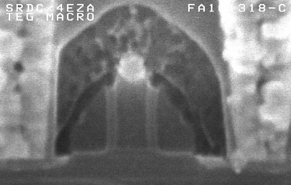
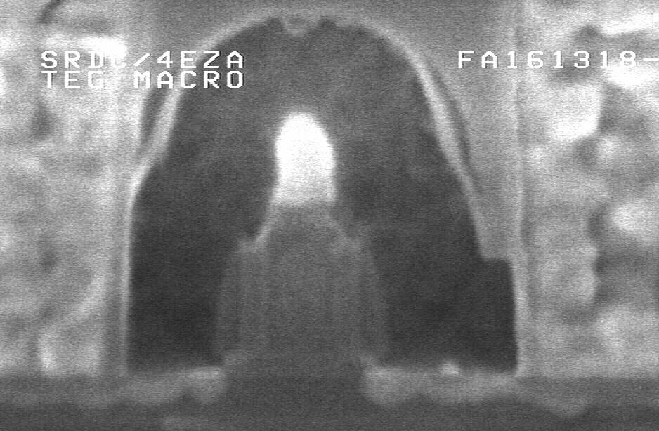
20 SEM cross-section of an SRAM cell features tensile and compressive liner in NMOS and PMOS respectively IBM powerpc TM micro-processor Fmax vs power improves 7 % with DSL due to higher current. Tensile nit Contact Compr nit N P ST oxide Buried tensile Compr N P Fort Collins, Jan 27 H. S. Yang, IEDM 2004 Page 20
21 Nitride film stress changes after annealing Nit film stress tends to be tensile after annealing Annealing temperature will affect hot-carrier reliability nit stress vs anneal temp Tensile annealing Tensile liner A Neutral Performance Reliability Compressive Compressive liner B After nitride Liner deposition After C temperature annealing K. Lim, EESDERC, 2005 Fort Collins, Jan 27 Page 21


22 Nitride film stress will be relaxed after Ge implant Tensile nit Contact Tensile Nit + Ge Compr nit Ge implantation destroys and relaxes nit film N Buried ST oxide P Nit film stress tends to be tensile after annealing Tensile Tensile liner A Neutral Compressive After nitride Liner deposition After Ge implantation Compressive liner B After C annealing H. S. Yang, IEDM 2004 Fort Collins, Jan 27 Page 22
23 Outline * Introduction: Strain helps carriers to travel faster * Substrate-induced strain * Process-induced strain - Contact etch-stop nitride liner (DSL) - Stress Memorization Technique (SMT) - Embedded SiGe in S/D (e-sige) * Stress and Device / Circuit Implication * Mobility Improvement beyond Stress Engineering - Channel Orientation - Substrate Orientation (eg. HOT) * Summary Fort Collins, Jan 27 Page 23

24 Integration process of SMT Amorphous layer by implant After anneal & Nit Removal Stress will be transferred from the nitride film to the channel during annealing. Si is crystallized and stress is memorized Fort Collins, Jan 27 Page 24
25 SMT vs DSL SMT contact end-stop liner Sensitive to Nitride material yes yes (stress, thickness) Require Annealing yes No (dependent on annealing temperature and ramp rate) Sensitive to a-si layer yes some (from extension & S/D implant, dependent on implant species, dose, energy) Sensitive to transistor profile yes yes (eg. gate height, spacer shape and material) Fort Collins, Jan 27 Page 25

 Tensile")


26 SMT annealing Purpose of annealing: i) Tensile transfer from nitride to Si channel through amorphorization layer in S/D, extension and poly gate. ii) a-si crystallization STI from a-si to c-si layer after anneal STI Fort Collins, Jan 27 Page 26
27 NMOS: 15% current improvement with Disposable Tensile Stressor nfet Ioff (na/um) e e e -0 7 Control Tensile Nit stressor 1 1 e -0 8 Tensile contact etch-stop liner is used a b s ( M 1 FN1 0 x p 1 0,0.0 8, M 1 Io n ) nfet Ion (ua/um) Fort Collins, Jan 27 Page 27
28 SMT benefit with different types of Nitiride stressor Stress properties of nitride material is changed after annealing % nmos Ion at target Ioff 115% 110% 105% 100% POR OP_Comp Compr nit No SMT AMAT ~ OP_Nutural Neutral nit BTBAS Nov Tens nit Relative OP Nitride stress liner stress Fort Collins, Jan 27 Page 28
29 Outline * Introduction: Strain helps carriers to travel faster * Substrate-induced strain * Process-induced strain - Contact etch-stop nitride liner (DSL) - Stress Memorization Technique (SMT) - Embedded SiGe in S/D (e-sige) * Stress and Device / Circuit Implication * Mobility Improvement beyond Stress Engineering - Channel Orientation - Substrate Orientation (eg. HOT) * Summary Fort Collins, Jan 27 Page 29


30 PMOS with e-sige structure in S/D Uniaxial stress in Si channel induced by SiGe S/D higher hole mobility to enhance drive current nit Nit liner SiGe SiGe PMOS SiGe SiGe Uniaxial compressive strain Si Substrate C. Ouyang,VLSI Sym, 2005 Fort Collins, Jan 27 Page 30
 2 1 0 blanket patterned C.")
31 SEM photo and SiGe grow rate SiGe epi growth rate in S/D is dependent on pattern density Base on (100) wfr and 15% Ge pmos Strained Si SiGe pmos Strained Si Growth Rate (Angstrom/sec) blanket patterned C. Ouyang,VLSI Sym, 2005 Fort Collins, Jan 27 Page 31
32 PMOS Ion-Ioff for e-sige esige No-eSiGe esige+ Compr nit liner From iedm 05, ibm, Luo Fort Collins, Jan 27 Page 32
33 Outline * Introduction: Strain helps carriers to travel faster * Substrate-induced strain * Process-induced strain - Contact etch-stop nitride liner (DSL) - Stress Memorization Technique (SMT) - Embedded SiGe in S/D (e-sige) * Stress and Device / Circuit Implication * Mobility Improvement beyond Stress Engineering - Channel Orientation - Substrate Orientation (eg. HOT) * Summary Fort Collins, Jan 27 Page 33
34 Ion_N / Ion_P ratio in the Recent Technology Nodes Stress engineering Ion changes Ion_N / Ion_P (beta) ratio may change 2.6 IonN / IonP ratio Tens N, Neut P Tens N, Compr P Neut N, Compr P Neutral N, Neutral P technology node (nm) Fort Collins, Jan 27 Page 34
35 Vt shift due to longitudinal tensile stress Channel Stress can change the energy band gap of Si channel Vtlin (V) Vtlin(V) Vtlin (V) Un-stress control Disposable Stressor Tensile Un-stress control Tensile n POR n OP p POR p OP Disposable Stressor process Without pmos selective RIE Lpoly 0.1 (um) Lgate (um) Lpoly (um) Fort Collins, Jan 27 Page 35


36 Different Active Sizes (along channel) STI provides longitudinal stress and affect N/P Ion. X-direction: more compressive IonN decreases, IonP increases X nmos Ion pmos Ion active size active size Ion changes % Ion change from large from Rx=1.2 to small to 0.24um active size 0 % %Ion All all W=10um Ion changes % Io n from ch an glarge e fro m to R x=1.2 small to 0.24u active m size 25 % %Ion Ion nmos L (um) L_Design (µm) pmos All all W=10umW L (u m ) 1 10 L_Design (µm) V. Chan, IEDM 2003 Fort Collins, Jan 27 Page 36
37 STI Stress Proximity Effect (Different Device Lengths) drive Drive current current change (%) Lgate (µm) active size size PFET pmos NFET nmos n-10x0.045 n-10x0.24 n-10x10 p-10x0.045 p-10x0.24 p-10x active size (symmetric) (um) active size (symmetric) (µm) V. Chan, IEDM 2003 Fort Collins, Jan 27 Page 37
 STI provides both longitudinal")


 % Ion change 24um Ion changes")
 Width (µm) V.")
38 Different Active Sizes with different widths (bi-axial effect) STI provides both longitudinal and lateral stress and affect N/P Ion. X Z Z-direction: more compressive IonN decreases, IonP decreases Ion changes from large to small active size % Ion %Ion % Ion %Ion % Ion change from Rx=1.2 to 0.24um nmos All all L=0.08um L=45nm W (um) width (µm) % Ion change from Rx=1.2 to 0.24um Ion changes from large to small active size pmos all All L=0.08um L=45nm Z W (um) Width (µm) V. Chan, IEDM, 2003 Fort Collins, Jan 27 Page 38
39 STI Stress Proximity Effect (Different Device Widths) drive current change (%) Drive current (%) W(µm) , NFET active size active size pmos PFET nmos n-10x0.045 n-0.24x0.045 n-0.12x0.045 p-10x0.045 p-0.24x0.045 p-0.12x active size (symmetric) (um) active size (symmetric) (µm) V. Chan, IEDM, 2003 Fort Collins, Jan 27 Page 39
40 Technology development & Stress Engineering (1) [Stress engineering is developed early] Base Line Development Pre-manufacturing Develop Strained Si Fabrication Process Modify Device model after mobility enhancement; include STI stress proximity model Mask tape-out (additional mask may be required) Stress Engineering Discovery Circuit Design Circuit adjustment Time Fort Collins, Jan 27 Page 40
41 Technology development & Stress Engineering (2) [Stress engineering is developed a little bit late] Base Line Development Pre-manufacturing Develop Strained Si Fabrication Process (late development) Stress Engineering Discovery Not Modify Device model after mobility enough enhancement; include Time STI stress proximity model Circuit Design Mask tape-out (additional mask may be Required. logic vs array) Not Enough Time Circuit adjustment Time Fort Collins, Jan 27 Page 41
42 Technology development & Stress Engineering (3) [Device adjustment] Stress engineering will change the devices: 1) Ion 2) Vt and Ioff The change will be also dependent on i) Active area dimension (longitudinal and lateral) ii) Device length and width Pre-manufacturing a) Device re-centering b) Additional mask * different circuit region (eg. SRAM array) may have different device centering conditions c) SRAM stability & yield consideration * Device centering to provide good read stability and writibility margin Time Fort Collins, Jan 27 Page 42
43 Technology development & Stress Engineering (4) [Other consideration] i) Extra fabrication process. It may involve : a) substrate preparation; b) nitride deposition process temperature, thickness, stress level, conformity c) extra annealing this may affect dopant activation / d) lithography; e) dry etch / wet etch; f) implantation. deactivation and device reliability (eg hot carrier); ii) Ground rule consideration, especially in the SRAM cell. iii) Critical path and circuit performance. iv) Stress Monitoring by electrical device data and in-line stress monitoring procedure. v) Fabrication process: cycle time, repeatability, uniformity, cost and yield. Fort Collins, Jan 27 Page 43
44 Outline * Introduction: Strain helps carriers to travel faster * Substrate-induced strain * Process-induced strain - Contact etch-stop nitride liner (DSL) - Stress Memorization Technique (SMT) - Embedded SiGe in S/D (e-sige) * Stress and Device / Circuit Implication * Mobility Improvement beyond Stress Engineering - Channel Orientation - Substrate Orientation (eg. HOT) * Summary Fort Collins, Jan 27 Page 44
45 0 vs 45 deg notch X (100) <011> channel Z (001) < 011> channel 0 o notch Y (010) X (100) <001> channel Z (001) <010> channel 45 o notch Y (010) Fort Collins, Jan 27 Page 45
46 <110> (0deg notch) pmos mobility is very sensitive to longitudinal stress sensitive 10-6 pmos Ioff (A/um) Neutral compressive tensile M 1 FP10x_07,0.08,0.10 M 1 Io n pmos Ion (ua/um) Fort Collins, Jan 27 Page 46
47 <100> (45deg notch) pmos mobility is insensitive to longitudinal stress insensitive pmos Ioff (A/um) Neutral tensile compressive pmos Ion (ua/um) Fort Collins, Jan 27 Page 47
48 Both <110> (0 deg) and <100> (45deg notch) nmos mobilities are very sensitive to longitudinal stress 10-6 nmos Ioff (A/um) Ioff (nmos) e-06 e-07 Tensile 45deg 0deg Ion (nmos) 10-9 Neutral compressive tensile Solid = <110> channel Open = <100> channel nmos Ion (ua/um) Fort Collins, Jan 27 Page 48
49 <100> pmos is not sensitive to STI proximity stress 10-7 <100> p-channel pmos Ioff (A/um) Large Rx overhang Small Rx overhang pmos Ion (ua/um) pmos Ioff (A/um) 1e pfet Ioff/W 1e <110> p-channel Large Rx overhang Small Rx overhang 10 1e pfet Ion/W pmos Ion (ua/um) Fort Collins, Jan 27 Page 49
50 Outline * Introduction: Strain helps carriers to travel faster * Substrate-induced strain * Process-induced strain - Contact etch-stop nitride liner (DSL) - Stress Memorization Technique (SMT) - Embedded SiGe in S/D (e-sige) * Stress and Device / Circuit Implication * Mobility Improvement beyond Stress Engineering - Channel Orientation - Substrate Orientation (eg. HOT, DSB) * Summary Fort Collins, Jan 27 Page 50
51 (100) and (110) wafers (100) plane <011> channel (110) plane <110> channel Note: <110> and <001> channel in (110) substrate have different mobility enhancement. Fort Collins, Jan 27 Page 51
 and (110) surfaces to obtain the highest mobility for electrons and holes M. Yang, IEDM 2003, M.")
52 Carrier Mobility Dependence on Surface Orientation Holes Electrons Electron mobility is highest on (100) surface Hole mobility is highest on (110) surface Combine the (100) and (110) surfaces to obtain the highest mobility for electrons and holes M. Yang, IEDM 2003, M. Yang, VLSI 2004 Fort Collins, Jan 27 Page 52
53 CMOS fabrication on Substrates with Hybrid Orientation (1) M. Yang, IEDM 2003, M. Yang, VLSI 2004 Fort Collins, Jan 27 Page 53

54 CMOS fabrication on Substrates with Hybrid Orientation (2) M. Yang, IEDM 2003, M. Yang, VLSI 2004 Fort Collins, Jan 27 Page 54
 SOI pmos on (110) epi-si Key Process Step Selective Epitaxy")
 Si M. Yang, IEDM 2003, M.")
55 CMOS Structure Using HOT Type A Type B pmos on (110) SOI nmos on (100) epi-si nmos on (100) SOI pmos on (110) epi-si Key Process Step Selective Epitaxy layer bonding Type A grow (100) Si in (110) Si Type B grow (110) Si in (100) Si M. Yang, IEDM 2003, M. Yang, VLSI 2004 Fort Collins, Jan 27 Page 55

56 Carrier Mobility Dependence on Surface Orientation PMOS NMOS pmos on (110) surface and nmos on (100) surface Forming hybrid substrate using wafer bonding and Si epitaxy One additional litho level Planar structure, fully compatible with standard CMOS processes M. Yang, IEDM 2003, M. Yang, VLSI 2004 Fort Collins, Jan 27 Page 56
57 Performance of CMOS on Bulk Silicon Substrates pmos pfet Ioff (na/um) e e-06 M1 FP10x_08 M1 Ioff 10 1e e No degradation of Ion by epi-(110). PMOS (100) (110) V dd =1V Compr contact nit liner 1e pfet Ion (ua/um) nmos Ioff (A/um) (110) NMOS (100) Tensile contact nit liner nmos Ion (ua/um) Ioff = 100uA/um Ioff = 10nA/um PMOS Ion +20% +26% NMOS Ion -35% -50% M. Yang, IEDM 2003, M. Yang, VLSI 2004 Fort Collins, Jan 27 Page 57
58 HOT NMOS has same Ion as conventional bulk NMOS and bulk SOI HOT nmos (on BOX) Conventional Bulk NMOS Conventional SOI nmos NMOS Ioff (A/um) Vdd=1V NMOS Ion (ua/um) M. Yang, IEDM 2003, M. Yang, VLSI 2004 Fort Collins, Jan 27 Page 58
59 Carrier mobilities in (100) and (110) substrates are both sensitive to longitudinal stress in channel. Ion change (%) n(100) p(100) A B C D E F Ion change (%) n(110) p(110) A B C D E F Compressive Neutral Tensile Fort Collins, Jan 27 Page 59
60 PMOS on (110) substrate performance is further enhanced by stress engineering Ion = Ioff=100nA/um Fort Collins, Jan 27 Page 60
61 Mobility Enhancement is dependent on device orientation 1000 (100), X,Y (110)-Y (compressive) (110)-X (compres) PMOS Ioff (na/um) (110)-Y (110)-X Solid symbol = X = [110] direction Open symbol = Y = [001] direction X Y PMOS Ion (ua/um) C. D. Sheraw,VLSI 2005 Fort Collins, Jan 27 Page 61
62 Ring Oscillator Delay is improved by higher PMOS Ion with HOT process Quasi Standby Current (A) A n/p=(100) B (HOT) C (HOT+DSL) A B C NMOS (100) SOI Tens liner (100) SOI Tens liner (100) SOI Tens liner PMOS (100) SOI Neutral liner (110) bulk Neutral liner (110) bulk Comp liner Delay (ps/stage) C. D. Sheraw,VLSI 2005 Fort Collins, Jan 27 Page 62
 Ox free interface (100) DSB (n/p = bulk) (110) S T")
 Handle wafer Si (100) Handle wafer Si (100) Step")

63 DSB Direct silicon Bonding N P N HOT (p=bulk, n = SOI) (110) Ox free interface (100) DSB (n/p = bulk) (110) S T I a-si S T I (110) S T I (100) S T I (110) Handle wafer Si (100) Handle wafer Si (100) Handle wafer Si (100) Step 1: (110)/(100) DSB Step 2: selective implant Step 3: SPE & CMOS SPE=solidd phase epitaxy Fort Collins, Jan 27 Page 63
64 pfet performance comparison pfet Ring pfets on DSB shows 35% enhancement compared to (100) Ring oscillator speed is improved by higher pfet Ion in DSB. DSB=direct silicon bonding SPE=soild phase epitaxy Fort Collins, Jan 27 Page 64
65 (100) vs (110) substrates: vector notation (100) substrate X <011> channel Z (001) don t be confused by <110> channel in (100) Substrate and (110) substrate < 011> channel (110) substrate Y (010) X (100) Z (001) Y (010) <001> channel (bad) <110> channel (good) Fort Collins, Jan 27 Page 65
66 0 deg vs 45 deg on (100) wafer: vector notation (100) plane Z,001 Y,010 X, o 45 o <110> 0 o channel, 0 deg notch (100) plane 90 o 45 o <100> 0 o channel, 45 deg notch Fort Collins, Jan 27 Page 66
67 Outline * Introduction: Strain helps carriers to travel faster * Substrate-induced strain * Process-induced strain - Contact etch-stop nitride liner (DSL) - Stress Memorization Technique (SMT) - Embedded SiGe in S/D (e-sige) * Stress and Device / Circuit Implication * Mobility Improvement beyond Stress Engineering - Channel Orientation - Substrate Orientation (eg. HOT) * Summary Fort Collins, Jan 27 Page 67
68 Summary NMOS PMOS Disadvantage & limitation Biaxial Tensile Strain Extra cost on substrate, difficulty in substrate preparation, integration, & device design. Contact etch-stop liner (DSL) Extra steps in integration, ground rule considera tion SMT o Extra steps in integration e-sige o High process complexity, difficulty in epigrowth, yield Substrate Orientation (HOT, DSB) o Extra Cost on hybrid substrate, extra steps eg. Epi to prepare isolation Channel Orientation (<100>, 45deg) o No further improvement in PMOS current Fort Collins, Jan 27 Page 68
, ASTA alliance (IBM, AMD, Sony, Toshiba) Fort Collins, Jan 27 Page")
69 Acknowledgement IBM SRDC System and Technology Group, IBM Yorktown Research, ICIS alliance (IBM, Chartered, Infineon, Samsung), ASTA alliance (IBM, AMD, Sony, Toshiba) Fort Collins, Jan 27 Page 69
Strain Engineering for Performance Enhancement in Advanced Nano Scaled SOI-MOSFETs
 Strain Engineering for Performance Enhancement in Advanced Nano Scaled SOI-MOSFETs S. Flachowsky a), R. Illgen a), T. Herrmann a), A. Wei b), J. Höntschel b), M. Horstmann b), W. Klix a), and R. Stenzel
Performance Predictions for Scaled Process-induced Strained-Si CMOS
 Performance Predictions for Scaled Process-induced Strained-Si CMOS G Ranganayakulu and C K Maiti Department of Electronics and ECE, IIT Kharagpur, Kharagpur 721302, India Abstract: Device and circuit
Tri-Gate Transistor Architecture with High-k Gate Dielectrics, Metal Gates and Strain Engineering
 Tri-Gate Transistor Architecture with High-k Gate Dielectrics, Metal Gates and Strain Engineering Jack Kavalieros, Brian Doyle, Suman Datta, Gilbert Dewey, Mark Doczy, Ben Jin, Dan Lionberger, Matthew
6.774 Fall 2006: Global and Local Stress to Enhance CMOS Performance
 6.774 Fall 2006: Global and Local Stress to Enhance CMOS Performance techniques have been developed to strain the Si in the MOSFET channel, in order to enhance carrier mobility and current drive some of
High Performance High-K + Metal Gate Strain Enhanced Transistors on (110) Silicon
 Silicon") High Performance High-K + Metal Gate Strain Enhanced Transistors on (110) Silicon Paul Packan, S. Cea*, H. Deshpande, T. Ghani, M. Giles*, O. Golonzka, M. Hattendorf, R. Kotlyar*, K. Kuhn, A. Murthy, P.
High Performance High-K + Metal Gate Strain Enhanced Transistors on (110) Silicon Paul Packan, S. Cea*, H. Deshpande, T. Ghani, M. Giles*, O. Golonzka, M. Hattendorf, R. Kotlyar*, K. Kuhn, A. Murthy, P.
Strained Silicon-On-Insulator Fabrication and Characterization
 10.1149/1.2728880, The Electrochemical Society Strained Silicon-On-Insulator Fabrication and Characterization M. Reiche a, C. Himcinschi a, U. Gösele a, S. Christiansen a, S. Mantl b, D. Buca b, Q.T. Zhao
Complementary Metal Oxide Semiconductor (CMOS)
") Technische Universität Graz Institute of Solid State Physics Complementary Metal Oxide Semiconductor (CMOS) Franssila: Chapters 26,28 Technische Universität Graz Institute of Solid State Physics Complementary
Technische Universität Graz Institute of Solid State Physics Complementary Metal Oxide Semiconductor (CMOS) Franssila: Chapters 26,28 Technische Universität Graz Institute of Solid State Physics Complementary
Chapter 2 Manufacturing Process
 Digital Integrated Circuits A Design Perspective Chapter 2 Manufacturing Process 1 CMOS Process 2 CMOS Process (n-well) Both NMOS and PMOS must be built in the same silicon material. PMOS in n-well NMOS
Isolation Technology. Dr. Lynn Fuller
 ROCHESTER INSTITUTE OF TECHNOLOGY MICROELECTRONIC ENGINEERING Isolation Technology Dr. Lynn Fuller Motorola Professor 82 Lomb Memorial Drive Rochester, NY 14623-5604 Tel (585) 475-2035 Fax (585) 475-5041
CMOS Technology. Flow varies with process types & company. Start with substrate selection. N-Well CMOS Twin-Well CMOS STI
 CMOS Technology Flow varies with process types & company N-Well CMOS Twin-Well CMOS STI Start with substrate selection Type: n or p Doping level, resistivity Orientation, 100, or 101, etc Other parameters
EE 143 FINAL EXAM NAME C. Nguyen May 10, Signature:
 INSTRUCTIONS Read all of the instructions and all of the questions before beginning the exam. There are 5 problems on this Final Exam, totaling 143 points. The tentative credit for each part is given to
Lecture 0: Introduction
 Lecture 0: Introduction Introduction Integrated circuits: many transistors on one chip. Very Large Scale Integration (VLSI): bucketloads! Complementary Metal Oxide Semiconductor Fast, cheap, low power
Czochralski Crystal Growth
 Czochralski Crystal Growth Crystal Pulling Crystal Ingots Shaping and Polishing 300 mm wafer 1 2 Advantage of larger diameter wafers Wafer area larger Chip area larger 3 4 Large-Diameter Wafer Handling
Problem 1 Lab Questions ( 20 points total)
") Problem 1 Lab Questions ( 20 points total) (a) (3 points ) In our EE143 lab, we use Phosphorus for the source and drain diffusion. However, most advanced processes use Arsenic. What is the advantage of
Problem 1 Lab Questions ( 20 points total) (a) (3 points ) In our EE143 lab, we use Phosphorus for the source and drain diffusion. However, most advanced processes use Arsenic. What is the advantage of
Process Integration. MEMS Release Techniques Sacrificial Layer Removal Substrate Undercut
 Process Integration Self-aligned Techniques LOCOS- self-aligned channel stop Self-aligned Source/Drain Lightly Doped Drain (LDD) Self-aligned silicide (SALICIDE) Self-aligned oxide gap MEMS Release Techniques
Characterization and Fabrication of 90nm Strained Silicon PMOS using TCAD
 Characterization and Fabrication of 90nm Strained Silicon PMOS using TCAD M. A. Abd Hamid and F. Sulaiman, Member, IEEE Abstract The paper focuses on the enhancement of conventional 90nm PMOS using graded
VLSI Systems and Computer Architecture Lab
 ΚΥΚΛΩΜΑΤΑ VLSI Πανεπιστήμιο Ιωαννίνων CMOS Technology Τμήμα Μηχανικών Η/Υ και Πληροφορικής 1 From the book: An Introduction ti to VLSI Process By: W. Maly ΚΥΚΛΩΜΑΤΑ VLSI Διάρθρωση 1. N well CMOS 2. Active
9/4/2008 GMU, ECE 680 Physical VLSI Design
 ECE680: Physical VLSI Design Chapter II CMOS Manufacturing Process 1 Dual-Well Trench-Isolated CMOS Process gate-oxide TiSi 2 AlCu Tungsten SiO 2 p-well poly n-well SiO 2 n+ p-epi p+ p+ 2 Schematic Layout
Layout-related stress effects on TID-induced leakage current
 Layout-related stress effects on TID-induced leakage current Nadia Rezzak, R. D. Schrimpf, M. L. Alles, En Xia Zhang, Daniel M. Fleetwood, Yanfeng Albert Li Radiation Effects Group Vanderbilt University,
Process Integration. NMOS Generic NMOS Process Flow. CMOS - The MOSIS Process Flow
 Process Integration Self-aligned Techniques LOCOS- self-aligned channel stop Self-aligned Source/Drain Lightly Doped Drain (LDD) Self-aligned silicide (SALICIDE) Self-aligned oxide gap MEMS Release Techniques
CMOS VLSI Design. Introduction. All materials are from the textbook Weste and Harris, 3 rd Edition CMOS VLSI DESIGN. Introduction
 CMOS VLSI Design Introduction ll materials are from the textbook Weste and Harris, 3 rd Edition CMOS VLSI DESIGN Introduction Chapter previews the entire field, subsequent chapters elaborate on specific
VLSI. Lecture 1. Jaeyong Chung System-on-Chips (SoC) Laboratory Incheon National University. Based on slides of David Money Harris
 Laboratory Incheon National University. Based on slides of David Money Harris") VLSI Lecture 1 Jaeyong Chung System-on-Chips (SoC) Laboratory Incheon National University Based on slides of David Money Harris Goals of This Course Learn the principles of VLSI design Learn to design
VLSI Lecture 1 Jaeyong Chung System-on-Chips (SoC) Laboratory Incheon National University Based on slides of David Money Harris Goals of This Course Learn the principles of VLSI design Learn to design
VLSI Design and Simulation
 VLSI Design and Simulation CMOS Processing Technology Topics CMOS Processing Technology Semiconductor Processing How do we make a transistor? Fabrication Process Wafer Processing Silicon single crystal
Chapter 2 Problems. The CMOS technology we need to realize is shown below, from Figure 1-34 in the text. S P + N P + N WELL P +
 Chapter 2 roblems 2.1 Sketch a process flow that would result in the structure shown in Figure 1-34 by drawing a series of drawings similar to those in this chapter. You only need to describe the flow
VLSI INTRODUCTION P.VIDYA SAGAR ( ASSOCIATE PROFESSOR) Department of Electronics and Communication Engineering, VBIT
 Department of Electronics and Communication Engineering, VBIT") VLSI INTRODUCTION P.VIDYA SAGAR ( ASSOCIATE PROFESSOR) contents UNIT I INTRODUCTION: Introduction to IC Technology MOS, PMOS, NMOS, CMOS & BiCMOS technologies. BASIC ELECTRICAL PROPERTIES : Basic Electrical
VLSI INTRODUCTION P.VIDYA SAGAR ( ASSOCIATE PROFESSOR) contents UNIT I INTRODUCTION: Introduction to IC Technology MOS, PMOS, NMOS, CMOS & BiCMOS technologies. BASIC ELECTRICAL PROPERTIES : Basic Electrical
Contact Resistance Reduction using Advanced Implant and Anneal Techniques for 7nm Node and Beyond
 Contact Resistance Reduction using Advanced Implant and Anneal Techniques for 7nm Node and Beyond Fareen Adeni Khaja Global Product Manager, Front End Products Transistor and Interconnect Group NCCAVS
Introduction to CMOS VLSI Design. Layout, Fabrication, and Elementary Logic Design
 Introduction to CMOS VLSI Design Layout, Fabrication, and Elementary Logic Design CMOS Fabrication CMOS transistors are fabricated on silicon wafer Lithography process similar to printing press On each
A Novel Low Temperature Self-Aligned Field Induced Drain Polycrystalline Silicon Thin Film Transistor by Using Selective Side-Etching Process
 Chapter 3 A Novel Low Temperature Self-Aligned Field Induced Drain Polycrystalline Silicon Thin Film Transistor by Using Selective Side-Etching Process 3.1 Introduction Low-temperature poly-si (LTPS) TFTs
PROCESS FLOW AN INSIGHT INTO CMOS FABRICATION PROCESS
 Contents: VI Sem ECE 06EC63: Analog and Mixed Mode VLSI Design PROCESS FLOW AN INSIGHT INTO CMOS FABRICATION PROCESS 1. Introduction 2. CMOS Fabrication 3. Simplified View of Fabrication Process 3.1 Alternative
VLSI Technology Dr. Nandita Dasgupta Department of Electrical Engineering Indian Institute of Technology, Madras
 VLSI Technology Dr. Nandita Dasgupta Department of Electrical Engineering Indian Institute of Technology, Madras Lecture - 36 MOSFET I Metal gate vs self-aligned poly gate So far, we have discussed about
We are moving to 155 Donner Lab From Thursday, Feb 2 We will be able to accommodate everyone!
 -Spring 006 Digital Integrated Circuits Lecture 4 CMOS Manufacturing Process Design Rules EECS141 1 Good News! We are moving to 155 Donner Lab From Thursday, Feb We will be able to accommodate everyone!
EE 330 Lecture 9. IC Fabrication Technology Part 2
 EE 330 Lecture 9 IC Fabrication Technology Part 2 Quiz 8 A 2m silicon crystal is cut into wafers using a wire saw. If the wire diameter is 220um and the wafer thickness is 350um, how many wafers will this
Chapter 3 CMOS processing technology
 Chapter 3 CMOS processing technology (How to make a CMOS?) Si + impurity acceptors(p-type) donors (n-type) p-type + n-type => pn junction (I-V) 3.1.1 (Wafer) Wafer = A disk of silicon (0.25 mm - 1 mm thick),
Complementary Metal-Oxide-Semiconductor Very Large-Scale Integrated Circuit Design
 Complementary Metal-Oxide-Semiconductor Very Large-Scale Integrated Circuit Design Bradley A. Minch Mixed Analog-Digital VLSI Circuits and Systems Lab Cornell University Ithaca, NY 14853 5401 minch@ece.cornell.edu
EE 330 Lecture 9. IC Fabrication Technology Part II. -Oxidation -Epitaxy -Polysilicon -Planarization -Resistance and Capacitance in Interconnects
 EE 330 Lecture 9 IC Fabrication Technology Part II -Oxidation -Epitaxy -Polysilicon -Planarization -Resistance and Capacitance in Interconnects Review from Last Time IC Fabrication Technology Crystal Preparation
Progress in Monolithic III-V/Si and towards processing III-V Devices in Silicon Manufacturing. E.A. (Gene) Fitzgerald
 Fitzgerald") Progress in Monolithic III-V/Si and towards processing III-V Devices in Silicon Manufacturing E.A. (Gene) Fitzgerald M.J. Mori, C.L.Dohrman, K. Chilukuri MIT Cambridge, MA USA Funding: MARCO IFC and Army
Progress in Monolithic III-V/Si and towards processing III-V Devices in Silicon Manufacturing E.A. (Gene) Fitzgerald M.J. Mori, C.L.Dohrman, K. Chilukuri MIT Cambridge, MA USA Funding: MARCO IFC and Army
Fairchild Semiconductor Application Note June 1983 Revised March 2003
 Fairchild Semiconductor Application Note June 1983 Revised March 2003 High-Speed CMOS (MM74HC) Processing The MM74HC logic family achieves its high speed by utilizing microcmos Technology. This is a 3.5
Microelectronics. Integrated circuits. Introduction to the IC technology M.Rencz 11 September, Expected decrease in line width
 Microelectronics Introduction to the IC technology M.Rencz 11 September, 2002 9/16/02 1/37 Integrated circuits Development is controlled by the roadmaps. Self-fulfilling predictions for the tendencies
EE40 Lec 22. IC Fabrication Technology. Prof. Nathan Cheung 11/19/2009
 Suggested Reading EE40 Lec 22 IC Fabrication Technology Prof. Nathan Cheung 11/19/2009 300mm Fab Tour http://www-03.ibm.com/technology/manufacturing/technology_tour_300mm_foundry.html Overview of IC Technology
Chapter 4 : ULSI Process Integration (0.18 m CMOS Process)
") Chapter : ULSI Process Integration (0.8 m CMOS Process) Reference. Semiconductor Manufacturing Technology : Michael Quirk and Julian Serda (00). - (00). Semiconductor Physics and Devices- Basic Principles(/e)
Chapter : ULSI Process Integration (0.8 m CMOS Process) Reference. Semiconductor Manufacturing Technology : Michael Quirk and Julian Serda (00). - (00). Semiconductor Physics and Devices- Basic Principles(/e)
Chapter 3 Silicon Device Fabrication Technology
 Chapter 3 Silicon Device Fabrication Technology Over 10 15 transistors (or 100,000 for every person in the world) are manufactured every year. VLSI (Very Large Scale Integration) ULSI (Ultra Large Scale
Lect. 2: Basics of Si Technology
 Unit processes Thin Film Deposition Etching Ion Implantation Photolithography Chemical Mechanical Polishing 1. Thin Film Deposition Layer of materials ranging from fractions of nanometer to several micro-meters
HOMEWORK 4 and 5. March 15, Homework is due on Monday March 30, 2009 in Class. Answer the following questions from the Course Textbook:
 HOMEWORK 4 and 5 March 15, 2009 Homework is due on Monday March 30, 2009 in Class. Chapter 7 Answer the following questions from the Course Textbook: 7.2, 7.3, 7.4, 7.5, 7.6*, 7.7, 7.9*, 7.10*, 7.16, 7.17*,
Manufacturing Process
 Manufacturing Process 1 CMOS Process 2 A Modern CMOS Process gate-oxide TiSi 2 AlCu Tungsten SiO 2 n+ p-well p-epi poly n-well p+ SiO 2 p+ Dual-Well Trench-Isolated CMOS Process 3 Single-crystal ingot
Cost of Integrated Circuits
 Cost of IC Design 1 Cost of Integrated Circuits NRE (Non-Recurrent Engineering) costs fixed design time and effort, mask generation independent of sales volume / number of products one-time cost factor
VLSI Digital Systems Design
 VLSI Digital Systems Design CMOS Processing cmpe222_03process_ppt.ppt 1 Si Purification Chemical purification of Si Zone refined Induction furnace Si ingot melted in localized zone Molten zone moved from
VLSI Technology. By: Ajay Kumar Gautam
 By: Ajay Kumar Gautam Introduction to VLSI Technology, Crystal Growth, Oxidation, Epitaxial Process, Diffusion Process, Ion Implantation, Lithography, Etching, Metallization, VLSI Process Integration,
Lecture 030 Integrated Circuit Technology - I (5/8/03) Page 030-1
 Page 030-1") Lecture 030 Integrated Circuit Technology - I (5/8/03) Page 030-1 LECTURE 030 INTEGRATED CIRCUIT TECHNOLOGY - I (References [7,8]) Objective The objective of this presentation is: 1.) Illustrate integrated
Lecture 030 Integrated Circuit Technology - I (5/8/03) Page 030-1 LECTURE 030 INTEGRATED CIRCUIT TECHNOLOGY - I (References [7,8]) Objective The objective of this presentation is: 1.) Illustrate integrated
200mm Next Generation MEMS Technology update. Florent Ducrot
 200mm Next Generation MEMS Technology update Florent Ducrot The Most Exciting Industries on Earth Semiconductor Display Solar 20,000,000x reduction in COST PER TRANSISTOR in 30 years 1 20x reduction in
A New High-k Transistor Technology Implemented in Accordance with the 55nm Design Rule Process
 A New High-k Transistor Technology Implemented in Accordance with the 55nm Design Rule Process FUKASE Tadashi, NAKAHARA Yasushi, TAKAHASHI Toshifumi, IMAI Kiyotaka Abstract NEC Electronics has developed
Defect Engineering in Advanced Devices on High-Mobility Substrates
 Defect Engineering in Advanced Devices on High-Mobility Substrates C. Claeys 1,2 1 IMEC, Leuven, Belgium 2 E.E. Dept., KU Leuven, Leuven, Belgium Outline Introduction Defect Studies Why important Challenges
FABRICATION of MOSFETs
 FABRICATION of MOSFETs CMOS fabrication sequence -p-type silicon substrate wafer -creation of n-well regions for pmos transistors, -impurity implantation into the substrate. -thick oxide is grown in the
UT Austin, ECE Department VLSI Design 2. CMOS Fabrication, Layout Rules
 2. CMOS Fabrication, Layout, Design Rules Last module: Introduction to the course How a transistor works CMOS transistors This module: CMOS Fabrication Design Rules CMOS Fabrication CMOS transistors are
Microstructure of Electronic Materials. Amorphous materials. Single-Crystal Material. Professor N Cheung, U.C. Berkeley
 Microstructure of Electronic Materials Amorphous materials Single-Crystal Material 1 The Si Atom The Si Crystal diamond structure High-performance semiconductor devices require defect-free crystals 2 Crystallographic
Lecture 1A: Manufacturing& Layout
 Introduction to CMOS VLSI Design Lecture 1A: Manufacturing& Layout David Harris Harvey Mudd College Spring 2004 Steven Levitan Fall 2008 1 The Manufacturing Process For a great tour through the IC manufacturing
CHAPTER - 4 CMOS PROCESSING TECHNOLOGY
 CHAPTER - 4 CMOS PROCESSING TECHNOLOGY Samir kamal Spring 2018 4.1 CHAPTER OBJECTIVES 1. Introduce the CMOS designer to the technology that is responsible for the semiconductor devices that might be designed
Ajay Kumar Gautam [VLSI TECHNOLOGY] VLSI Technology for 3RD Year ECE/EEE Uttarakhand Technical University
![Ajay Kumar Gautam [VLSI TECHNOLOGY] VLSI Technology for 3RD Year ECE/EEE Uttarakhand Technical University](/thumbs/75/72824557.jpg "Ajay Kumar Gautam [VLSI TECHNOLOGY] VLSI Technology for 3RD Year ECE/EEE Uttarakhand Technical University") 2014 Ajay Kumar Gautam [VLSI TECHNOLOGY] VLSI Technology for 3RD Year ECE/EEE Uttarakhand Technical University Page1 Syllabus UNIT 1 Introduction to VLSI Technology: Classification of ICs, Scale of integration,
2014 Ajay Kumar Gautam [VLSI TECHNOLOGY] VLSI Technology for 3RD Year ECE/EEE Uttarakhand Technical University Page1 Syllabus UNIT 1 Introduction to VLSI Technology: Classification of ICs, Scale of integration,
Prospect of Si Semiconductor Devices in Nanometer Era
 Prospect of Si Semiconductor Devices in Nanometer Era 2 Prospect of Si Semiconductor Devices in Nanometer Era Shinichiro Kimura, Dr. Eng. Digh Hisamoto, Dr. Eng. Nobuyuki Sugii, Dr. Eng. OVERVIEW: Silicon
Portland Technology Development, * CR, # QRE, % PTM Intel Corporation
 A 45nm Logic Technology with High-k + Metal Gate Transistors, Strained Silicon, 9 Cu Interconnect Layers, 193nm Dry Patterning, and 100% Pb-free Packaging K. Mistry, C. Allen, C. Auth, B. Beattie, D. Bergstrom,
Microelettronica. Planar Technology for Silicon Integrated Circuits Fabrication. 26/02/2017 A. Neviani - Microelettronica
 Microelettronica Planar Technology for Silicon Integrated Circuits Fabrication 26/02/2017 A. Neviani - Microelettronica Introduction Simplified crosssection of an nmosfet and a pmosfet Simplified crosssection
EEC 118 Lecture #5: MOS Fabrication. Rajeevan Amirtharajah University of California, Davis Jeff Parkhurst Intel Corporation
 EEC 118 Lecture #5: MOS Fabrication Rajeevan Amirtharajah University of California, Davis Jeff Parkhurst Intel Corporation Announcements Lab 3 this week, report due next week HW 3 due this Friday at 4
Advanced CMOS Process Technology Part 3 Dr. Lynn Fuller
 MICROELECTRONIC ENGINEERING ROCHESTER INSTITUTE OF TECHNOLOGY Part 3 Dr. Lynn Fuller Webpage: http://people.rit.edu/lffeee Electrical and Microelectronic Engineering Rochester Institute of Technology 82
Implant And Annealing Process Integration Issues To Reduce Device Variability For <10nm p+ & n+ Ultra-Shallow junctions
 Implant And Annealing Process Integration Issues To Reduce Device Variability For
Laser Spike Annealing for sub-20nm Logic Devices
 Laser Spike Annealing for sub-20nm Logic Devices Jeff Hebb, Ph.D. July 10, 2014 1 NCCAVS Junction Technology Group Semicon West Meeting July 10, 2014 Outline Introduction Pattern Loading Effects LSA Applications
STRAINED SILICON DEVICES: MECHANISM & APPLICATIONS
 STRAINED SILICON DEVICES: MECHANISM & APPLICATIONS Sandeep Khichar 1, Laxmikant Paptan 2, Sukoon Mishra 3, Akriti Singhal 4 M.Tech Scholor, Dept. of ECE. Sri Balaji College of Engg. & Technology, Jaipur,
MOS Front-End. Field effect transistor
 MOS Front-End Back-end Transistor Contact Front-end p-well STI n-well Front-end-of-line includes substrate, isolation, wells, transistor, silicide Field effect transistor MOSFET: Metal-Oxide-Semiconductor
Figure 2.3 (cont., p. 60) (e) Block diagram of Pentium 4 processor with 42 million transistors (2000). [Courtesy Intel Corporation.
 (e) Block diagram of Pentium 4 processor with 42 million transistors (2000). [Courtesy Intel Corporation.") Figure 2.1 (p. 58) Basic fabrication steps in the silicon planar process: (a) oxide formation, (b) selective oxide removal, (c) deposition of dopant atoms on wafer, (d) diffusion of dopant atoms into exposed
Figure 2.1 (p. 58) Basic fabrication steps in the silicon planar process: (a) oxide formation, (b) selective oxide removal, (c) deposition of dopant atoms on wafer, (d) diffusion of dopant atoms into exposed
Doping and Oxidation
 Technische Universität Graz Institute of Solid State Physics Doping and Oxidation Franssila: Chapters 13,14, 15 Peter Hadley Technische Universität Graz Institute of Solid State Physics Doping Add donors
Lecture 22: Integrated circuit fabrication
 Lecture 22: Integrated circuit fabrication Contents 1 Introduction 1 2 Layering 4 3 Patterning 7 4 Doping 8 4.1 Thermal diffusion......................... 10 4.2 Ion implantation.........................
EE CMOS TECHNOLOGY- Chapter 2 in the Text
 1 EE 212 FALL 1999-00 CMOS TECHOLOGY- Chapter 2 in the Text In this set of notes we will describe a modern CMOS process flow. In the simplest CMOS technologies, we need to realize simply MOS and MOS transistors
Lecture 19 Microfabrication 4/1/03 Prof. Andy Neureuther
 EECS 40 Spring 2003 Lecture 19 Microfabrication 4/1/03 Prof. ndy Neureuther How are Integrated Circuits made? Silicon wafers Oxide formation by growth or deposition Other films Pattern transfer by lithography
Microfabrication of Integrated Circuits
 Microfabrication of Integrated Circuits OUTLINE History Basic Processes Implant; Oxidation; Photolithography; Masks Layout and Process Flow Device Cross Section Evolution Lecture 38, 12/05/05 Reading This
Microelectronics Devices
 Microelectronics Devices Yao-Joe Yang 1 Outline Basic semiconductor physics Semiconductor devices Resistors Capacitors P-N diodes BJT/MOSFET 2 Type of Solid Materials Solid materials may be classified
Micro-Electro-Mechanical Systems (MEMS) Fabrication. Special Process Modules for MEMS. Principle of Sensing and Actuation
 Fabrication. Special Process Modules for MEMS. Principle of Sensing and Actuation") Micro-Electro-Mechanical Systems (MEMS) Fabrication Fabrication Considerations Stress-Strain, Thin-film Stress, Stiction Special Process Modules for MEMS Bonding, Cavity Sealing, Deep RIE, Spatial forming
Micro-Electro-Mechanical Systems (MEMS) Fabrication Fabrication Considerations Stress-Strain, Thin-film Stress, Stiction Special Process Modules for MEMS Bonding, Cavity Sealing, Deep RIE, Spatial forming
Yung-Hui Yeh, and Bo-Cheng Kung Display Technology Center (DTC), Industrial Technology Research Institute, Hsinchu 310, Taiwan
, Industrial Technology Research Institute, Hsinchu 310, Taiwan") Amorphous In 2 O 3 -Ga 2 O 3 -ZnO Thin Film Transistors and Integrated Circuits on Flexible and Colorless Polyimide Substrates Hsing-Hung Hsieh, and Chung-Chih Wu* Graduate Institute of Electronics Engineering,
Amorphous In 2 O 3 -Ga 2 O 3 -ZnO Thin Film Transistors and Integrated Circuits on Flexible and Colorless Polyimide Substrates Hsing-Hung Hsieh, and Chung-Chih Wu* Graduate Institute of Electronics Engineering,
EE-612: Lecture 28: Overview of SOI Technology
 EE-612: Lecture 28: Overview of SOI Technology Mark Lundstrom Electrical and Computer Engineering Purdue University West Lafayette, IN USA Fall 2006 NCN www.nanohub.org Lundstrom EE-612 F06 1 outline 1)
Semiconductor Manufacturing Technology. IC Fabrication Process Overview
 Semiconductor Manufacturing Technology Michael Quirk & Julian Serda October 00 by Prentice Hall Chapter 9 IC Fabrication Process Overview /4 Objectives After studying the material in this chapter, you
Manufacturing Process
 CMOS Manufacturing Process CMOS Process 1 A Modern CMOS Process gate-oxide TiSi AlCu Tungsten SiO n+ p-well p-epi poly n-well p+ SiO p+ Dual-Well Trench-Isolated CMOS Process Circuit Under Design V DD
CMOS Processing Technology
 CHAPTER 2 CMOS Processing Technology Outline 2 1. CMOS Technologies 2. Layout Design Rules 3. CMOS Process Enhancements 4. Technology-related CAD Issues 5. Manufacturing Issues CMOS Technologies 3 n-well
CMOS Manufacturing process. Design rule set
 CMOS Manufacturing process Circuit design Set of optical masks Fabrication process Circuit designer Design rule set Process engineer All material: Chap. 2 of J. Rabaey, A. Chandrakasan, B. Nikolic, Digital
CMOS Processing Technology
 CHAPTER 2 CMOS Processing Technology Outline 2 1. CMOS Technologies 2. Layout Design Rules 3. CMOS Process Enhancements 4. Technology-related CAD Issues 5. Manufacturing Issues CMOS Technologies 3 n-well
The Search for Negative Impact of 3D Cu TSVs
 The Search for Negative Impact of 3D Cu TSVs WIDEIO MEMORY TI 28nm Logic Fine-Pitch Cu Substrate upillar Joint TSV Joint Jeff West Advanced Technology Development Texas Instruments, Inc. Outline Introduction
CMOS Fabrication. Dr. Bassam Jamil. Adopted from slides of the textbook
 CMOS Fabrication Dr. Bassam Jamil Adopted from slides of the textbook CMOS Fabrication CMOS transistors are fabricated on silicon wafer Lithography process similar to printing press On each step, different
Integrated Circuits & Systems
 Federal University of Santa Catarina Center for Technology Computer Science & Electronics Engineering Integrated Circuits & Systems INE 5442 Lecture 6 CMOS Fabrication Process & Design Rules guntzel@inf.ufsc.br
CMOS Manufacturing Process
 CMOS Manufacturing Process CMOS Process A Modern CMOS Process gate-oxide TiSi 2 AlCu Tungsten SiO 2 n+ p-well p-epi poly n-well p+ SiO 2 p+ Dual-Well Trench-Isolated CMOS Process Circuit Under Design V
Silicon Wafer Processing PAKAGING AND TEST
 Silicon Wafer Processing PAKAGING AND TEST Parametrical test using test structures regularly distributed in the wafer Wafer die test marking defective dies dies separation die fixing (not marked as defective)
EE 330 Lecture 8. IC Fabrication Technology Part II. - Oxidation - Epitaxy - Polysilicon - Interconnects
 EE 330 Lecture 8 IC Fabrication Technology Part II - Oxidation - Epitaxy - Polysilicon - Interconnects Review from Last Time MOS Transistor Bulk Source Gate Drain p-channel MOSFET Lightly-doped n-type
Complexity of IC Metallization. Early 21 st Century IC Technology
 EECS 42 Introduction to Digital Electronics Lecture # 25 Microfabrication Handout of This Lecture. Today: how are Integrated Circuits made? Silicon wafers Oxide formation by growth or deposition Other
EE 143 CMOS Process Flow
 EE 143 CMOS rocess Flow CT 84 D D G Sub G Sub S S G D S G D S + + + + - MOS Substrate Well - MOS Substrate EE 143 CMOS rocess Flow CT 85 hotoresist Si 3 4 SiO 2 Substrate selection: moderately high resistivity,
Lithography Independent Fabrication of Nano-MOS-Transistors with W = 25 nm and L = 25 nm
 Lithography Independent Fabrication of Nano-MOS-Transistors with W = 25 nm and L = 25 nm J. T. Horstmann John_Horstmann@ieee.org C. Horst Christian.Horst@udo.edu K. F. Goser goser@ieee.org Abstract The
High Temperature Oxygen Out-Diffusion from the Interfacial SiOx Bond Layer in Direct Silicon Bonded (DSB) Substrates
 Substrates") High Temperature Oxygen Out-Diffusion from the Interfacial SiOx Bond Layer in Direct Silicon Bonded (DSB) Substrates Jim Sullivan, Harry R. Kirk, Sien Kang, Philip J. Ong, and Francois J. Henley Silicon
High Temperature Oxygen Out-Diffusion from the Interfacial SiOx Bond Layer in Direct Silicon Bonded (DSB) Substrates Jim Sullivan, Harry R. Kirk, Sien Kang, Philip J. Ong, and Francois J. Henley Silicon
ECE520 VLSI Design. Lecture 7: CMOS Manufacturing Process. Payman Zarkesh-Ha
 ECE520 VLSI Design Lecture 7: CMOS Manufacturing Process Payman Zarkesh-Ha Office: ECE Bldg. 230B Office hours: Wednesday 2:00-3:00PM or by appointment E-mail: pzarkesh@unm.edu Slide: 1 Review of Last
Measuring and modelling the mechanical stress transmitted by Silicon Nitride lines on Silicon substrates
 Measuring and modelling the mechanical stress transmitted by Silicon Nitride lines on Silicon substrates P. Benzo, S. Reboh, M. J. Hÿtch, S. Schamm-Chardon, R. Cours and A. Claverie Groupe nmat, CEMES-CNRS
Dr. Lynn Fuller Webpage:
 ROCHESTER INSTITUTE OF TECHNOLOGY MICROELECTRONIC ENGINEERING Microelectromechanical Systems (MEMs) Process Integration Dr. Lynn Fuller Webpage: http://people.rit.edu/lffeee 82 Lomb Memorial Drive Rochester,
Lecture 200 BiCMOS Technology (12/12/01) Page 200-1
 Page 200-1") Lecture 200 BiCMOS Technology (12/12/01) Page 200-1 LECTURE 200 BICMOS TECHNOLOGY (READING: Text-Sec. 2.11) INTRODUCTION Objective Illustrate BiCMOS technology Outline Introduction Physical process illustration
Lecture 200 BiCMOS Technology (12/12/01) Page 200-1 LECTURE 200 BICMOS TECHNOLOGY (READING: Text-Sec. 2.11) INTRODUCTION Objective Illustrate BiCMOS technology Outline Introduction Physical process illustration
Radiation Tolerant Isolation Technology
 Radiation Tolerant Isolation Technology Background The following contains a brief description of isolation technologies used for radiation hardened integrated circuits. The technologies mentioned are junction
1 HRL Laboratories, LLC, Malibu, California, Baskin School of Engineering, University of California, Santa Cruz, CA *
 High Cooling Power Density of SiGe/Si Superlattice Microcoolers Gehong Zeng, Xiaofeng Fan, Chris LaBounty, John E. Bowers, Edward Croke, James Christofferson, Daryoosh Vashaee, Yan Zhang, and Ali Shakouri
ECE 659. Jan M. Rabaey Anantha Chandrakasan Borivoje Nikolic. July 30, Digital EE141 Integrated Circuits 2nd Manufacturing.
 Digital Integrated Circuits A Design Perspective Jan M. Rabaey Anantha Chandrakasan Borivoje Nikolic Manufacturing Process July 0, 00 1 CMOS Process 1 A Modern CMOS Process gate-oxide TiSi AlCu Tungsten
MOS Gate Dielectrics. Outline
 MOS Gate Dielectrics Outline Scaling issues Technology Reliability of SiO 2 Nitrided SiO 2 High k dielectrics 42 Incorporation of N or F at the Si/SiO 2 Interface Incorporating nitrogen or fluorine instead
Make sure the exam paper has 9 pages total (including cover page)
") UNIVERSITY OF CALIFORNIA College of Engineering Department of Electrical Engineering and Computer Sciences Fall 2010 EE143 Midterm Exam #2 Family Name First name SID Signature Solution Make sure the exam
UNIVERSITY OF CALIFORNIA College of Engineering Department of Electrical Engineering and Computer Sciences Fall 2010 EE143 Midterm Exam #2 Family Name First name SID Signature Solution Make sure the exam