MICRO PRODUCTS COMPANY MANUFACTURERS OF PRECISION WELDING MACHINES RW 1,2,3,4 RING/BUTT WELDERS SERVICE MANUAL
|
|
|
- Marylou French
- 6 years ago
- Views:
Transcription
1 MICRO PRODUCTS COMPANY MANUFACTURERS OF PRECISION WELDING MACHINES RW 1,2,3,4 RING/BUTT WELDERS SERVICE MANUAL 1
2 TABLE OF CONTENTS 1.0 SPECIFICATIONS 2.0 GENERAL HOOK-UP INSTRUCTIONS 3.0 GENERAL OPERATING INSTRUCTIONS 4.0 SUGGESTED SETTINGS 5.0 TYPICAL OPERATING SEQUENCE 6.0 ANNEALING INFORMATION 7.0 SPECIAL ADJUSTMENTS 8.0 PREVENTATIVE MAINTENANCE 9.0 DIAGNOSTIC CHART FOR TROUBLE-SHOOTING 10.0 ELECTRICAL SCHEMATIC 11.0 SAFETY REMINDERS 12.0 BUYERS GUIDE 13.0 PARTS LIST 1.0 SPECIFICATIONS Stock Size Range, Diameter Model RW1 Model RW2 Model RW3 Model RW4.030 to to to to.500 Material Steel Steel Steel Steel Upset/Clamp Method Pneumatic Pneumatic Pneumatic Pneumatic Input Power Cycle 60 Hertz 60 Hertz 60 Hertz 60 Hertz Line Demand, 460 volts Line Demand 230 volts Heat Selection 8 amps@100% 24 amps@10% 15 amps@100% 49 amps@10% 15 amps@100% 49 amps@10% 31 amps@100% 98 amps@10% 23 amps@100% 73 amps@10% 46 amps@100% 145 amps@10% 31 amps@100% 98 amps@10% 62 amps@100% 196 amps@10% SCR Control SCR control SCR Control SCR Control 50% duty cycle rating 5 KVA 10 KVA 20 KVA 30 KVA DIMENSIONS AND WEIGHTS 4-Wheel Truck Mounted 2 Stationary Casters 2 Swivel Casters 2 Stationary Casters 2 Swivel Casters 24 x 24 (61cm x 61cm) 2 Stationary Casters 2 Swivel Casters 24 x 24 (61cm x 61cm) 2 Stationary Casters 2 Swivel Casters 24 x 24 (61cm x 61cm) Floor Space 24 x 24 (61cm x 61cm) Welding Die Height Height Overall 46 in. 46 in. 46 in. 46 in. Welder Weight 262Lbs(120 Kg) 280Lbs(130 Kg) 485LBs(220 Kg) 520Lbs(230 Kg) 2
3 2.0 GENERAL HOOK-UP INSTRUCTIONS 2.1 ELECTRICAL First Determine that available electrical service in your plant corresponds to the nameplate rating located on the welder housing. Electrical wiring to the welder must be of sufficient size to deliver full ampere load with no appreciable loss during the weld cycle. The welder will not operate properly if there is more than a 10% variation in the line voltages. In general, the welder should be fused with a slow blow fuse of the 100% duty cycle rating. The minimum power cable size to the welder can be obtained by using this same current rating. Refer to the National Electric Code and local electrical regulations for adequate power sizes; disconnect methods, and fusing guidelines. Remember, line voltages to the welding machine are potentially dangerous should the power cords be damaged or severed. The welding voltages at the welding dies will not harm an operator, since they do not exceed 5 volts. 2.2 SAFETY PRECAUTIONS ELECTRICAL Maintain electrical cable to welder in good repair. Welder must be grounded and connections securely tightened. Heat switch must not be changed to new position while a weld cycle is in process. Disconnect electrical service before servicing welder high voltages are located within the base of the welder MECHANICAL Safety glasses must be worn by operator while using welder. Keep all safety guards on welders and use properly. Operators must be instructed on basic operation of unit to prevent injury. Check nameplate rating and keep within material size range for each welder. 3
4 2.3 WATER 2.4 AIR It is important that if a welder is to be operated for an extended period of time and headpieces heat up, water lines must be connected. On most model RW series Micro-Weld welders, water-cooled headpieces are an option, which can be added at our factor. Connect hoses to inlet and outlet provided at the back of the welder. A shut-off should be installed in the inlet line, and the hose from the outlet should run to an open sight drain. Water should only flow during the weld cycle and the temperature of the water at the drain should feel hot to the hand. This will prevent condensation on the welder headpieces, which could drip on the welding transformer and cause it to ground out. Air operated cylinders require a 90 P.S.I. air source. Air regulators are provided to set the minimum amount of pressure needed for the material being welded. 2.5 WELDING DIES The dies and shoes supplied with the welder will handle most size and material types within the range of the welder. For new weld applications consult the factory for special die and shoe sets. 2.6 ELECTRONIC CONTROLLER* The Micro Model-105 Single Phase Welder Control utilizes low power consumption and incorporates State-of-the-art computer design. Three (3) separate programmable weld schedules allow the operator the flexibility of different machine settings by a simple switch selection. An internal battery powers the memory circuits when machine power is disconnected, thus, all three (3) weld schedules are retained in memory (up to 30 days) eliminating the need to re-program when power is reconnected. Programming of the control is accomplished through a pushbutton type keyboard and displayed on an easy to read L.E.D. display. A lamp for each function will light as the control enters that function. See through *Consult controller manual for addition operating details. 4
5 2.7.0 CONTROLLER PROGRAMMABLE FUNCTIONS Squeeze Time: 0-99 cycles Impulses (cool-heat multiplier) 0-99 (OPTIONAL) Cool Time: 0-99 cycles (OPTIONAL) Heat Time: 0-99 cycles Heat %: 0-99 cycles Hold Time: 0-99 cycles Off Time: 0-99 cycles Repeat On: repeats cycle with foot switch depressed Weld On: allows electric current flow through welding electrodes Seam On: not used Tip Wheel Dress: not used Weld Schedules: 1,2, or 3 may be programmed by first depressing the key corresponding to the weld schedule desired. The advancing through the program selections and keying in the desired values KEYBOARD PROGRAMMING Keys 0 through 9 are used to enter a two-digit variable time for each function. The RED key is used to start and advance the sequence functions while displaying the time counter contents In the run mode, that is while the welding controller is Operating or in the off state, the two digit display above the keyboard is not on When the RED key is first depressed, the two-digit display will turn on displaying the timing contents of that Specific function pointed to by the LED (light) ON: Adjacent to the function written on the front panel The display timing contents can be changed by depressing 0-9 numbers on the keyboard Continued depression of the RED key will step through all The sequential functions through and then the Two-digit display will turn off FOOT SWITCH OPERATION When the foot switch is depressed the welder will perform the weld schedule selected by the WELD SCHEDULE program selector switch If the foot switch is released prior to the end of squeeze time, the controller will bypass all sequential functions and return to off (idle mode). 5
6 3.0 GENERAL OPERATING INSTRUCTIONS BASIC OPERATING PARTS 3.1 WELD HEAT SELECTION This setting determines the amount of heat available for welding. Because of considerable variations in voltage and power factors in various plants, and wide variety in material composition, exact heat setting cannot be specified. In general, larger sizes of stock use higher heat settings. Welding heat level is selected by means of the programmed HEAT percentage. The heat can be set from 0 to 99%. The weld duration as well as the heat level controls the amount of heat delivered to the weld zone. The HEAT TIME is programmed from 00 to 99 cycles. 3.2 SPACING MECHANISM The welder is capable of welding a variety of material sizes, but each major change in material size requires a corresponding change be made in the open position of the welder heads. The movable head on the right side has adjusting nuts on the upset pull bar that runs through the movable head. Two nuts are located on the right side of the movable head and two on the left side of the movable head TO INCREASE OPEN SPACE Loosen the two nuts (A) on the right end of the movable head, on the pull bar, (A) and unscrew them the distance you want to increase the open space, then tighten the two nuts (B) on the left side of the movable head, on the pull bar, hold the pull bar stationary within the movable head TO DECREASE OPEN SPACE Loosen the two nuts (B) on the left end of the movable head, on the pull bar, (H) and unscrew them the distance you want to decrease the open space, then tighten the two nuts (A) on the right side of the movable head, on the pull bar, to hold the pull car stationary within the movable head. NOTE: A. The open space and closed space is measured between the dies. 6
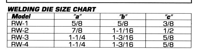
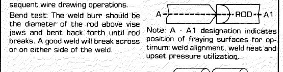
7 B. The weld heat duration determines the amount of weld upset and expelled metal projecting from the weld zone. C. All welds should be completed before the closed space stop screw (E) touches the movable head. D. The amount of open space must be sufficient to allow the weld to take place completely without making contact with the closed stop screw (E) TO SET CLOSED STOP SCREW The closed stop screw is set at the factory to provide.010 space between dies when the heads are in the full upset (closed) position. Eventually due to wear, the screw may have to be readjusted. If so, follow this procedure: A. Turn power off so dies won t weld to each other. B. Squeeze stationary and movable head together. C. Loosen locknut (J). D. With scale at inside edges of dies, turn head stop (E) until there is.010 between inside edges of dies, then tighten locknut (J). E. Release heads. 3.3 UPSET PRESSURE MECHANISM Set the air regulator on the left side of the welder housing. The upset pressure is changed by adjusting the UPSET air regulator located on the left of the welder. 3.4 UPSET PRESSURE TIME The amount of time pressure is applied to the weld zone prior to application of heat is called SQUEEZE. The SQUEEZE time is programmed in a range of 00 to 99 cycles. 3.5 WELDING DIES AND DIE SHOES Welding dies serve three purposes: (1) to carry current and voltages for welding, (2) to align material ends, and (3) to prevent slippage during the weld cycle. Small wire must be placed into small grooves and large wire into the large grooves. Flat stock must be placed against the stop in the rear of the dies. The die shoe holds the material securely into the lower welding die during the weld process. 7
8 3.6 CLAMPING MECHANISM The clamping pressure is controlled by adjusting the CLAMP AIR REGULATOR located on the left of the welder. Enough clamp pressure must be provided to prevent the material from slippage in the dies. 3.7 FOOT SWITCH CONTROL All operations on the welder are performed by a single down-stroke of the foot switch, when the foot switch is released, the operating parts are automatically re-spaced, ready for the next weld operation. 4.1 WELDING DIES AND DIE SHOES INFORMATION Description: Welding dies Lower conducting electrode and clamp jaw Welding die shoes Upper clamping member Welding dies and die shoes in poor condition are the main causes of bad welds. 8

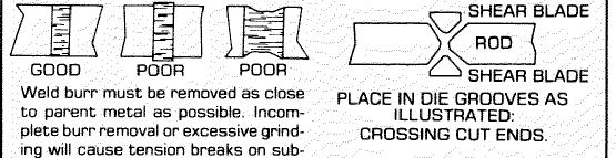
9 Care of die sets: 1. Use a brass or fiber blade to remove particles of flashings that build-up on die sets. Excessive flash build-up causes die burns on material and shorting of die sets. 2. Do not attempt to clamp material that is not suited for welder into dies sets. Undersize material will slip and burn die grooves, oversize materials will overstress clamping parts. 3. Do not use welding die sets for a vise. These parts will not withstand the mechanical abuse. 4. Whenever welding dies are replaced, clean bottoms of dies and corresponding die seats to a bright and clean condition before bolting them tightly into place. An oxidized surface will insulate the welding dies and reduce effective welding voltage. 5. Welding die shoes must swivel freely within clamp arm pivots to prevent cracking of die shoes. File down die shoe boss if necessary. 6. Welding die sets will wear with use and must be changed occasionally for good welding results. Keep an adequate supply of replacement parts available. Wire and rod slippage is a problem caused by poor die sets and a major cause of wire breaks. 9
10 10
11 5.0 TYPICAL SEQUENCE OF OPERATION Wire to be joined must be free of rust, corrosion or other insulating materials where it contacts welding dies. 5.1 Cut wire ends to best joint configuration. 5.2 Set welding platen for proper die opening. 5.3 Select proper weld heat range. 5.4 Place wire into welding dies so as the ends touch and abut midway between welding dies. 5.5 Push foot switch down to clamp and start weld process. 5.6 Heat is imparted to wire ends through faying surfaces. 5.7 Movable platen under upset pressure moves toward a closed position due to loss of compression yield strength of wire. 5.8 A weld controller terminates electrical power flow through wire 5.9 Actual weld or coalescence is formed after electrical power flow stops and material is hot forged together with remaining upset pressure Welded material quickly cools under pressure Remove stock from dies by releasing foot switch. 6.0 SPECIAL ADJUSTMENTS 6.1 HEADPIECE OPEN ADJUSTMENT (Adjusts open position of headpiece) Adjustment See and (4D) Rotate space adjusting nuts as needed to provide the desired open space between the dies. Then lock the nuts into position. 6.2 HEADPIECE CLOSED ADJUSTMENT (Prevents welding dies from touching) Adjustment See (4.0) Make the adjustment, by using headpiece closed adjusting screw, so that when the movable headpiece is pushed by hand the dies will not touch and have approximately.005 to.010 between welding dies. 11
12 7.0 PREVENTIVE MAINTENANCE TECHNIQUE Keep in Mind that these welders are precision built to last many years, but will require good maintenance procedures. They are designed to be as automatic as possible with a minimum dependence on the ability of the operator. Adjustments must be made by those thoroughly familiar with the operating principles of the welders. 7.1 WELDING DIE NOTES Welding dies and die shoes in poor condition are the primary caused of bad welds Check die sets for excessive wear and replace if necessary Clean weld die bottoms to remove oxides with emery cloth placed on a flat surface Clean die seats with emery cloth to brighten contact areas After cleaning of dies be sure to wipe off with soft clean cloth Completely tighten dies into seats to assure a good contact Worn die shoes will not hold stock during a weld cycle, change steel faces or replace complete shoes. 7.2 WEEKLY Tighten all loose parts. 7.3 QUARTERLY Repeat above service items Check grease requirements on clamp arms pivot shafts and lubrication points Check anneal parts and replace all worn or broken assemblies Check contacts on magnetic contactor for worn contacts Clean heat switch contacts with low residue cleaner and recoat with petroleum jelly. 7.4 ANNUALLY Repeat previously noted items Check for wear in clap arm pivots Clean inside and outside of welder Check grease requirements on headpiece slide shafts, grease lightly Caution: make sure that power supply is disconnected before servicing welder in anyway! 12
13 7.5 WELDING DIES AND DIE SHOES INFORMATION Description: Welding dies Lower conducting electrode and clamp jaw. Welding die shoes Upper clamping member. Welding dies and die shoes in poor condition are the main causes of bad welds. Care of die sets: Use a brass or fiber blade to remove particles of flashings that build-up on die sets. Excessive flash build-up causes die burns on material and shorting of die sets Do no attempt to clamp material that is not suited for welder into die sets. Undersize materials will slip and burn die grooves, oversize materials will overstress clamping parts Do not use welding die sets for a vise. These parts will not withstand the mechanical abuse Whenever welding dies are replaced, clean bottoms of dies and corresponding die seats to a bright and clean condition before bolting them tightly into place. An oxidized surface will insulate the welding dies and reduce effective welding voltage Welding die shoes must swivel freely within the clamp arm pivots to prevent cracking of die shoes. File down die shoe boss if necessary Welding die set will wear with use and must be changed occasionally for good welding results. Keep and adequate supply of replacement parts available. Wire and rod slippage is a problem caused by poor die sets and a major cause of wire breaks. 13
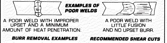
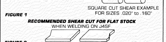
14 8.0 SUGGESTED SETTINGS 8.1 CLAMP PRESSURE The clamp pressure is typically set for 30 lbs. For all stock up to middle of size range. For larger sizes 40 to 60 lbs. is recommended. 8.2 UPSET PRESSURE For air operated welders set the pressure to 30 lbs. for steel diameters from the minimum up to mid range of the welder size specification. For larger than middle or range sizes the air regulator may be gradually adjusted upward until the maximum size material is reached. For most applications the maximum pressure setting is 60 lbs. For non-ferrous materials, lesser setting should be used. Consult the factory for non-ferrous applications. 8.3 WELD TIME The weld current time is controlled to the nearest cycle. The timer has a range of settings from 01 to 99 cycles. For most material sizes 15 cycles may be used. This is only a suggested mid range value, and will be determined by the (welds per minute) requirement of the welding task. When larger material sizes are to be welded, first increase the heat setting then readjust the weld time to obtain the desired weld. 8.4 WELD HEAT The heat level is controlled from 0 to 99 percent The level selected should be lowest value consistent with good weld quality. In order to increase the weld per minute, rate it may be necessary to increase the heat level above what might be needed on a lower production basis. 8.5 WELD QUALITY Figure 1 illustrates the types of welds obtainable on a butt welder. The stronger welds are those that have the larger weld burr It is possible to reduce the size of the burr and still obtain a strong weld. If the weld parameters are set to completely eliminate the burr, the weld strength will be reduced and may not meet the required weld tests. 14
15 8.5.3 If a reduced burr weld is desired the stock to be welded should first be flush cut on the rod ends that are to be joined If the weld burr is too large, reduction of the upset pressure will result in a reduced burr. Lowering of the upset pressure generally requires that the weld heat level also be reduced. This can be accomplished by decreasing the number of heat cycles or lowering the heat percentage The control supplied on this welder allows programming of multiple heat impulses to the weld zone. (OPTIONAL FEATURE) It has been demonstrated that for certain types of materials the heat impulse feature can aid in obtaining a reduced weld burr, while holding the reduction on weld strength to minimum Below is a sample of weld parameters used to obtain a good weld by conventional single impulse welding. The corresponding weld parameters are shown using multiple impulse welding. To obtain a reduced burr on the same type and size of material, both two and three impulse programs are illustrated. 8.6 The values shown are typical for the low end of the welder capacity range. For larger sizes of material use increasing heat levels and heat time settings. SINGLE IMPULSE TWO IMPULSE THREE IMPULSE Clamp pressure 40 lbs. 40 lbs. 40 lbs. Upset pressure 30 lbs. 30 lbs. 30 lbs. Squeeze time 20 cycles 20 cycles 20 cycles Hold time 20 cycles 20 cycles 20 cycles Off time 10 cycles 10 cycles 10 cycles Impulses Heat level 30 percent 30 percent 30 percent Heat time 15 cycles 07 cycles 04 cycles Cool time 00 cycles 05 cycles 03 cycles 15

16 16
17 9.0 DIAGNOSTIC CHART FOR TROUBLE-SHOOTING WELDING ACTION CAUSE REMEDY Weld action normal but weld burr doesn t extend beyond wire Lack of open space Increase open space until desired burr is obtained Molten metal is blown out and ends not joined Weld area heats up but weld is not complete Weld has complete burr but is dry and breaks off below surface of wire Welds good but poorly aligned Ends of wire buckle and may not weld Varying weld results Weld heat too high Weld limit switch Stock is too small Weak clamp spring Low heat Secondary transformer connections Loose or dirty welding dies Starting space adjust Upset pressure too great Limit switch settings High carbon steel wire Welding dies & die shoes Starting space Loose pivot centers Upset pressure too great Low weld heat Stock slipping Varying weld voltages Rod condition variations Dies and die shoes Flashings Rod cuts Lower heat settings Set limit switch properly Check size rating of welder Replace clamp springs Increase weld heat Clean and tighten transformer connections Clean welding dies and surfaces Decrease starting space Lower upset pressure Reset limit switch to specifications Carbon-steel wire often appears like this, process wire by annealing weld before removing burr Replace worn dies and shoes Decrease starting space Return heads to factory Decrease upset pressure Increase weld heat Worn dies and shoes Check electric lines Clean and tighten transformer connections to heads Clean rod where clamped in dies Replace dies and shoes Clean build-up of flash materials 9.1 ELECTRICAL TROUBLE-SHOOTING OF WELDER (Caution!! Extreme care should be exercised when making these tests. Dangerous voltages are present in the welder. Only persons familiar with electrical safety precautions should perform these tests.) TROUBLE-SHOOTING TABLE (see section ) This electrical trouble-shooting table is furnished as a suggested method of trouble-shooting the welder. The individual steps of the table should be performed in the order given, to make the test valid. The electrical schematic (section 10) furnished for these tests shows the table test points. This table may be used for welders with a different but closely related wiring by using corresponding test points. During all tests, line voltage should be connected to L1 & L2 of the welder. 17
18 9.1.2 FINAL ELECTRICAL CHECKS Set the heat to 99% and 99CYL on the control. Connect the voltmeter across the welding dies. Press the operating switch. The meter reading will typically be less than 10 VAC. Consult the weld specification sheet for this value MODEL RW1,2,3,4 Use Schematic C5820 CONTROL TEST LEAD CONNECTION METER READING PROBLEM IF NO READING L2 SCR-K1 Line Voltage Open wire or open FU1 fuse TB2-9 TB VAC Bad control transformer T2 or FU3,4 fuse open * Bad Control pulse output TB1-18 TB volt pulse TB2-3 TB VAC Bad control output to air L2 H1 Approximately 50% of line voltage L2 H1 Approximately 100% of line voltage ** TB1-11 TB1-12 ** TB1-15 TB1-23 valves Bad SCR pack Bad SCR pack PRESS FOOT SWITCH Temperature switch open 0 Ohms 0 Ohms FS1 foot switch open X CONTROL HEAT SETTINGS CONTROL HEAT CYCLE SETTINGS X 50% 99CYL X X 50% 99CYL X 99% 99CYL Note: to perform repairs consult section 13 for parts identification *CAUTION! An isolated scope must be used for this test. Consult control manual for additional tests. ** Power must be removed from the welder for these tests. 18

19 10.0 ELECTRICAL SCHEMATIC 19
20 20
21 11.0 SAFETY REMINDERS The following accident prevention information is presented to eliminate potential hazards while operating, inspecting or repairing Micro-Weld electric resistance welding equipment. Important safety compliance information for Micro-Weld Welders. GENERAL 1. Prior to using equipment, an operator must be instructed on basic operation and malfunction methods, by qualified personnel. 2. Safety eyeglasses must be worn by all personnel operating or servicing welders. 3. Use safety equipment properly and keep safety equipment on welders. 4. Determine that both operating voltages and hertz (cycles) of power supply correspond to ratings listed on weld nameplate located on weld housing. 5. Check nameplate ratings and keep within capacities and material categories stated therein. 6. Adjustment or repairs must be made by persons thoroughly familiar with operating principles of welder. 7. Welder must be disconnected from power supply prior to maintenance or repair procedures. 8. Reduce air supply pressures or disconnect from air source, for pneumatically equipped welders, prior to maintenance or repair procedures. 9. Welders equipped with water cooling accessories must have water supply turned off during idle periods and allow only enough water to flow to cool heated components during weld operation. ELECTRICAL 1. Refer to National Electrical Code and local regulations for adequate electrical wiring to power welder. Do not operate welder with inadequate electrical power supply cords or cable. 2. All welders must be ground through power supply and welder ground connection terminal securely tightened. 3. All welders must be able to be disconnected from power source either by a double breaking disconnect switch or unplugged by standard rated plugs. 4. All welders must be fused to prevent injury should an electrical malfunction occur. Welders must never be fused for an ampere load that exceeds the ratings stated on weld nameplate. Normally welders are fused using the nameplate rated load; time lag parameters functional to standard fuses allow this specification. 5. Electric power cords to welder must be kept in good condition. Report any damage or potential hazards to maintenance personnel. 6. The weld heat selection switch, potentiometer or range selection devices must not be changed to a new position while a weld operating is in process. 21
22 12.0 BUYERS GUIDE HOW TO ORDER PARTS: You must provide 1. Machine Model 2. Machine Serial Number 3. Voltage Then identify part(s) on part list (last page in book) and provide MICRO with the circled number CALL MICRO at Or fax to: Provide MICRO with your company name, address and purchase order number. 22
23 13.0 PARTS LIST 23
24 24
25 25
26 PARTS LIST RW SERIES RING WELDERS MODEL/ PART NO. DESCRIPTION ITEM # RW-01 Head basic RW-02 Head complete RW-03 Shaft shield RW-04 Slide shaft bearings RW-05 Closed head stop RW-06A Front arm bushing RW-06B Rear arm bushing RW-07 Key RW-08L Left clamp arm RW-08R Right clamp arm RW-09 Clamp cylinder RW-09A Clamp cylinder Bracket RW-09B Clevis RW-09D Clamp link RW-10 Clamp lever RW-11 Clamp arm spacer RW-12 Clamp lever link bolt RW-13 Upset cylinder RW-14 Upset coupling RW-15 Insulating washers RW-16 Pull rod RW-17 Insulating tube RW-18 Nipple RW degree el RW-20 Hose fitting RW-28 Regulator bracket RW-30 Filter/regulator/lubricator RW-31 Air Gage RW-32 Quick release air coupling RW-33 Electric sub plate RW-34 Terminal strip RW-35 Line block RW-36 Transformer RW-37 Transformer ring RW-37A Transformer stud
27 PARTS LIST RW SERIES RING WELDERS MODEL/ PART NO. DESCRIPTION ITEM # RW-38 Control step-down RW-39 Fuse holder RW-39A Fuse RW-40 Time delay relay RW-41 Air valve RW-42 Foot switch RW-RA1 Air sub plate RW-RA7 Street el 90 degree RW-RA6 El 90 degree RW-RA5 Tee RW-RA4 Hose fitting RW-RA3 Nipple RW-RA2 Connector RW-RA8 Muffler RW-58 Weld dies RW-59 Die bolt RW-60BC Shoes RW-60S Shoes, steel faced RW-SS1 Solid state control Appl. RW-SS2 SCR pack RW-SS3 Heat sink RW-SS4 Resistor RW-SS5 Fuse RW-SS6 Fuse holder (set)
28 PARTS LIST RW SERIES RING WELDERS MODEL/ PART NO. DESCRIPTION ITEM # RW-121 Flash shield RW-122 Flash shield bracket RW-105 Weld transformer 460V RW-105A Primary 230V RW-105B Secondary 230V RW-103 Truck RW-131 Stationary mounts (set of 4) RW-132 Caster, stationary RW-132 Caster, movable
MICRO WELD MODEL GP1, GP2 CERAMIC FUSION BUTT WELDERS MICRO PRODUCTS COMPANY SERVICE MANUAL
 MICRO WELD MODEL GP1, GP2 CERAMIC FUSION BUTT WELDERS MICRO PRODUCTS COMPANY SERVICE MANUAL 1 TABLE OF CONTENTS 1.0 SPECIFICATIONS 2.0 GENERAL OPERATING INSTRUCTIONS 3.0 BASIC OPERATING PARTS 4.0 BASIC
MICRO PRODUCTS COMPANY MANUFACTURES OF PRECISION WELDING MACHINES MODEL SEMT FINE WIRE BUTT WELDER SERVICE MANUAL
 MICRO PRODUCTS COMPANY MANUFACTURES OF PRECISION WELDING MACHINES MODEL SEMT FINE WIRE BUTT WELDER SERVICE MANUAL 1 TABLE OF CONTENTS 1.0 SPECIFICATIONS 2.0 GENERAL OPERATING INSTRUCTIONS 3.0 BASIC OPERATING
POWER PINNER BENCH HAND WELDER 7250 OPERATOR S MANUAL
 POWER PINNER BENCH HAND WELDER 7250 OPERATOR S MANUAL Copyright: November 20, 2018 Revised: Serial No. Gripnail Corporation An Employee Owned Company 97 Dexter Road East Providence, Rhode Island 02914-2045
FOREWORD. Communication on these practices is most welcome. MECHELONIC. The birth of Mechelonic took place a decade ago in January 1972.
 FOREWORD Mechelonic Welders Pvt Ltd This booklet has been prepared by our technical team in order to guide the Industries employing Resistance Welding Technology in their line of manufacture. We have tried
FW66 FORESTRY WINCH FW66. Owner s Manual 19/02/2016
 FW66 FORESTRY WINCH FW66 19/02/2016 Owner s Manual TABLE OF CONTENTS INTRODUCTION ---------------------------------------------------------------------------------- 2 INTENDED USE -----------------------------------------------------------------------------------
Proweld Equipment Owner & Maintenance Manual FIELD 12 TRENCH (Widos 4900)
") Proweld Equipment Owner & Maintenance Manual FIELD 12 TRENCH (Widos 4900) 35 Green Street, PO Box 653, Malden, MA 02148 Tel: (781) 321-5409 - Fax (781) 321-4421 - Toll Free: (800) 343-3618 www.asahi-america.com
Proweld Equipment Owner & Maintenance Manual FIELD 12 TRENCH (Widos 4900) 35 Green Street, PO Box 653, Malden, MA 02148 Tel: (781) 321-5409 - Fax (781) 321-4421 - Toll Free: (800) 343-3618 www.asahi-america.com
AP5K-C Precision AC Double-Pulse Spot Welding Machine User s Manual Shenzhen Will-Best Electronics Co., Ltd
 AP5K-C Precision AC Double-Pulse Spot Welding Machine User s Manual Shenzhen Will-Best Electronics Co., Ltd 1 Content 1. Introduction...3 1.1 Functions...3 1.2 Units of AP5K-C...4 2. The Initial Installation
USER S OPERATING AND INSTRUCTION MANUAL
 Grand Rapids, Michigan, U.S.A. 49504-5298 USER S OPERATING AND INSTRUCTION MANUAL MODEL 738 MINI CHIP SLICER 0738S20000-CV INDEX Section Description Document No. Page No. SAFETY INSTRUCTIONS --------------------------------------
SUNSTONE WELDERS AC WELDER USER MANUAL
 SUNSTONE WELDERS AC WELDER USER MANUAL 2 Sunstone Welders - AC Welder User Manual TABLE OF CONTENTS Forward... p.4 Introduction... p.5 Welder Setup... p.5 Welder Interface... p.6 Welding Attachments...
READ THIS MANUAL CAREFULLY BEFORE ASSEMBLY, TESTING & OPERATING
 The Operator must thoroughly read and understand this manual before operating the dust collector or commencing any servicing. Care should be taken to follow all safety rules and warning instructions. READ
Welding & Fabrication Tools Mini VaR Tool Kit
 With Volta Tools You Can Never Go Wrong! Fast and simple belt installation. Unique and versatile design - compact, rugged and easy-to-use. Designed for both shop and field use. Light-weight construction.
Service Manual For the E Ride 26
 Service Manual For the E Ride 26 For: Training Troubleshooting Adjustments Contents 1 Cautions ------------------------------------------------------------------------ 2 Safety Information ----------------------------------------------------------
Cutlass Fasteners, Inc. 83 Vermont Ave., Unit 6, Warwick, RI Tel: (401) Fax: (401) cutlass-studwelding.com
 Fax: (401) cutlass-studwelding.com") MODEL : A-58 ARC WELD GUN PART NO. : 602-378A SERIAL NO. : PLEASE READ THIS OPERATION AND MAINTENANCE MANUAL CAREFULLY BEFORE USING YOUR NEW CUTLASS STUD WELDER. COPYRIGHT CFI 2009 email: sales@ PAGE -
MODEL : A-58 ARC WELD GUN PART NO. : 602-378A SERIAL NO. : PLEASE READ THIS OPERATION AND MAINTENANCE MANUAL CAREFULLY BEFORE USING YOUR NEW CUTLASS STUD WELDER. COPYRIGHT CFI 2009 email: sales@ PAGE -
EU150-EU200-EU400 CRIMPER OPERATORS MANUAL
 EU50-EU00-EU00 CRIMPER OPERATORS MANUAL SAFETY PRECAUTIONS READ INSTRUCTIONS AND IDENTIFY ALL COMPONENT PARTS BEFORE USING CRIMPER KEEP HANDS AWAY FROM PINCH POINTS CONSULT HOSE AND FITTING MANUFACTURER
EU1000 CRIMPER OPERATORS MANUAL WITH ACTTM CONTROLLER
 EU1000 CRIMPER OPERATORS MANUAL WITH ACTTM CONTROLLER SAFETY PRECAUTIONS READ INSTRUCTIONS AND IDENTIFY ALL COMPONENT PARTS BEFORE USING CRIMPER KEEP HANDS AWAY FROM PINCH POINTS CONSULT HOSE AND FITTING
MODEL 185R Kontrol-Karrier Operator s Manual for Morse Kontrol-Karrier
 Contents Page Receiving Procedures.................... 1 Warranty............................. 1 Safety Information..................... 1-2 Machine Description................... 3 Operating Instructions....................
FAST SPOTTER WT-FS-5.0
 . FAST SPOTTER WT-FS-5.0 Installation, Operating and Maintenance Manual WELDING TECHNOLOGIES www.weldingnet.com 1365 Horseshoe Dr., Blue Bell, PA 19422 Phone: 610-278-9325 Fax: 610-278-9325 Toll Free Number:
2200-Lb. Semi-Electric Stacker OWNER S MANUAL
 2200-Lb. Semi-Electric Stacker OWNER S MANUAL WARNING: Read carefully and understand all ASSEMBLY AND OPERATION INSTRUCTIONS before operating. Failure to follow the safety rules and other basic safety
Cutlass Fasteners, Inc. 83 Vermont Ave., Unit 6, Warwick, RI Tel: (401) Fax: (401) cutlass-studwelding.com
 Fax: (401) cutlass-studwelding.com") MODEL : PHM-12 ARC WELD GUN PART NO. : PHM-12 (PHM-12-RS) SERIAL NO. : PLEASE READ THIS OPERATION AND MAINTENANCE MANUAL CAREFULLY BEFORE USING YOUR NEW CUTLASS STUD WELDER. COPYRIGHT CFI 2009 email: sales@
MODEL : PHM-12 ARC WELD GUN PART NO. : PHM-12 (PHM-12-RS) SERIAL NO. : PLEASE READ THIS OPERATION AND MAINTENANCE MANUAL CAREFULLY BEFORE USING YOUR NEW CUTLASS STUD WELDER. COPYRIGHT CFI 2009 email: sales@
Service Manual For the E Ride 26
 Service Manual For the E Ride 26 For: Training Troubleshooting Adjustments Rev. 04/2013 Contents 1 Cautions ------------------------------------------------------------------------- Page 4 2 Safety Information
OPERATION MANUAL. A220 Arc Welding Machine. Serial Number: Where Purchase: Date of purchased:
 OPERATION MANUAL A220 Arc Welding Machine Serial Number: Where Purchase: Date of purchased: CONTENT 1.Safety... 2 2. Summary... 4 3. Electrical principle drawing... 5 4. Specifications... 6 5. Operation
11, 000- L b. E x t r e m e - D u t y P a l l e t Tr u c k OWNER S MANUAL
 11, 000- L b. E x t r e m e - D u t y P a l l e t Tr u c k OWNER S MANUAL WARNING: Read carefully and understand all ASSEMBLY AND OPERATION INSTRUCTIONS before operating. Failure to follow the safety rules
ENel Sp. z o. o. - WROCŁAW DESIGN AND MANUFACTURE OF POWER ELECTRONIC DEVICES INVERTER WELDING MACHINE ENEL250A USER MANUAL DEALER:
 ENel Sp. z o. o. - WROCŁAW DESIGN AND MANUFACTURE OF POWER ELECTRONIC DEVICES INVERTER WELDING MACHINE ENEL250A USER MANUAL DEALER: . INTRODUCTION This manual contains information that will allow to take
Installation Instructions, Pressure Regulator Series Manual Model: 20313, Air motor Operated: F20313, Hydraulic Motor Operated: G20313
 Installation Instructions, Pressure Regulator 20313 Series Manual Model: 20313, Air motor Operated: F20313, Hydraulic Motor Operated: G20313 1. GENERAL ------------------------------------------------------------------------------
WE21S GMA (MIG) Butt Joint With Backing
 Butt Joint With Backing") Uniform Procedures For Collision Repair WE21S GMA (MIG) Butt Joint With Backing 1. Description This procedure describes methods for making and inspecting GMA (MIG) butt joint with backing welds on automotive
Uniform Procedures For Collision Repair WE21S GMA (MIG) Butt Joint With Backing 1. Description This procedure describes methods for making and inspecting GMA (MIG) butt joint with backing welds on automotive
booster EX2 / EX3 Operating Manual Extrusion Welder Weldy AG Galileo-Strasse 10 CH-6056 Kaegiswil / Switzerland TECHSPANGROUP
 booster EX2 / EX3 Extrusion Welder Operating Manual Weldy AG Galileo-Strasse 10 CH-6056 Kaegiswil / Switzerland TECHSPANGROUP Australia: Tel. 1-800 148 791 Fax. 1-800 148 799 www.weldy.com.au New Zealand:
Keep your head out of the gas. When you are welding, air extractor should be used to prevent inhalation of gas.
 Installation Instructions for 81542 TIG Welder 200 Page 1 Safety Caution! In the process of welding or cutting, there will be possibility of injury, so please take personal protection into consideration
CPT 60 Powerfloat. User & Safety Instructions
 CPT 60 Powerfloat User & Safety Instructions This handbook contains operating and maintenance instructions for the Refina CPT60 Power float Please keep it in a safe place. You may need to refer to it at
2200-Lb. Stacker. Fixed Straddle Leg OWNER S MANUAL
 2200-Lb. Stacker Fixed Straddle Leg OWNER S MANUAL WARNING: Read carefully and understand all ASSEMBLY AND OPERATION INSTRUCTIONS before operating. Failure to follow the safety rules and other basic safety
HALSEY TAYLOR OWNERS MANUAL Classic TM Series Barrier-Free Water Coolers Refrigerated Fountains with Back Panel
 HALSEY TAYLOR OWNERS MANUAL Classic TM Series BarrierFree Water Coolers Refrigerated Fountains with Back Panel Figure HTERQ Figure HTSRQ Figure 3 HTSERQ Figure HTESRQ Figure 3 Model HTERQ HTSRQ HTSERQ
DISSTON WELDING PRODUCTS TIG/MMA-160/180/200/250D. Welding Machines
 DISSTON WELDING PRODUCTS TIG/MMA-160/180/200/250D Welding Machines FOR SAFE OPERATION: Keep the work area clean. Cluttered work areas invite injuries (indoor and outdoor). Consider the work environment.
INSTRUCTION MANUAL FOR WIRE WELDING MACHINE
 INSTRUCTION MANUAL FOR WIRE WELDING MACHINE IMPORTANT: BEFORE STARTING THE EQUIPMENT, READ THE CONTENTS OF THIS MANUAL, WHICH MUST BE STORED IN A PLACE FAMILIAR TO ALL USERS FOR THE ENTIRE OPERATIVE LIFE-SPAN
INSTALLATION AND OPERATION MANUAL
 Pneumatic Wheel Lift Model: RWL-50T REV. A PLEASE READ THE ENTIRE CONTENTS OF THIS MANUAL PRIOR TO INSTALLATION AND OPERATION. BY PROCEEDING YOU AGREE THAT YOU FULLY UNDERSTAND AND COMPREHEND THE FULL
Tube-Line Bale Feeder BF-5600SL. Operator's Manual
 Tube-Line Bale Feeder BF-5600SL Operator's Manual 2 Contents Safety.......5 Operation.....7 Maintenance...7 Troubleshooting....9 Parts.....11 Specifications Weight : 1960 lbs (empty) Capacity : 2 Bales,
TABLE OF CONTENTS. Vacuum Cleaner. Model No. MC-CG Bagless Canister Red North America
 Order No.: MAC1412002CE Vacuum Cleaner Model No. MC-CG902-02 Bagless Canister Red North America TABLE OF CONTENTS PAGE 1 Specifications ----------------------------------------------------- 2 2 Disassembly
High Temperature Aging Cell Instruction Manual
 High Temperature Aging Cell Instruction Manual Part No. 760140001EA Rev. D TABLE OF CONTENTS Section Page Figure 1 General Information... 1 2 Safety Considerations... 3 3 Un-pressurized Testing Procedure...
SYSTEM 600 GENERAL MAINTENANCE AND ADJUSTMENT GUIDE
 SYSTEM 600 GENERAL MAINTENANCE AND ADJUSTMENT GUIDE If you follow a routine maintenance schedule your system 600 will give you years of reliable service with a minimum of down time. This guide outlines
1-300 SERIES Endover Rotator Operator s Manual for Morse End-Over-End Drum Rotators Series
 Contents Page Receiving Procedures.................... 1 Warranty............................. 1 Safety Information..................... 1-2 Machine Description................... 3 Operating Instructions....................
Thermocouple & Fine Wire Welder Model No. L60+
 Thermocouple & Fine Wire Welder Model No. L60+ Web e-mail Telephone www.labfacility.com sales@labfacility.com +44(0)1243 871280 Issue: 050004.OM.G Web e-mail Telephone www.labfacility.com sales@labfacility.com
WE01A GMA (MIG) Plug Weld
 Plug Weld") Uniform Procedures For Collision Repair WE01A GMA (MIG) Plug Weld 1. Description This procedure describes methods for making and evaluating gas metal arc (GMA) plug welds (MIG plug welds) on all types
Uniform Procedures For Collision Repair WE01A GMA (MIG) Plug Weld 1. Description This procedure describes methods for making and evaluating gas metal arc (GMA) plug welds (MIG plug welds) on all types
Operator s Manual for Morse Mobile-Karrier for 55-Gallon Plastic or Steel Drum
 Contents Page Receiving Procedures.................... 1 Warranty............................. 1 Safety Information..................... 1-2 Machine Description................... 3 Operating Instructions....................
HALSEY TAYLOR OWNERS MANUAL Classic TM Series Barrier-Free Water Coolers Refrigerated Fountains with Back Panel
 HALSEY TAYLOR OWNERS MANUAL Classic TM Series BarrierFree Water Coolers Refrigerated Fountains with Back Panel Figure HTERQ Figure HTSRQ Figure 3 HTSERQ Figure HTESRQ Figure 3 Model HTERQ HTSRQ HTSERQ
INSTRUCTION MANUAL WARNING: BEFORE USING THE MACHINE READ THE INSTRUCTION MANUAL CAREFULLY!
 INSTRUCTION MANUAL WARNING: BEFORE USING THE MACHINE READ THE INSTRUCTION MANUAL CAREFULLY! SECTION 1 : PRODUCT AND COMPANY IDENTIFICATION PRODUCT NAME : SYNONYMS : PRODUCT CODES : Weldability ARC140i
INVERTER IBGT MIG WELDING MACHINE OPERATION MANUAL
 ionmig 250 INVERTER IBGT MIG WELDING MACHINE OPERATION MANUAL IMPORTANT: Read this Owner s Manual Completely before attempting to use this equipment. Save this manual and keep it handy for quick reference.
BUSH HOG LAND MAINTENANCE REPAIR PARTS MANUAL MODELS: HS1736B, HS1742B, HS1836B, HS1842B, HS2036K, HS2042K HOME SERIES ZERO TURN MOWER SECTION: 85
 BUSH HOG LAND MAINTENANCE REPAIR S MANUAL MODELS: HSB, HSB, HSB, HSB, HS0K, HS0K HOME SERIES ZERO TURN MOWER SECTION: 0 Griffin Ave. Selma, AL 0 () -00 Parts Ordering -00-0- Fax -00-- www.bushhog.com OCTOBER,00
TF20 Tray Feeder. Instruction Manual. for JEDEC and IEC Standard Trays
 for JEDEC and IEC Standard Trays Instruction Manual 096-0243-003 Data I/O assumes no liability for errors, or for any incidental, consequential, indirect, or special damages, including, without limitation,
INSTRUCTION MANUAL FOR WIRE WELDING MACHINE
 INSTRUCTION MANUAL FOR WIRE WELDING MACHINE IMPORTANT: BEFORE STARTING THE EQUIPMENT, READ THE CONTENTS OF THIS MANUAL, WHICH MUST BE STORED IN A PLACE FAMILIAR TO ALL USERS FOR THE ENTIRE OPERATIVE LIFE-SPAN
HOW TO SELECT A RESISTANCE WELDER
 HOW TO SELECT A RESISTANCE WELDER Despite the fact that resistance welding is one of the most widely used joining processes in the sheet metal fabricating industry, the proper selection of a resistance
CBE 600 SERIES GRAVITY PACKER
 CBE 600 SERIES GRAVITY PACKER Safety - Installation - Operation - Maintenance 1 OF 16 FOREWARD This manual has been prepared to assist you with your Choice Bagging Equipment, Ltd. bag packaging equipment.
BakeMax Dough Mini Moulder BMMDM02
 BakeMax Dough Mini Moulder BMMDM02 2 Instruction Manual 1. Preface ------------------------------------------- P2 2. Machine Introduction -------------------------------- P2 3. Machine Specification and
THOMSEN T-29 CORDLESS ELECTRIC ICE EDGER
 Page 1 THOMSEN T-29 CORDLESS ELECTRIC ICE EDGER Proudly Built In The USA! www.thomsenedgers.com icecat@thomsenedgers.com 1-800-423-6025 Page 2 Proudly Built In The USA! www.t hom senedgers.com icecat@thom
OPERATOR S MANUAL. LINKIT Series LKS300/LKS450 Portable Conveyor. InterQuip USA LLC interquip.net DISTRIBUTED BY: OPERATOR S MANUAL
 OPERATOR S MANUAL LINKIT Series LKS300/LKS450 Portable Conveyor DISTRIBUTED BY: InterQuip USA LLC 203.322.2600 interquip.net 1 IMPORTANT Read, understand and obey these safety rules and operating instructions
USER S OPERATING AND INSTRUCTION MANUAL
 Grand Rapids, Michigan, U.S.A. 49504-5298 USER S OPERATING AND INSTRUCTION MANUAL MODEL 619-MDP DOUGH PRESS 0619S20000-CV3 619-MDP DOUGH PRESS INDEX Section Description Document No. Page No. SAFETY INSTRUCTIONS
SQ-1 ROOF TRUSS WEG-IT TABLE
 WEG-IT Steel Top Table SQ1 Service SQ-1 ROOF TRUSS WEG-IT TABLE Operators Manual FOREWORD This manual explains the proper maintenance of Square 1 Design Roof Truss WEG-IT Table as well as periodic inspection
HYDRAULIC TRUCK RESTRAINT OWNER S MANUAL
 HYDRAULIC TRUCK RESTRAINT OWNER S MANUAL TR 2000 - TRUCK RESTRAINT Serial Number: Model: Customer: Date Shipped: Options: OWNER S MANUAL Table Of Contents Safety Information Warning... 3 Installation...
Operator s Manual Model ARC Amp DC Welder
 Operator s Manual Model ARC200 200 Amp DC Welder WARNING: Do not assemble, install, or operate this equipment without reading ALL of this manual and the safety precautions and warnings illustrated in this
WE11S GMA (MIG) Fillet Weld
 Fillet Weld") Uniform Procedures For Collision Repair WE11S GMA (MIG) Fillet Weld 1. Description This procedure describes methods for making and inspecting GMA (MIG) fillet welds on automotive steel. 2. Purpose The
Uniform Procedures For Collision Repair WE11S GMA (MIG) Fillet Weld 1. Description This procedure describes methods for making and inspecting GMA (MIG) fillet welds on automotive steel. 2. Purpose The
Car and Counterweight Frames
 Car and Counterweight Frames CAR FRAME (SLING) AND PLATFORM COUNTERWEIGHT FRAME Every attempt has been made to ensure that this documentation is as accurate and up-to-date as possible. However, Vertical
Horizontal Belt Stacker
 Shipping & Mailing Inserter Horizontal Belt Stacker TM for Relay Systems Operator Guide International English Edition August 1, 2015 Note: This equipment has been tested and found to comply with the limits
OPERATION MANUAL 1.5HP Dust Cyclone
 OPERATION MANUAL 1.5HP Dust Cyclone MODEL NO.: CDC-1090P The Operator must thoroughly Read and understand this Manual before operating the Dust collector or commencing Any servicing. Care should be Taken
Operating Instructions
 Operating Instructions Series B37000 Hose Reels BB37118 L CB37118 L EB37118 L12D BB37122 L CB37122 L EB37122 L12D BB37128 L CB37128 L EB37128 L12D Dimensional Data C A B D Part # A B C D BB/CB37118 L 31
PARTS CATALOG 6000/6001 ELITE SERIES SURGICAL TABLES INCLUDING BATTERY MODELS
 PARTS CATALOG 6000/6001 ELITE SERIES SURGICAL TABLES INCLUDING BATTERY MODELS Page i 1. TOP & SIDE FRAME ASSEMBLIES, 6001.... PAGE 2 2. TOP & SIDE FRAME ASSEMBLIES, 6000.... PAGE 6 3. SIDE FRAME & HYDRAULIC
2200 lb. Semi-Electric Stacker
 2200 lb. Semi-Electric Stacker Owner s Manual WARNING: Read carefully and understand all ASSEMBLY AND OPERATION INSTRUCTIONS before operating. Failure to follow the safety rules and other basic safety
SQ-1 INTELLIGENT ROOF
 SQ-1 INTELLIGENT ROOF ROOF TRUSS TABLE With Intelligent Gantry. Zone Eject Automated Jigging TRUSS TABLE Operators Manual FOREWORD This manual explains the proper maintenance of Square 1 Design Roof Truss
HRO-50 Water Purifier
 HRO-50 Water Purifier Product Installation & Operation Manual Honeywell Environmental & Combustion Controls (Tianjin) Co., Ltd. Content Important Notes P2 Product Functions P3-P5 Installation Instructions
Operator s Manual for Morse Heavy-Duty Kontrol-Karrier with 3-Piece Drum Holder
 CONTENTS Page Receiving Procedures.................... 1 Warranty............................. 1 Safety Information..................... 1-2 Machine Description................... 3 Operating Instructions....................
Replace This With Cover PDF
 Replace This With Cover PDF Read this entire manual before operation begins. Record below the following information which is located on the serial number data plate. Serial No. Model No. Date of Installation
FLARING MACHINE MAINTENANCE & INSTRUCTIONS MANUAL. Allswage UK. Roebuck Street, West Bromwich, B70 6RB
 FLARING MACHINE MAINTENANCE & INSTRUCTIONS MANUAL A. WARRANTY AND RESPONSIBILITY Warranty: It's the supplier's responsibility to guarantee the conformity of the product, assuring that it's manufactured
Operator s Manual for Morse Kontrol-Karrier with Spark Resistant Parts and Air Power Tilt
 Contents Page Receiving Procedures.................... 1 Warranty............................. 1 Safety Information..................... 1-2 Machine Description................... 2 Assembly Instructions..................
ABOVE: Label attached to all protective guards (drives, spool guards, etc.) ABOVE: Label placed near all drive assemblies and at 30 intervals
 ABOVE: Label placed near all drive assemblies and at 30 intervals") TECH HANDBOOK FOR MCM CONVEYORS TABLE OF CONTENTS 2 TECH HANDBOOK FOR MCP CONVEYORS...2 -Warning Label...2 CAUTIONS, WARNINGS AND HAZARDS...3 -Introduction...3 -Cautions, Warnings and Hazards...3 SAFETY
TECH HANDBOOK FOR MCM CONVEYORS TABLE OF CONTENTS 2 TECH HANDBOOK FOR MCP CONVEYORS...2 -Warning Label...2 CAUTIONS, WARNINGS AND HAZARDS...3 -Introduction...3 -Cautions, Warnings and Hazards...3 SAFETY
Operating & Maintenance Manual JEC JCP Series. Centrifugal Pumps
 Operating & Maintenance Manual JEC JCP Series Centrifugal Pumps JEC LTD. 408, Cheongyo-ri, Bibong-myun, Hwaseong-si, Gyeonggi-do, South Korea Tel: +82 31 355 0316 Fax: +82 31 355 0319 www.jecpump.com E-mail:
INSTALLATION GUIDE. 4-Post Lift. Model United States. United Arab Emirates. Egypt.
 4-Post Lift INSTALLATION GUIDE United States 17779 Main Street Suite C Irvine, CA 92614 USA Tel: +1(949) 333-3800 Fax: +1(949) 333-3804 United Arab Emirates Model 46614 P.O. Box 121971 Saif Zone A2-032
For all residual and excess material returned to NNS, the following information shall be annotated on a packing slip:
 Coded Note Number: M6040 Revision Level: C003 Date: June 28, 2017 Title: GOVERNMENT OWNED SHIPOUT PROPERTY This revision history is provided for convenience and does not alleviate the supplier s responsibility
WE01S GMA (MIG) Plug Weld
 Plug Weld") Uniform Procedures For Collision Repair WE01S GMA (MIG) Plug Weld 1. Description This procedure describes methods for making and evaluating GMA (MIG) plug welds on all types of automotive steel. 2. Purpose
Uniform Procedures For Collision Repair WE01S GMA (MIG) Plug Weld 1. Description This procedure describes methods for making and evaluating GMA (MIG) plug welds on all types of automotive steel. 2. Purpose
7 2 i n. x 9 i n. Tr i - Fo l d R a m p s OWNER S MANUAL
 7 2 i n. x 9 i n. Tr i - Fo l d R a m p s OWNER S MANUAL WARNING: Read carefully and understand all ASSEMBLY AND OPERATION INSTRUCTIONS before operating. Failure to follow the safety rules and other basic
Welding Accessories
 Welding Accessories www.airliquide.ca 1-800-817-7697 Welding Accessories BLUESHIELD Welding Cables Blueshield Welding Cables: Excellent flexibility (stays flexible at -50 C) Abrasion resistant Oil, solvent
This guide can be used to prepare a specification for incorporating wall bracket jib cranes into a competitively bid construction project.
 SECTION 14654 WALL BRACKET JIB CRANE ***** Gorbel, Inc. manufacturers a broad range of material handling cranes including monorail, bridge, gantry, and jib cranes. Numerous work station and industrial
SERVICE PARTS LIST BULLETIN NO M18 FUEL 1-1/2" Magnetic Drill CATALOG NO. G96A
 65(7x) 48 64 CATALOG NO. SERVICE PARTS LIST SPECIFY CATALOG NO. AND SERIAL NO. WHEN ORDERING PARTS M18 FUEL 1-1/2" Magnetic Drill 67 76 2787-059 77 83(3x) STARTING SERIAL NUMBER 79 G96A Torque Chart on
1. Vertical reciprocating conveyor, Hydraulic straddle VRC.
 PART 1: GENERAL 1.01 Section Includes: 1. Vertical reciprocating conveyor, Hydraulic straddle VRC. a. Machine, controller, platform, structural steel hoist frame. b. Wire mesh enclosure and gates. Related
1. Vertical reciprocating conveyor, Hydraulic straddle VRC.
 PART 1: GENERAL 1.01 Section Includes: 1. Vertical reciprocating conveyor, Hydraulic straddle VRC. a. Machine, controller, platform, structural steel hoist frame. b. Wire mesh enclosure and gates. Related
443C. Parts Manual. MM Rev. 05 (06 93)
") 443C Parts Manual MM294 578-748 Rev. 05 (06 93) This manual is furnished with each new TENNANT Model 443C. This manual consists of the Standard Parts; Options; Breakdowns; and Cross Reference sections.
443C Parts Manual MM294 578-748 Rev. 05 (06 93) This manual is furnished with each new TENNANT Model 443C. This manual consists of the Standard Parts; Options; Breakdowns; and Cross Reference sections.
Mounting Screw. Channel Filler. Light Angle Adjustable Screw. LED Board Vertical stud and blocking Locking Nose. Driver.
 The Knife Edge Cove is a modular lighting system consisting of two parts: 1- An aluminum fixture housing extrusion 2- Drop-in lighting modules The fixture will provide a continuous knife edge architectural
24 Portable Saw Mill OWNER S MANUAL
 24 Portable Saw Mill OWNER S MANUAL WARNING: Carefully read and understand all ASSEMBLY AND OPERATION INSTRUCTIONS before operating. Failure to follow the safety rules and other basic safety precautions
RS2650B ZERO TURN MOWER
 RS2650B ZERO TURN MOWER Published 10/12 PARTS MANUAL SECTION 99 An Operator s Manual was shipped with the equipment. The Operator s Manual is an integral part of the safe operation of this machine and
Resistance Welding Principle
 Resistance Welding Principle In resistance welding heat is generated by the electrical resistance of the work pieces and the interface between them. Pressure is supplied externally and is varied throughout
Manual YJXB-3 STEEL & CASTING WELDER
 Manual YJXB-3 STEEL & CASTING WELDER General Description YJXB-3 Steel & Casting Repair Welder helps to reduce cost and improve production quality in many areas, such as plastic moulds, casting, and any
Model T Professional Series 1/2HP 2 YEAR WARRANTY SUBMERSIBLE SUMP PUMP
 Model T00718 REPAIR PARTS REF. PART DESCRIPTION 1 310883 Upper casing 2 310885 Motor housing 3 310889 Stator 4 310887 Shaft / rotor 5 310895 Mechanical seal 6 310892 Impeller 7 310893 Strainer 8 310890
OPERATOR S MANUAL Model 56A Prefeed / Dereeler
 110 Fairgrounds Drive P.O. Box 188 Manlius, NY 13104-0188 USA 315.682.9176 FAX: 315.682.9160 OPERATOR S MANUAL Model 56A Prefeed / Dereeler PRODUCTION WIRE PROCESSING EQUIPMENT Website: www.carpentermfg.com
1.5HP CYCLONE DUST COLLECTOR MANUAL
 1.5HP CYCLONE DUST COLLECTOR MANUAL MANUAL FILTER CLEANING LAGUNA TOOLS 2072 Alton Parkway Irvine, California 92606 Ph: 800.234.1976 www.lagunatools.com 2018, Laguna Tools, Inc. LAGUNA and the LAGUNA Logo
LOAD RAMP 1000 LB. CAPACITY
 LOAD RAMP 1000 LB. CAPACITY 55424 ASSEMBLY AND OPERATING INSTRUCTIONS Safely roll Dirt Bikes and more into your Pickup! 3491 Mission Oaks Blvd., Camarillo, CA 93011 Visit our Web site at http://www.harborfreight.com
SECTION SECONDARY UNIT SUBSTATIONS
 SECTION 26 12 16 SECONDARY UNIT SUBSTATIONS PART 1 GENERAL 1.1 SUMMARY This section describes metal-clad, indoor or outdoor, secondary unit substations with integral primary fused disconnect switches,
Universal Tactical Light
 M2 Universal Tactical Light Operator s Manual MADE IN THE USA WARNINGS 1. Before handling the firearm or the M2 UTL, read and understand the entire contents of the firearm and M2 UTL Operator s Manuals,
HL STOKER AUGER PACKER
 HL STOKER AUGER PACKER SAFETY INSTALLATION OPERATION MAINTENANCE 1 OF 26 FOREWARD This manual has been prepared to assist you with your Choice Bagging Equipment, Ltd. bag packaging equipment. The text
temperature and process technology
 Thermocouple fine wire welder thermocouple connectors The Thermocouple Welder is a compact, simple-touse instrument designed for thermocouple and fine wire welding It is primarily designed for use by sensor
Loading Arm Installation, Maintenance & Safety Manual
 Loading Arm Installation, Maintenance & Safety Manual Version Loading Arm Hot Line: 1-800-547-9393 Dear OPW Customer: Thank you for selecting OPW Engineered Systems, Inc. ("OPW"), and giving us the opportunity
Ground Fault Protection. Medium Voltage Artificial Neutrals
 Ground Fault Protection Medium Voltage Artificial Neutrals Installation and Maintenance Instruction Manual 7615 Kimbel Street, Mississauga, Ontario Canada L5S 1A8 Tel: (905)673-1553 Fax: (905)673-8472
Model 185A Kontrol-Karrier
 Contents Page Receiving Procedures.................... 1 Warranty............................. 1 Safety Information..................... 1-2 Machine Description................... 3 Operating Instructions....................
OPERATOR S SAFETY MANUAL
 June 2011 OPERATOR S SAFETY MANUAL Sumner Pipe Jacks www.sumner.com 7514 Alabonson Road Houston, TX 77088 U.S.A ph: 281.999.6900 fax: 281.999.6966 470 Collier MacMillan Drive Unit 2 & 3 Cambridge, ON N1R
HIGH SEAL ULF Live Loaded Packing System
 Instruction Manual HIGH-SEAL Live-Loaded Packing HIGH SEAL ULF Live Loaded Packing System Contents Introduction... 1 Scope of Manual... 1 Description... 2 Spring Selection... 3 Installation... 3 Parts
USER S OPERATING AND INSTRUCTION MANUAL
 Grand Rapids, Michigan, U.S.A. 49504-5298 USER S OPERATING AND INSTRUCTION MANUAL MODEL 619-MDP DOUGH PRESS 0619S20000-CV3 619-MDP DOUGH PRESS INDEX Section Description Document No. Page No. SAFETY INSTRUCTIONS