Competence in solid carbide drilling
|
|
|
- Jeremy Bridges
- 6 years ago
- Views:
Transcription

1 Product handbook Drilling _ THE TECHNOLOGY OF GAINING BENEFIT Competence in solid carbide drilling
2 2 General introduction to the subject 6 Programme overview 16 Product information 16 Solid carbide drills 16 X treme Step X treme without internal cooling 20 X treme with internal cooling 22 X treme Plus 24 X treme CI 26 X treme Inox 28 X treme M, DM X treme Pilot Step XD70 Technology 34 Walter Select 36 Cutting data
3 CONTENTS Drilling 56 Technology 56 The tool 57 Designations 58 Cutting materials 60 Surface treatments and hard material coatings 62 X treme drill family 70 Internal coolant supply 72 Shank shapes 73 Clamping devices 74 The hole 74 Drilling operations 76 Surface quality 77 Accuracy of the drilled hole 78 Hole run-off 79 H7 hole tolerance 80 The application 80 Coolant / MQL / dry 82 HSC/HPC machining 85 Deep-hole drilling Pilot holes 86 Drilling strategies 92 Deep-hole drilling Solid carbide and gun drills 93 Micromachining 94 Wear 100 Problems Causes Solutions 106 Formulae and tables 106 Drilling calculation formulae 107 Hardness comparison table 108 Thread tapping core diameters 110 Thread forming core diameters

4 Introduction Competence in solid carbide drilling This is the strength of Walter Titex. Founded in 1890 in Frankfurt am Main by Ludwig Günther, the brand draws on over 120 years experience in drilling metals. Numerous innovations mark Walter Titex s successful journey. At the start of the twentieth century, the brand succeeded in using carbide tools to reach drilling depths that had been thought impossible. Thanks to its experiences in HSS, Walter Titex was a global pioneer among manufacturers in this sector. The tools made by the competence brand are highly economical in that the cost of drilling each hole is low without compromising on hole quality. Some things do not change with time: Our promise to deliver a standard of service that matches our outstanding tools, so that our customers can draw even greater benefit from them, has not changed since
, to the Walter General Catalogue 2012 (GK) and to the Walter Supplementary Catalogue 2013/2014 (EK).")
5 Should you require more detailed information about our products, we have provided page references to sections within this handbook (HB), to the Walter General Catalogue 2012 (GK) and to the Walter Supplementary Catalogue 2013/2014 (EK). 3
6 Introduction Productivity Gaps in productivity Costs pie chart Gaps in productivity In most sectors, the general increase in costs is higher than the increase in price of products on the market. We can help you to close these gaps in productivity. Costs Gaps in productivity Prices Costs pie chart Tool costs account for approx. 4% of machining costs. Machine stoppage 7% Coolant 16% Machining 30% Tool change 24% Other 19% Tool 4% 4
7 Productivity Productivity is understood as the relationship between the unit of input and the rate of output. The aim is always to achieve the greatest possible output from the least possible input. output input The basic premise of tool economics : The price of a tool accounts for only 4% of the total manufacturing costs. However its efficiency affects the remaining 96%. Example 1: A 25% decrease in the price of a tool only results in a 1% saving in the total manufacturing costs. By contrast, a 30% increase in the cutting data reduces the total manufacturing costs by 10%. 1 : 10 Example 2: Potential increase in productivity gained by using Walter Titex solid carbide deephole drills. Feed rate v f (mm/min) Increase in productivity e.g. 20 x D c = 600% Solid carbide twist drill Walter Titex solid carbide deep-hole drill HSS-E drill Gun drill Relative drilling depth (l/d c) 5
8 Product range overview Solid carbide drills with internal cooling Operation Drilling depth 3 x D c 3 x D c Designation K3299XPL K3899XPL A3289DPL A3293TTP Type X treme Step 90 X treme Step 90 X treme Plus X treme Inox Ø range Shank DIN 6535 HA DIN 6535 HE DIN 6535 HA DIN 6535 HA Page EK B-75 EK B-77 GK B 70 EK B-30 Operation Drilling depth 5 x D c Designation A3382XPL A3399XPL A3999XPL A3387 Type X treme CI X treme X treme Alpha Jet Ø range Shank DIN 6535 HA DIN 6535 HA DIN 6535 HE DIN 6535 HA Page GK B 81 EK B-45 EK B-62 GK B 85 Operation Drilling depth 8 x D c 12 x D c Designation A3486TIP A3586TIP A6589AMP A6588TML Type Alpha 44 Alpha 44 X treme DM12 Alpha 4 Plus Micro Ø range Shank DIN 6535 HA DIN 6535 HE DIN 6535 HA DIN 6535 HA Page GK B 94 GK B 96 EK B-68 GK B 126 Page information refers to: HB = this handbook GK = Walter General Catalogue 2012 EK = Walter Supplementary Catalogue 2013/2014 6
9 3 x D c 5 x D c A3299XPL A3899XPL A3389AML A3389DPL A3393TTP X treme X treme X treme M X treme Plus X treme Inox DIN 6535 HA DIN 6535 HE DIN 6535 HA DIN 6535 HA DIN 6535 HA EK B-33 EK B-54 EK B-41 GK B 86 EK B-42 5 x D c 8 x D c A3384 A6489AMP A6488TML A6489DPP A3487 Alpha Ni X treme DM8 Alpha 4 Plus Micro X treme D8 Alpha Jet DIN 6535 HA DIN 6535 HA DIN 6535 HA DIN 6535 HA DIN 6535 HA GK B 84 EK B-67 GK B 121 GK B 123 GK B x D c 16 x D c A6589DPP A3687 A6689AMP A6685TFP X treme D12 Alpha Jet X treme DM16 Alpha 4 XD DIN 6535 HA DIN 6535 HA DIN 6535 HA DIN 6535 HA GK B 127 GK B 97 EK B-69 GK B 130 7
10 Product range overview Solid carbide drills with internal cooling Operation Drilling depth 20 x D c 25 x D c Designation A6789AMP A6794TFP A6785TFP A6889AMP Type X treme DM20 X treme DH20 Alpha 4 XD20 X treme DM25 Ø range Shank DIN 6535 HA DIN 6535 HA DIN 6535 HA DIN 6535 HA Page EK B-70 GK B 133 GK B 131 EK B-71 Operation Drilling depth 40 x D c 50 x D c Designation A7495TTP A7595TTP Type X treme D40 X treme D50 Ø range Shank DIN 6535 HA DIN 6535 HA Page EK B-73 HB 49, HB 68 Page information refers to: HB = this handbook GK = Walter General Catalogue 2012 EK = Walter Supplementary Catalogue 2013/2014 8
11 25 x D c 30 x D c A6885TFP A6989AMP A6994TFP A6985TFP Alpha 4 XD25 X treme DM30 X treme DH30 Alpha 4 XD DIN 6535 HA DIN 6535 HA DIN 6535 HA DIN 6535 HA GK B 134 EK B-72 GK B 137 GK B 136 Pilot K3281TFT A6181AML A6181TFT A7191TFT K5191TFT X treme Pilot Step 90 X treme Pilot 150 XD Pilot X treme Pilot 180 X treme Pilot 180C DIN 6535 HA DIN 6535 HA DIN 6535 HA DIN 6535 HA DIN 6535 HA EK B-74 EK B-66 GK B 118 GK B 138 GK B 140 9
12 Product range overview Solid carbide drills without internal cooling Operation Drilling depth 3 x D c 3 x D c Designation K3879XPL A3279XPL A3879XPL A3269TFL Type X treme Step 90 X treme X treme Alpha Rc Ø range Shank DIN 6535 HE DIN 6535 HA DIN 6535 HE DIN 6535 HA Page EK B-76 EK B-26 EK B-50 GK B 65 Operation Drilling depth 5 x D c Designation A3378TML A3162 A3379XPL A3979XPL Type Alpha 2 Plus Micro ESU X treme X treme Ø range Shank DIN 6535 HA Parallel shank DIN 6535 HA DIN 6535 HE Page GK B 79 GK B 59 EK B-37 EK B-58 Operation Drilling depth 3 x D c Carbide-tipped NC spot drill Designation A2971 A5971 A1174 A1174C Type Carbide Carbide Ø range Shank Parallel shank Morse taper Parallel shank Parallel shank Page GK B 58 GK B 116 GK B 53 GK B 54 10
13 3 x D c A1164TIN A1163 A1166TIN A1166 A1167A A1167B Alpha 2 N Maximiza Maximiza Maximiza Maximiza Parallel shank Parallel shank Parallel shank Parallel shank Parallel shank Parallel shank GK B 38 GK B 36 GK B 46 GK B 42 GK B 47 GK B 50 5 x D c 8 x D c A3367 A3967 A6478TML A1276TFL A1263 BSX BSX Alpha 2 Plus Micro Alpha 22 N DIN 6535 HA DIN 6535 HE DIN 6535 HA Parallel shank Parallel shank GK B 77 GK B 110 GK B 119 GK B 57 GK B 55 Page information refers to: HB = this handbook GK = Walter General Catalogue 2012 EK = Walter Supplementary Catalogue 2013/
14 Product range overview HSS drills Operation Drilling depth 3 x D c Designation A1149XPL A1149TFL A1154TFT A1148 Dimensions DIN 1897 DIN 1897 DIN 1897 DIN 1897 Type UFL UFL VA Inox UFL Ø range Shank Parallel shank Parallel shank Parallel shank Parallel shank Page GK B 163 GK B 158 GK B 168 GK B 153 Operation Drilling depth 8 x D c Designation A1249XPL A1249TFL A1254TFT A1247 A1244 Dimensions DIN 338 DIN 338 DIN 338 DIN 338 DIN 338 Type UFL UFL VA Inox Alpha XE VA Ø range Shank Parallel shank Parallel shank Parallel shank Parallel shank Parallel shank Page GK B 212 GK B 208 GK B 216 GK B 204 GK B 199 Operation Drilling depth 12 x D c Designation A1549TFP A1547 A1544 A1522 Dimensions DIN 340 DIN 340 DIN 340 DIN 340 Type UFL Alpha XE VA UFL Ø range Shank Parallel shank Parallel shank Parallel shank Parallel shank Page GK B 230 GK B 227 GK B 225 GK B 221 Page information refers to: HB = this handbook GK = Walter General Catalogue 2012 EK = Walter Supplementary Catalogue 2013/
15 3 x D c 5 x D c A1111 A2258 A3143 A3153 A6292TIN DIN 1897 Walter standard DIN 1899 DIN 1899 Walter standard N UFL left ESU ESU left MegaJet Parallel shank Parallel shank Parallel shank Parallel shank DIN 1835 E GK B 141 GK B 239 GK B 243 GK B 245 GK B x D c A1222 A1211TIN A1211 A1212 A1234 A1231 DIN 338 DIN 338 DIN 338 DIN 338 DIN 338 DIN 338 UFL N N H UFL left N left Parallel shank Parallel shank Parallel shank Parallel shank Parallel shank Parallel shank GK B 185 GK B 180 GK B 171 GK B 182 GK B 195 GK B x D c 16 x D c 22 x D c 30 x D c A1511 A1622 A1722 A1822 DIN 340 DIN 1869-I DIN 1869-II DIN 1869-III N UFL UFL UFL Parallel shank Parallel shank Parallel shank Parallel shank GK B 218 GK B 232 GK B 235 GK B
16 Product range overview HSS drills Operation Drilling depth 60 x D c 85 x D c 8 x D c Designation A1922S A1922L A4211TIN A4211 A4244 Dimensions Walter standard Walter standard DIN 345 DIN 345 DIN 345 Type UFL UFL N N VA Ø range Shank Parallel shank Parallel shank Morse taper Morse taper Morse taper Page GK B 238 GK B 237 GK B 255 GK B 247 GK B 256 Operation NC spot drill Designation A1115 A1115S A1115L A1114 A1114S A1114L Dimensions Walter standard Walter standard Type Ø range Shank Parallel shank Parallel shank Page GK B 149 GK B 146 Operation Twist drill set Dimensions DIN 338 Type N; VA; UFL Shank Parallel shank Page GK B
17 8 x D c 12 x D c 16 x D c 22 x D c A4247 A4422 A4411 A4622 A4611 A4722 DIN 345 DIN 341 DIN 341 DIN 1870-I DIN 1870-I DIN 1870-II Alpha XE UFL N UFL N UFL Morse taper Morse taper Morse taper Morse taper Morse taper Morse taper GK B 258 GK B 263 GK B 260 GK B 267 GK B 265 GK B 268 Multi-diameter step drill Taper pin drill K6221 K6222 K6223 K2929 K4929 DIN 8374 DIN 8378 DIN 8376 DIN 1898 A DIN 1898 B Parallel shank Parallel shank Parallel shank Parallel shank Morse taper GK B 273 GK B 274 GK B 275 GK B 271 GK B 272 Page information refers to: HB = this handbook GK = Walter General Catalogue 2012 EK = Walter Supplementary Catalogue 2013/


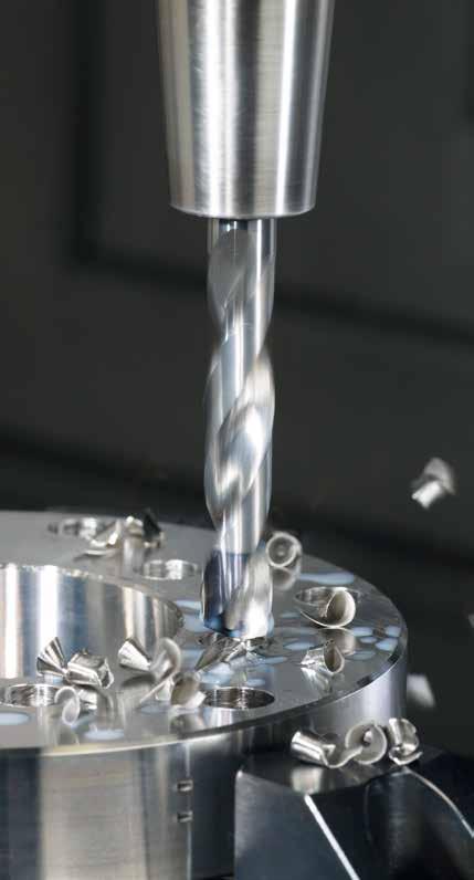
18 Product information Solid carbide drills Walter Titex X treme Step 90 Tip geometry for precise positioning With internal cooling Shank DIN 6535 HA XPL coating for optimum cutting data and tool life 4 lands for optimum hole quality and use on entry surfaces inclined up to 5 hole exits inclined up to 45 workpieces with cross holes Walter Titex X treme Step 90 Type: K3299XPL, HA shank, 3 x Dc The tool Solid carbide high-performance chamfer drill with and without internal cooling XPL coating Diameter range 3.3 to 14.5 mm Core hole diameter: M4 M16 x 1.5 mm Step length in accordance with DIN 8378 Shank in accordance with DIN 6535 HA and HE The application For thread/core hole diameters For ISO material groups P, M, K, N, S, H Can be used with emulsion and oil Can be used for inclined exits and cross holes Can be used for inclined and convex surfaces For use in general mechanical engineering, mould and die making, and the automotive and energy industries 16 Watch product video: Scan this QR code or go directly to Benefits for you 50% higher productivity Can be universally used for all material groups as well as for cross holes and inclined exits Improved hole quality thanks to the 4 lands
19 With internal cooling Walter Titex X treme Step 90 Types: K3899XPL, HE shank, 3 x Dc K3299XPL, HA shank, 3 x Dc K3879XPL, HE shank, 3 x Dc Module hinge Workpiece material: Cutting data St52 Tool: X treme Step 90 K3299XPL-M8 Diameter 6.8 mm Competition X treme Step 90 vc 98 m/min 98 m/min n 4600 rpm 4600 rpm f 0.16 mm/rev 0.23 mm/rev vf 736 mm/min 1058 mm/min Feed rate (mm/min) Competition % X treme Step
20 Product information Solid carbide drills Walter Titex X treme without internal cooling 4 lands for optimum hole quality and use on entry surfaces inclined up to 5 hole exits inclined up to 45 workpieces with cross holes Shank DIN 6535 HA Shank DIN 6535 HE Tip geometry for precise positioning XPL coating for extremely high-performance cutting data and extremely long tool life Walter Titex X treme Types: A3279XPL, HA shank, 3 x Dc A3879XPL, HE shank, 3 x Dc The tool Solid carbide high-performance drill with internal cooling XPL coating 140 point angle Dimensions to DIN 6537 K 3 x D c DIN 6537 L 5 x D c Diameter range 3 to 25 mm Shank in accordance with DIN 6535 HA and HE The application For all ISO material groups P, M, K, N, S, H Can be used with emulsion and oil Can be used for inclined exits and cross holes Can be used for inclined and convex surfaces For use in general mechanical engineering, mould and die making, and the automotive and energy industries 18 Watch product video: Scan this QR code or go directly to Benefits for you 50% higher productivity Can be universally used for all material groups as well as for cross holes and inclined exits Improved hole quality thanks to the 4 lands

21 4 lands for optimum hole quality and use on entry surfaces inclined up to 5 hole exits inclined up to 45 workpieces with cross holes Shank DIN 6535 HA Shank DIN 6535 HE XPL coating for extremely high-performance cutting data and extremely long tool life Tip geometry for precise positioning Walter Titex X treme Types: A3379XPL, HA shank, 5 x Dc A3979XPL, HE shank, 5 x Dc Magnetic core for controllers Workpiece material: Tool: Cutting data C15 X treme A3279XPL-12.5 Diameter 12.5 mm Previous X treme vc 122 m/min 122 m/min n 3107 rpm 3107 rpm f 0.23 mm/rev 0.23 mm/rev vf 715 mm/min 715 mm/min Tool life (m) Previous % 0 X treme
22 Product information Solid carbide drills Walter Titex X treme with internal cooling 4 lands for optimum hole quality and use on entry surfaces inclined up to 5 hole exits inclined up to 45 workpieces with cross holes Shank DIN 6535 HA Shank DIN 6535 HE With internal cooling XPL coating for extremely high-performance cutting data and extremely long tool life Tip geometry for precise positioning Walter Titex X treme Types: A3299XPL, HA shank, 3 x Dc A3899XPL, HE shank, 3 x Dc The tool Solid carbide high-performance drill with internal cooling XPL coating 140 point angle Dimensions to DIN 6537 K 3 x D c DIN 6537 L 5 x D c Diameter range 3 to 25 mm Shank in accordance with DIN 6535 HA and HE The application For all ISO material groups P, M, K, N, S, H Can be used with emulsion and oil Can be used for inclined exits and cross holes Can be used for inclined and convex surfaces For use in general mechanical engineering, mould and die making, and the automotive and energy industries Benefits for you 50% higher productivity Can be universally used for all material groups as well as for cross holes and inclined exits Improved hole quality thanks to the 4 lands 20
23 4 lands for optimum hole quality and use on entry surfaces inclined up to 5 hole exits inclined up to 45 workpieces with cross holes Shank DIN 6535 HA Shank DIN 6535 HE With internal cooling XPL coating for extremely high-performance cutting data and extremely long tool life Tip geometry for precise positioning Walter Titex X treme Types: A3399XPL, HA shank, 5 x Dc A3999XPL, HE shank, 5 x Dc Transmission shaft: Flange drilling Workpiece material: 42CrMo4 Tool: X treme A3399XPL-6.8 Diameter 6.8 mm Cutting data Previous X treme vc 56 m/min 91 m/min n 2621 rpm 4260 rpm f 0.11 mm/rev 0.19 mm/rev vf 288 mm/min 809 mm/min Feed rate (mm/min) Watch product video: Scan this QR code or go directly to % Previous 288 X treme
24 Product information Solid carbide drills Walter Titex X treme Plus DPL coating for maximum productivity Shank DIN 6535 HA With internal cooling Improved flute profile for reliable chip removal at high cutting speeds Tip geometry Optimised for extremely high cutting speeds Walter Titex X treme Plus Types: A3289DPL, HA shank, 3 x Dc A3389DPL, HA shank, 5 x Dc The tool Solid carbide high performance drill with internal coolant supply New type of multifunctional double coating (DPL: Double Performance Line ) 140 point angle Dimensions in accordance with DIN 6537 K 3 x D c DIN 6537 L 5 x D c Diameter range 3 to 20 mm Shank according to DIN 6535 HA The application For all ISO material groups P, M, K, S, H (N) Can be used with emulsion, oil and minimum quantity lubrication For use in general mechanical engineering, in mould and die making, and the automotive and energy industries 22
25 Benefits for you Maximum productivity: At least double that achievable using conventional tools (greater productivity, lower production costs) Alternatively: Double the tool life with conventional cutting data (e.g. fewer tool changes) Excellent surface finish High process reliability Varied application possibilities with regard to materials and application (e.g. MQL) Ensures spare machine capacity With this tool, Walter Titex is setting new standards in drilling with solid carbide tools. The drill incorporates a wealth of innovations including the new multifunctional double coating (DPL) that has outstanding properties. With Walter Titex X treme Plus you can increase productivity in the series production of steel components. Workpiece Chip Tip coating Basic coating Carbide Example Workpiece material: Tool: 42CrMo4 X treme Plus A3389DPL-8.5 Diameter 8.5 mm Speed + 200% Competition X treme Plus vf 390 mm/min 1460 mm/min Tool life 38 parts 63 parts Costs - 50% Tool life (parts) Competition % Cost savings and increases in productivity with the X treme Plus X treme Plus
26 Product information Solid carbide drills Walter Titex X treme CI Flutes designed for optimum chip removal Tip geometry with internal coolant supply for extremely long tool life Shank DIN 6535 HA XPL coating for optimum cutting data and maximum tool life Facet for optimum hole quality and high process reliability for extremely long tool life Walter Titex X treme CI Type: A3382XPL, HA shank, 5 x Dc The tool Solid carbide high-performance drill with internal cooling XPL coating 140 point angle Dimensions according to DIN 6537 L 5 x D c Diameter range 3 to 20 mm Shank according to DIN 6535 HA The application For ISO material group K Can be used with emulsion, oil, minimum quantity lubrication and dry machining For use in general mechanical engineering, in mould and die making, and in the automotive and energy industries 24
27 Benefits for you Increase in productivity thanks to 50% higher workpiece values in comparison with conventional solid carbide drills Optimum hole quality for blind holes and through holes thanks to special facet no chipping at the hole exit High process reliability thanks to very even wear behaviour when machining cast iron materials Bearing cap: Drilling of flange holes Workpiece material: Tool: Drilling depth: GJS 400 X treme CI A3382XPL-18.5 Diameter 18.5 mm 60 mm Cutting data X treme CI vc n f vf 120 m/min 2065 rpm 0.5 mm 1032 mm/min Flank face wear after 310 m drill travel X treme CI % Previously
28 Product information Solid carbide drills Walter Titex X treme Inox Land for optimum hole quality and low friction Shank DIN 6535 HA Flute geometry ensures reliable chip evacuation and guarantees process reliability TTP coating for optimum cutting data and a maximum increase in productivity Walter Titex X treme Inox Type: A3393TTP, HA shank, 5 x Dc The tool Solid carbide high-performance drill TTP coating Dimensions to DIN 6537 K 3 x D c DIN 6537 L 5 x D c Diameter range 3 to 20 mm Shank according to DIN 6535 HA The application For ISO material group M Can be used with emulsion and oil For use in general mechanical engineering and in the automotive, aerospace, medical, food and valve industries Benefits for you Reduced cutting forces due to new type of geometry Significant increase in productivity over universal drilling tools Low burr formation on entry and exit Excellent surface quality on component Stable main cutting edges guarantee maximum process reliability 26

29 Tip geometry for reduced cutting forces, low burr formation and stable cutting edges High-pressure rail for fleece compressor Workpiece material: Tool: X treme Inox A3393TTP-14.2 Diameter 14.2 mm Cutting data Competition X treme Inox vc 60 m/min 70 m/min n 1345 rpm 1570 rpm f 0.2 mm/rev 0.3 mm/rev vf 269 mm/min 471 mm/min Tool life (m) Competition % X treme Inox Feed rate (mm/min) Competition % Watch product video: Scan this QR code or go directly to X treme Inox

30 Product information Solid carbide drills Walter Titex X treme M, DM8..30 X treme Pilot 150 X treme M Watch product video: Scan this QR code or go directly to X treme DM8 X treme DM12 X treme DM16 X treme DM20 X treme DM25 X treme DM30 28
31 The tool Solid carbide high-performance drill with internal cooling AML coating (AlTiN) AMP coating (AlTiN tip coating) Available in the following sizes: 2 x D c X treme Pilot x D c X treme M 8 x D c X treme DM8 12 x D c X treme DM12 16 x D c X treme DM16 20 x D c X treme DM20 25 x D c X treme DM25 30 x D c X treme DM30 Diameter range 2 to 2.95 mm Shank according to DIN 6535 HA The application ISO material groups P, M, K, N, S, H, O Drilling with emulsion and oil For use in general mechanical engineering, mould and die making, and the automotive and energy industries Benefits for you Measurable increases in productivity due to machining values which are up to 50% higher than conventional solid carbide micro-drills New types of point and flute geometry ensure high process reliability Polished flutes ensure reliable chip evacuation Demo component Workpiece material: Tool: X treme DM12 A6589AMP-2 Diameter 2 mm Cutting data Previous X treme DM12 vc 50 m/min 60 m/min n 7960 rpm 9550 rpm f 0.04 mm/rev 0.06 mm/rev vf 320 mm/min 573 mm/min Feed rate (mm/min) Previous % X treme DM Number of holes Previous % X treme DM
32 Product information Solid carbide drills Walter Titex X treme Pilot Step countersink angle for guiding in the solid carbide deep-hole drill for deburring or chamfering the hole Piloting with chamfer Shank DIN 6535 HA TFT coating for optimum protection against wear Tip geometry with a 150 point angle for optimum centring of the solid carbide deep-hole drill Walter Titex X treme Pilot Step 90 Type: K3281TFT, HA shank, 2 x Dc The tool Solid carbide high-performance chamfering pilot drill with internal cooling TFT coating 150 point angle 90 countersink angle Dimensions according to Walter standard Drilling depth 2 x D c Diameter range 3 to 16 mm Shank according to DIN 6535 HA The application For the ISO material groups P, M, K, N, S, H Step pilot drill for solid carbide deep-hole drills from the Alpha and X treme drill families for drilling depths of approx. 12 x D c Can be used with emulsion and oil For use in general mechanical engineering, in the hydraulic industry, in mould and die making, and in the automotive and energy industries 30
33 Other Walter Titex pilot drills Cylindrical piloting Type: A6181TFT Cylindrical piloting Type: A6181AML Cylindrical piloting Type: A7191TFT Conical piloting Type: K5191TFT Benefits for you Higher process reliability and tool life in deep-hole drilling Significantly reduced hole run-off No tolerance overlaps with solid carbide deep-hole drills High positioning accuracy as a result of a short chisel edge width 31
34 Product information Solid carbide drills Walter Titex XD70 Technology Coating TTP tip coating Polished flute for reliable chip evacuation 4 lands for optimum hole quality and use on: inclined hole exits workpieces with cross holes The tool Solid carbide high-performance drill with internal cooling TTP tip coating Dimensions: Up to 50 x D c as a standard tool x D c as a special tool Diameter range 4.5 to 12 mm Shank according to DIN 6535 HA The application For the ISO material groups P, K, N (M, S) Can be used with emulsion and oil For use in general mechanical engineering, mould and die making, and the automotive and energy industries Piston rod Workpiece material: St 52-3 Tool: Diameter 7 mm Drilling depth: 450 mm 65 x D c Cutting data Previous Gun drill XD70 technology v c 70 m/min 70 m/min n 3185 rpm 3185 rpm f 0.03 mm/rev 0.15 mm/rev v f 95 mm/min 478 mm/min Tool life 12 components 50 components Feed rate Previous % XD70 technology Tool life: Number of components Previous % XD70 technology


35 70 x D c as special tool Standard range X treme D50 50 x D c X treme D40 40 x D c Alpha 4 XD30 30 x D c Alpha 4 XD25 25 x D c Benefits for you Up to 10-times higher productivity than gun drills Drilling without pecking Maximum process reliability at deep drilling depths Suitable for use with low coolant pressures from 20 bar Can be used with various material groups such as ISO P, K, N (M, S) Can be used for cross holes and inclined exits Watch product video: Scan this QR code or go directly to Alpha 4 XD20 20 x D c Alpha 4 XD16 16 x D c Watch product animation: Scan this QR code or go directly to 33
36 Product information Walter Select Walter Select for carbide and HSS drilling tools Step by step to the right tool Step 1 Define the material to be machined, see GK page H 8 onwards. Note the machining group that corresponds to your material e.g.: K5. Identification letters Machining group P P1 P15 Steel M M1 M3 Stainless steel K K1 K7 Cast iron Groups of the materials to be machined All types of steel and cast steel, with the exception of steel with an austenitic structure Stainless austenitic steel, austenitic-ferritic steel and cast steel Grey cast iron, cast iron with spheroidal graphite, malleable cast iron, cast iron with vermicular graphite N N1 N10 NF metals Aluminium and other nonferrous metals, non-ferrous materials S S1 S10 Super alloys and titanium alloys Heat-resistant special alloys based on iron, nickel and cobalt, titanium and titanium alloys H H1 H4 Hard materials Hardened steel, hardened cast iron materials, chilled cast iron O O1 O6 Other Plastics, glass- and carbonfibre reinforced plastics, graphite STEP 2 Select the machining conditions: Machine stability, clamping system and workpiece very good good moderate a b c Step 3 Select the cutting material (HSS, carbide) and the type of cooling: Tools made from carbide with internal cooling: from page GK B 16 Tools made from carbide without internal cooling: from page GK B 22 Tools made from HSS: from page GK B 26 Page information refers to: HB = this handbook GK = Walter General Catalogue 2012 EK = Walter Supplementary Catalogue 2013/
37 Step 4 Choose your tool: In accordance with the drilling depth or DIN (e.g. 3 x D c or DIN 338) In accordance with machining conditions (see step 2: Walter Select Drilling Solid carbide drills with internal cooling Material group Walter Select Drilling Solid carbide drills with internal cooling Material group austenitic, duplex M Stainless steel Fe-based Cutting Heat-resistant data alloys for solid carbide austenitic, Ni or Co base precipitation drills with hardened internal (PH) 250cooling S1, C 1010 C M1, M3 C C M2 C C C C C C S2 C S3 C Ni or Co base S4, S5 C C C Grey cast iron 245 K3, K4 C C pure titanium S6 C C C C Cast iron with S spheroidal Drilling depth 3 x Dc Titanium = cutting alloysgraphite data for wet machining ferritic, α and β alloys, pearlitic hardened S7 C C K1, K2, C CK5, K6 C C A3285TFL GGV (CGI) = dry machining is possible, cutting data β must alloys be selected from TEC Designation200 S8 A3289DPL C C K7 C C C C A3885TFL Tungsten E = Emulsion alloys S9 C C Molybdenum O = Oil alloys cannot be hardened Type 30 S10 X treme PlusC Alpha N1 C4 C Aluminium wrought alloys M = MQL Dimensions DIN 6537 K DIN 6537 K hardenable, hardened 50 HRC 100 H1 340C C N2 C C C L = dry Dia. range (mm) 3,00 20,00 3,00 20,00 H Hardened steel 55 HRC H2, H4 C C v C = cutting speed 12 % Si Cutting tool material K30F K30F 60 HRC 90 H3 310 N3, N4 C Cast aluminium VCRR alloys = v c rating chart from page B 382 Coating DPL TFL Thermoplasts VRR = feed rating chart from page B > without 12 % abrasive Si fillers Page 130 O1 B 450C 70 B 66 / B N5 C Thermosetting plastics without abrasive fillers O2 Magnesium alloys N6 O GFRP, AFRP O3, O5 Fibre-reinforced plastic non-alloyed, CFRP electrolytic copper 100 O4 340 N7 C Graphite (technical) 65 O6 Copper and copper alloys brass, bronze, red brass N8 C Grouping of main material groups (bronze/brass) and identification Cu-alloys, short-chipping letters N9 C high-strength, Ampco N10 C C Fe-based S1, S2 C C Heat-resistant alloys Ni or Co base S3 C C Workpiece material Ni Co base S4, S5 C vc VRR vc VRR C 0.25 % annealed P E O M L E O M L B 16 pure titanium S6 C C C > % annealed P E O M L E O M L Titanium alloys α C > and β alloys, 0.55 % hardened tempered P E O M L S7 E O M L C C Non-alloyed steel C > 0.55 % annealed P E O M L E O M L β alloys S8 C C C > 0.55 % tempered P E O M L 75 9 E O M L Tungsten alloys machining steel (short-chipping) annealed P E O M L S9 E O M L C annealed P E O M L E O M L Molybdenum Palloys tempered P E O M L 75 9 S10 E O M L C Low alloy steel tempered P O E 50 6 O E 50 HRC H1 C C tempered P O E 42 4 O E Hardened steel annealed HRC P E O 67 9 H2, E OH4 C High-alloyed steel and hardened and tempered P E O 60 7 E O high-alloyed tool steel hardened and tempered HRC P O E 42 4 H3 O E ferritic/martensitic, annealed P E O 67 9 E O Thermoplasts Stainless steel without abrasive fillers O1 C martensitic, tempered P E O 42 7 E O Thermosetting plastics without austenitic, quench abrasive hardened fillers M E O 42 5 O2 E O M Stainless steel austenitic, precipitation hardened (PH) M E O 56 6 E O GFRP, austenitic/ferritic, AFRP duplex M E O 34 5 O3, E OO5 Fibre-reinforced plastic ferritic K E O M L E O M L Malleable cast iron CFRP O4 260 M L Graphite (technical) 65 O6 gr K Material group Non-alloyed and low alloy steel Machine stability, clamping system and workpiece very good good moderate Grouping of main material groups and identification letters Workpiece material C C Main application C Additional application Brinell hardness HB Brinell hardness HB Tensile strength R m N/mm 2 Machining group 1 Drilling Machining conditions 3 x Dc Drilling depth Machining conditions a b Designation A3289DPL A3285TFL Designation A3289DPL A3885TFL TypeX treme X treme Plus Type Plus Alpha 4 Dimensions DIN 6537 K Dimensions DIN 6537 K DIN 6537 K Dia. range (mm) 3,00 20,00 3,00 20,00 Cutting tool material range K30F(mm) K30F Dia. 3,00 20,00 Coating DPL Cutting tool material TFL K30F Page B B 66 / B Coating DPL B Page Grouping of main material groups and identification letters annealed (tempered) P1, P2, P3, P4, P7 C C C C machining steel Workpiece material P6 C C C C tempered P5, P8 C C C C tempered P9 C C C C tempered P10 C C C C P annealed P11 C C C C High-alloyed steel and hardened and tempered P12 C C C C high-alloyed tool steel hardened and tempered P13 C C C C ferritic/martensitic, annealed P14 C C C C annealed martensitic, tempered (tempered) P15 700C C P3, C C P1, P2, P4, P7 C C Stainless steel machining austenitic, duplex steel M1, M3 750C C P6 C C C C M Stainless steel Non-alloyed and low austenitic, precipitation hardened (PH) M2 C C C C tempered 1010 P5, P8 300 C C K3, C C C Grey cast iron 245 K4 C alloy steel K tempered ferritic, pearlitic 380 K1, K2, 1280 C P9 C C C C Cast iron with spheroidal graphite 365 K5, K6 C GGV (CGI) 200 K7 C tempered P10 C C C C C cannot be hardened C 30 N1 Aluminium wrought alloys annealed hardenable, hardened C P11 C C N2 High-alloyed steel and hardened N P12 12 % Si and tempered N3, C C C C Cast aluminium alloys high-alloyed tool steel > 12 % Si N5 C C C N hardened and tempered P13 C C Magnesium alloys N6 ferritic/martensitic, annealed N7 670 P14 non-alloyed, electrolytic copper 200 C C C C C Stainless steel brass, bronze, red brass N8 C C C Copper and copper alloys (bronze/brass) martensitic, Cu-alloys, short-chipping tempered C P15 C C C C N9 a b c) For the relevant machining P group (see step 1: P1 15; M1 M3;... O1 O6) Step 5 Choose your cutting data from the table. See GK page B 352 or HB K N page 36 onwards: Cutting speed: S v c ; VCRR (v c rate chart for micro) Feed: VRR H (feed rate chart) O Machine stability, clamping system and workpiece very good good moderate C C Main application C Additional application high-strength, Ampco N10 C C C C Tensile strength R m N/mm² Brinell hardness HB Machining group Drilling depth Tensile strength R m N/mm² Machining group a 3 x Aluminium wrought alloys cannot be hardened 30 N E O M hardenable, hardened N E O M Go to the row of your machining group (e.g. K5) and the column of 12 % Si, not precipitation hardenable N E O M E O M Cast aluminium alloys 12 % Si, precipitation hardenable, precipitation hardened N E O M E O M > 12 % Si, not precipitation hardenable N Magnesium alloys your selected drilling tool. You will find the non-alloyed, cutting electrolytic copper speed v c or 100 the 343 N E O M E O M N M L M L N M M E O E O VCRR and VRR there. brass, bronze, red brass N E O E O Copper and copper alloys (bronze/brass) Cu-alloys, short-chipping N E O M E O M high-strength, Ampco N E O 60 7 E O S E O 42 5 E O annealed Fe-based B 16 hardened S O E 26 4 O E 5 E O 32 4 E O Heat-resistant alloys annealed S3 42 Ni or Co base hardened S4 26 The v c rate chart (VCRR) and the feed rate chart (VRR) cast can 320 be 1076 found S5 32 S 4 O E 16 3 O E 4 O E 20 3 O E pure titanium S O E 56 6 O E Titanium alloys α and β alloys, hardened S O E 48 5 O E β alloys S O E 12 3 O E in the GK from page B 382 or in the EK from page B-122 onwards. H O Tungsten alloys S E O 60 7 E O Molybdenum alloys S E O 60 7 E O Hardened steel hardened and tempered 50 HRC H O E 36 3 O E hardened and tempered 55 HRC H O E 31 3 O E hardened and tempered 60 HRC H3 Hardened cast iron hardened and tempered 55 HRC H O E 31 3 O E Thermoplasts without abrasive fillers O E O Thermosetting plastics without abrasive fillers O2 Plastic, glass-fibre reinforced GFRP O3 Plastic, carbon fibre reinforced CFRP O4 Plastic, aramide fibre reinforced AFRP O5 Graphite (technical) O6 80 Shore 1 The machining groups are assigned from page H 8 onwards. 35
38 Product information Cutting data Solid carbide cutting data with internal cooling (part 1/8) Material group P 36 Non-alloyed steel Low-alloyed steel High-alloyed steel and high-alloyed tool steel Stainless steel M Stainless steel K N S E = Emulsion O = Oil M = MQL L = Dry = Cutting data for wet machining = Dry machining is possible, cutting data must be selected from Walter GPS Malleable cast iron Grey cast iron Structure of main material groups and code letters Workpiece material Drilling depth Designation Type Dimensions Ø range (mm) Cutting material Coating Page Brinell hardness HB Tensile strength R m N/mm 2 Machining group 1 C 0.25% Annealed P1 C > % Annealed P2 C > % Tempered P3 C > 0.55% Annealed P4 C > 0.55% Tempered P5 Free cutting steel (short-chipping) Annealed P6 Annealed P7 Tempered P8 Tempered P9 Tempered P10 Annealed P11 Hardened and tempered P12 Hardened and tempered P13 Ferritic/martensitic, annealed P14 Martensitic, tempered P15 Austenitic, quench hardened M1 Austenitic, precipitation hardened (PH) M2 Austenitic/ferritic, duplex M3 Ferritic K1 Pearlitic K2 Low tensile strength K3 High tensile strength/austenitic K4 Ferritic K5 Pearlitic K6 Cast iron with spheroidal graphite GGV (CGI) K7 Aluminium wrought alloys Cannot be hardened 30 N1 Hardenable, hardened N2 12% Si, cannot be hardened N3 Cast aluminium alloys 12% Si, hardenable, hardened N4 > 12% Si, cannot be hardened N5 Magnesium alloys N6 Copper and copper alloys (bronze/brass) Heat-resistant alloys Titanium alloys v C = Cutting speed VCRR = v c rate chart HB page 54 VRR = feed rate chart HB page 55 Non-alloyed, electrolytic copper N7 Brass, bronze, red brass N8 Cu-alloys, short-chipping N9 High-strength, Ampco N10 Fe-based Annealed S1 Hardened S2 Annealed S3 Ni or Co base Hardened S4 Cast S5 Pure titanium S6 α and β alloys, hardened S7 β alloys S8 Tungsten alloys S9 Molybdenum alloys S10 H Hardened and tempered 55 HRC H2 Hardened and tempered 60 HRC H3 Hardened steel Hardened and tempered 50 HRC H1 Hardened cast iron Hardened and tempered 55 HRC H4 Thermoplastics Without abrasive fillers O1 Thermosetting plastics Without abrasive fillers O2 Plastic, glass-fibre reinforced GFRP O3 O Plastic, carbon-fibre reinforced CFRP O4 Plastic, aramid-fibre reinforced AFRP O5 Graphite (technical) 80 Shore O6 Page information refers to:
39 The specified cutting data are average recommended values. For special applications, adjustment is recommended. 3 x D c K3299XPL K3899XPL A3289DPL A3293TTP A3299XPL A3899XPL X treme Step 90 X treme Plus X treme Inox X treme Walter standard DIN 6537 K DIN 6537 K DIN 6537 K K30F K30F K30F K30F XPL DPL TTP XPL EK B-75 / B-77 GK B 70 EK B-30 EK B-33 / B-54 v c VRR v c VRR v c VRR v c VRR E O M L E O M L E O M L E O M L E O M L E O M L E O M L E O M L E O M L E O M L E O M L E O M L E O M L E O M L E O M L E O M L E O M L E O M L E O M L E O M L E O M L E O M L E O M L E O M L E O M L E O M L E O M L E O M L E O M L E O M L 80 7 O E O E 80 7 O E 63 5 O E 80 6 O E 63 5 O E 71 9 E O 85 9 E O 71 9 E O 95 9 E O E O 95 9 E O 63 5 O E 80 6 O E 63 5 O E 71 9 E O 85 9 E O 95 9 E O 71 9 E O 40 8 E O 50 9 E O 55 8 E O 40 8 E O 40 6 E O 50 6 E O 53 6 E O 40 6 E O 45 6 E O 63 6 E O 68 6 E O 45 6 E O 34 5 E O 40 6 E O 53 6 E O 34 5 E O E O M L E O M L E O M L E O M L E O M L E O M L E O M L E O M L E O M L E O M L E O M L E O M L E O M L E M L E O M L E O M L E O M L E O M L E O M L O E M L E O M L E O M E O M E O M E O M E O M E O M E O M E O M E O M E O M E O M E O M E O M E O M E O M E O M E O M E O M E O M E O M M L M L M L M L E O M E O M E O M E O M E O E O E O E O E O M E O M E O M E O M 60 5 E O E O 60 7 E O 60 5 E O 50 6 E O 50 6 E O 50 6 E O 50 6 E O 30 5 O E 38 5 O E 38 5 O E 30 5 O E 34 5 E O 42 5 E O 42 5 E O 34 5 E O 19 4 O E 26 4 O E 26 4 O E 19 4 O E 26 4 O E 32 4 O E 32 4 O E 26 4 O E 56 6 O E 71 6 O E 71 6 O E 56 6 O E 50 5 O E 63 5 O E 63 5 O E 50 5 O E 12,5 4 O E 20 4 O E 20 4 O E 12,5 4 O E 60 5 E O E O E O 60 5 E O 60 5 E O E O E O 60 5 E O 48 4 O E 53 4 O E 48 4 O E 32 3 O E 45 4 O E 32 3 O E 32 3 O E 45 4 O E 32 3 O E E O E O E O E O HB = this handbook GK = Walter General Catalogue 2012 EK = Walter Supplementary Catalogue 2013/
40 Product information Cutting data Solid carbide cutting data with internal cooling (part 2/8) Material group P 38 Non-alloyed steel Low-alloyed steel High-alloyed steel and high-alloyed tool steel Stainless steel M Stainless steel K N S E = Emulsion O = Oil M = MQL L = Dry = Cutting data for wet machining = Dry machining is possible, cutting data must be selected from Walter GPS Malleable cast iron Grey cast iron Structure of main material groups and code letters Workpiece material Drilling depth Designation Type Dimensions Ø range (mm) Cutting material Coating Page Brinell hardness HB Tensile strength R m N/mm 2 Machining group 1 C 0.25% Annealed P1 C > % Annealed P2 C > % Tempered P3 C > 0.55% Annealed P4 C > 0.55% Tempered P5 Free cutting steel (short-chipping) Annealed P6 Annealed P7 Tempered P8 Tempered P9 Tempered P10 Annealed P11 Hardened and tempered P12 Hardened and tempered P13 Ferritic/martensitic, annealed P14 Martensitic, tempered P15 Austenitic, quench hardened M1 Austenitic, precipitation hardened (PH) M2 Austenitic/ferritic, duplex M3 Ferritic K1 Pearlitic K2 Low tensile strength K3 High tensile strength/austenitic K4 Ferritic K5 Pearlitic K6 Cast iron with spheroidal graphite GGV (CGI) K7 Aluminium wrought alloys Cannot be hardened 30 N1 Hardenable, hardened N2 12% Si, cannot be hardened N3 Cast aluminium alloys 12% Si, hardenable, hardened N4 > 12% Si, cannot be hardened N5 Magnesium alloys N6 Copper and copper alloys (bronze/brass) Heat-resistant alloys Titanium alloys v C = Cutting speed VCRR = v c rate chart HB page 54 VRR = feed rate chart HB page 55 Non-alloyed, electrolytic copper N7 Brass, bronze, red brass N8 Cu-alloys, short-chipping N9 High-strength, Ampco N10 Fe-based Annealed S1 Hardened S2 Annealed S3 Ni or Co base Hardened S4 Cast S5 Pure titanium S6 α and β alloys, hardened S7 β alloys S8 Tungsten alloys S9 Molybdenum alloys S10 H Hardened and tempered 55 HRC H2 Hardened and tempered 60 HRC H3 Hardened steel Hardened and tempered 50 HRC H1 Hardened cast iron Hardened and tempered 55 HRC H4 Thermoplastics Without abrasive fillers O1 Thermosetting plastics Without abrasive fillers O2 Plastic, glass-fibre reinforced GFRP O3 O Plastic, carbon-fibre reinforced CFRP O4 Plastic, aramid-fibre reinforced AFRP O5 Graphite (technical) 80 Shore O6 Page information refers to:
41 The specified cutting data are average recommended values. For special applications, adjustment is recommended. 5 x D c A3389AML A3389DPL A3393TTP A3382XPL X treme M X treme Plus X treme Inox X treme CI Walter standard DIN 6537 L DIN 6537 L DIN 6537 L K30F K30F K30F K30F AML DPL TTP XPL EK B-41 GK B 86 EK B-42 GK B 81 VCRR VRR v c VRR v c VRR v c VRR C E E O M L E O M L C80 12 E E O M L E O M L C80 12 E E O M L E O M L C E E O M L E O M L C71 12 E E O M L C E E O M L E O M L C80 12 E E O M L E O M L C71 12 E E O M L C56 9 E 95 8 O E C40 6 E 71 6 O E C63 10 E 85 9 E O C63 12 E E O C40 6 E 71 6 O E C63 10 E 85 9 E O 90 9 E O C50 8 E 48 9 E O 50 8 E O C40 8 E 48 6 E O 50 6 E O C63 10 E 60 6 E O 65 6 E O C32 5 E 38 6 E O 50 6 E O C E E O M L E O M L C E E O M L E O M L C E E O M L E O M L C E E O M L E O M L C E E M L E O M L C E E O M L E O M L C E O E M L E O M L C E E O M E O M C E E O M E O M C E E O M E O M C E E O M E O M C E E O M E O M M L M L C100 6 E E O M E O M C80 12 E E O E O C E E O M E O M C56 8 E E O 60 7 E O C50 8 E 48 6 E O 48 6 E O C26 6 E 36 5 O E 36 5 O E C32 5 E 40 5 E O 40 5 E O C16 6 E 24 4 O E 24 4 O E C16 6 E 30 4 O E 30 4 O E C50 6 E 60 6 O E 60 6 O E C32 5 E 53 5 O E 53 5 O E C16 5 E 18 4 O E 18 4 O E C56 8 E E O E O C56 8 E E O E O C32 3 E 53 4 O E C32 3 E 45 4 O E C32 3 E 45 4 O E C E E O E O HB = this handbook GK = Walter General Catalogue 2012 EK = Walter Supplementary Catalogue 2013/
42 Product information Cutting data Solid carbide cutting data with internal cooling (part 3/8) Material group P 40 Non-alloyed steel Low-alloyed steel High-alloyed steel and high-alloyed tool steel Stainless steel M Stainless steel K N S E = Emulsion O = Oil M = MQL L = Dry = Cutting data for wet machining = Dry machining is possible, cutting data must be selected from Walter GPS Malleable cast iron Grey cast iron Structure of main material groups and code letters Workpiece material Drilling depth Designation Type Dimensions Ø range (mm) Cutting material Coating Page Brinell hardness HB Tensile strength R m N/mm 2 Machining group 1 C 0.25% Annealed P1 C > % Annealed P2 C > % Tempered P3 C > 0.55% Annealed P4 C > 0.55% Tempered P5 Free cutting steel (short-chipping) Annealed P6 Annealed P7 Tempered P8 Tempered P9 Tempered P10 Annealed P11 Hardened and tempered P12 Hardened and tempered P13 Ferritic/martensitic, annealed P14 Martensitic, tempered P15 Austenitic, quench hardened M1 Austenitic, precipitation hardened (PH) M2 Austenitic/ferritic, duplex M3 Ferritic K1 Pearlitic K2 Low tensile strength K3 High tensile strength/austenitic K4 Ferritic K5 Pearlitic K6 Cast iron with spheroidal graphite GGV (CGI) K7 Aluminium wrought alloys Cannot be hardened 30 N1 Hardenable, hardened N2 12% Si, cannot be hardened N3 Cast aluminium alloys 12% Si, hardenable, hardened N4 > 12% Si, cannot be hardened N5 Magnesium alloys N6 Copper and copper alloys (bronze/brass) Heat-resistant alloys Titanium alloys v C = Cutting speed VCRR = v c rate chart HB page 54 VRR = feed rate chart HB page 55 Non-alloyed, electrolytic copper N7 Brass, bronze, red brass N8 Cu-alloys, short-chipping N9 High-strength, Ampco N10 Fe-based Annealed S1 Hardened S2 Annealed S3 Ni or Co base Hardened S4 Cast S5 Pure titanium S6 α and β alloys, hardened S7 β alloys S8 Tungsten alloys S9 Molybdenum alloys S10 H Hardened and tempered 55 HRC H2 Hardened and tempered 60 HRC H3 Hardened steel Hardened and tempered 50 HRC H1 Hardened cast iron Hardened and tempered 55 HRC H4 Thermoplastics Without abrasive fillers O1 Thermosetting plastics Without abrasive fillers O2 Plastic, glass-fibre reinforced GFRP O3 O Plastic, carbon-fibre reinforced CFRP O4 Plastic, aramid-fibre reinforced AFRP O5 Graphite (technical) 80 Shore O6 Page information refers to:
43 The specified cutting data are average recommended values. For special applications, adjustment is recommended. 5 x D c 8 x D c 12 x D c A3399XPL A3999XPL A6489AMP A6489DPP A6589AMP X treme X treme DM8 X treme D8 X treme DM12 DIN 6537 L Walter standard Walter standard Walter standard K30F K30F K30F K30F XPL AMP DPP AMP GK B 89 / B 112 EK B-67 GK B 123 EK B-68 v c VRR VCRR VRR v c VRR VCRR VRR E O M L C E E O M L C80 12 E E O M L C80 12 E E O M L C80 12 E E O M L C80 12 E E O M L C80 12 E E O M L C80 12 E E O M L C80 12 E 71 8 E O M L C71 12 E E O M L C59 10 E E O M L C E E O M L C80 12 E E O M L C80 12 E E O M L C80 12 E 71 8 E O M L C71 12 E E O M L C59 10 E 48 6 O E C53 8 E 85 7 O E C45 7 E 38 4 O E C40 6 E 63 5 O E C40 6 E 63 8 E O C63 10 E 80 8 E O C63 10 E 56 7 E O C63 10 E E O C50 8 E 38 4 O E C40 6 E 63 5 O E C40 6 E 63 8 E O C63 10 E 80 8 E O C63 10 E 42 7 E O C50 8 E 45 8 E O C50 8 E 38 5 E O C40 8 E 45 6 E O C40 7 E 42 6 E O C50 8 E 56 6 E O C50 7 E 31 5 E O C32 5 E 36 6 E O C25 5 E E O M L C E E O M L C E E O M L C E E O M L C E E O M L C E E O M L C E E O M L C E E O M L C E E O M L C E E O M L C E E O M L C E E O M L C80 11 E E O M L C E E O M L C E E O M C E E O M C E E O M C E E O M C E E O M C E E O M C E E O M C E E O M C E E O M C E E O M C E M L M L E O M C80 6 E E O M C80 6 E E O C80 12 E E O C80 11 E E O M C E E O M C80 19 E 56 7 E O C52 8 E E O C50 7 E 42 5 E O C40 8 E 45 6 E O C40 7 E 24 4 O E C24 6 E 32 5 O E C21 6 E 30 4 E O C32 5 E 38 5 E O C25 5 E 15 3 O E C16 6 E 21 4 O E C16 5 E 18 3 O E C16 6 E 26 4 O E C16 5 E 48 6 O E C50 6 E 50 5 O E C40 6 E 40 5 O E C32 5 E 45 5 O E C32 5 E 11 3 O E C16 5 E 16 4 O E C16 5 E 56 7 E O C52 8 E E O C56 8 E 56 7 E O C52 8 E E O C56 8 E 30 3 O E C32 3 E 45 3 O E C32 3 E 26 3 O E C32 3 E 38 3 O E C32 3 E 26 3 O E C32 3 E 38 3 O E C32 3 E C E E O C E HB = this handbook GK = Walter General Catalogue 2012 EK = Walter Supplementary Catalogue 2013/
44 Product information Cutting data Solid carbide cutting data with internal cooling (part 4/8) Material group P 42 Non-alloyed steel Low-alloyed steel High-alloyed steel and high-alloyed tool steel Stainless steel M Stainless steel K N S E = Emulsion O = Oil M = MQL L = Dry = Cutting data for wet machining = Dry machining is possible, cutting data must be selected from Walter GPS Malleable cast iron Grey cast iron Structure of main material groups and code letters Workpiece material Drilling depth Designation Type Dimensions Ø range (mm) Cutting material Coating Page Brinell hardness HB Tensile strength R m N/mm 2 Machining group 1 C 0.25% Annealed P1 C > % Annealed P2 C > % Tempered P3 C > 0.55% Annealed P4 C > 0.55% Tempered P5 Free cutting steel (short-chipping) Annealed P6 Annealed P7 Tempered P8 Tempered P9 Tempered P10 Annealed P11 Hardened and tempered P12 Hardened and tempered P13 Ferritic/martensitic, annealed P14 Martensitic, tempered P15 Austenitic, quench hardened M1 Austenitic, precipitation hardened (PH) M2 Austenitic/ferritic, duplex M3 Ferritic K1 Pearlitic K2 Low tensile strength K3 High tensile strength/austenitic K4 Ferritic K5 Pearlitic K6 Cast iron with spheroidal graphite GGV (CGI) K7 Aluminium wrought alloys Cannot be hardened 30 N1 Hardenable, hardened N2 12% Si, cannot be hardened N3 Cast aluminium alloys 12% Si, hardenable, hardened N4 > 12% Si, cannot be hardened N5 Magnesium alloys N6 Copper and copper alloys (bronze/brass) Heat-resistant alloys Titanium alloys v C = Cutting speed VCRR = v c rating chart HB page 54 VRR = feed rate chart HB page 55 Non-alloyed, electrolytic copper N7 Brass, bronze, red brass N8 Cu-alloys, short-chipping N9 High-strength, Ampco N10 Fe-based Annealed S1 Hardened S2 Annealed S3 Ni or Co base Hardened S4 Cast S5 Pure titanium S6 α and β alloys, hardened S7 β alloys S8 Tungsten alloys S9 Molybdenum alloys S10 H Hardened and tempered 55 HRC H2 Hardened and tempered 60 HRC H3 Hardened steel Hardened and tempered 50 HRC H1 Hardened cast iron Hardened and tempered 55 HRC H4 Thermoplastics Without abrasive fillers O1 Thermosetting plastics Without abrasive fillers O2 Plastic, glass-fibre reinforced GFRP O3 O Plastic, carbon-fibre reinforced CFRP O4 Plastic, aramid-fibre reinforced AFRP O5 Graphite (technical) 80 Shore O6 Page information refers to:
45 The specified cutting data are average recommended values. For special applications, adjustment is recommended. 12 x D c 16 x D c 20 x D c A6589DPP A6689AMP A6685TFP A6789AMP X treme D12 X treme DM16 Alpha 4 XD16 X treme DM20 Walter standard Walter standard Walter standard Walter standard K30F K30F K30F K30F DPP AMP TFP AMP GK B 127 EK B-69 GK B 130 GK B 132 v c VRR VCRR VRR v c VRR VCRR VRR E O M L C80 10 E E O M L C80 10 E E O M L C71 10 E E O M L C63 10 E E O M L C63 10 E E O M L C71 10 E E O M L C71 10 E E O M L C63 10 E E O M L C45 6 E 67 9 E O M L C50 8 E E O M L C80 10 E E O M L C80 10 E E O M L C71 10 E E O M L C63 10 E E O M L C45 6 E 67 9 E O M L C50 8 E 80 7 O E C45 10 E 42 7 O E C36 5 E 56 5 O E C36 5 E 28 6 O E C32 5 E 75 8 E O C63 9 E 60 8 E O C50 9 E E O C45 6 E 56 8 E O C40 5 E 56 5 O E C45 10 E 28 6 O E C32 5 E 75 8 E O C50 10 E 60 8 E O C50 9 E 42 8 E O C45 4 E 40 7 E O C40 8 E 42 6 E O C36 7 E 40 5 O E C32 6 E 56 6 E O C45 4 E 50 5 E O C32 4 E 34 6 E O C28 5 E 32 5 O E C25 4 E E O M L C71 10 E E O M L C63 8 E E O M L C63 10 E E O M L C63 8 E E O M L C90 10 E E O M L C80 8 E E O M L C71 11 E E O M L C63 8 E E O M L C80 12 E E O M L C63 8 E E O M L C63 10 E E O M L C50 8 E E O M L C63 9 E E O M L C63 9 E E O M C E E O M C E E O M C E E O M C E E O M C E E O M C E E O M C E E O M C E E O M C E E O M C E M L M L E O M C63 5 E E O M C63 5 E E O C80 9 E 90 9 E O C63 10 E E O M C80 18 E E O M C80 17 E E O C40 5 E 56 8 E O C45 6 E 42 6 E O C20 5 E 40 5 O E C32 6 E 30 4 O E C28 5 E 24 4 O E C21 5 E 36 5 E O C14 5 E 30 4 E O C25 4 E 18 3 O E C14 5 E 13 3 O E C14 5 E 22 3 O E C25 5 E 16 3 O E C14 5 E 45 5 O E C40 5 E 36 5 O E C40 5 E 40 4 O E C22 4 E 24 5 O E C25 4 E 14 3 O E C18 3 E 9,5 3 O E C14 4 E E O C14 5 E 56 8 E O C45 7 E E O C14 5 E 56 8 E O C45 7 E 38 3 O E C28 3 E 22 2 O E C25 3 E 32 3 O E C25 3 E 32 3 O E C25 3 E E O C90 20 E E O C E HB = this handbook GK = Walter General Catalogue 2012 EK = Walter Supplementary Catalogue 2013/
46 Product information Cutting data Solid carbide cutting data with internal cooling (part 5/8) Material group P 44 Non-alloyed steel Low-alloyed steel High-alloyed steel and high-alloyed tool steel Stainless steel M Stainless steel K N S E = Emulsion O = Oil M = MQL L = Dry = Cutting data for wet machining = Dry machining is possible, cutting data must be selected from Walter GPS Malleable cast iron Grey cast iron Structure of main material groups and code letters Workpiece material Drilling depth Designation Type Dimensions Ø range (mm) Cutting material Coating Page Brinell hardness HB Tensile strength R m N/mm 2 Machining group 1 C 0.25% Annealed P1 C > % Annealed P2 C > % Tempered P3 C > 0.55% Annealed P4 C > 0.55% Tempered P5 Free cutting steel (short-chipping) Annealed P6 Annealed P7 Tempered P8 Tempered P9 Tempered P10 Annealed P11 Hardened and tempered P12 Hardened and tempered P13 Ferritic/martensitic, annealed P14 Martensitic, tempered P15 Austenitic, quench hardened M1 Austenitic, precipitation hardened (PH) M2 Austenitic/ferritic, duplex M3 Ferritic K1 Pearlitic K2 Low tensile strength K3 High tensile strength/austenitic K4 Ferritic K5 Pearlitic K6 Cast iron with spheroidal graphite GGV (CGI) K7 Aluminium wrought alloys Cannot be hardened 30 N1 Hardenable, hardened N2 12% Si, cannot be hardened N3 Cast aluminium alloys 12% Si, hardenable, hardened N4 > 12% Si, cannot be hardened N5 Magnesium alloys N6 Copper and copper alloys (bronze/brass) Heat-resistant alloys Titanium alloys v C = Cutting speed VCRR = v c rating chart HB page 54 VRR = feed rate chart HB page 55 Non-alloyed, electrolytic copper N7 Brass, bronze, red brass N8 Cu-alloys, short-chipping N9 High-strength, Ampco N10 Fe-based Annealed S1 Hardened S2 Annealed S3 Ni or Co base Hardened S4 Cast S5 Pure titanium S6 α and β alloys, hardened S7 β alloys S8 Tungsten alloys S9 Molybdenum alloys S10 H Hardened and tempered 55 HRC H2 Hardened and tempered 60 HRC H3 Hardened steel Hardened and tempered 50 HRC H1 Hardened cast iron Hardened and tempered 55 HRC H4 Thermoplastics Without abrasive fillers O1 Thermosetting plastics Without abrasive fillers O2 Plastic, glass-fibre reinforced GFRP O3 O Plastic, carbon-fibre reinforced CFRP O4 Plastic, aramid-fibre reinforced AFRP O5 Graphite (technical) 80 Shore O6 Page information refers to:
47 The specified cutting data are average recommended values. For special applications, adjustment is recommended. 20 x D c 25 x D c A6794TFP A6785TFP A6889AMP A6885TFP X treme DH20 Alpha 4 XD20 X treme DM25 Alpha 4 XD25 Walter standard Walter standard Walter standard Walter standard K30F K30F K30F K30F TFP TFP AMP TFP GK B 133 GK B 131 GK B 135 GK B 134 v c VRR v c VRR VCRR VRR v c VRR E O M L C80 10 E 95 9 E O M L E O M L C63 10 E 85 9 E O M L E O M L C63 10 E 80 9 E O M L E O M L C63 10 E 85 9 E O M L 63 8 E O M L 63 8 E O M L C50 8 E 60 8 E O M L E O M L C80 10 E E O M L E O M L C63 10 E 85 9 E O M L 63 8 E O M L 63 8 E O M L C50 8 E 60 8 E O M L 40 7 O E M L 40 7 O E C36 5 E 36 6 O E 25 6 O E 25 6 O E C32 5 E 24 5 O E 56 7 E O 56 8 E O C50 9 E 53 7 E O 53 7 E O M L 53 7 E O C40 5 E 48 7 E O 25 6 O E 25 6 O E C32 5 E 24 5 O E 56 7 E O 56 8 E O C50 9 E 53 7 E O 36 6 E O 36 6 E O C40 8 E 34 6 E O 36 5 O E C32 6 E 34 4 O E 48 5 E O 48 5 E O C32 4 E 45 5 E O 29 5 O E C25 4 E 27 4 O E E O M L C63 8 E E O M L E O M L C63 8 E E O M L E O M L C80 8 E E O M L E O M L C63 8 E E O M L E O M L C63 8 E E O M L E O M L E O M L C50 8 E E O M L O E M L E O M L C63 9 E E O M L E O M C E E O M E O M C E E O M E O M C E E O M E O M C E E O M E O M C E E O M M L M L E O M C63 5 E 95 6 E O M 85 9 E O C63 10 E 80 8 E O E O M C80 17 E E O M 53 7 E O M 53 7 E O C45 6 E 48 7 E O 36 5 O E C32 6 E 34 4 O E 16 3 O E 21 3 O E C19 5 E 20 3 O E 28 3 E O C25 4 E 26 3 E O 12 3 O E 12 3 O E C14 5 E 11 2 O E 15 3 O E 15 3 O E C14 5 E 14 2 O E 34 5 O E C40 5 E 32 5 O E 21 4 O E C25 4 E 19 4 O E 9 3 O E 9 3 O E C14 4 E 8,5 2 O E 53 7 E O M 53 7 E O C45 7 E 48 7 E O 53 7 E O M 53 7 E O C45 7 E 48 7 E O 21 2 O E 21 2 O E C25 3 E 20 2 O E C25 3 E C25 3 E E O C E E O HB = this handbook GK = Walter General Catalogue 2012 EK = Walter Supplementary Catalogue 2013/
48 Product information Cutting data Solid carbide cutting data with internal cooling (part 6/8) Material group P 46 Non-alloyed steel Low-alloyed steel High-alloyed steel and high-alloyed tool steel Stainless steel M Stainless steel K N S E = Emulsion O = Oil M = MQL L = Dry = Cutting data for wet machining = Dry machining is possible, cutting data must be selected from Walter GPS Malleable cast iron Grey cast iron Structure of main material groups and code letters Workpiece material Drilling depth Designation Type Dimensions Ø range (mm) Cutting material Coating Page Brinell hardness HB Tensile strength R m N/mm 2 Machining group 1 C 0.25% Annealed P1 C > % Annealed P2 C > % Tempered P3 C > 0.55% Annealed P4 C > 0.55% Tempered P5 Free cutting steel (short-chipping) Annealed P6 Annealed P7 Tempered P8 Tempered P9 Tempered P10 Annealed P11 Hardened and tempered P12 Hardened and tempered P13 Ferritic/martensitic, annealed P14 Martensitic, tempered P15 Austenitic, quench hardened M1 Austenitic, precipitation hardened (PH) M2 Austenitic/ferritic, duplex M3 Ferritic K1 Pearlitic K2 Low tensile strength K3 High tensile strength/austenitic K4 Ferritic K5 Pearlitic K6 Cast iron with spheroidal graphite GGV (CGI) K7 Aluminium wrought alloys Cannot be hardened 30 N1 Hardenable, hardened N2 12% Si, cannot be hardened N3 Cast aluminium alloys 12% Si, hardenable, hardened N4 > 12% Si, cannot be hardened N5 Magnesium alloys N6 Copper and copper alloys (bronze/brass) Heat-resistant alloys Titanium alloys v C = Cutting speed VCRR = v c rating chart HB page 54 VRR = feed rate chart HB page 55 Non-alloyed, electrolytic copper N7 Brass, bronze, red brass N8 Cu-alloys, short-chipping N9 High-strength, Ampco N10 Fe-based Annealed S1 Hardened S2 Annealed S3 Ni or Co base Hardened S4 Cast S5 Pure titanium S6 α and β alloys, hardened S7 β alloys S8 Tungsten alloys S9 Molybdenum alloys S10 H Hardened and tempered 55 HRC H2 Hardened and tempered 60 HRC H3 Hardened steel Hardened and tempered 50 HRC H1 Hardened cast iron Hardened and tempered 55 HRC H4 Thermoplastics Without abrasive fillers O1 Thermosetting plastics Without abrasive fillers O2 Plastic, glass-fibre reinforced GFRP O3 O Plastic, carbon-fibre reinforced CFRP O4 Plastic, aramid-fibre reinforced AFRP O5 Graphite (technical) 80 Shore O6 Page information refers to:
49 The specified cutting data are average recommended values. For special applications, adjustment is recommended. 30 x D c 40 x D c A6989AMP A6994TFP A6985TFP A7495TTP X treme DM30 X treme DH30 Alpha 4 XD30 X treme D40 Walter standard Walter standard Walter standard Walter standard K30F K30F K30F K30F AMP TFP TFP TTP EK B-72 GK B 137 GK B 136 EK B-73 VCRR VRR v c VRR v c VRR v c VRR C56 10 E 95 9 E O M L E O C50 10 E 85 9 E O M L E O C45 10 E 80 9 E O M L E O C50 10 E 85 9 E O M L E O C23 4 E 60 8 E O M L 60 8 E O M L E O C56 10 E E O M L E O C50 10 E 85 9 E O M L E O C23 4 E 60 8 E O M L 60 8 E O M L 71 8 E O C32 7 E 36 6 O E M L 36 6 O E C25 4 E 24 5 O E 24 5 O E C45 6 E 53 7 E O 53 7 E O E O C22 4 E 48 7 E O M L 48 7 E O E O C32 7 E 24 5 O E 24 5 O E C36 10 E 53 7 E O 53 7 E O 71 9 E O C22 4 E 34 6 E O 34 6 E O 56 8 E O C25 5 E 34 4 O E 56 6 O E C22 3 E 45 5 E O 45 5 E O C18 3 E 27 4 O E 50 6 O E C45 8 E E O M L E O C40 5 E E O M L 71 9 E O C45 8 E E O M L E O C45 7 E E O M L E O C50 7 E E O M L E O C40 5 E E O M L E O M L 71 9 E O C40 5 E O E M L E O M L 71 9 E O C90 22 E E O M E O C90 22 E E O M E O C90 15 E E O M E O C90 15 E E O M E O C71 13 E E O M E O M L C32 4 E 95 6 E O M E O C56 6 E 80 8 E O E O C56 13 E E O M C28 4 E 48 7 E O M 48 7 E O C14 3 E 34 4 O E C20 4 E 15 2 O E 20 3 O E C10 4 E 26 3 E O C10 3 E 11 2 O E 11 2 O E C16 3 E 14 2 O E 14 2 O E C28 4 E 32 5 O E C14 3 E 19 4 O E 32 4 O E C12 2 E 9 2 O E 8,5 2 O E C10 4 E 48 7 E O M 48 7 E O C10 4 E 48 7 E O M 48 7 E O C20 2 E 20 2 O E 20 2 O E C63 14 E E O HB = this handbook GK = Walter General Catalogue 2012 EK = Walter Supplementary Catalogue 2013/
50 Product information Cutting data Solid carbide cutting data with internal cooling (part 7/8) Material group P 48 Non-alloyed steel Low-alloyed steel High-alloyed steel and high-alloyed tool steel Stainless steel M Stainless steel K N S E = Emulsion O = Oil M = MQL L = Dry = Cutting data for wet machining = Dry machining is possible, cutting data must be selected from Walter GPS Malleable cast iron Grey cast iron Structure of main material groups and code letters Workpiece material Drilling depth Designation Type Dimensions Ø range (mm) Cutting material Coating Page Brinell hardness HB Tensile strength R m N/mm 2 Machining group 1 C 0.25% Annealed P1 C > % Annealed P2 C > % Tempered P3 C > 0.55% Annealed P4 C > 0.55% Tempered P5 Free cutting steel (short-chipping) Annealed P6 Annealed P7 Tempered P8 Tempered P9 Tempered P10 Annealed P11 Hardened and tempered P12 Hardened and tempered P13 Ferritic/martensitic, annealed P14 Martensitic, tempered P15 Austenitic, quench hardened M1 Austenitic, precipitation hardened (PH) M2 Austenitic/ferritic, duplex M3 Ferritic K1 Pearlitic K2 Low tensile strength K3 High tensile strength/austenitic K4 Ferritic K5 Pearlitic K6 Cast iron with spheroidal graphite GGV (CGI) K7 Aluminium wrought alloys Cannot be hardened 30 N1 Hardenable, hardened N2 12% Si, cannot be hardened N3 Cast aluminium alloys 12% Si, hardenable, hardened N4 > 12% Si, cannot be hardened N5 Magnesium alloys N6 Copper and copper alloys (bronze/brass) Heat-resistant alloys Titanium alloys v C = Cutting speed VCRR = v c rating chart HB page 54 VRR = feed rate chart HB page 55 Non-alloyed, electrolytic copper N7 Brass, bronze, red brass N8 Cu-alloys, short-chipping N9 High-strength, Ampco N10 Fe-based Annealed S1 Hardened S2 Annealed S3 Ni or Co base Hardened S4 Cast S5 Pure titanium S6 α and β alloys, hardened S7 β alloys S8 Tungsten alloys S9 Molybdenum alloys S10 H Hardened and tempered 55 HRC H2 Hardened and tempered 60 HRC H3 Hardened steel Hardened and tempered 50 HRC H1 Hardened cast iron Hardened and tempered 55 HRC H4 Thermoplastics Without abrasive fillers O1 Thermosetting plastics Without abrasive fillers O2 Plastic, glass-fibre reinforced GFRP O3 O Plastic, carbon-fibre reinforced CFRP O4 Plastic, aramid-fibre reinforced AFRP O5 Graphite (technical) 80 Shore O6 Page information refers to:
51 The specified cutting data are average recommended values. For special applications, adjustment is recommended. 50 x D c Pilot drill A7595TTP K3281TFT A6181AML A6181TFT X treme D50 X treme Pilot Step 90 X treme Pilot 150 XD Pilot Walter standard Walter standard Walter standard Walter standard K30F K30F K30F K30F TTP TFT AML TFT HB 68 EK B-74 GK B 117 GK B 118 v c VRR v c VRR VCRR VRR v c VRR E O E O M L C E E O M L E O E O M L C80 12 E E O M L E O E O M L C80 12 E E O M L E O E O M L C80 12 E E O M L E O 75 9 E O M L C67 9 E 75 9 E O M L E O E O M L C E E O M L E O E O M L C80 12 E E O M L 71 8 E O 75 9 E O M L C67 9 E 75 9 E O M L 50 6 O E M L C45 6 E 50 6 O E M L 42 4 O E C40 6 E 42 4 O E E O 67 9 E O C63 10 E 67 9 E O E O 60 7 E O M L C50 6 E 60 7 E O M L 42 4 O E C40 6 E 42 4 O E 71 9 E O 67 9 E O C63 10 E 67 9 E O 56 8 E O 42 7 E O C50 8 E 42 7 E O 56 6 O E 42 5 E O C40 8 E 42 5 E O 56 6 E O C50 6 E 56 6 E O 50 6 O E 34 5 E O C25 5 E 34 5 E O E O E O M L C80 10 E E O M L 71 9 E O E O M L C80 10 E E O M L E O E O M L C E E O M L E O E O M L C80 10 E E O M L E O E M L C80 10 E E M L 71 9 E O E O M L C63 10 E E O M L 71 9 E O O E M L C71 10 E O E M L E O E O M C E E O M E O E O M C E E O M E O E O M C E E O M E O E O M C E E O M E O E O M C E E O M M L M L E O E O M C80 6 E E O M E O E O C80 12 E E O E O M C E E O M 60 7 E O M C56 8 E 60 7 E O M 42 5 E O C40 8 E 42 5 E O 26 4 O E C22 6 E 26 4 O E 32 4 E O C25 5 E 32 4 E O 16 3 O E C20 6 E 16 3 O E 20 3 O E C20 6 E 20 3 O E 56 6 O E C50 6 E 56 6 O E 32 4 O E 48 5 O E C32 5 E 48 5 O E 12 3 O E C20 5 E 12 3 O E 60 7 E O M C56 8 E 60 7 E O M 60 7 E O M C56 8 E 60 7 E O M 36 3 O E C40 3 E 36 3 O E 31 3 O E C40 3 E 31 3 O E 31 3 O E C40 3 E 31 3 O E E O C E E O HB = this handbook GK = Walter General Catalogue 2012 EK = Walter Supplementary Catalogue 2013/
52 Product information Cutting data Solid carbide cutting data with internal cooling (part 8/8) Material group P 50 Non-alloyed steel Low-alloyed steel High-alloyed steel and high-alloyed tool steel Stainless steel M Stainless steel K N S E = Emulsion O = Oil M = MQL L = Dry = Cutting data for wet machining = Dry machining is possible, cutting data must be selected from Walter GPS Malleable cast iron Grey cast iron Structure of main material groups and code letters Workpiece material Drilling depth Designation Type Dimensions Ø range (mm) Cutting material Coating Page Brinell hardness HB Tensile strength R m N/mm 2 Machining group 1 C 0.25% Annealed P1 C > % Annealed P2 C > % Tempered P3 C > 0.55% Annealed P4 C > 0.55% Tempered P5 Free cutting steel (short-chipping) Annealed P6 Annealed P7 Tempered P8 Tempered P9 Tempered P10 Annealed P11 Hardened and tempered P12 Hardened and tempered P13 Ferritic/martensitic, annealed P14 Martensitic, tempered P15 Austenitic, quench hardened M1 Austenitic, precipitation hardened (PH) M2 Austenitic/ferritic, duplex M3 Ferritic K1 Pearlitic K2 Low tensile strength K3 High tensile strength/austenitic K4 Ferritic K5 Pearlitic K6 Cast iron with spheroidal graphite GGV (CGI) K7 Aluminium wrought alloys Cannot be hardened 30 N1 Hardenable, hardened N2 12% Si, cannot be hardened N3 Cast aluminium alloys 12% Si, hardenable, hardened N4 > 12% Si, cannot be hardened N5 Magnesium alloys N6 Copper and copper alloys (bronze/brass) Heat-resistant alloys Titanium alloys v C = Cutting speed VCRR = v c rating chart HB page 54 VRR = feed rate chart HB page 55 Non-alloyed, electrolytic copper N7 Brass, bronze, red brass N8 Cu-alloys, short-chipping N9 High-strength, Ampco N10 Fe-based Annealed S1 Hardened S2 Annealed S3 Ni or Co base Hardened S4 Cast S5 Pure titanium S6 α and β alloys, hardened S7 β alloys S8 Tungsten alloys S9 Molybdenum alloys S10 H Hardened and tempered 55 HRC H2 Hardened and tempered 60 HRC H3 Hardened steel Hardened and tempered 50 HRC H1 Hardened cast iron Hardened and tempered 55 HRC H4 Thermoplastics Without abrasive fillers O1 Thermosetting plastics Without abrasive fillers O2 Plastic, glass-fibre reinforced GFRP O3 O Plastic, carbon-fibre reinforced CFRP O4 Plastic, aramid-fibre reinforced AFRP O5 Graphite (technical) 80 Shore O6 Page information refers to:
53 Pilot drill A7191TFT K5191TFT X treme Pilot 180 X treme Pilot 180C Walter standard Walter standard K30F K30F TFT TFT GK B 138, HB 68 GK B 140 The specified cutting data are average recommended values. For special applications, adjustment is recommended. v c VRR v c VRR E O M L E O M L E O M L E O M L E O M L E O M L E O M L E O M L 75 6 E O M L 75 6 E O M L E O M L E O M L E O M L E O M L 75 6 E O M L 75 6 E O M L 50 4 O E M L 50 4 O E M L 42 2 O E 42 2 O E 67 6 E O 67 6 E O 60 5 E O M L 60 5 E O M L 42 2 O E 42 2 O E 67 6 E O 67 6 E O 42 5 E O 42 5 E O 42 4 E O 42 4 E O 56 4 E O 56 4 E O 34 4 E O 34 4 E O E O M L E O M L E O M L E O M L E O M L E O M L E O M L E O M L E O M L E O M L E O M L E O M L E O M L E O M L E O M E O M E O M E O M E O M E O M E O M E O M E O M E O M M L M L E O M E O M E O E O E O M E O M 60 5 E O M 60 5 E O M 42 4 E O 42 4 E O 26 3 O E 26 3 O E 32 3 E O 32 3 E O 16 2 O E 16 2 O E 20 2 O E 20 2 O E 56 5 O E 56 5 O E 48 4 O E 48 4 O E 12 2 O E 12 2 O E 60 5 E O M 60 5 E O M 60 5 E O M 60 5 E O M 36 2 O E 36 2 O E 31 2 O E 31 2 O E 31 2 O E 31 2 O E E O E O HB = this handbook GK = Walter General Catalogue 2012 EK = Walter Supplementary Catalogue 2013/
54 Product information Cutting data Solid carbide cutting data without internal cooling Material group P 52 Non-alloyed steel Low-alloyed steel High-alloyed steel and high-alloyed tool steel Stainless steel M Stainless steel K N S E = Emulsion O = Oil M = MQL L = Dry = Cutting data for wet machining = Dry machining is possible, cutting data must be selected from Walter GPS Malleable cast iron Grey cast iron Structure of main material groups and code letters Workpiece material Drilling depth Designation Type Dimensions Ø range (mm) Cutting material Coating Page Brinell hardness HB Tensile strength R m N/mm 2 Machining group 1 C 0.25% Annealed P1 C > % Annealed P2 C > % Tempered P3 C > 0.55% Annealed P4 C > 0.55% Tempered P5 Free cutting steel (short-chipping) Annealed P6 Annealed P7 Tempered P8 Tempered P9 Tempered P10 Annealed P11 Hardened and tempered P12 Hardened and tempered P13 Ferritic/martensitic, annealed P14 Martensitic, tempered P15 Austenitic, quench hardened M1 Austenitic, precipitation hardened (PH) M2 Austenitic/ferritic, duplex M3 Ferritic K1 Pearlitic K2 Low tensile strength K3 High tensile strength/austenitic K4 Ferritic K5 Pearlitic K6 Cast iron with spheroidal graphite GGV (CGI) K7 Aluminium wrought alloys Cannot be hardened 30 N1 Hardenable, hardened N2 12% Si, cannot be hardened N3 Cast aluminium alloys 12% Si, hardenable, hardened N4 > 12% Si, cannot be hardened N5 Magnesium alloys N6 Copper and copper alloys (bronze/brass) Heat-resistant alloys Titanium alloys v C = Cutting speed VCRR = v c rating chart HB page 54 VRR = feed rate chart HB page 55 Non-alloyed, electrolytic copper N7 Brass, bronze, red brass N8 Cu-alloys, short-chipping N9 High-strength, Ampco N10 Fe-based Annealed S1 Hardened S2 Annealed S3 Ni or Co base Hardened S4 Cast S5 Pure titanium S6 α and β alloys, hardened S7 β alloys S8 Tungsten alloys S9 Molybdenum alloys S10 H Hardened and tempered 55 HRC H2 Hardened and tempered 60 HRC H3 Hardened steel Hardened and tempered 50 HRC H1 Hardened cast iron Hardened and tempered 55 HRC H4 Thermoplastics Without abrasive fillers O1 Thermosetting plastics Without abrasive fillers O2 Plastic, glass-fibre reinforced GFRP O3 O Plastic, carbon-fibre reinforced CFRP O4 Plastic, aramid-fibre reinforced AFRP O5 Graphite (technical) 80 Shore O6 Page information refers to:
55 3 x D c K3279XPL A3279XPL A3879XPL X treme Step 90 X treme Walter standard DIN 6537 K K30F K30F XPL XPL EK B-110 EK B-26 / B-50 The specified cutting data are average recommended values. For special applications, adjustment is recommended. v c VRR v c VRR E O M L E O M L E O M L E O M L E O M L E O M L E O M L E O M L E O M L E O M L E O M L E O M L E O M L E O M L E O M L E O M L 63 7 O E 63 7 O E 48 5 O E 48 5 O E 63 9 E O 63 9 E O 80 9 E O 80 9 E O 48 5 O E 48 5 O E 63 9 E O 63 9 E O 40 7 E O 40 7 E O 53 6 E O 53 6 E O E O M L E O M L E O M L E O M L E O M L E O M L E O M L E O M L E O M L E O M L E O M L E O M L E O M L E O M L E O E O E O E O E O E O E O E O E O E O E O M E O M E O E O E O M L E O M L 67 5 E O 67 5 E O 42 5 O E 42 5 O E 36 4 O E 36 4 O E 67 5 E O 67 5 E O 67 5 E O 67 5 E O 34 4 O E 34 4 O E 26 3 O E 26 3 O E 26 3 O E 26 3 O E E O E O HB = this handbook GK = Walter General Catalogue 2012 EK = Walter Supplementary Catalogue 2013/
56 Product information Cutting data VCRR: RPM diagram Solid carbide micro-drills C160 C200 C250 C C C C C C50 C40 Number of revolutions n [rpm] C32 C25 C20 C16 C ,25 0,5 0,75 1,0 1,25 1,5 1,75 2,0 2,25 2,5 2,75 3 Drill diameter Dc (mm) 54
57 Product information Cutting data VRR: Feed rate charts for HSS and carbide drills, core drills, countersinks and centre drills Feed rate f (mm) for Ø (mm) VRR 0,25 0,4 0,5 0,6 0,8 1 1,2 1,5 2 2,5 1 0,001 0,001 0,002 0,002 0,003 0,003 0,004 0,005 0,007 0, ,002 0,003 0,003 0,004 0,005 0,007 0,008 0,010 0,013 0, ,003 0,004 0,005 0,006 0,008 0,010 0,012 0,015 0,020 0, ,003 0,005 0,007 0,008 0,011 0,013 0,016 0,020 0,027 0, ,004 0,007 0,008 0,010 0,013 0,017 0,020 0,025 0,033 0, ,005 0,008 0,010 0,012 0,016 0,020 0,024 0,030 0,040 0, ,006 0,009 0,012 0,014 0,019 0,023 0,028 0,035 0,047 0, ,007 0,011 0,013 0,016 0,021 0,027 0,032 0,040 0,053 0, ,008 0,012 0,015 0,018 0,024 0,030 0,036 0,045 0,060 0, ,008 0,013 0,017 0,020 0,027 0,033 0,040 0,050 0,067 0, ,010 0,016 0,020 0,024 0,032 0,040 0,048 0,060 0,080 0, ,013 0,021 0,027 0,032 0,043 0,053 0,064 0,080 0,11 0, ,017 0,027 0,033 0,040 0,053 0,067 0,080 0,10 0,13 0,17 Feed rate f (mm) for Ø (mm) VRR ,013 0,017 0,018 0,021 0,024 0,026 0,029 0,033 0,037 0, ,027 0,033 0,037 0,042 0,047 0,052 0,058 0,067 0,075 0, ,040 0,050 0,055 0,063 0,071 0,077 0,087 0,10 0,11 0,14 4 0,053 0,067 0,073 0,084 0,094 0,10 0,12 0,13 0,15 0,19 5 0,067 0,083 0,091 0,11 0,12 0,13 0,14 0,17 0,19 0,24 6 0,080 0,10 0,11 0,13 0,14 0,15 0,17 0,20 0,22 0,28 7 0,093 0,12 0,13 0,15 0,16 0,18 0,20 0,23 0,26 0,33 8 0,11 0,13 0,15 0,17 0,19 0,21 0,23 0,27 0,30 0,38 9 0,12 0,15 0,16 0,19 0,21 0,23 0,26 0,30 0,34 0, ,13 0,17 0,18 0,21 0,24 0,26 0,29 0,33 0,37 0, ,16 0,20 0,22 0,25 0,28 0,31 0,35 0,40 0,45 0, ,21 0,27 0,29 0,34 0,38 0,41 0,46 0,53 0,60 0, ,27 0,33 0,37 0,42 0,47 0,52 0,58 0,67 0,75 0,94 55
58
59 Technology Tool Designations Chamfers Flutes Shank Point angle Chamfers Flute profile Chisel edge Drill cross section Back Main cutting edge Diameter Dc Designations in catalogue Dc d 1 d 10 Cutting diameter Shank diameter Step diameter D c L c l 2 l 5 l 1 d 1 Lc Effective length Countersink angle l 1 Overall length D c d l 2 Flute length d 1 l 5 Shank length L c l 2 l 5 l 1 57
60 Technology Tool Cutting materials HSS cutting materials 4 groups of high-speed steel are used for Walter Titex tools: HSS High-speed steel for general applications (twist drills, core drills, countersinks, reamers in some cases, centre drills, multi-diameter step drills) HSS-E High-speed steel with 5% Co to withstand higher stress, especially thermal stress (high-performance twist drills, reamers in some cases) HSS-E Co8 High-speed steel with 8% Co for maximum thermal loading capability, in accordance with American standard designation M42 (special tools) HSS-PM High-speed steel manufactured using powder metallurgy with an extremely high alloy content. Advantages: High degree of purity and uniformity of the joint, outstanding wear resistance and thermal loading capability (special tools) Material no. Short name Old standard designation AISI ASTM AFNOR B.S. UNI HSS S DMo5 M2 BM2 HS HSS-E S EMo5 Co5 M HS HSS-E Co S M42 BM42 HS HSS-PM Trade name ASP Alloy table C Cr W Mo V Co HSS 0,82 4,0 6,5 5,0 2,0 HSS-E 0,82 4,5 6,0 5,0 2,0 5,0 HSS-E Co8 1,08 4,0 1,5 9,5 1,2 8,25 HSS-PM Trade name ASP 58
61 Carbide cutting materials Carbides mainly consist of tungsten carbide (WC) as the hard material and cobalt (Co) as the binding material. In the majority of cases, the cobalt content is between 6 and 12%. The following rule generally applies: The higher the cobalt content, the tougher the material, but the less resistance to wear and viceversa. Another determining factor in carbides is the grain size. The hardness increases as the grain size becomes finer. Co in % Grain size Hardness HV K10 Extremely wear-resistant substrate Use in brazed drilling and boring tools 6 normal 1650 K20F K30F Extremely wear-resistant substrate with fine grain size Use in short-chipping materials such as cast iron workpieces Extremely fine substrate, extremely tough and wear-resistant Universal application for a variety of materials 6 7 fine finest
62 Technology Tool Surface treatments and hard material coatings for increasing performance Surface treatments Steam treatment of tools made from HSS Implementation Dry steam atmosphere, 520 to 580 C Effect Adherent oxide layer consisting of Fe 3 O 4 approx to mm deep Property Low tendency towards cold welding, increased surface hardness and therefore improved wear resistance Increased corrosion resistance Improved sliding properties due to better lubricant adhesion as a result of FeO crystals Reduction in grinding stress Nitriding of tools made from HSS Implementation Treatment in media giving off nitrogen, 520 to 570 C Effect Enrichment of surface with nitrogen and partially with carbon Property Low tendency towards cold welding and build-up on the cutting edge Increased hardness and therefore greater wear resistance Hard material coatings Surface coating has developed into a proven technological process for improving the performance of metal cutting tools. In contrast to surface treatment, the tool surface remains chemically unaltered and a thin layer is applied. With Walter Titex tools made from high-speed steel and carbide, PVD processes are used for the coating which operate at process temperatures of less than 600 C and therefore do not change the basic tool material. Hard material layers have a higher hardness and wear resistance than the cutting material itself. In addition, they: Keep the cutting material and the material to be machined apart Act as a thermal insulation layer Coated tools not only have a longer service life, but they can also be used with higher cutting speeds and feed rates. 60
63 Surface treatment/ coating Process/ coating Property Example tool Uncoated No treatment Steamed Steam treatment Universal treatment for HSS Fibre-steamed Steam treatment Universal treatment of lands for HSS TiN TiN coating Universal coating TIP TiN tip coating Special coating for optimum chip evacuation TFL Tinal coating High-performance coating with wide application area TFT Tinal TOP coating High-performance coating with particularly low friction TFP Tinal tip coating High-performance coating for optimum chip evacuation TTP Tinal TOP tip coating High-performance coating with particularly low friction TML Tinal microcoating Special coating for small drills with extremely low friction XPL AlCrN coating High-performance coating for maximum wear resistance DPL Double coating High-performance coating for maximum wear resistance DPP Double tip coating High-performance coating for maximum wear resistance AML AlTiN microcoating Special coating for small drills with extremely low friction AMP AlTiN micro tip coating Special coating for small drills with extremely low friction TMS AlTiN thin coating High-performance coating for solid carbide reaming tools 61
64 Technology Tool Walter Titex X treme drill family Workpiece material group P M K N S H O Tool type Remarks on field of application Steel Stainless steel Cast iron NF metals Difficult-to-cut materials Hard materials Other Drilling depth 2 x D c X treme Pilot 150 Pilot drill, specially designed for X treme DM point angle C C C C C C C C C C C C C C A6181AML X treme M, DM8... DM30 Solid carbide micro deep-hole drill diameter mm, 5 to 30 x D c with internal cooling D stands for Deep M stands for Micro For universal use C C C C C C C C C C C C C Alpha 4 Plus Micro Solid carbide micro-drill diameter mm, 8 and 12 x D c with internal cooling For universal use C C C C C C C C C C C C C Alpha 2 Plus Micro Solid carbide micro-drill diameter mm, 5 and 8 x D c without internal cooling For universal use C C C C C C C C C C C X treme Step 90 Solid carbide chamfer drill with internal cooling Step length in accordance with DIN 8378 Can be used universally with high cutting data X treme Step 90 Solid carbide chamfer drill without internal cooling Step length in accordance with DIN 8378 Can be used universally with high cutting data C C C C C C C C C C C C C C C C C C C C C C C C C C 62
65 Drilling depth 3 x D c 5 x D c 8 x D c 12 x D c 16 x D c 20 x D c 25 x D c 30 x D c A3389AML A6489AMP A6589AMP A6689AMP A6789AMP A6889AMP A6989AMP A6488TML A6588TML A3378TML A6478TML *K3299XPL K3899XPL K3879XPL One-piece = HA shank * Two-piece = HA shank HE shank 63
66 Technology Tool Walter Titex X treme drill family Workpiece material group P M K N S H O Tool type Remarks on field of application Steel Stainless steel Cast iron NF metals Difficult-to-cut materials Hard materials Other Drilling depth 2 x D c X treme Solid carbide drill in accordance with DIN 6537 short/long with internal cooling Can be used universally with high cutting data C C C C C C C C C C C C X treme Solid carbide drill in accordance with DIN 6537 short/long without internal cooling Can be used universally with high cutting data C C C C C C C C C C C C C C X treme Plus Solid carbide high-performance drill in accordance with DIN 6537 short/long with internal cooling Can be used universally with maximum cutting data X treme CI Solid carbide high-performance drill in accordance with DIN 6537 long with internal cooling Specially developed for cast iron materials CI stands for cast iron X treme Inox Solid carbide drill in accordance with DIN 6537 short/long with internal cooling Specially developed for stainless steels C C C C C C C C C C C C C C C C C C C C C C C Alpha Ni Solid carbide drill in accordance with DIN 6537 long with internal cooling Specially developed for Ni alloys C C C C C 64
67 Drilling depth 3 x D c 5 x D c 8 x D c 12 x D c 16 x D c 20 x D c 25 x D c 30 x D c *A3299XPL *A3399XPL A3899XPL A3999XPL *A3279XPL *A3379XPL A3879XPL A3979XPL A3289DPL A3389DPL A3382XPL A3293TTP A3393TTP A3384 One-piece = HA shank * Two-piece = HA shank HE shank 65
68 Technology Tool Walter Titex X treme drill family Workpiece material group P M K N S H O Tool type Remarks on field of application Steel Stainless steel Cast iron NF metals Difficult-to-cut materials Hard materials Other Drilling depth 2 x D c Alpha Rc Solid carbide drill in accordance with DIN 6537 short without internal cooling Specially developed for hardened materials C C C C C C Alpha Jet Straight flute solid carbide drill in accordance with DIN 6537 long, 8 and 12 x D c with internal cooling For short-chipping cast iron and aluminium materials X treme D8...D12 Solid carbide deep-hole drill, 8 x D c and 12 x D c with internal cooling D stands for deep Can be used universally with high cutting data Alpha 44 Solid carbide drill 8 x D c with internal cooling UFL profile For universal use C C C C C C C C C C C C C C C C C C C C C C C C C C C C C C Alpha 22 Solid carbide drill 8 x D c without internal cooling UFL profile For universal use C C C C C C C C X treme Pilot Step 90 Stepped pilot drill, specially designed for Alpha 4 XD, X treme D & DH and XD70 technology with internal cooling 150 point angle 90 countersink angle C C C C C C C C C C C C C C K3281TFT 66
69 Drilling depth 3 x D c 5 x D c 8 x D c 12 x D c 16 x D c 20 x D c 25 x D c 30 x D c A3269TFL A3387 A3487 A3687 A6489DPP A6589DPP *A3486TIP A3586TIP A1276TFL One-piece = HA shank * Two-piece = HA shank HE shank 67
70 Technology Tool Walter Titex X treme drill family Workpiece material group P M K N S H O Tool type Remarks on field of application Steel Stainless steel Cast iron NF metals Difficult-to-cut materials Hard materials Other Drilling depth 2 x D c XD Pilot Pilot drill, specially designed for Alpha 4 XD, X treme D & DH and XD70 technology with internal cooling 150 point angle X treme Pilot 180 Pilot drill, specially designed for Alpha 4 XD, X treme D & DH and XD70 technology with internal cooling 180 point angle Specially developed for inclined and convex surfaces X treme Pilot 180C Pilot drill, specially designed for Alpha 4 XD, X treme D & DH and XD70 technology with internal cooling Specially developed for inclined and convex surfaces The conical design means that there is no shoulder between the pilot hole and the deep hole (important with crankshafts) 180 point angle Alpha 4 XD16 30 Solid carbide deep-hole drill 16 to 30 x D c with internal cooling For universal use C C C C C C C C C C C C C C A6181TFT C C C C C C C C C C C C C C A7191TFT C C C C C C C C C C C C C C K5191TFT C C C C C C C C C C C C C X treme DH20 DH30 Solid carbide deep-hole drill, 20 x D c and 30 x D c with internal cooling D stands for deep H stands for heavy-duty materials (steel that is difficult to cut), e.g. crankshafts C C C C C C C C C C X treme D40 D50 Solid carbide deep-hole drill, 40 x D c and 50 x D c with internal cooling For universal use C C C C C C C C 68
71 Drilling depth 3 x D c 5 x D c 8 x D c 12 x D c 16 x D c 20 x D c 25 x D c 30 x D c 40 x D c 50 x D c A6685TFP A6785TFP A6885TFP A6985TFP A6794TFP A6994TFP A7495TTP A7595TTP One-piece = HA shank 69
72 Technology Tool Internal coolant supply Effect of the internal coolant supply Standard for solid carbide high-performance tools today Helical flow through the tool; the helix angle matches the course of the flutes The internal coolant supply has an effect on the tool (cutting edge) and aids the machining process directly (chip formation) Internal coolant supply Tool, cooling of the cutting edge Cooling of the chip Higher cutting data Better chip formation Longer tool life Better chip removal Coolant pressure required The coolant pressure required for Walter Titex solid carbide drills with internal cooling is 10 to 30 bar. The only exception is the Alpha Jet type: The straight flutes require higher pressure (see diagram). Coolant pressure in bar Coolant pressure required for Alpha Jet Optimum coolant pressure Minimum coolant pressure Diameter Dc in mm 70
73 Internal coolant supply and chip removal Comparison of a tool with helical flutes (Alpha 4 XD20) and a tool with straight flutes (Alpha Jet) Alpha 4 XD20 helical flutes Chip evacuation through tool geometry: Well suited to machining long- and short-chipping materials No particular requirements on coolant pressure (10 to 30 bar) Reliable up to very deep drilling depths Alpha Jet straight flutes Chip evacuation through coolant: Well suited to machining short-chipping materials High coolant pressure required (see diagram on opposite page) Reliable up to drilling depths of approx. 20 x Dc 71
74 Technology Tool Shank shapes Shank DIN 6535 HA Parallel shank without flat Optimum concentricity First choice for solid carbide tools, HSC machining, deep-hole drilling and micromachining Suitable adaptors: Hydraulic expansion chuck Shrink-fit chuck Shank DIN 6535 HE Parallel shank with flat Second choice for solid carbide tools Suitable adaptors: Whistle-notch chuck Hydraulic expansion chuck with bush Parallel shank Parallel shank with shank diameter the same as cutting diameter Most common shank design in HSS tools Rarely used in solid carbide tools Suitable adaptors: Collet chuck Tapered shank DIN 228 A (Morse taper) Tapered shank Used fairly frequently in HSS tools 72

75 Technology Tool Clamping devices Hydraulic expansion chuck Concentricity mm Uniform wear and therefore longer service life Outstanding operational smoothness Especially suitable for solid carbide tools with standard shank shape HA Able to transfer high torques Outstanding process reliability Very good damping properties Optimum hole quality (surface, precision) Relatively dirt-resistant Easy to use Suitable for HSC machining Shrink-fit chuck Concentricity mm Very evenly distributed wear and therefore longer service life Outstanding operational smoothness Especially suitable for solid carbide tools with standard shank shape HA Suitable for HSC machining Whistle-notch chuck Concentricity approx mm Especially suitable for HSS and solid carbide tools with standard shank shape HE Able to transfer high torques thanks to positive fit Collet chuck Concentricity approx mm Especially suitable for HSS tools with parallel shank 73
76 Technology Hole Drilling operations Operation Subgroup Description Example Drilling Continuous drilling Interrupted cut Rough surface finish Hole entry on a curved surface Hole entry on an uneven or inclined surface Hole exit on an uneven or inclined surface Drilling into solid material. This is what the majority of drilling tools are designed for. Drilling tools are also often used as step drills in special applications. Drilling into solid material. The drilling process is interrupted, e.g. because the tool meets a cross hole or the hole is being drilled through several components. In these cases, the stability of the tool is extremely important. It can be advantageous to have four lands. Drilling into solid material. The top and/or bottom of the component to be machined is rough or uneven (e.g. curved or inclined surfaces). In these cases, the stability of the tool is extremely important. It can be advantageous to have four lands. A pilot tool with a 180 point angle can be used if the hole entry is uneven. Spot drilling Centring Counterboring Countersinking Reaming A hole has already been drilled in the component and requires further machining, or there are consecutive different-sized holes. There are special tools for this kind of machining. Standard drilling tools may potentially be used. In contrast to continuous drilling, varying chip formation must be considered. The cutting data also need to be adapted. Increased wear is to be expected on edges of the drill bit. Drilling a hole for the purpose of centring on NC machines, e.g. for the final drilling operation. Drilling a hole for the purpose of centring, e.g. for the final drilling operation. For countersinking pre-drilled holes for countersunk-head screws and countersunk-head rivets; also for deburring. For making holes with limited diameter tolerances and a fine surface quality. The process is similar to counterboring, but with significantly better hole quality. An additional operation that can be avoided by designing components to meet production requirements and by using carbide drilling tools, if necessary. 74
77 X treme Plus, e.g. A3389DPL X treme D12, e.g. A6589DPP X treme, e.g. A3299XPL Application Interrupted cut Curved surface Hole entry on an inclined surface Hole exit on an inclined surface Limits/measures Reduce the feed (approx to 0.5 x f) Use a tool with four lands Reduce the feed (approx to 0.5 x f) Use a tool with four lands If required, pilot drill or mill the surface (180 ) Reduce the feed (approx to 0.5 x f) Use a tool with four lands (inclination up to 5 ) If required, pilot drill or mill the surface (inclination greater than 5 ) Reduce the feed (approx to 0.5 x f) Use a tool with four lands Inclined surfaces up to 45 inclination possible e.g. E1111 e.g. E1174 e.g. K1114 e.g. E6819TIN e.g. F2481TMS 75
78 Technology Hole Surface quality Factors affecting the surface quality Under the same conditions, solid carbide tools produce better-quality surfaces than HSS tools. In addition: The shorter the drill, the better the surface quality. Therefore the tool used should always be as short as possible this also applies to the accuracy of the hole. The feed has a significantly greater effect on the surface quality than the cutting speed. Achievable surface quality using a solid carbide drill as an example Operating parameters (drilling without centring): Tool: X treme D12 (A6589DPP) Diameter: 10 mm Drilling depth: 100 mm Material: C45 Coolant: Emulsion 6% v c = 100 m/min p = 20 bar 1.5 f = 0.2 mm f = 0.3 mm Ra in µm A6589DPP-10 76
79 Technology Hole Accuracy of the drilled hole Factors affecting the accuracy of the drilled hole Under the same conditions, solid carbide tools create more accurate holes than HSS tools. The factors that affect surface quality also affect the accuracy of the drilled hole (see previous page). The measured values depicted below were obtained using the same tools and cutting data as on the previous page. 60 f = 0.2 mm f = 0.3 mm Shape accuracy in µm A6589DPP f = 0.2 mm f = 0.3 mm Deviation in diameter in µm 10 5 IT7 IT7 0 A6589DPP-10 In this example, the tolerance class IT7 is achieved under optimum conditions. 77
80 Technology Hole Hole run-off Hole run-off Under the same conditions, solid carbide tools wander significantly less than HSS tools. Hole run-off increases with the length of the tool and the depth of the hole. This is the reason why the tool used should always be as short as possible. The following table compares the deviations in position from the hole entry to the hole exit at a drilling depth of 30 x Dc for different types of tools. Diameter: Drilling depth: Material: 8 mm 240 mm C Hole no. XD Technology Gun drill HSS drill X Y X Y X Y 0,02 0,04 0,00 0,03 0,05-0,19 0,00-0,02 0,02 0,08 0,45-0,23 0,02-0,05-0,01 0,10 0,33-0,23 0,04-0,09 0,05 0,04 0,74-0,41 0,08 0,05 0,00 0,09 0,74-0,67-0,05 0,09 0,07 0,05 0,60-0,78 0,02-0,06-0,02 0,06 0, ,01-0,07 0,04 0,03-0,19-0,25-0,06 0,05-0,03 0,14-0,24-0,09 Average 0,046 0,048 0,380 78
81 Technology Hole H7 hole tolerance Holes with an H7 tolerance class Achieving an IT (International Tolerance) class of 7 (H7 is a very common tolerance for holes) with a drilling tool eliminates the need for subsequent fine machining, such as reaming, in many applications. The manufacturing tolerances of solid carbide drilling tools are inherently so small that this tolerance class could be achieved. However, the tool is only one aspect of the application that affects the accuracy of the drilled hole. The machine components and machining conditions all have an effect on the achievable accuracy of the drilled hole (see table). Hole Machine Spindle Clamping devices Tool Cutting data Workpiece Clamping arrangement Influential factors Diameter Drilling depth Stability under dynamic load Stability under thermal load Level of maintenance Controller Measuring sensor Concentricity Stability under dynamic load Stability under thermal load Level of maintenance Design type Concentricity Stability under dynamic load Stability under thermal load Level of maintenance Material (e.g. HSS or solid carbide) Tool geometry, e.g. point grinding and the number of lands Manufacturing tolerances Level of wear Correct cutting speed Correct feed Chip removal Coolant Material Condition of the material, e.g. homogeneity Cross holes Surface quality Inclined hole entry and/or hole exit Stability, e.g. wall thickness Stability under dynamic load Stability under thermal load Stability under dynamic load Stability under thermal load Example of the effect Tolerance class IT 7 for diameters of 5 mm 12 μm, for diameters of 12 mm 18 μm The more stable the machine, the more accurate the operation. The same applies to the accuracy of the controller and the measuring sensor in the machine. Extremely good concentricity is required and the condition of the spindle must be known. Not every clamping device can be used for high-precision machining. A hydraulic expansion chuck is the first choice when drilling (also see HB Clamping devices section on page 73). Solid carbide tools achieve higher degrees of accuracy than HSS tools. The level of wear plays a very large role. Incorrect cutting data can result in imprecise holes. The feed has a greater effect on the hole than the cutting speed. The shape and the material have a considerable effect on the accuracy of the drilled hole. A poor clamping arrangement has a significant effect on the accuracy. 79
82 Technology Application Coolant / MQL / dry Use of coolants Use of tools with internal and external cooling (usually emulsion containing 5 7% oil) The active area on the tool is rinsed with coolant The coolant is circulated and re-used MQL Minimum quantity lubrication (usually with an internal coolant supply) A small quantity of coolant is supplied directly to the cutting edge There is no closed circuit the coolant is used up almost completely; the component, the chips and the tool are virtually dry after machining. Compressed air is normally used as a carrier medium Dry machining No lubricant used at all; cooling with compressed air if required For materials suitable for MQL/dry machining Brass alloys Magnesium alloys Cast iron materials Aluminium alloys (mainly cast alloys) Dry machining of steel materials Content of alloying elements chip evacuation difficult St37 minimum quantity lubrication St60 dry C45N 55NiCrMoV6G X90CrMoV18 41Cr4 compressed air 42CrMo4 increasing wear 55NiCrMoV6V Tensile strength in N/mm 2 For tools suitable for MQL/dry machining Most tools from the Alpha and X treme families are suitable An optimised elliptical or round shank end should be used with MQL machining (see image) MQL shank ends 80 DIN elliptical shape round shape
83 Advantages of MQL/dry machining More environmentally friendly than conventional cooling lubricant as coolant is not used Less of a health hazard as operators are not exposed to biocides in cooling lubricants No disposal costs Using MQL or dry machining enables the proportion of production costs spent on coolant to be considerably reduced. Machine stoppage 7% Coolant 16% Machining 30% Tool change 24% Other 19% Tool 4% Requirements for MQL/dry machining Component Material (see opposite page) Wall thickness (due to possible deformation caused by heat) Tool (see cutting data tables) Special tool with shank end optimised for MQL machining, if required Machine Prevention of localised temperature increases Minimum quantity lubrication (single-channel or dual-channel system) The processing of chips must be optimised for dry machining, as a significant proportion of the heat generated by the chips must be removed Chips must not be washed away by the coolant 81
84 Technology Application HSC/HPC machining What does HSC/HPC machining stand for? HSC stands for High-Speed Cutting, i.e. machining at high speeds. The term is most often used with milling cutters. With milling, HSC mainly involves increasing cutting speeds at small axial and radial cutting depths. Large surfaces are machined in a short space of time. HPC stands for High-Performance Cutting, i.e. increasing the metal removal rate. High-performance drilling therefore usually involves HPC machining, as both the cutting speed and the feed are optimised and increased in order to obtain the highest possible feed rate and therefore productivity. Tools suitable for HPC machining Solid carbide drills With high-performance coatings (with a few exceptions, e.g. uncoated tools when drilling short-chipping aluminium) Tools with internal cooling (drilling depths greater than approx. 2 x Dc) Optimised geometry with a high degree of stability and the lowestpossible cutting force Tools from the Walter Titex X treme family are suitable Extremely high cutting data are achieved with X treme Plus (universal use), X treme Inox (for stainless materials) and X treme CI (for cast iron materials) at drilling depths of up to 5 x Dc For greater drilling depths, the X treme D8 and D12 for drilling depths of 8 x Dc and 12 x Dc are the most suitable For even greater drilling depths of up to 50 x Dc, the Alpha 4 XD16 to Alpha 4 XD30 and the X treme D40/D50 are suitable tools X treme Plus HPC tool for drilling all kinds of materials X treme Inox HPC tool for drilling stainless materials X treme CI HPC tool for drilling cast iron materials 82
85 Advantages of HSC/HPC machining Highest possible metal removal rate Increased productivity reduces machining costs Spare machine capacity Fast job handling HPC machining can reduce machining costs considerably. Machine stoppage 7% Coolant 16% Machining 30% Tool change 24% Other 19% Tool 4% Requirements for HSC/HPC machining Component Suitable material High degree of stability ( low deformation under high cutting forces) Tool (see page to the left and cutting data tables) Machine High degree of stability Fast axes High drive power Little change in shape caused by heat transfer Internal cooling is required with a few exceptions 83
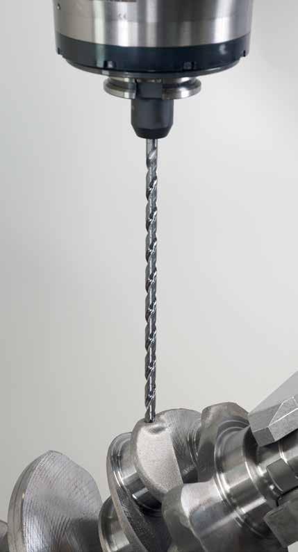
86
87 Technology Application Deep-hole drilling Pilot holes Walter Titex solid carbide deep-hole drills Walter Titex has been making solid carbide deep-hole drills since Drilling depths of 30 x Dc were reliably achieved as early as Drilling depths of up to 70 x Dc have been achieved since 2010 (see HB Product information Solid carbide drills Walter Titex XD70 Technology section on page 32). Deep-hole drilling using Walter Titex carbide tools is always without pecking, i.e. the drilling operation is not interrupted. Walter Titex deep-hole drill (140 point angle) Soft spot drilling with e.g. X treme Pilot Step 90 Pilot hole with standard tool (140 point angle) Pilot hole with Walter Titex (150 point angle) The pilot hole The pilot hole has a significant effect on: Process reliability Hole quality Service life of the deep-hole drill A pilot hole should be drilled when the final drilling depth will be 16 x Dc or more. Essentially, a pilot hole can be created with any solid carbide tool that has the same point angle as the deep-hole drill to be used subsequently. Its diameter must also be the same as that of the deep-hole drill. Walter Titex pilot drills Walter Titex deep-drilling technology encompasses not only solid carbide deep-hole drills but also special pilot drills (see HB Product information Solid carbide drills Other Walter Titex pilot drills section on page 31). Walter Titex pilot drills have the following advantages over conventional carbide drills: Higher degree of stability Point angle adjusted to the application Diameter tolerance adjusted to the application Special conical design These properties offer the following benefits: Even greater process reliability Further optimised hole quality Significantly longer service life of the deep-hole drills thanks to protection of the peripheral cutting edges and soft spot drilling of the deep-hole drills (see image above) Page information refers to: HB = this handbook GK = Walter General Catalogue 2012 EK = Walter Supplementary Catalogue 2013/
88 Technology Application Drilling strategy 1: XD Technology 30 x D C suitable for: A6685TFP A6985TFP A6785TFP A6794TFP A6885TFP A6994TFP P M K N S H O 1 Pilot drilling 2 x D c bar on 2 x D c A6181TFT A7191TFT K5191TFT K3281TFT 2 Feeding in off XD Technology 3 Spot drilling 1.5 x D c bar on n max = 100 rpm v f = 1000 mm/min XD Technology 4 Deep-hole drilling 3 x D c bar on v c = 25 50% v f = 25 50% XD Technology v c = 100% v f = 100% 5 Retracting off XD Technology n max = 100 rpm v f = 1000 mm/min V c / V f GPS 86
89 Drilling strategy 2: XD Technology 30 x D C suitable for: A6685TFP A6885TFP A6785TFP A6985TFP P M K N S H O 1 Pilot drilling bar on 8 x Dc A6489DPP 8 x D c 2 Feeding in off XD Technology 3 Deep-hole drilling 7.5 x D c bar on n max = 100 rpm v f = 1000 mm/min XD Technology 4 Retracting off v c = 100% v f = 100% XD Technology n max = 100 rpm v f = 1000 mm/min V c / V f GPS 87
90 Technology Application Drilling strategy 3: XD Technology 50 x D C suitable for: A7495TTP A7595TTP P M K N S H O Special boring tools up to 50 x D c 1 Pilot drilling bar on 2 x D c A6181TFT A7191TFT K3281TFT 2 x D c 2 Pilot drilling bar on 12 x D c A6589DPP 12 x D c 3 Feeding in off XD Technology 2 x D c With anti-clockwise rotation: n max = 100 rpm v f = 1000 mm/min 4 5 Feeding in 11.5 x D c Deep-hole drilling off bar on XD Technology Continue operation with clockwise rotation: n max = 100 rpm v f = 1000 mm/min XD Technology v c = 100% v f = 100% 6 Retracting off XD Technology n max = 100 rpm v f = 1000 mm/min V c / V f GPS 88
91 Drilling strategy 4: XD Technology x D C suitable for: P M K N S H O Special boring tools 50 x D c 1 Pilot drilling bar on 2 x Dc A6181TFT A7191TFT K3281TFT 2 x D c 2 Pilot drilling bar on 20 x D c A6785TFP 20 x D c 3 Feeding in off XD Technology 2 x D c With anti-clockwise rotation: n max = 100 rpm v f = 1000 mm/min 4 5 Piloting 19.5 x D c Deep-hole drilling off bar on XD Technology Continue operation with clockwise rotation: n max = 100 rpm v f = 1000 mm/min XD Technology v c = 100% v f = 100% 6 Retracting off XD Technology n max = 100 rpm v f = 1000 mm/min V c / V f GPS 89
92 Technology Application Drilling strategy 5: Micro XD Technology 30 x D C suitable for: A6489AMP A6789AMP A6589AMP A6889AMP A6689AMP A6989AMP P M K N S H O 1 Pilot drilling bar on 2 x D c A6181AML 2 x D c 2 Feeding in off XD Technology 3 Deep-hole drilling 1.5 x D c n max = 100 rpm v f = 1000 mm/min bar on XD Technology v c = 100% v f = 100% 5 Retracting off XD Technology n max = 100 rpm v f = 1000 mm/min V c / V f GPS 90
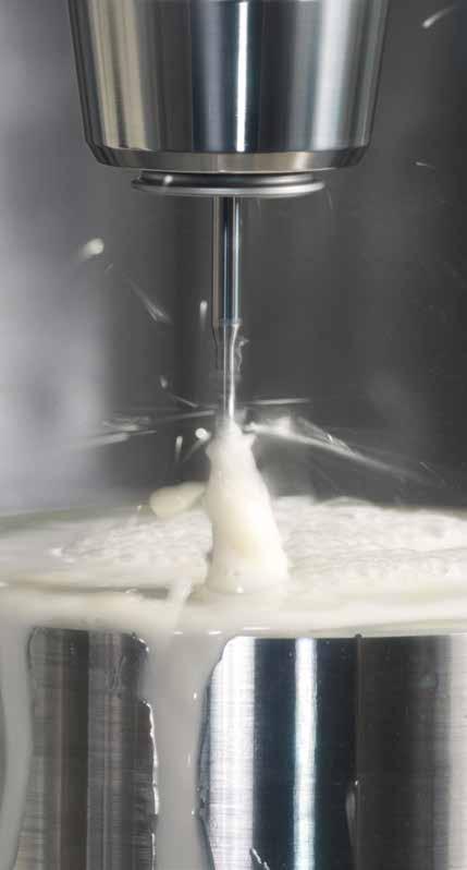
93
94 Technology Application Deep-hole drilling Solid carbide and gun drills Comparing solid carbide deep-hole drills and gun drills Drilling deep holes using gun drills is a common and reliable procedure. In many applications, these tools can be replaced with solid carbide deep-hole drills. This enables the machining speed and therefore productivity levels to be increased enormously, as in some cases higher feed rates can be achieved using helical solid carbide drills (see image) Solid carbide twist drill Walter Titex solid carbide deep-hole drill Feed rate v f (mm/min) Increase in productivity e.g. 20 x D c = 600% HSS-E drill Gun drill Relative drilling depth (l/d c) In addition to increasing productivity, using Walter Titex solid carbide deep-hole drills has the following positive effects on the production of parts/ components with deep holes: Shortened process chain Complete machining in one clamping arrangement No outsourcing required Shorter lead times High versatility Easy to use No particular requirements on cooling lubricant No particular requirements on the coolant pressure Sealing of the work room is not necessary thanks to the low level of coolant pressure required No investment in deep-drilling machines required Use on machining centres No need to purchase drill bushes, steady-rest bushes or sealing rings No problems with cross holes 92
95 Technology Application Micromachining Walter Titex solid carbide micro-drills Walter Titex offers a comprehensive range of drilling tools for use in micromachining. The smallest solid carbide high-performance tools have a diameter of 0.5 mm without an internal coolant supply and a diameter of 0.75 mm with an internal coolant supply (see Tools Solid carbide Micromachining section). The largest micro-tool has a diameter of 2.99 mm. The range includes internally cooled and externally cooled tools. Drilling depths of up to 30 x Dc can be achieved with tools from the catalogue range. Externally cooled Alpha 2 Plus Micro tools can even achieve drilling depths of up to 8 x Dc in many materials without pecking. The dimensions of the tools are adjusted to the particular conditions when drilling small-diameter holes in accordance with Walter Titex standards. A longer shank ensures that the tool is not obscured by the clamping device (visual check). This also allows any potential interference contours to be avoided. The following points should be taken into consideration when using solid carbide micro-drills: The coolant must be filtered (filter size < 20 μm, typical size 5 μm) A coolant pressure of 20 bar is sufficient, higher pressures are possible There is a risk of the coolant pumps overheating due to the small volume of fluid flowing through them Use oil or emulsion as a coolant The surfaces of the workpieces should be as flat and smooth as possible, as bumps generate higher lateral forces (risk of the tool breaking or rapid wear) The use of hydraulic-expansion adaptors or shrink-fit adaptors is recommended The drilling strategy should always be followed when drilling deep holes (see page 86 onwards) and the correct X treme Pilot 150 pilot tool used (type A6181AML). Solid carbide high-performance tools for small diameters are available in both the established Alpha range and the newer X treme drill family (see HB Product information Solid carbide drills Walter Titex X treme M, DM8..30 section from page 28 onwards). Page information refers to: HB = this handbook GK = Walter General Catalogue 2012 EK = Walter Supplementary Catalogue 2013/


96 Technology Application Wear Optimum time for regrinding Tool stopped at the last minute The peripheral cutting edge will soon break, which then poses a risk to the components Condition shortly before the end of the tool s service life Components at risk Optimum time The tool can be reconditioned several times 94


97 Chisel edge wear Action Send for reconditioning Shortening of the tool Approx. 0.3 to 0.5 mm depending on wear Wear on the peripheral cutting edge Action Send for reconditioning Shortening of the tool Approx. 0.3 to 0.5 mm depending on wear Severe wear on the main and peripheral cutting edges Action Remove the tool from the machine sooner Send for reconditioning Shortening of the tool Approx. 1.0 mm below the chamfer wear 95

98 Technology Application Wear Wear on the chamfers Action Remove the tool from the machine sooner The chamfer is deformed Send for reconditioning Shortening of the tool Depends on the damage to the chamfers Wear on the chisel edge and main cutting edge Action Send for reconditioning Shortening of the tool 0.5 mm under the peripheral cutting edge 96


99 Extreme material deposits and chipping Action Remove deposits Send for reconditioning Shortening of the tool Approx. 0.3 to 0.5 mm depending on wear Chipping at the corners of the main cutting edge Action Shortening of the tool and grinding of a new point Send for reconditioning Shortening of the tool At least 1 mm under the chipping Cracks/chipping on the chamfer Action Send for reconditioning Shortening of the tool Grinding of a new point 97


100 Technology Application Wear Chipping on the peripheral cutting edges Action Remove the tool from the machine sooner Send for reconditioning Shortening of the tool 1.0 mm below the chipping Chipping on the chamfer Action Send for reconditioning Shortening of the tool Set the tip back until the damage has been removed completely 98


101 Deposits on the main cutting edge with damage Action Send for reconditioning Shortening of the tool Regrind the point, shorten by approx. 0.3 to 0.5 mm depending on wear Deposits on the chamfer with damage Action Send for reconditioning Shortening of the tool Shorten and recondition the tool 99
 Inclined exit during through-hole drilling results in interrupted cut Reduce the feed rate for through-hole drilling (-")
102 Technology Application Problems Causes Solutions Chipped peripheral cutting edges Excessive edge wear causing the corner to chip Recondition promptly Workpiece springs up when throughhole drilling, tool therefore catches Reduce the feed rate for through-hole drilling (- 50%) Inclined exit during through-hole drilling results in interrupted cut Reduce the feed rate for through-hole drilling (- 50%) Through-hole drilling of a cross hole results in interrupted cut Reduce the feed rate for throughdrilling of the cross hole (- 50% to - 70%) Centring with too small a point angle, tool therefore drilling with the edges first Pre-centre with point angle > point angle of drill Mechanical overload of peripheral cutting edges Reduce the feed Material has hard surface Reduce the feed rate and cutting speed for drilling on entry (and, if applicable, on exit if hard on both sides) (- 50% in both cases) Material too hard Use special tool for hard/ hardened materials 100

 Material too hard Use special tool for hard/ hardened")
103 Destroyed peripheral cutting edges Excessive edge wear Recondition promptly Peripheral cutting edges overheated Reduce the cutting speed Centre region destroyed Excessive wear in the centre causing it to chip Recondition promptly Mechanical overload of point Reduce the feed Material has hard surface Reduce the feed rate and cutting speed for drilling on entry (- 50%) Material too hard Use special tool for hard/ hardened materials 101

104 Technology Application Problems Causes Solutions Drill bit breakage Excessive wear causing breakage due to overloading Recondition promptly Chip accumulation Check that the flute length is at least equal to drilling depth +1.5 x d Use a drill bit with better chip transport properties Drill bit wanders on entry (e.g. because bit is too long, entry surface is not flat, entry surface is inclined) Centre or pilot drill On lathes: Alignment error between rotary axis and drill axis Use an HSS(-E) drill bit or a drill bit with a steel shank instead of a solid carbide tool Workpiece not clamped with adequate stability Improve workpiece clamping Chipping on cylindrical lands Handling error Keep tools in their original packaging Keep tools apart/prevent contact between them 102
105 Hole too large ø Excessive centre wear or irregular wear Recondition promptly Drill bit wanders on entry (e.g. because bit is too long, entry surface is not flat, entry surface is inclined) Centre-mark Concentricity error of the chuck or the machine spindle Use a hydraulic expansion chuck or shrink-fit chuck Check and repair the machine spindle Workpiece not clamped with adequate stability Improve workpiece clamping Hole too small ø Excessive wear of cylindrical lands or edges Recondition promptly Hole not round Reduce the cutting speed 103

106 Technology Application Problems Causes Solutions Poor surface finish Excessive wear of the peripheral cutting edge or cylindrical lands Recondition promptly Chip accumulation Check that the flute length is at least equal to drilling depth +1.5 x d Use a drill bit with better chip transport properties Poor chip formation Excessive wear of the main cutting edge affecting chip formation Recondition promptly Chips are too thin as the feed rate is too low Increase the feed Inadequate cooling causing the chips to overheat Use internal cooling instead of external cooling Increase the pressure of the internal coolant supply Program interruptions in the feed motion, if necessary 104
Solid Carbide Taps.
 Solid Carbide Taps www.vergnano.com VERGNANO CARBIDE TAPS The use of carbide tools has increased significantly in the last few years. Nowadays turning, drilling and milling operations are done, for the
Countersinks. Smooth cutting, perfect chamfering - Counterbores - Cross Hole - Single Flute - Three Flute
 Countersinks Countersinks Smooth cutting, perfect chamfering - Counterbores - Cross Hole - Single Flute - Three Flute smooth cutting perfect chamfering countersinks Product Code: C108 This new generation
D101 - JOBBER DRILLS - Silver Bullet
 D101 - JOBBER DRILLS - Silver Bullet Sutton Tools Silver Bullet jobber drills are a general purpose drill bit designed for machine and hand held drilling in a wide range of ferrous & non-ferrous materials
TOOLING NEWS E-116. New SumiDrill Power Series Expansion. SDP Type. All-rounder for Drilling
 TOOLING NEWS E-116 P M K N S H New SumiDrill Power Series Expansion All-rounder for Drilling - High efficient drilling in wide application range - General purpose application - Maximum performance by increased
TOOLMAKER SOLUTIONS Custom-Made Inserts Blanks
 Non-ISO carbide insert blanks for threading, parting, grooving, drilling, reaming and milling applications TOOLMAKER SOLUTIONS Custom-Made Inserts Blanks HYPERION CUSTOM-MADE INSERT BLANKS Hyperion manufacturers
HR 500. USA Edition HR 500 Solid carbide high-performance reamers up to Ø 20 mm for universal application
 Solid carbide high-performance reamers up to Ø 20 mm for universal application T Solid carbide reamer head for Ø 16-38 mm NEW Cast Solid carbide high-performance reamers for the machining of and achieving
Index. MEGA-Spike-Drill. Product presentation 4 General information 5 Technical specification 5. MEGA-Spike-Drill M9535 6
 The tool specialists for the trade. Standard product line MEGA-Spike-Drill The tool specialists for the trade. MILLER GmbH, Präzisionswerkzeuge in Altenstadt is a member of the tool-traders-partner association
SuperV-T. Solid Carbide Spiral-Flute Deep Hole Drills for drilling depths up to 30xD. NEW: Extended standard range. Chip by Chip to the Top
 Stock SuperV-T Solid Carbide Spiral-Flute Deep Hole Drills for drilling depths up to 30xD NEW: Extended standard range Chip by Chip to the Top SuperV-T - ex-stock range Available ex-stock now: The spiral-flute
MaxiMill HFC 'Feed matters', rapid milling
 MaxiMill HFC 'Feed matters', rapid milling CERATIZIT - secrets of success Secrets of success CERATIZIT is your partner for exceptional hard material solutions. Hard materials and tools from CERATIZIT -
MaxiMill HFC 'Feed matters', rapid milling
 MaxiMill HFC 'Feed matters', rapid milling EN CERATIZIT - secrets of success Secrets of success CERATIZIT is your partner for exceptional hard material solutions. Hard materials and tools from CERATIZIT
Contents. Turning. Boring. Milling. Adaptors and clamping units. General
 Contents Turning Contents 15 Information 16 Indexable inserts and cutting tool materials 20 Toolholders for turning, grooving and threading 69 Technical information 206 Boring Contents 237 Information
MaxiMill HFC 'Feed matters', rapid milling
 MaxiMill HFC 'Feed matters', rapid milling CERATIZIT - secrets of success Secrets of success CERATIZIT is your partner for exceptional hard material solutions. Hard materials and tools from CERATIZIT -
Carbide-tipped or Cermet-tipped Special Designs Ø>20mm up to 76.2mm HR 500 HIGH-PERFORMANCE REAMERS GUHRING - YOUR WORLD-WIDE PARTNER
 Carbide-tipped or Cermet-tipped Special Designs Ø>20 up to 76.2 HIGH-PERFORMANCE REAMERS GUHRING - YOUR WORLD-WIDE PARTNER Pictograms Tool material Carbide Carbide-tipped Cermet tipped Internal coolant
TOOLMAKER SOLUTIONS Rotary Tool Blanks
 TOOLMAKER SOLUTIONS Rotary Tool Blanks Cemented carbide blanks for drills and end mills TABLE OF CONTENTS HYPERION ROTARY TOOL BLANKS SOLID BLANKS 04 06 END MILL BLANKS WITH CHAMFER, GROUND TO HYPERION
SERIES
 eep Hole rills Spiral flute drilling from 15x to 40x CNC style solid carbide gun drills Miniature CNC style gun drills Classic gun drills with brazed head RT 100 T High penetration rate EB 100 CNC style
Made in Germany. SELECTION Milling 2017 valid until Economical Tools for Milling
 Made in Germany SELECTIO Milling 2017 valid unti8.02.2018 Economical Tools for Milling EMUGE-FRAKE Industry Solutions Economical high performance cutting tools for the demanding industries of today and
Deep Hole Drills. RT 100 T coolant fed, solid carbide twist drills EB 100 solid carbide gun drills EB 80 Conventional brazed head gun drills
 eep Hole rills RT 100 T coolant fed, solid carbide twist drills EB 100 solid carbide gun drills EB 80 Conventional brazed head gun drills RT 100 T High penetration rate carbide twist drill EB 100 Solid
Tapping products B59
 Tapping Products B59 B60 Notes Hand Taps Taper, Plug and Bottoming Style - for Multi Purpose A3/A5/A7 Ansi EDP No. Bright Finish Bright Finish Bright Finish Thread per Inch No. of Taper Plug Bottoming
_ WALTER XTRA TEC INSERT DRILL Tool innovations in drilling
 Walter AG Derendinger Strasse 53. 72072 Tübingen Postfach 2049, D-72010 Tübingen Germany www.walter-tools.com Product handbook Drilling WALTER GB LTD. Bromsgrove, England 44 (0) 1527 839450 E-mail: service.uk@walter-tools.com
Core drills PRECISION TOOLS
 ORE DRILLS ore drills ore drills ore drill made of heavy-duty high speed steel. Suitable for steel (such as T-brackets, large sheets), cast iron, non-ferrous and light metals. ore drills E- ore drills
Excellent stability und. ARNO SHORT-Cut -SIS. w w w. a r n o. d e. Introducing SHORT-Cut -SIS for internal groove turning. The new SHORT-Cut holder
 Introducing SHORT-Cut -SIS for internal groove turning New w w w. a r n o. d e The new SHORT-Cut holder with optimum insert clamping. Easy handling and efficient in production. ARNO SHORT-Cut -SIS Excellent
The ingenious solution for plunge milling
 New June 2017 New products for cutting tool engineers The ingenious solution for plunge milling The new MonsterMill PCR-UNI Drilling Ramping TOTAL TOOLING=QUALITY x SERVICE 2 WNT (UK) Ltd. Sheffield Business
Introduction. Inserts. Tools. Technical information. Contents D18 D20 D30
 Contents D1 Introduction D2 Grade overview Grade description Chip grooves System characteristics for Classic Application for Classic D2 D3 D8 D10 D13 System characteristics for 900 Application for 900
Threading Tools. Cutting, milling and forming custom-made. Chip by Chip to the Top
 Threading Tools Cutting, milling and forming custom-made Chip by Chip to the Top Our Threading Tool Range Threading tools are together with drills, reamers and milling cutters the most important types
YE-SY16. Coated HSS-PM (Powder Metallurgy) Taps for High-Speed Tapping on Rigid CNC Machine
 Taps for High-Speed Tapping on Rigid CNC Machine") YE-SY16 Coated HSS-PM (Powder Metallurgy) Taps for High-Speed Tapping on Rigid CNC Machine FEATURES OF GEOMETRY Shorter thread length will reduce chip trouble at higher speed tapping conditions Tolerance
YE-SY16 Coated HSS-PM (Powder Metallurgy) Taps for High-Speed Tapping on Rigid CNC Machine FEATURES OF GEOMETRY Shorter thread length will reduce chip trouble at higher speed tapping conditions Tolerance
CARBIDE TIPPED GUN DRILLS
 CARBIDE TIPPED GUN DRILLS P M K N S H Type Shank form Drilling depth Tool material Surface Standard /mm Catalog no. Progr. page Gun drills, type AL AL HA 25xD Solid carbide AlTiN nano 2.380-12.000 55027
CoroDrill 428 Wide range of application possibilities
 A CoroDrill 428 Wide range of application possibilities Gun drills DEE HOLE MACHINING Highly productive gun drills B Easy to use Solid carbide gun drills 428.5 - Diameter range: 0.8-12.00 mm (.031 -.472
New Large Diameter Drilling Solution with a Quick Change Tip and Indexable Inserts
 Diameters (All with Inch Shanks) Inch: 1.032" - 1.781" (every 1/32") Metric: 26.0mm - 45.0mm (every 1mm) Bodies Inch Weldon Shanks Metric Shanks Available Upon Request Length/Diameter Ratio 5xD Tip Geometry
ALLROUNDER CUTTING TAPS
 ALLROUNDER CUTTIN TAPS TECHNIK FÜR EWINDE ALLROUNDER Our multi-purpose cutting taps cover a comprehensive range of materials. They can be applied for the reliable machining of various materials ranging
Ferritic/martensitic cast steel. Stainless steel Austenitic
 Machining Data for Threading ISO Material Condition Tensile Strength [N/mm ] Hardness HB Material < 0. %C Annealed 0 1 1 No. Non-alloy steel and cast steel, free cutting steel >= 0. %C Annealed 0 190
CATALOGUE MILLS & DRILLS 2017 CARBIDE END MILLS 2 TEETH OR201, OR202 3 CARBIDE END MILLS 3 TEETH OR301 4 CARBIDE END MILLS 4 TEETH OR401, OR402 5
 Mills Drills CATALOGUE MILLS & DRILLS 2017 CONTENTS CARBIDE END MILLS 2 TEETH OR201, OR202 3 CARBIDE END MILLS 3 TEETH OR301 4 CARBIDE END MILLS 4 TEETH OR401, OR402 5 CARBIDE END MILLS 4 TEETH WITH DOUBLE
Description Series Page. Turning. Grades for holemaking 256 IN1030, IN2505, IN6505. Replaceable tip drill shanks 258
 Turning Description Series Page IN1030, IN2505, IN6505 Grades for holemaking 256 Replaceable tip drill shanks 258 Drill/chamfer combo solution for inch & metric tap sizes 274 Indexable drill 276 CHAMFERING
Tooling for Composites and Aerospace Materials. Diamond coated, carbide and PCD tools Routers, drills, and end mills Full special design capabilities
 Tooling for Composites and Aerospace Materials Diamond coated, carbide and PCD tools Routers, drills, and end mills Full special design capabilities DIAMOND COATED DRILLS Material-specific design and sub-micron
Tapping Just Got Faster...
 Tapping Just Got Faster... The Synchro Tap Series is specifically designed for modern machines, where the spindle revolution (A-Axis) & feed movement (Z-Axis) are synchronously controlled. Sutton Tools
Cutting Speed Vc [M/min] Hardness
![Cutting Speed Vc [M/min] Hardness](/thumbs/94/119491657.jpg "Cutting Speed Vc [M/min] Hardness") HPD METRIC Non-alloyed steels, 1213, 13L13, 12, Cast steels Free-machining steels 12L14,1118 etc Low-alloyed steels, Cast steels(
HPD METRIC Non-alloyed steels, 1213, 13L13, 12, Cast steels Free-machining steels 12L14,1118 etc Low-alloyed steels, Cast steels(
Keeping the Customer First. Tungaloy Catalogue TE0707-E2. Cutting Tools.
 Keeping the Customer First Tungaloy Catalogue TE0707-E2 2007 Cutting Tools www.tungaloy-eu.com Selection Guides List of... 410 Selection Guides... 412 Specifications Solid Carbide s For High Speed Deep
Contents E2. R a. Introduction. ProfileMaster. EcoCut. Index. Productivity. System overview E42 E3-E4. Designation system E43.
 Contents E2 Introduction ProfileMaster Productivity E3-E4 System overview E42 Designation system E43 EcoCut System overview E6 Chip grooves, grades E44-E46 Designation system E7 Machining methods E47-E48
AlTiN nano. Al- TiCN. Morse taper DIN 8041 WN. to Stock standard. SuperV- T. SuperV- 95-GG. SuperV- 95-GN. SuperV- IK-F. SuperV- AP mini AL
 CARBIDE DRILLS ISO-CODES P M K N S H Steel, high-alloyed steel Stainless steel Grey cast iron, spheroidal and malleable cast iron Aluminium and other non-ferrous metals Special-, super- and Ti-alloys Hardened
DRILLING TOOLS CARBIDE & HSS-PM SPADE DRILLS TECHNICAL DATA
 DRILLING TOOLS i-dream, CARBIDE INSERTS SOLID CARBIDE DREAM - GENERAL (with & without Coolant Holes) SOLID CARBIDE DREAM - HIGH FEED SOLID CARBIDE DREAM - INOX (with Coolant Holes) SOLID CARBIDE DREAM
Endmills. Drills. Reamers. Where high performance is the standard. Countersinks Edgehog. Burrs. Performance, Precision, Economy
 Edgehog Where high performance is the standard Performance, Precision, Economy M.A. FORD Quality Policy Ultimately we are judged by our customer. The product that we supply must satisfy our customers needs
Countersink Section 2018 Master Catalog
 Countersink Section 2018 Master Catalog For more than 95 years, M.A. Ford has been at the cutting edge of tooling design and manufacturing and has developed an enviable global reputation for performance
Carbide Burs - Double Cut - Aluminium Cut - Comprehensive range of shapes to suit your application - Standard & extra length available - Sets &
 CARBIDE BURS Carbide Burs - - Aluminium Cut - Comprehensive range of shapes to suit your application - Standard & extra length available - Sets & merchandisers Carbide Bur Finder Cylindrical, Square End
K_MILL. The new powerful face milling cutter
 The new powerful face milling cutter PREZISS TOOLS in its constant evolution to improve tooling production continuously invests in new technologies & technical knowledge. Because of our concern, we work
SUMMARY TECHNICAL INSTRUCTIONS. Technical Information. Geometries and feed rates. Cutting data. Carbide grades for grooving and parting off
 SUMMARY TECHNICAL INSTRUCTIONS Technical Information Grooving / Side turning Face grooving Profiling Threading Parting off Page 2-5 6 7 8-9 10-11 Geometries and feed rates Cutting data Inserts type 217
M.A. Ford Where high performance is the standard. Phone: or
 For more than 95 years, M.A. Ford has been at the cutting edge of tooling design and manufacturing and has developed an enviable global reputation for performance and precision in advanced solid carbide
Core drills PRECISION TOOLS
 CORE DRILLS Core drills Core drills Core drill made of heavyduty high speed steel. Suitable for steel (such as Tbrackets, large sheets), cast iron, nonferrous and light metals. Core drills E Core drills
CARBIDE. Being the best through innovation NC-SPOTTING DRILLS. - CENTERING and CHAMFERING
 Being the best through innovation - CENTERING and CHAMFERING SELECTION GUIDE ITEM MODEL DESCRIPTION SIZE MIN MAX PAGE D5306 D5307, D D 1 D5315 D5318, D3.0 D 111 RECOMMENDED CUTTING CONDITIONS 112 8 phone:+82-32-526-09,
2007 CATALOG. HIGH PERFORMANCE HSS-E PM Carbide Cut & Form Taps Thread Types UNC UNF M MF Standard Sizes 2-56 to 1 1 /2-6 M1.4 x 0.30 to M36 x 1.
 HIGH PERFORMANCE PM Cut & Form Taps Thread Types UNC UNF M MF Standard Sizes 2-56 to 1 1 /2-6 M1.4 x 0.30 to M36 x 1.50 GUHRING Tap Compass Tap Selection Made Easy 2007 CATALOG HOW TO FIND THE MOST SUITABLE
HIGH SPEED STEEL TWIST DRILLS
 HIGH SPEED STEEL TWIST DRILLS ISO-CODES P M K N S H Steel, high-alloyed steel Stainless steel Grey cast iron, spheroidal and malleable cast iron Aluminium and other non-ferrous metals Special-, super-
SuperV-AP Drilling system. A system that offers high performance. Cip by Chip to the Top
 Drilling system A system that offers high performance Cip by Chip to the Top - Drilling system Overview Type DIN Tool material Surface finish Drilling depths Shank Internal cooling Point grinding Point
MaxiMill the 90 shoulder and slot milling system
 MaxiMill 211 - the 90 shoulder and slot milling system CERATIZIT - the parent companies Headquarters and parent company in MAMER / Luxembourg Parent company in REUTTE / Austria Hard material matters -
CATALOG. Featuring BEST VALUE IN THE WORLD OF CUTTING TOOLS
 2010 2011 CATALOG Featuring NEW PRUCTS! BEST VALUE IN THE WORLD OF CUTTING TOOLS CONTENTS Inserted Drills 3 9 i - Dream drills 3 5 i - Dream Drill Carbide Inserts and Holders 6 9 i - Dream Drill Data and
CUSTOM ADD-ONS FOR ENGLISH UNITS
 CUSTOM ADD-ONS FOR ENGLISH UNITS Specials Feed Control Valves See note below for location in the Specification Code V1 Dual Feed Manifold V2 Skip Feed Cam Bar (Not Shown) Please specify rapid distance,
K_MILL. The new powerful face milling cutter
 The new powerful face milling cutter PREZISS TOOLS in its constant evolution to improve tooling production continuously invests in new technologies & technical knowledge. Because of our concern, we work
Australian High Performance Catalogue. effective 1st August 2011
 Australian High Performance Catalogue effective 1st August 2011 Application Guide Colour Band Selection Sutton Tools has made the tool selection for cutting different materials easy by applying colour
KomPass REAMING. Inch and Metric
 KomPass REAMING Inch and Metric KomPass REAMING BENEFITS for you As a brand of the KOMET GROUP, DIHART is known for its precision reaming technology which is sure to take you to the next level. For the
Price/1. Price/1. Price/1. 1/ 8 3/ 8 1 1/ 2 1/ 8 10g -4580K / 4 3/ 4 2 1/ 2 1/ 4 30g -4660K / / 2 3/ 8 60g -4740K 291.
 2 Flute For optimum performance and maximum swarf removal when plunging, slotting and routing in most materials including brass, aluminium, non-ferrous and other soft materials. Manufactured to USCTi Standards.
UPDATED. High Productivity, Quick Change, Tipped Drills for Large Diameter Hole Making. Features & Benefits:
 High Productivity, Quick Change, ipped Drills for Large Diameter Hole Making Ingersoll has introduced a new drilling line for large diameter hole applications. he Spadewist, with an optimized cutting edge
THREAD MILLING. SC-LINE Thread milling cutters WITH HIGH-END PERFORMANCE RAPID GÜHRING YOUR WORLDWIDE PARTNER
 RAPID THREAD MILLING WITH HIGH-END PERFORMANCE top performance thread milling up to 1300 N/mm² up to 50 % reduced cycle time increase in tool life by up to 100 % reliable machining and even higher process
Contents DRILLING TOOLS
 DRILLING TOOLS i-dream DRILLS, CARBIDE INSERTS SOLID CARBIDE DREAM DRILLS - GENERAL (with & without Coolant Holes) SOLID CARBIDE DREAM DRILLS - HIGH FEED (with Coolant Holes) SOLID CARBIDE DREAM DRILLS
CARBIDE DRILLS 15-40xD
 CARBIDE DRILLS 15-40xD ISO-CODES P M K N S H Steel, high-alloyed steel Stainless steel Grey cast iron, spheroidal and malleable cast iron Aluminium and other non-ferrous metals Special-, super- and i-alloys
HIGH PERFORMANCE PRODUCT
 HIGH PERFORMANCE PRODUCT SYNCHRO TAPS (HSS-PM) High Speed, High Precision for CNC Machining Synchro Tap has an optimized short thread length and high thread reliefs. We guarantee you shorter cycle time,
Sandvik Hyperion Metal Cutting. Gear Cutting Applications
 Sandvik Hyperion Metal Cutting Gear Cutting Applications Hob Blanks Standard Hob blanks available with 12 teeth or 15 teeth configuration. Sandvik Hyperion Benefits: Reduction in EDM wire cutting - reduces
Germany usa canada France Great Britain mexico KomPass italy Threading austria china poland Japan russia korea switzerland spain india
 KomPass Threading KomPass Threading Benefits for you As a strong brand of the KOMET GROUP, JEL and its innovations of stand for modern thread production. From conventional thread production to the technologically
Cost reduction through Performance. SHARK-CUT + SHARK-CUT Rebore. Introducing Shark-Cut Rebore Tools and Inserts for boring
 Introducing SharkCut Rebore Tools and Inserts for boring www.arno.de Due to the unique positioning and insert geometry excellent hole quality is achieved also for deeper holes. Easy handling and efficient
MULTIPLEX HPC THE INTERCHANGEABLE INSERT DRILLING SYSTEM FOR HOLES UP TO 10 X D UP TO DIAMETER 40.0 MM
 EN Precision Cutting Tools MULTIPLEX HPC THE INTERCHANGEABLE INSERT DRILLING SYSTEM FOR HOLES UP TO 10 X D UP TO DIAMETER 40.0 MM + Edition 2016 MULTIPLEX HPC TECHNOLOGY AND ADVANTAGES With the new interchangeable
1. 3 : Walter-Titex-Prototyp 3, !!
 ( ), 1. 3 : Walter-Titex-Prototyp 3,. 280. 2000....!! 2. WALTER Wuxi Co. Ltd. ( ) 1998 1, 200.,. 3 DMG,.. 3. S 2 S 3 Heilongjiang Jilin : 200 Xinjiang Tibet 60 20 8 S 5 S 6 Gan su Quinghai Yunnan Sichuan
A New Positive Multi Corners Milling Line
 1/9 A New Positive ulti Corners illing Line 2/9 With the increasing popularity of small machining centers, TaeguTec is pleased to launch a new single-sided line of positive seven corners insert that generates
SG DRILL SERIES POWDERED METAL COBALT DRILLS
 SG DRILL SERIES POWDERED METAL COBALT DRILLS Contributing to Progress in the World of Product Manufacture The NACHI Difference ~ NACHI-FUJIKOSHI CORP. is a pioneer of precision cutting tools in Japan and
Range of products. Ern st Reime The tradition continues!
 PI 0902 Range of products Ern st Reime The tradition continues! escription of the symbols Cutting geometry Thread form S 30 S = Helix angle 2x Through hole Blind hole Thread depth 2x Shank design Plain
Your Cutting Tool Solution for DRILLS
 Your Cutting Tool Solution for DRILLS DRILLS / VISUAL INDEX AQUA DRILL EX STUB LENGTH AQ EX List 9600 List 9601 h8 15 0 h6 Metric s Fractional s Specs/s Speeds/s P22, 2 P2 AQUA DRILL EX JOBBER LENGTH AQ
DHC. Differential Helix Cutter
 DHC Differential Helix Cutter Universal Short and Long End Mills for the Highest Productivity in Roughing and Finishing Applications (Standard & with Corner Radius) 2 x d 1 x d DHC (Differential Helix
SpyroTec GÜHRING YOUR WORLDWIDE PARTNER. 90 countersinks with convex cutting edges. Twisted HSS and HSCO countersink
 90 countersinks with convex cutting edges universal application in nearly any material round, precise and chatter-free countersinking reduction of feed force by 60% reduction of radial force by 50% SpyroTec
The Ultimate Drill Family For High Heat Applications
 rt 100 0 us The Ultimate Drill Family For High Heat Applications The ultimate drill for high heat applications Increased feed rates -- 3 to 5 times higher than conventional style drills due to these features:
RT 100 Al. Strong in aluminium GÜHRING YOUR WORLDWIDE PARTNER
 Strong in aluminium cost-effective drilling of aluminium-, copper-, brass- and bronze-alloys as well as plastics entire material range from soft and tough non ferrous alloys to brittle aluminium alloys
NPA. ISCAR Introduces the Narrowest mm Indexable Slitting Cutter. New Product Announcement. Page 1 / 5
 NPA ISCAR Introduces the Narrowest - 0.8 mm Indexable Slitting Cutter Page 1 / 5 Page 2 / 5 Highlights ISCAR is introducing the narrowest indexable slitting tool in the market: indexable SGST disk slitting
Small but Powerful Positive Insert with Dovetail Design
 1/9 Small but Powerful Positive Insert with ovetail esign 2/9 Small but Powerful Positive Insert with ovetail esign TaeguTec is proud to introduce a brand new product line to its popular CHASEMI family.
Cutting Data Reference Values
 Cutting Data Reference Values SolidCUT Material Strength TINAMATIC Ø 4 Vc (m/min.) fz mm A R F N S H 1.1 General construction steel < 800 N/mm² 80-250 0,03-0,06 1.2 Free cutting steel < 800 N/mm² 80-250
MAXIMILL MILLING SYSTEM ENGINEERED SIMPLICITY. 8 Cutting Edges. More milling. More parts. More profits.
 MAXIMILL 491 MILLING SYSTEM ENGINEERED SIMPLICITY 8 Cutting Edges. More milling. More parts. More profits. www.ceratizit.com 22 We work hard to make things easy. It takes a lot of engineering and know-how
B5 & B9 Reaming Heads
 B5 & B9 Reaming Heads February 2011 1/14 February 2011 2/14 B5 & B9 reaming heads Following the very successful reaming performance obtained with B6, B7, and B8 reaming heads, TaeguTec has now expanded
MAXIDRILL 900 TAKE DRILLING TO A WHOLE NEW LEVEL.
 MAXIDRILL 900 TAKE DRILLING TO A WHOLE NEW LEVEL. www.ceratizit.com 22 2 MaxiDrill 900. Meet the next MaxiDrill 900 intro headline generation in drilling performance. will go here. MaxiDrill 900 delivers
Jongen Werkzeugtechnik. Working depth. Drilling by JONGEN. 3 x D. BP 04 to 12
 Jongen Werkzeugtechnik Working depth 3 x D Drilling by JONGEN BP 04 to 12 THE TOOL New at Jongen: universally applicable high-performance drill for use on lathes and milling centers. It offers the highest
Mounted Points Mounted Points
 Mounted Points I 1 iamond and CBN ools 205 Mounted Points able of Contents ool drive Contents Page General information 3 he fast way to the best tool 4-5 Ordering instructions 6 Mounted points Hardness
Complete range. Threading tools. Chip by Chip to the Top
 Complete range Threading tools Chip by Chip to the Top Threading tools for every application wide range of thread forms thread cutting, forming and milling for all hole types with or without internal cooling
High Productivity, Quick Change, Tipped Drills for Large Diameter Hole Making
 Diameters: Metric: 26.0mm - 32.9mm (.1mm increments) 33.0mm - 41.0mm (.5mm increments) Inch: 1.031-1.625 (every 1/32 ) High Productivity, Quick Change, Tipped Drills for Large Diameter Hole Making pade
For Gear, Spline & Rack Manufacturing
 For Gear, Spline & Rack Manufacturing INC Advanced Technologies for Gear, Spline and Rack Manufacturing See it in action The VARDEX Gear Milling Concept Advanced milling tools with multi-flute indexable
THREADING TOOLS FOR AEROSPACE MATERIALS
 aero THRDING TLS FR RSPC MTRILS N-ID-0116 RSPC PPLICTIN RNG ircraft materials Tool manufacturers are often confronted with tricky challenges when working for the viation industry: The machining of hard
Rotary burrs Fields of application: for high-alloy
 » ROTARY BURRS Rotary burrs The high-performance tungsten carbide rotary burrs provide maximum cutting edge stability with a simultaneous high tenacity of the cutting edge. High-performance tungsten carbide
Alloy Steel Application Material Group
 Alloy Steel Application Material Group 1.4 1.5 1.6 General Information Examples of Workpiece Materials - Categorisation into Application Material Groups (AMG) Application Material Group (AMG) Hardness
for the machining of steel materials high cutting values and tool life minimum machining times and consistently good hole quality RT 100 S
 for the machining of steel materials high cutting values and tool life minimum machining times and consistently good hole quality T 100 S STEEL MACHIN INING P Strong in steel T100 T 100 S was especially
RD-SAF Face milling and profiling cutter with positive round inserts
 RD-SAF Cutter program, RD 2, RD 6, RD 20 ødm (CM) m l 2 ødm m B ød c ød c Morse taper Arbor mounting D c D 3 Max. dm m l 2 l 3 B F Z Nb of inserts Coolant channels Morse taper RD-2/032-03-CM3-080 20.00
HSS-E PM. Al- TiZrN TiAlN TiN Al- TiCN ~DIN 376 ~DIN 371 ~DIN 371/376 DIN 357 DIN 5157 DIN EN WN. Produktiv HX. Intensiv N-X.
 THREAG TOOLS ISO-CODES M K N S H Steel, high-alloyed steel Stainless steel Grey cast iron, spheroidal and malleable cast iron Aluminium and other non-ferrous metals Special-, super- and Ti-alloys Hardened
CrazyDrill SST-Inox. World s Newest Tool. Solid carbide drill for stainless steel and super alloys
 CrazyDrill SST-Inox World s Newest Tool Solid carbide drill for stainless steel and super alloys 2 CrazyDrill SST-Inox The latest stroke of genius from Mikron Tool 2 drills for stainless steel and super
TUBE AND SHEET DRILLS
 TUBE AND SHEET DRILLS 03 Tube and sheet drills The flutes of the RUKO high performance tube and sheet drills are BN ground from the solid hardened form. Because BN (cubical boron nitride) is a much harder
CARBIDE INSERT. Being the best through innovation. Available for General Steels and for Stainless Steels
 INSERT Being the best through innovation Available for General and for Stainless SELECTION GUIDE ITEM MODEL DESCRIPTION PAGE YA1A / YB1A YA2C / YB2C i / idream Drill General / idream Drill INOX 34 YB1A
For Gear, Spline & Rack Manufacturing
 For Gear, Spline & Rack Manufacturing METR Advanced Technologies for Gear, Spline and Rack Manufacturing See it in action The VARDEX Gear Milling Concept Advanced milling tools with multi-flute indexable
MaxiMill HPC12 / HSV22 Milling with PCD and CBN
 MaxiMill HPC12 / HSV22 Milling with PCD and CBN CERATIZIT - secrets of success Secrets of success CERATIZIT is your partner for exceptional hard material solutions. Hard materials and tools from CERATIZIT
Mounted Points Mounted Points
 Mounted Points I 1 iamond and CBN ools 205 Mounted Points able of Contents ool drive Contents Page General information 3 he fast way to the best tool 4-5 Ordering instructions 6 Mounted points Hardness
Perfect HSS / HScO tools
 Made by Perfect HSS / HScO tools ++High quality ++Attractive prices HigH-quality tools at attractive prices Discover our high-quality tool range for the following applications: Drilling milling tapping
HSS rolled. HSS ground. HSS Co 5 ground. HSS-TiN ground. Twist drills DIN 338 type N. Point cuts:
 Twist drills DIN 338 type N High performance twist drill suitable for all normal drilling in conventional materials. Point cut: helical point Helix angle: 20-30 tolerance: h8 Right-hand cutting 1,0 up