University of Pretoria Z Tang (2006) Chapter 8 Studies of acicular ferrite by thin foil TEM
|
|
|
- Kelley Robinson
- 6 years ago
- Views:
Transcription

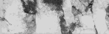
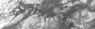
![Diaz-Fuentes [78] has also found similarly two types of acicular ferrite by isothermal treatment in a medium carbon steel.](/docs-images/74/70513666/images/1-1.jpg "Figure 8.13 shows some parallel laths in a lath colony in which some parallel laths interweave with one another.")

, these parallel laths are possibly not from a bainite structure.")
, and no cementite within the laths or on interlath positions by TEM.")
![Acicular ferrite nucleates intragranularly on inclusions [71,74,136,137] in weld pools and not intergranularly, while its](/docs-images/74/70513666/images/1-5.jpg "nucleation may possibly also be enhanced by dislocations resulting from prior deformation, as was described in section 7.5.")
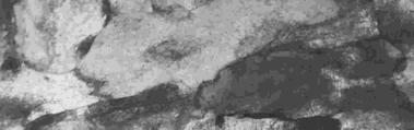
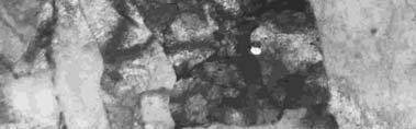
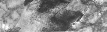
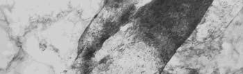
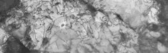
1 8.2 Two types of acicular ferrite Structure with parallel laths There appeared to be two types of acicular ferrite laths that were observed in those alloys cooled with a rapid cooling rate of 47 ºCs -1 after the hot rolling. Diaz-Fuentes [78] has also found similarly two types of acicular ferrite by isothermal treatment in a medium carbon steel. Figure 8.13 shows some parallel laths in a lath colony in which some parallel laths interweave with one another. This can be clearly seen in figures 8.13 and The apparent preferred habit plane of the laths in colony 1 appears to be different from that of the nearby colony 2 in figure Combining this conclusion with the optical micrographs of this alloy (in figure 7.29), these parallel laths are possibly not from a bainite structure. This conclusion is based on no grain boundaries that can be observed in optical metallography (figure 7.29), and no cementite within the laths or on interlath positions by TEM. Acicular ferrite nucleates intragranularly on inclusions [71,74,136,137] in weld pools and not intergranularly, while its nucleation may possibly also be enhanced by dislocations resulting from prior deformation, as was described in section 7.5. The different parallel laths are possibly primary laths which have the same growth direction [75] and with a secondary lath that may nucleate at the tip of the primary one but with both having the same habit plane and orientation, resulting in a parallel sheaf morphology. Colony 1 Colony of laths (a) Colony 2 3µm (b) 1µm
2 Figure 8.13 Parallel lath morphology in a colony in alloy #3 after rapid cooling at a rate of 47 ºCs -1 after the hot rolling process. Madariaga and Bhadeshia [75] reported a similar parallel lath morphology of acicular ferrite in a medium carbon micro-alloyed steel that was isothermally treated at a relatively low temperature of 400 ºC. The two reasons given by the authors for the formation of a parallel lath microstructure are: (1) The lower stability of the austenite with low carbon enrichment close to the ferrite tip rather than on the face of the lath, leading to the secondary plate of ferrite nucleating at the tip of previous one. (2) Madariaga [75] reported that some retained austenite and cementite was found between the ferrite platelets. In that case, there was enough time for diffusion of carbon after the acicular ferrite formation because of the isothermal treatment. The excess carbon in acicular ferrite may be rejected into the austenite after the acicular ferrite formation and the cementite can be formed from the carbonenriched austenite during this continued isothermal treatment. The austenite close to the face of the platelet has more carbon than the tip and as a result, cementite is distributed differently in the different sections of the boundary between adjacent platelets. On the contrary, however, the parallel laths found in this study appear to be different from those in Madariaga s study [75]. No cementite was observed here on boundaries between laths or within the laths in any of the alloys in this study. Furthermore, the phase transformation in this study must have taken place in a few seconds due to the rapid cooling rate of 47 ºCs -1, far less than in any isothermal treatment as was used by Madariaga. Consequently, the nucleation and growth of laths in the alloys studied here are probably different from those in Madariaga s study. The nucleation of a secondary lath is dependent not only on the carbon depletion into the parent austenite in front of the interface with the primary lath (the excess carbon from the primary lath will be rejected into the adjacent austenite [75,78], which then is not suited for the formation of a secondary lath), but also on the defects in the austenite adjacent to the primary lath, which resulted from the hot rolling process below the T nr. These defects, therefore,


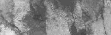
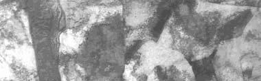
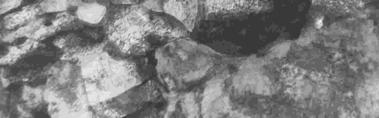
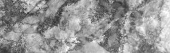
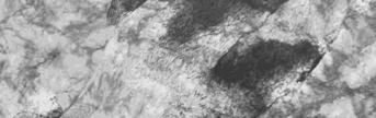
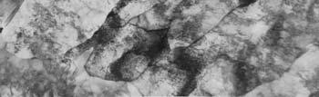
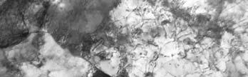
3 assist in the nucleation of the ferrite nuclei [134]. On the other hand, the secondary lath was possibly formed heterogeneously along the primary one in order to decrease the activation energy of transformation. A set of parallel laths that composes a colony, is typical of acicular ferrite found in this study. The boundary between the colonies could not be observed under the optical microscope (figure 7.29) because the size of the colonies was too small and the orientation differences between colonies were chaotic. The morphology at the end of the laths in figure 8.14 may not support the assumption that they had nucleated on the boundary of the austenite. Colony 1 Colony 2 2µm Figure 8.14 Interwoven arrangement between lath colonies in alloy #4 after a fast cooling rate of 47 ºCs -1 after the hot rolling process
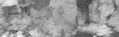
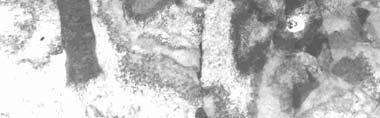
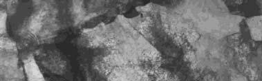
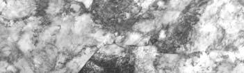
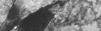
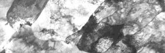
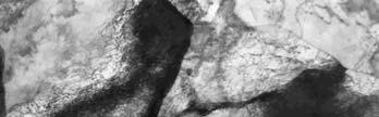
4 8.2.2 Structure with interwoven laths Another type of lath structure may be seen in figures 8.15 and Laths are chaotically arranged and interwoven in between each other (marked with A, B, C, D, E and F). Each lath had its own apparent growth direction. This lath morphology appears to be the same [69,90,134] as that which other researchers have observed in welds in which many non-metallic inclusions in the weld pool act as high density nucleation sites for acicular ferrite [57,81,138]. Such a nucleation process will result in various orientations, interwoven in the nature of acicular ferrite formation. Although there were relatively few non-metallic inclusions in the alloys in the present study, some interwoven laths were still observed even though this was not typical acicular ferrite morphology in these alloys. Where this did occur, the primary acicular ferrite (AF) lath may have nucleated on an inclusion with the next lath then nucleated on the face of the previous lath, i.e. on the interface of the primary AF lath and the untransformed austenite. The direction of growth will favour the direction in which the retarding forces of the transformation are the lowest. Figure 8.15 shows that laths B, C and F apparently nucleated on the face of lath A, while lath G probably nucleated on lath F. It, therefore, may be concluded that there are two types of laths of acicular ferrite present in the alloys studied in this work, namely, parallel and interwoven laths with the former being the dominant type


5 D B G F A C (c) 1µm E Figure 8.15 Interwoven laths micrographs in alloy #3 after fast cooling of 47 ºCs -1 after hot rolling process


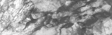
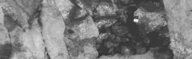
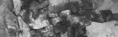
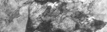
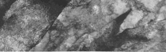
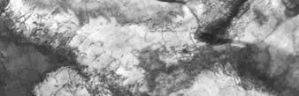
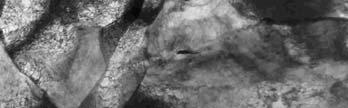
6 2µm Figure 8.16 Acicular ferrite morphology in alloy #5 after fast cooling of 47ºCs -1 after the hot rolling process
7 8.3 Nucleation of acicular ferrite Nucleation on non-metallic inclusions Both acicular ferrite and bainite have a lath-like structure when observed in thin foil samples by Transmission Electron Microscopy, i.e. both belong to a group of transformations that proceed basically by a displacive mechanism [139]. The main differences between the nucleation and growth of these two phases are the nucleation sites and the presence of cementite inside the laths or at inter-lath positions. Bainite nucleates on an austenite grain boundary [65,66,78], forming sheaves of parallel plates or laths with all essentially of the same crystallographic orientation. The boundaries and the general orientation of the plates are generally visible by optical microscopy (see figure 7.21-(k) in section 7.4 above). The nucleation of an acicular ferrite structure, on the other hand, generally occurs intragranularly and often on non-metallic inclusions [70,136] as found in weld pools. As described in section 8.4, the morphologies found in this study were either parallel laths (figure 8.13) or interwoven laths (figure 8.15). Such intricate structural features, however, could not be identified by optical microscopy (see figure 7.29 in section 7.9) because of a lack of resolution of visible boundaries [131,135,140]. No precipitation of cementite was also found by thin foil TEM between or within the laths of the acicular ferrite. Accordingly, the lath morphologies in the present work differ significantly from that of bainite. These differences stem basically from differences in their nucleation mechanisms. Such differences in nucleation sites between bainite and acicular ferrite formation were also found by other authors [65,66,78,134]. A reduction of the austenite grain boundary surface area per unit volume, favours the formation of acicular ferrite and is detrimental to the formation of bainite due to the decrease in the number of potential bainite nucleation sites [65] on the austenite grain boundaries. A similar result in enhancing acicular ferrite formation was achieved by increasing the quantity of inclusions in the steel [141]. It has, therefore, been generally accepted that inclusions are the favoured sites for the nucleation of acicular ferrite [53,54,84,141,142], at least in the case of weld pools. As described in section 8.3 above, the microstructures of the alloys studied here consisted in general of a mixture of acicular ferrite plus polygonal ferrite. An attempt
 on the TEM of the inclusion in figure 8.17-(a) showed that it consisted of manganese and iron oxides. The iron peak in figure 8.")


8 was made to find any non-metallic inclusions that existed within the laths. Figures 8.17 to 8.20 show acicular ferrite laths around such non-metallic inclusions. The analysis by Energy Dispersive Spectroscopy (EDS) on the TEM of the inclusion in figure 8.17-(a) showed that it consisted of manganese and iron oxides. The iron peak in figure 8.17-(b) was not thought to arise entirely from the steel matrix as the size of the inclusion of about 1.1 µm was large enough for the electron beam to strike primarily on the inclusion during the EDS analysis, although the beam had to penetrate through some matrix material to arrive at the inclusion. No diffraction pattern could be obtained on the TEM as the inclusion was too thick. The inclusion was centered inside the 50 to 80 µm thickness of the thin foil which made it even more difficult for the electron beam to transmit through the inclusion. Consequently, any information on the structure or molecular formula of the inclusion could not be obtained from a diffraction pattern. (a) 1 µm (b) Figure 8.17 (a) TEM image of acicular ferrite and a large non-metallic inclusion in alloy #5 after a rapid cooling rate of 47 ºCs -1 after the hot rolling, (b) EDS analysis on the inclusion in this figure (a)


 EDS analysis on the inclusion in this")
,")
9 A B (a) 1 µm (b) 2 µm (c) (d) (e) Figure 8.18 Laths nucleated on non-metallic inclusions (a) in alloy #1 after a rapid cooling rate of 47 ºCs -1 after the hot rolling, (b) in alloy #3 after a rapid cooling rate of 40 ºCs -1 from 980 ºC down to room temperature without deformation, (c) EDS analysis on the inclusion in this figure (a), (d) and (e) EDS analysis on the inclusions A and B in this figure (b), respectively
 Nucleation of interwoven laths of acicular ferrite")

, while")
10 (a) 2µm (b) Figure 8.19 (a) Nucleation of interwoven laths of acicular ferrite in sample #AF3F of alloy #3 after a cooling rate of 20 ºCs -1 from 980 ºC down to room temperature without deformation, (b) EDS analysis of red peak was from on the inclusion indicated by an arrow in this figure (a), while blue peak was from the matrix steel
")
")

11 (a) 1µm (b) Figure 8.20 (a) Non-metallic inclusion and acicular ferrite in alloy #3 after a rapid cooling rate of 47 ºCs -1 after the hot rolling, (b) EDS analysis on the inclusion indicated by an arrow in this figure (a)
12 Similar nucleation of laths of acicular ferrite on inclusions was also found in alloy #1 (figure 8.18-(a) above). The inclusions in this case were generally round in shape, with a size of about 1.2 µm. The EDS image in figure 8.18-(c) reveals that the composition of these inclusions was apparently a complex oxide containing silicon, aluminium and iron. University of Pretoria etd Tang, Z (2007) Further nucleation of acicular ferrite on non-metallic inclusions is shown in figure 8.18-(b) for sample #AF3F of alloy #3 (0.09% Mo) that was cooled at 40 ºCs -1 from 980ºC down to room temperature (figure 6.14 in section 6.9). The acicular ferrite had once more, a typical lath structure nucleated around non-metallic inclusions with rounded shapes. The diameter of the inclusions ranged from 1.9 µm to 2.2 µm (see figure 8.18-(b)). The EDS image in figure 8.18-(d) and (e) revealed that they were complex oxides containing silicon, aluminium and iron. From the figure it appears that the two primary parallel laths of acicular ferrite nucleated on the non-metallic inclusion. The secondary lath, however, nucleated at the tip of the primary one, possibly owing to a lower carbon content in this area and then grew in the same direction as the primary one. The nucleation of interlocked laths of acicular ferrite is shown in figure 8.19 for another sample in group #AF3F of alloy #3 (0.09% Mo) (figure 6.14 in section 6.9). The cooling rate was 20 ºCs -1 from 980 ºC down to room temperature. The inclusions were about 0.5 µm in diameter and, therefore, quite small to be analysed with confidence by EDS in the thin foil. The blue peak for iron in figure 8.19-(b) probably arose from the matrix of the steel surrounding the inclusion. There is a difference in the iron peak between the red and blue lines in the EDS image. Therefore, it appears that the non-metallic inclusion shown by an arrow in the figure was a mixture of manganese, iron and copper oxide. Figure 8.20 shows the nucleation of an acicular ferrite colony on an inclusion of about 0.35 µm in diameter. For such an inclusion, the iron peak in figure 8.20-(b) is probably from the steel matrix and not from the inclusion. Thus, the acicular ferrite nucleated on an inclusion consisting probably of manganese and copper sulphide
13 Summarising the results above, a number of inclusions were found that were associated with acicular ferrite laths. Previous researchers have also found that acicular ferrite nucleates on non-metallic inclusions [75,77,141] and their nucleation frequency increases with an increasing quantity of inclusions in a weld pool [141,143]. In this work the nucleation sites for acicular ferrite were generally oxide and sulphide inclusions with generally a rounded shape whereas the size of these inclusions ranged from 0.35 to 2.2 µm. The chemical compositions of these non-metallic inclusions were complex containing silicon, aluminium, iron, manganese and copper Type of non-metallic inclusion as nucleants Other researchers have reported that acicular ferrite nucleates on inclusions or particles, such as TiO [141,144,145], BN plus rare earth metal oxysulphides [148], aluminium-rich inclusions [147,148], and TiN [149]. Most of the work, however, focused on weld pools where a larger quantity of non-metallic inclusions is readily introduced. Bhatti [147] has reported that inclusions rich in manganese and inclusions covered by a skin of sulphide are ineffective nucleants for acicular ferrite. Inclusions which are covered by or are rich in copper-sulphur or silicon and which were effective as a nucleant [65,66,70] for acicular ferrite, however, were found by Zhang and Farrar [141], Dowling et al [144], Court [150], Harbottl [151], Madariaga [69] and Kayali et al [152]. Similar oxide inclusions of manganese plus iron and containing copper and also manganese sulphides containing copper have been found in this work (see figures 8.19 and 8.20 respectively). It may, therefore, be concluded that the type of inclusions that had formed nucleation sites for acicular ferrite in these steels studied here, were most likely complex oxides or sulphides Nucleation mechanisms of acicular ferrite Three nucleation mechanisms of acicular ferrite on inclusions have been proposed by previous researchers: (1) the existence of local variations in the chemistry of the matrix [90] ; (2) the generation of high strain fields around the inclusion due to the different thermal expansion coefficients between austenite and the inclusion [153,154] or deformation in the austenite region; and (3) the creation of a low energy interface between acicular ferrite and the inclusion owing to a low lattice mismatch between them [69, ]
14 When acicular ferrite is formed, the total system s Gibbs free energy must be lowered for the nucleus to become thermodynamically stable. This total energy includes the decrease in the chemical free energy, the disappearance of an interface between the inclusion and the austenite, and two new interfaces created of austenite-acicular ferrite and inclusion-acicular ferrite. This change in total energy can be described by the following equation: ΔG total = ΔG v V AF +σ AF/γ A AF/γ + σ AF/I A AF/I +ΔG ε V AF σ I/γ A I/γ ΔG defect V AF (8.1) where ΔG v is the decrease in Gibbs free energy per unit volume owing to the transformation from austenite to acicular ferrite, also often termed the chemical free energy, V AF is the volume of transformed acicular ferrite, σ AF/γ, σ AF/I, σ I/γ are interface energies per unit area between acicular ferrite and austenite, acicular ferrite and an inclusion and an inclusion and austenite, respectively; A AF/γ, A AF/I, A I/γ are the interface areas between acicular ferrite and austenite, acicular ferrite and an inclusion and, an inclusion and austenite, respectively, ΔG ε is the strain energy per unit volume around the new AF nucleus due to the volume expansion during the transformation from a face-centered cubic lattice (fcc) to a body-centered cubic lattice (bcc) and ΔG defect is the stored defect elastic energy per unit volume in austenite around the inclusion due to deformation in the austenite, such as dislocation or point defects. ΔG v V AF is the chemical Gibbs driving force for the transformation that is dependent on the degree of under-cooling of the austenite as well as the chemical composition of the austenite and is generally independent of the inclusions present in the austenite. σ AF/I A AF/I and σ I/γ A I/γ are only affected by inclusions where acicular ferrite nucleates and is primarily determined by the mismatch of the interface between acicular ferrite and an inclusion. The transformation will proceed more readily through an increasing absolute value of ΔG v V AF and become stable when the embryo size of acicular ferrite (r) reaches the critical size (r * ) (r * is determined according to dδg dr total =0). This driving force is increased by increasing the under-cooling ΔT which again is increased by a higher cooling rate on the rising part of the nose on a CCT diagram. That this
15 is so, is confirmed by the results shown on the CCT diagrams in figures 7.26 and 7.28 in section 7.5 where it was found that a faster cooling rate after deformation of the austenite is more favourable for acicular ferrite formation because the under-cooling increases with an increase in cooling rate. σ AF/γ A AF/γ, σ AF/I A AF/I and ΔG ε V AF are the barriers to the nucleation of AF. It means that low values of the surface energies σ AF/γ and σ AF/I are beneficial to the nucleation of acicular ferrite on inclusions. σ AF/γ is dependent on the crystal lattice mismatch between acicular ferrite and austenite and will, therefore, determine the crystallographic orientation of the laths. For instance, a low σ AF/γ will arise from a low lattice mismatch between them. In the present case where a lack of sufficient inclusions in the steels may occur, the typical acicular ferrite will be the parallel lath structure due to a low mismatch between austenite and acicular ferrite (also leading to a low σ AF/γ ) in this direction which is parallel to the primary one. σ AF/I, however, is dependent on the lattice structure of the inclusion. An inclusion that has a lower mismatch with an acicular ferrite nucleus, is favoured more to nucleate acicular ferrite. Some researchers [141,144,159] have observed that an inclusion with a manganese sulphide core covered by a skin of copper sulphide acts as a nucleant for acicular ferrite, instead of manganese sulphide only. Considering the surface energy σ I/γ between an inclusion and austenite only (which effectively becomes an additional driving force as it is removed from the system upon forming an acicular ferrite nucleus), on the other hand, this energy increases with an increase in their melting temperature [141]. The melting temperature is 1620 ºC for manganese sulphide, while it is 1125 ºC for copper sulphide [141], which means that σ MnS/ γ is higher than σ CuS/ γ, and this will result in manganese sulphide being a more effective nucleant than copper sulphide as it provides a higher additional driving force. However, Evans [160] has reported that a high lattice mismatch exists between
16 manganese sulphide and ferrite, leading to a high retarding force σ MnS/AF. Therefore, copper sulphide may be more favourable to nucleate acicular ferrite than manganese sulphide owing to the lower mismatch between it and the ferrite [65]. A similar inclusion has also been found in the present study in alloy #3 (see figure 8.20). It is believed that the inclusion may possibly also have been manganese sulphide in the core and copper sulphide on the outer skin although the difference between core and skin were not resolved by EDS owing to the small size of the inclusion. Accordingly, it can only be speculated that the surface layer of this inclusion may have been favourable for the nucleation of acicular ferrite as found by others for such types of inclusions. University of Pretoria etd Tang, Z (2007) As indicated above, σ I/γ A I/γ is another driving force for the transformation because of its negative sign. A high energy interface would preferably be replaced by a low energy one during the phase transformation, thus lowering the effective energy barrier for nucleation according to classical nucleation theory. Using the general assumption that the interface energy of phases or particles increase with their melting temperature, Dowling [144] has proposed that Al 2 O 3 and SiO 2 would be expected to have high interface energies. These inclusions would, therefore, be efficient nucleants for acicular ferrite. In this work some aluminium, silicon and manganese oxides were found within the acicular ferrite laths (see figures 8.17 to 8.19) which were effective nucleants because these inclusions are of higher melting temperatures, 2015 ºC for Al 2 O 3, 1713 ºC for SiO 2 and 1650 ºC for MnO [65]. The additional driving force ΔG defect arises from any defects in the austenite around inclusions from the deformation in the parent austenite during hot rolling below the T nr. Most of these defects are likely to be dislocations as point defects will probably already anneal out during the hot rolling, even below the T nr. The total strain in the finish rolling process below the T nr of 0.54 that was applied here, would have resulted in a relatively high dislocation density within the austenite at the point of deformation. Furthermore, the density of dislocations immediately around inclusions will be higher than further away because of a concentration in deformation behaviour in the austenite in those areas. That this is likely to occur, has been shown by a number of authors in the theory of Particle Stimulated Nucleation (PSN) around large
17 precipitates after cold working in aluminium alloys [97]. In the PSN theories [161,162], it has been shown that the deformation zones around large second phase particles contain a larger number of geometrically necessary dislocations than further away and this leads to a higher driving force for nucleation during recrystallisation at the surfaces of these particles. University of Pretoria etd Tang, Z (2007) Similar to the above case of PSN, a higher stored defect energy, therefore, possibly exists in the area of austenite around an inclusion than further away or in undeformed austenite. This stored energy provides an additional driving force for acicular ferrite nucleation. It also means that the nucleation barrier for acicular ferrite may be reduced in the strain and dislocation field around the inclusion, leading to the observation that deformation in the austenite accelerates the nucleation of acicular ferrite or generates suitable nucleation sites [134,141]. This point has been demonstrated clearly by the results of the strain affected CCT diagrams in this study, in which it was demonstrated in section 7.5 that deformation in the austenite is beneficial to acicular ferrite formation instead of bainite. ΔG ε V AF is another retarding force of strain energy due to the volume expansion during the transformation because there is a lattice change from fcc (austenite) to bcc (acicular ferrite). The amount of this strain energy is dependent on the temperature of the transformation and lower transformation temperatures will result in a higher strain energy because the untransformed austenite around acicular ferrite will strain harden more than at higher temperatures. Acicular ferrite, however, is a displacive transformation and it is also possible that defects in the austenite prior to the transformation that may promote the nucleation, can also retard the growth [76]. The nucleated primary laths formed around inclusions may, therefore, grow to a smaller size in deformed austenite (see figure 7.27 of alloy #5 in section 7.5) than in a well annealed austenite. This will result in an overall finer ferrite grain size after transformation. A coarse acicular ferrite microstructure was only observed in alloy #5 without prior deformation (figure 7.23 in section 7.4)
18 In summary, therefore, deformation in the austenite prior to the transformation appears to accelerate the nucleation of acicular ferrite and thereafter possibly limits its growth, so that the size of the formed acicular ferrite packets or grains becomes finer
University of Pretoria Z Tang (2006) Chapter 8 Studies of acicular ferrite by thin foil TEM CHAPTER 8 STUDIES OF ACICULAR FERRITE BY THIN FOIL TEM
 Chapter 8 Studies of acicular ferrite by thin foil TEM CHAPTER 8 STUDIES OF ACICULAR FERRITE BY THIN FOIL TEM") CHAPTER 8 STUDIES OF ACICULAR FERRITE BY THIN FOIL TEM 8.1 Acicular ferrite morphology in experimental alloys The optical micrographs in figure 7.29 for the alloys after rapid cooling at a rate of 47 ºCs
CHAPTER 8 STUDIES OF ACICULAR FERRITE BY THIN FOIL TEM 8.1 Acicular ferrite morphology in experimental alloys The optical micrographs in figure 7.29 for the alloys after rapid cooling at a rate of 47 ºCs
Effect of titanium additions to low carbon, low manganese steels on sulphide precipitation
 University of Wollongong Thesis Collections University of Wollongong Thesis Collection University of Wollongong Year 2008 Effect of titanium additions to low carbon, low manganese steels on sulphide precipitation
Case Study: Design of Bainitic Steels
 Materials Science & Metallurgy Part II Course C9, Alloys, H. K. D. H. Bhadeshia Case Study: Design of Bainitic Steels Bainite Summarised Bainite is a non lamellar aggregate of carbides and plate shaped
1. TRANSFORMATION PRODUCTS OF AUSTENITE
 1. TRANSFORMATION PRODUCTS OF AUSTENITE Classification of chapters: 1. Transformation products of austenite 1.1. Basic information about austenite and its phase transformation products 1.1.1. What is austenite
Phase Transformations in Metals Tuesday, December 24, 2013 Dr. Mohammad Suliman Abuhaiba, PE 1
 Ferrite - BCC Martensite - BCT Fe 3 C (cementite)- orthorhombic Austenite - FCC Chapter 10 Phase Transformations in Metals Tuesday, December 24, 2013 Dr. Mohammad Suliman Abuhaiba, PE 1 Why do we study
Part IV : Solid-Solid Phase Transformations I Module 3. Eutectoid transformations
 Part IV : Solid-Solid Phase Transformations I Module 3. Eutectoid transformations 3 Eutectoid transformations 3.1 Motivation What are the different microstructural features due to the eutectoid transformation
Continuous Cooling Diagrams
 Continuous Cooling Diagrams Isothermal transformation (TTT) diagrams are obtained by rapidly quenching to a given temperature and then measuring the volume fraction of the various constituents that form
Introduction to Heat Treatment. Introduction
 MME444 Heat Treatment Sessional Week 01 Introduction to Heat Treatment Prof. A.K.M.B. Rashid Department of MME BUET, Dhaka Introduction Can you control the microstructure that formed during cooling of
The effect of microstructure and processing variables on the yield to ultimate tensile strength ratio in a Nb Ti and a Nb Ti Mo line pipe steel
 The effect of microstructure and processing variables on the yield to ultimate tensile strength ratio in a Nb Ti and a Nb Ti Mo line pipe steel Zhenghua Tang a and Waldo Stumpf a a Department of Materials
Hot Deformation and Acicular Ferrite Microstructure in C Mn Steel Containing Ti 2 O 3 Inclusions
 , pp. 819 823 Hot Deformation and Acicular Ferrite Microstructure in C Mn Steel Containing Ti 2 O 3 Inclusions Jae-Hyeok SHIM, Jung-Soo BYUN, Young Whan CHO, 1) Young-Joo OH, 1) Jae-Dong SHIM 1) and Dong
MT 348 Outline No MECHANICAL PROPERTIES
 MT 348 Outline No. 1 2009 MECHANICAL PROPERTIES I. Introduction A. Stresses and Strains, Normal and Shear Loading B. Elastic Behavior II. Stresses and Metal Failure A. ʺPrincipal Stressʺ Concept B. Plastic
Engineering Materials
 Engineering Materials Heat Treatments of Ferrous Alloys Annealing Processes The term annealing refers to a heat treatment in which a material is exposed to an elevated temperature for an extended time
Binary Phase Diagrams - II
 Binary Phase Diagrams - II Note the alternating one phase / two phase pattern at any given temperature Binary Phase Diagrams - Cu-Al Can you spot the eutectoids? The peritectic points? How many eutectic
Module 32. Heat treatment of steel II. Lecture 32. Heat treatment of steel II
 Module 32 Heat treatment of steel II Lecture 32 Heat treatment of steel II 1 Keywords : Kinetics of pearlitic transformation, Johnsom Mehl Avrami equation, effect of carbon content on T T T diagram, bainite:
Tutorial 2 : Crystalline Solid, Solidification, Crystal Defect and Diffusion
 Tutorial 1 : Introduction and Atomic Bonding 1. Explain the difference between ionic and metallic bonding between atoms in engineering materials. 2. Show that the atomic packing factor for Face Centred
GRAIN GROWTH BEHAVIOUR OF NIOBIUM-ALLOYED DIRECT QUENCHED STEELS DURING SLAB REHEATING
 GRAIN GROWTH BEHAVIOUR OF NIOBIUM-ALLOYED DIRECT QUENCHED STEELS DURING SLAB REHEATING CASR-seminar 19.12.2013 Materials engineering laboratory/ Jaakko Hannula 2 CONTENT Introduction Purpose of the study/
A TEM investigation of the influence of nitrogen and cold working on the microstructure of solid solution annealed austenitic stainless steel (316L)
") Göteborg 2004-02-24 A TEM investigation of the influence of nitrogen and cold working on the microstructure of solid solution annealed austenitic stainless steel (316L) Introduction The purpose of this
Göteborg 2004-02-24 A TEM investigation of the influence of nitrogen and cold working on the microstructure of solid solution annealed austenitic stainless steel (316L) Introduction The purpose of this
27-301, Fall 02, Rollett. Total marks = 100 (20 per question). 1 st Homework, due Sept. 6th
. 1 st Homework, due Sept. 6th") 27-301, Fall 02, Rollett Total marks = 100 (20 per question). 1 st Homework, due Sept. 6th Notes/Answers The thermal histories asked for in this homework are not always unique defined so the homeworks
27-301, Fall 02, Rollett Total marks = 100 (20 per question). 1 st Homework, due Sept. 6th Notes/Answers The thermal histories asked for in this homework are not always unique defined so the homeworks
Schematic representation of the development of microstructure. during the equilibrium solidification of a 35 wt% Ni-65 wt% Cu alloy
 Schematic representation of the development of microstructure during the equilibrium solidification of a 35 wt% Ni-65 wt% Cu alloy At 1300 ºC (point a) the alloy is in the liquid condition This continues
Module 31. Heat treatment of steel I. Lecture 31. Heat treatment of steel I
 Module 31 Heat treatment of steel I Lecture 31 Heat treatment of steel I 1 Keywords : Transformation characteristics of eutectoid steel, isothermal diagram, microstructures of pearlite, bainite and martensite,
1P1b: Introduction to Microscopy
 1P1b: Introduction to Microscopy Central to the study and characterisation of metals and many other materials is the microscope, ranging from the magnification of, say, 1 to 35 in a simple stereo binocular
STRENGTHENING MECHANISM IN METALS
 Background Knowledge Yield Strength STRENGTHENING MECHANISM IN METALS Metals yield when dislocations start to move (slip). Yield means permanently change shape. Slip Systems Slip plane: the plane on which
Introduction to Materials Science
 EPMA Powder Metallurgy Summer School 27 June 1 July 2016 Valencia, Spain Introduction to Materials Science Prof. Alberto Molinari University of Trento, Italy Some of the figures used in this presentation
Each carbon atom causes a tetragonal distortion since the principal
 Ferrous alloys Fig. 1: Iron-carbon equilibrium phase diagram martensite start temperature or M S. The fraction of martensite increases with the undercooling below M S. The martensite in steels is supersaturated
Martensite Formation in Austempered Ductile Iron with Unidirectional and Cyclic Loading
 419 Martensite Formation in Austempered Ductile Iron with Unidirectional and Cyclic Loading R. Böschen, H. Bomas, P. Mayr, H. Vetters, Institut fur Werkstofftechnik, Bremen, PRC Introduction The purpose
INFLUENCE OF SECOND PHASE PARTICLES ON RECRYSTALLISATION OF COLD-ROLLED LOW CARBON MICROALLOYED STEELS DURING ISOTHERMAL ANNEALING
 INFLUENCE OF SECOND PHASE PARTICLES ON RECRYSTALLISATION OF COLD-ROLLED LOW CARBON MICROALLOYED STEELS DURING ISOTHERMAL ANNEALING Carlos Capdevila a, Tommy De Cock b, Carlos García-Mateo c, Francisca
Chapter 9 Heat treatment (This chapter covers selective sections in Callister Chap. 9, 10 &11)
") Chapter 9 Heat treatment (This chapter covers selective sections in Callister Chap. 9, 10 &11) Study theme outcomes: After studying this chapter, students should or should be able to: - know and understand
Chapter 9 Heat treatment (This chapter covers selective sections in Callister Chap. 9, 10 &11) Study theme outcomes: After studying this chapter, students should or should be able to: - know and understand
Chapter 10, Phase Transformations
 Chapter Outline: Phase Transformations Heat Treatment (time and temperature) Microstructure Kinetics of phase transformations Homogeneous and heterogeneous nucleation Growth, rate of the phase transformation
CHAPTER 6 METALLOGRAPHIC INVESTIGATIONS
 CHAPTER 6 METALLOGRAPHIC INVESTIGATIONS 6.1 Introduction Metallographic investigation plays an important role to establish the causes of failures and the service condition of a component. These investigations
Three stages: Annealing Textures. 1. Recovery 2. Recrystallisation most significant texture changes 3. Grain Growth
 Three stages: Annealing Textures 1. Recovery 2. Recrystallisation most significant texture changes 3. Grain Growth Cold worked 85% Cold worked 85% + stress relieved at 300 C for 1 hr Cold worked 85% +
Heat Treatment of Steels : Metallurgical Principle
 Heat Treatment of Steels : Metallurgical Principle Outlines: Fe ad Fe-Fe 3 C system Phases and Microstructure Fe-Fe 3 C Phase Diaram General Physical and Mechanical Properties of each Microstructure Usanee
Kinetics - Heat Treatment
 Kinetics - Heat Treatment Nonequilibrium Cooling All of the discussion up till now has been for slow cooling Many times, this is TOO slow, and unnecessary Nonequilibrium effects Phase changes at T other
Q-P PROCESSING OF HIGH-STRENGTH LOW-ALLOYED STEEL SHEETS
 Q-P PROCESSING OF HIGH-STRENGTH LOW-ALLOYED STEEL SHEETS Daniela HAUSEROVÁ a, Zbyšek NOVÝ b, Jaromír DLOUHÝ c, Petr MOTYČKA d a,b,c,d COMTES FHT a.s., Průmyslová 995, 334 41 Dobřany, Czech Republic, comtesfht@comtesfht.cz
CHAPTER SEVEN EXPERIMENTAL RESULTS EFFECT OF THE STEEL S COMPOSITION 7.1 EFFECT OF ANNEALING TREATMENT ON STEEL B
 CHAPTER SEVEN EXPERIMENTAL RESULTS EFFECT OF THE STEEL S COMPOSITION 7 7.1 EFFECT OF ANNEALING TREATMENT ON STEEL B In order to understand the precipitation behaviour of the Laves phase more precisely,
Learning Objectives. Chapter Outline. Solidification of Metals. Solidification of Metals
 Learning Objectives Study the principles of solidification as they apply to pure metals. Examine the mechanisms by which solidification occurs. - Chapter Outline Importance of Solidification Nucleation
OUTLINE. Dual phase and TRIP steels. Processing Microstructure Mechanical properties Damage mechanisms Strategies to improve strength and ductililty
 OUTLINE Dual phase and TRIP steels Processing Microstructure Mechanical properties Damage mechanisms Strategies to improve strength and ductililty DUAL PHASE STEELS With relatively straightforward thermomechanical
Lab Materials Science
 Institute for Micro- and Nanomaterials Lab Summer Term 2007 Group 9: Adelheid Grob & Sukhum Ruangchai & Brook Esseye lab on June, 21st 2007 1 Questions 1.1 What is the goal of metallographic sample preparation?
DURATINET COURSE - Testing Techniques for Structures Inspection LNEC Lisbon Portugal May 2012
 DURATINET - Testing Techniques for Structures Inspection METALLOGRAPHY AND FRACTOGRAPHY OF IRON AND STEEL M. J. Correia LNEC, Laboratório Nacional de Engenharia Civil, DM, Av. do Brasil, 101, 1700 066
Lecture 31-36: Questions:
 Lecture 31-36: Heat treatment of steel: T-T-T diagram, Pearlitic, Martensitic & Bainitic transformation, effect of alloy elements on phase diagram & TTT diagram, CCT diagram, Annealing, normalizing, hardening
PHYSICAL METALLURGY CHARACTERISTICS OF INCLUSIONS AND MICROSTRUCTURAL RESPONSE IN LOW CARBON STEELS
 PHYSICAL METALLURGY CHARACTERISTICS OF INCLUSIONS AND MICROSTRUCTURAL RESPONSE IN LOW CARBON STEELS FYZIKÁLNĚ METALURGICKÉ CHARAKTERISTIKY INKLUZÍ A MIKROSTRUKTURNÍ ODEZVA V NÍZKOUHLÍKOVÝCH OCELÍCH Eva
MTLS 4L04 Steel Section. Lecture 6
 MTLS 4L04 Steel Section Lecture 6 Tempering of Martensite To get around the problem of the brittleness of the Martensite, Martensite is heat treated at elevated temperatures (200-700 C) to precipitate
C Limited Metallurgical Examination
 Jonathan Barnett Ronald R. Biederman R. D. Sisson, Jr. C Limited Metallurgical Examination C.1 Introduction Two structural steel members with unusual erosion patterns were observed in the WTC debris field.
ME 254 MATERIALS ENGINEERING 1 st Semester 1431/ rd Mid-Term Exam (1 hr)
") 1 st Semester 1431/1432 3 rd Mid-Term Exam (1 hr) Question 1 a) Answer the following: 1. Do all metals have the same slip system? Why or why not? 2. For each of edge, screw and mixed dislocations, cite
1 st Semester 1431/1432 3 rd Mid-Term Exam (1 hr) Question 1 a) Answer the following: 1. Do all metals have the same slip system? Why or why not? 2. For each of edge, screw and mixed dislocations, cite
CHAPTER INTRODUCTION
 1 CHAPTER-1 1.0 INTRODUCTION Contents 1.0 Introduction 1 1.1 Aluminium alloys 2 1.2 Aluminium alloy classification 2 1.2.1 Aluminium alloys (Wrought) 3 1.2.2 Heat treatable alloys (Wrought). 3 1.2.3 Aluminum
Master examination. Metallic Materials
 Master examination Metallic Materials 01.03.2016 Name: Matriculation number: Signature: Task Points: Points achieved: 1 13 2 4 3 3 4 6 5 6 6 3 7 4 8 9 9 6 10 9.5 11 8 12 8 13 10.5 14 4 15 6 Sum 100 Points
Three-Dimensional Atom Probe Analysis of Carbon Distribution in Low-Temperature Bainite
 Three-Dimensional Atom Probe Analysis of Carbon Distribution in Low-Temperature Bainite M. Peet *, S. S. Babu, M. K. Miller and H. K. D. H. Bhadeshia * * Department of Materials Science and Metallurgy,
STRAIN-INDUCED STABILISATION OF AUSTENITE AGAINST BAINITE TRANSFORMATION
 STRAIN-INDUCED STABILISATION OF AUSTENITE AGAINST BAINITE TRANSFORMATION S. B. Singh 1 and H. K. D. H. Bhadeshia 2 1 Indian Institute of Technology, Kharagpur, India 2 University of Cambridge, UK S. B.
Physical Metallurgy Friday, January 28, 2011; 8:30 12:00 h
 Physical Metallurgy Friday, January 28, 2011; 8:30 12:00 h Always motivate your answers All sub-questions have equal weight in the assessment Question 1 Precipitation-hardening aluminium alloys are, after
Microstructural characterisation of as-deposited and reheated weld metal High Strength Steel Weld Metals
 Microstructural characterisation of as-deposited and reheated weld metal High Strength Steel Weld Metals Enda Keehan, Leif Karlsson, Mattias Thuvander, Eva-Lena Bergquist Abstract ESAB AB, Gothenburg,
MICROSTRUCTURE CHARACTERIZATION OF GOES AFTER HOT ROLLING AND COLD ROLLING + DECARBURIZATION ANNEALING
 MICROSTRUCTURE CHARACTERIZATION OF GOES AFTER HOT ROLLING AND COLD ROLLING + DECARBURIZATION ANNEALING Vlastimil VODÁREK 1, Jan HOLEŠINSKÝ 1, Anastasia MASLOVA 1, František FILUŠ 1, Šárka MIKLUŠOVÁ 2,
Hypoeutectoid Carbon Steels. Hypereutectoid Carbon Steels
 Hypoeutectoid Carbon Steels Another example: Amount of carbon? 1035 Steel: white regions are proeutectoid ferrite grains By the end of this lecture you should be able to predict the amount of carbon in
An Investigation of Microstructural Change of Low Alloy Steel AISI 4150 by Seebeck Coefficient
 Journal of Metals, Materials and Minerals, Vol.0 No.1 pp.1-6, 010 An Investigation of Microstructural Change of Low Alloy Steel AISI 4150 by Seebeck Coefficient Teerapong SAMRAN 1 and Preecha TERMSUKSAWAD
Diffusional Transformations in Solids
 Diffusional Transformations in Solids The majority of phase transformations that occur in the solid state take place by thermally activated atomic movements. The transformations that will be dealt with
Study on the enameling properties of cold-rolled sheet steels contained different alloyed elements
 Study on the enameling properties of cold-rolled sheet steels contained different alloyed elements SUN Quanshe, XU Chun 2 ) R & D Center, Baoshan Iron and Steel Co. Ltd., Shanghai 29, China 2) School of
Iranian Journal of Materials Science & Engineering Vol. 7, Number 1, Winter 2010
 Iranian Journal of Materials Science & Engineering Vol. 7, Number 1, Winter 2010 THE EFFECT OF COOLING RATE AND AUSTENITE GRAIN SIZE ON THE AUSTENITE TO FERRITE TRANSFORMATION TEMPERATURE AND DIFFERENT
Strengthening Mechanisms
 ME 254: Materials Engineering Chapter 7: Dislocations and Strengthening Mechanisms 1 st Semester 1435-1436 (Fall 2014) Dr. Hamad F. Alharbi, harbihf@ksu.edu.sa November 18, 2014 Outline DISLOCATIONS AND
Bimodal Size-distribution of Bainite Plates
 Materials Science and Engineering, Vol. A438-440, 2006,145-148 Bimodal Size-distribution of Bainite Plates K. Hase a), C. Garcia-Mateo b), and H. K. D. H. Bhadeshia c) a) JFE Steel Corporation, Steel Research
Principles of Physical Metallurgy Prof. R. N. Ghosh Department of Metallurgical and Materials Engineering Indian Institute of Technology, Kharagpur
 Principles of Physical Metallurgy Prof. R. N. Ghosh Department of Metallurgical and Materials Engineering Indian Institute of Technology, Kharagpur Lecture No. # 34 Heat Treatment of Steel (Contd.) (Refer
Material Degradation of Nuclear Structures Mitigation by Nondestructive Evaluation
 Material Degradation of Nuclear Structures Mitigation by Nondestructive Evaluation 17 MnMoV 6 4 (WB35): Stretched Zone Material Degradation of Nuclear Structures Mitigation by Nondestructive Evaluation
Solidification and Crystallisation 5. Formation of and control of granular structure
 MME 345 Lecture 08 Solidification and Crystallisation 5. Formation of and control of granular structure Ref: [1] A. Ohno, The Solidification of Metals, Chijin Shokan Co. Ltd., 1976 [2] P. Beeley, Foundry
AFFECT OF CEMENTITE PRECIPITATION ON THE EXTEND OF BAINITE REACTION IN ADI
 AFFECT OF CEMENTITE PRECIPITATION ON THE EXTEND OF BAINITE REACTION IN ADI Zdzisław Ławrynowicz University of Technology and Life Sciences, Mechanical Engineering Faculty Department of Materials Science
Solid State Transformations
 Solid State Transformations Symmetrical Tilt Boundary The misorientation θ between grains can be described in terms of dislocations (Fig. 1). Inserting an edge dislocation of Burgers vector b is like forcing
Lecture 20: Eutectoid Transformation in Steels: kinetics of phase growth
 Lecture 0: Eutectoid Transformation in Steels: kinetics of phase growth Today s topics The growth of cellular precipitates requires the portioning of solute to the tips of the precipitates in contact with
Toughness and Microstructure of Coarse Grain Heat Affected Zone with High Heat Input Welding in Zr-bearing Low Carbon Steel
 , pp. 188 192 Toughness and Microstructure of Coarse Grain Heat Affected Zone with High Heat Input Welding in Zr-bearing Low Carbon Steel Minghao SHI,* Pengyan ZHANG and Fuxian ZHU State Key Laboratory
Effect of Thermomechanical Processing on the Microstructure and Properties of a Low Carbon Copper Bearing Steel
 , pp. 257 261 Effect of Thermomechanical Processing on the Microstructure and Properties of a Low Carbon Copper Bearing Steel M. K. BANERJEE, P. S. BANERJEE and S. DATTA Department of Metallurgy, B. E.
Chapter 10: Phase Transformations
 Chapter 10: Phase Transformations ISSUES TO ADDRESS... Transforming one phase into another takes time. Fe C FCC (Austenite) Eutectoid transformation Fe 3 C (cementite) + (ferrite) (BCC) How does the rate
Development of bimodal grain structures in microalloyed steels:
 Development of bimodal grain structures in microalloyed steels: Niobium and titanium are added to high strength low alloy (HSLA) steels to provide grain boundary pinning precipitates to help produce the
CHAPTER 3 SELECTION AND PROCESSING OF THE SPECIMEN MATERIAL
 54 CHAPTER 3 SELECTION AND PROCESSING OF THE SPECIMEN MATERIAL 3.1 HIGH STRENGTH ALUMINIUM ALLOY In the proposed work, 7075 Al alloy (high strength) has been identified, as a material for the studies on
Effects of Coiling Temperature on Microstructure and Mechanical Properties of High-strength Hot-rolled Steel Plates Containing Cu, Cr and Ni
 , pp. 692 698 Effects of Coiling Temperature on Microstructure and Mechanical Properties of High-strength Hot-rolled Steel Plates Containing Cu, Cr and Ni Sung-Joon KIM, Chang Gil LEE, Tae-Ho LEE and Sunghak
Microstructure and phase transformations in alloy steels and simulations of their processing
 AEDS 2004 WORKSHOP 11 12 November 2004, Pilsen - Czech Republic Microstructure and phase transformations in alloy steels and simulations of their processing D. Jandová, V. ernášek, H. Paterová and D. Kešner
Refinement Mechanism of Heat-Affected Zone Microstructures on TiO Steels
 Technical Report UDC 669. 14. 018. 292 : 621. 791. 053 : 539. 55 Refinement Mechanism of Heat-Affected Zone Microstructures on TiO Steels Shunsuke TANIGUCHI* Genichi SHIGESATO Abstract Nippon Steel & Sumitomo
Chapter 10: Phase Transformations
 Chapter 10: Phase Transformations ISSUES TO ADDRESS... Transforming one phase into another takes time. Fe (Austenite) Eutectoid transformation Fe 3 C (cementite) + C FCC (ferrite) (BCC) How does the rate
Chapter 1. Iron-Carbon AlloysⅠ. /MS371/ Structure and Properties of Engineering Alloys
 Chapter 1 Iron-Carbon AlloysⅠ Iron pure iron : to be obtained through zone refining adding a small amount of C, Mn, P, S 증가 pure iron 의 allotropic forms Allotropic forms Crystallographic form Unit cube
Lecture 12: High Temperature Alloys
 Part IB Materials Science & Metallurgy H. K. D. H. Bhadeshia Course A, Metals and Alloys Lecture 12: High Temperature Alloys Metallic materials capable of operating at ever increasing temperatures are
Module 29. Precipitation from solid solution I. Lecture 29. Precipitation from solid solution I
 Module 29 Precipitation from solid solution I Lecture 29 Precipitation from solid solution I 1 Keywords : Properties of two phase alloys, super saturated solid solutions, historical perspective, solution
Wrought Aluminum I - Metallurgy
 Wrought Aluminum I - Metallurgy Northbrook, IL www.imetllc.com Copyright 2015 Industrial Metallurgists, LLC Course learning objectives Explain the composition and strength differences between the alloy
Steels Processing, Structure, and Performance, Second Edition Copyright 2015 ASM International G. Krauss All rights reserved asminternational.
 Steels Processing, Structure, and Performance, Second Edition Copyright 2015 ASM International G. Krauss All rights reserved asminternational.org Contents Preface to the Second Edition of Steels: Processing,
Part IV. Solid-solid transformations I
 Part IV : Solid-Solid Phase Transformations I Module 1 : Precipitation Part IV. Solid-solid transformations I In this part, we discuss a few of the important solid-solid transformations, namely, precipitation,
Precipitation Hardening. Outline. Precipitation Hardening. Precipitation Hardening
 Outline Dispersion Strengthening Mechanical Properties of Steel Effect of Pearlite Particles impede dislocations. Things that slow down/hinder/impede dislocation movement will increase, y and TS And also
Strengthening Mechanisms
 Strengthening Mechanisms The ability of a metal/ alloy to plastically deform depends on the ability of dislocations to move. Strengthening techniques rely on restricting dislocation motion to render a
Kinetics of austenite formation during continuous heating in a low carbon steel
 Materials Characterization 58 (2007) 256 261 Kinetics of austenite formation during continuous heating in a low carbon steel F.L.G. Oliveira a, M.S. Andrade b, A.B. Cota c, a REDEMAT, Federal University
Heat Treating Basics-Steels
 Heat Treating Basics-Steels Semih Genculu, P.E. Steel is the most important engineering material as it combines strength, ease of fabrication, and a wide range of properties along with relatively low cost.
POSCO Lectures: The Bainite Reaction
 POSCO Lectures: The Bainite Reaction H. K. D. H. Bhadeshia, GIFT, POSTECH 1 Introduction Examination of a time temperature transformation (TTT) diagram for an eutectoid carbon steel (Fig. 1), bearing in
HEAT TREATMENT. Bulk and Surface Treatments Annealing, Normalizing, Hardening, Tempering Hardenability
 Bulk and Surface Treatments Annealing, Normalizing, Hardening, Tempering Hardenability HEAT TREATMENT With focus on Steels Principles of Heat Treatment of Steels Romesh C Sharma New Age International (P)
UNIT-II PART- A Heat treatment Annealing annealing temperature Normalizing.
 UNIT-II PART- A 1. What is "critical cooling rate" in hardening of steels? This critical cooling rate, when included on the continuous transformation diagram, will just miss the nose at which the pearlite
Phases transformation textures in steels
 J. Phys. IV France 0 (004) 37-44 EDP Sciences, Les Ulis DOI: 0.05/jp4:004005 Phases transformation textures in steels C. Cabus,, H. Regle and B. Bacroix IRSID-CMC, Voie Romaine, BP. 3030, 5783 Maizières-lès-Metz
Eva Mazancová a Zdeňka Rucká a Karel Mazanec a
 CONTRIBUTION OF ACICULAR FERRITE TO THE INCREASED HYDROGEN RESISTANCE OF LOW ALLOY STEEL PŘÍNOS ACIKULÁRNÍHO FERITU KE ZVÝŠENÍ ODOLNOSTI PROTI PŮSOBENÍ VODÍKU V NÍZKOLEGOVANÝCH OCELÍCH Eva Mazancová a
Microstructural effects of phase transformations Marek Faryna
 Microstructural effects of phase transformations Marek Faryna Institute of Metallurgy and Materials Science m.faryna@imim.pl 012 2952828 mobile 697 225 186 Outline Transformation in solids Formal theories
Strain-Induced Transformation of Very Strong Metal
 Strain-Induced Transformation of Very Strong Metal Mohamed Youssef Sherif St Edmund s College University of Cambridge Department of Materials Science and Metallurgy Pembroke Street, Cambridge CB2 3QZ A
The effect of cooling rate and coiling temperature on the niobium retention in ultrathin castrip steel
 University of Wollongong Research Online University of Wollongong Thesis Collection 1954-2016 University of Wollongong Thesis Collections 2016 The effect of cooling rate and coiling temperature on the
3. Solidification & Crystalline Imperfections
 3. Solidification & Crystalline Imperfections solidification (casting process) of metals divided into two steps (1) nucleation formation of stable nuclei in the melt (2) growth of nuclei into crystals
Bainite Transformation at Atomic Scale
 CENTRO NACIONAL DE INVESTIGACIONES METALÚRGICAS (CENIM) Bainite Transformation at Atomic Scale Francisca G. Caballero 1, M.K. Miller 2, C. Garcia-Mateo 1 and J. Cornide 1 1 Spanish National Research Center
MICROMECHANISMS OF CLEAVAGE FRACTURE IN THE HAZ OF C-MN COMMERCIAL STEEL WELD
 MICROMECHANISMS OF CLEAVAGE FRACTURE IN THE HAZ OF C-MN COMMERCIAL STEEL WELD C. Moya-Gutiérrez, A. Martín-Meizoso, I. Ocaña-Arizcorreta CEIT, Centro de Estudios e Investigaciones Técnicas de Guipúzcoa
NATURE OF PLASTIC DEFORMAIION
 NATURE OF PLASTIC DEFORMAIION Plastic deformation is the deformation which is permanent and beyond the elastic range of the material often, metals are worked by plastic deformation because of the beneficial
Dislocations Linear Defects
 Dislocations Linear Defects Dislocations are abrupt changes in the regular ordering of atoms, along a line (dislocation line) in the solid. They occur in high density and are very important in mechanical
Effect of zirconium addition on the recrystallization behaviour of a commercial Al Cu Mg alloy
 Bull. Mater. Sci., Vol. 4, No. 6, December 001, pp. 643 648. Indian Academy of Sciences. Effect of zirconium addition on the recrystallization behaviour of a commercial Al Cu Mg alloy K T KASHYAP Department
Practical 2P8 Transmission Electron Microscopy
 Practical 2P8 Transmission Electron Microscopy Originators: Dr. M. L. Jenkins and Prof. J. M. Titchmarsh What you should learn from this practical Science This practical ties-in with the lecture course
Recrystallization textures in metals and alloys
 Recrystallization textures in metals and alloys Uniaxial deformation Aluminium wire F.C.C. Metals and alloys FCC wires retain deformation texture ([111]+[100]) upon recrystallisation Composition / Purity
MSE-226 Engineering Materials
 MSE-226 Engineering Materials Lecture-4 THERMAL PROCESSING OF METALS-2 CONTINUOUS COOLING TRANSFORMATION (CCT) DIAGRAMS: In industrial heat-treating operations, in most cases a steel is not isothermally
The role of alloying elements in bainitic rail steels
 The role of alloying elements in bainitic rail steels by A. Kapito*, W. Stumpf, and M.J. Papo* Synopsis The formation of bainite in steel is dependent on the size of the casting, the heat treatment, and