STRUCTURE OF MATERIALS The Key to its Properties A Multiscale Perspective
|
|
|
- Katrina Page
- 6 years ago
- Views:
Transcription

1 STRUCTURE OF MATERIALS The Key to its Properties A Multiscale Perspective Anandh Subramaniam Materials and Metallurgical Engineering INDIAN INSTITUTE OF TECHNOLOGY KANPUR Kanpur anandh@iitk.ac.in Jan 2009
2 Properties of Materials The Scale of Microstructures Crystal Structures + Defects Microstructure OUTLINE With Examples from the Materials World
3 PROPERTIES Structure sensitive E.g. Yield stress, Fracture toughness Structure Insensitive E.g. Density, Elastic Modulus Structure Microstructure

4 What determines the properties? Cannot just be the composition! Few 10s of ppm of Oxygen in Cu can degrade its conductivity Cannot just be the amount of phases present! A small amount of cementite along grain boundaries can cause the material to have poor impact toughness Cannot just be the distribution of phases! Dislocations can severely weaken a crystal Cannot just be the defect structure in the phases present! The presence of surface compressive stress toughens glass [1] Composition Phases & Their Distribution Defect Structure Residual Stress [1] Metals Handbook, Vol.8, 8 th Edition, ASM, 1973
5 Length Scales Involved Nucleus Atom Crystal Microstructure Component Defects Angstroms Dislocation Stress fields Nanometers Microns Unit Cell * Crystalline Defects Microstructure Component Grain Size Centimeters *Simple Unit Cells
6 Crystal Thermo-mechanical Treatments Casting Metal Forming Welding Powder Processing Machining Atom Structure Microstructure Component Electromagnetic Phases + Defects Avoid Stress Concentrators Good Surface Finish Crystalline Quasicrystalline Amorphous Ferromagnetic Ferroelectric Superconducting Structure based Property based Vacancies Dislocations Twins Stacking Faults Grain Boundaries Voids Cracks + Residual Stress Processing determines shape and microstructure of a component
7 Crystal Thermo-mechanical Treatments Casting Metal Forming Welding Powder Processing Machining Atom Structure Microstructure Component Electromagnetic Crystalline Quasicrystalline Amorphous Ferromagnetic Ferroelectric Superconducting Phases + & their distribution Structure based Property based Defects Vacancies Dislocations Twins Stacking Faults Grain Boundaries Voids Cracks Avoid Stress Concentrators Good Surface Finish + Residual Stress Processing determines shape and microstructure of a component
8 METAL SEMI-METAL SEMI-CONDUCTOR INSULATOR BAND STRUCTURE ATOMIC STATE / VISCOSITY GAS SOLID LIQUID LIQUID CRYSTALS STRUCTURE AMORPHOUS QUASICRYSTALS RATIONAL APPROXIMANTS CRYSTALS SIZE NANO-QUASICRYSTALS NANOCRYSTALS
9 Crystal Atom Structure Microstructure Component Electromagnetic Why is BCC Iron the stable form of Iron at room temperature and not the FCC form of Iron? 1 Atm G vs T showing regions of stability of FCC and BCC Iron (Computed using thermo-calc software and database developed at the Royal Institute of Technology, Stockholm) The Structure of Materials, S.M. Allen & E.L. Thomas, John Wiley & Sons, Inc. New York, 1999.
10 This functional definition of microstructure includes all lengthscales Microstructure Phases + Defects Vacancies Dislocations Twins Stacking Faults Grain Boundaries Voids Cracks + Residual Stress
11 Microstructure Phases + Defects + Residual Stress Vacancies Dislocations Twins Stacking Faults Grain Boundaries Voids Cracks
12 Microstructure Phases + Defects + Residual Stress Vacancies Dislocations Twins Stacking Faults Grain Boundaries Voids Cracks Defects (Crystalline) Microstructural Vacancies Dislocations Phase Transformation Voids Cracks Component Stress corrosion cracking + Residual Surface Compressive Stress
13 CRYSTAL STRUCTURES
 + Motif (What to")


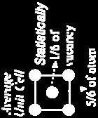
14 Crystal = Lattice (Where to repeat) + Motif (What to repeat) + = Unit cell of BCC lattice Crystal = Space group (how to repeat) + Asymmetric unit (Motif : what to repeat)
15 Progressive lowering of symmetry amongst the 7 crystal systems Increasing symmetry Cubic Hexagonal Tetragonal Trigonal Orthorhombic Monoclinic Triclinic Arrow marks lead from supergroups to subgroups
 Body")
 - FCC [2]")


![Octahedron) Pyrite Cube [1]](/docs-images/74/71193055/images/16-4.jpg "[1] Garnet Dodecahedron [1]")
![Fluorite Octahedron [1]](/docs-images/74/71193055/images/16-5.jpg "http://www.yourgemologist.")
![com/crystalsystems.html [2] L.](/docs-images/74/71193055/images/16-6.jpg "E. Muir, Interfacial")
16 1. Cubic Crystals a = b= c = = = 90º Simple Cubic (P) Body Centred Cubic (I) BCC Face Centred Cubic (F) - FCC [2] Point groups 23, 43m, m3, 432, 4 m 3 2 m Vapor grown NiO crystal Tetrakaidecahedron (Truncated Octahedron) Pyrite Cube [1] [1] Garnet Dodecahedron [1] Fluorite Octahedron [1] [2] L.E. Muir, Interfacial Phenomenon in Metals, Addison-Wesley Publ. co.
17 Crystals and Properties (The symmetry of) Any physical property of a crystal has at least the symmetry of the crystal Crystals are anisotropic with respect to most properties The growth shape of a (well grown) crystal has the internal symmetry of the crystal Polycrystalline materials or aggregates of crystals may have isotropic properties (due to averaging of may randomly oriented grains) The properties of a crystal can be drastically altered in the presence of defects (starting with crystal defects)
18 CLASSIFICATION OF DEFECTS BASED ON DIMENSIONALITY 0D (Point defects) 1D (Line defects) 2D (Surface / Interface) 3D (Volume defects) Vacancy Dislocation Surface Twins Impurity Disclination Interphase boundary Precipitate Frenkel defect Dispiration Grain boundary Faulted region Schottky defect Twin boundary Stacking faults Voids / Cracks Thermal vibration Anti-phase boundaries
19 0D (Point defects)
20 Non-ionic crystals Vacancy Impurity Interstitial Substitutional 0D (Point defects) Ionic crystals Frenkel defect Schottky defect Other ~ Imperfect point-like regions in the crystal about the size of 1-2 atomic diameters
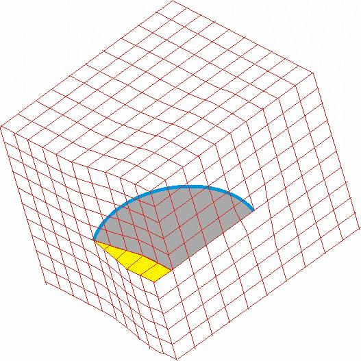
21 Vacancy Missing atom from an atomic site Atoms around the vacancy displaced Tensile stress field produced in the vicinity Tensile Stress Fields
22 Impurity Interstitial Substitutional Relative size Compressive Stress Fields Compressive stress fields SUBSTITUTIONAL IMPURITY Foreign atom replacing the parent atom in the crystal E.g. Cu sitting in the lattice site of FCC-Ni INTERSTITIAL IMPURITY Foreign atom sitting in the void of a crystal E.g. C sitting in the octahedral void in HT FCC-Fe Tensile Stress Fields
23 Interstitial C sitting in the octahedral void in HT FCC-Fe r Octahedral void / r FCC atom = r Fe-FCC = 1.29 Å r Octahedral void = x 1.29 = 0.53 Å r C = 0.71 Å Compressive strains around the C atom Solubility limited to 2 wt% (9.3 at%) Interstitial C sitting in the octahedral void in LT BCC-Fe r Tetrahedral void / r BCC atom = 0.29 r C = 0.71 Å r Fe-BCC = Å r Tetrahedral void = 0.29 x = Å But C sits in smaller octahedral void- displaces fewer atoms Severe compressive strains around the C atom Solubility limited to wt% (0.037 at%)
24 Equilibrium Concentration of Vacancies Formation of a vacancy leads to missing bonds and distortion of the lattice The potential energy (Enthalpy) of the system increases Work required for the formaion of a point defect Enthalpy of formation ( H f ) [kj/mol or ev/defect] Though it costs energy to form a vacancy its formation leads to increase in configurational entropy above zero Kelvin there is an equilibrium number of vacancies G = H T S SConfig kln( ) Crystal Kr Cd Pb Zn Mg Al Ag Cu Ni kj / mol ev / vacancy
25 G (perfect crystal) T (ºC) n/n G (Gibbs free energy) G min Equilibrium concentration H f x x x x 10 3 = 1 ev/vacancy = 0.16 x J/vacancy n (number of vacancies) Certain equilibrium number of vacancies are preferred at T > 0K Vacancies play a role in: Diffusion Climb Electrical conductivity Creep etc.
26 1D (Line defects)
27 The shear modulus of metals is in the range GPa m G 2 The theoretical shear stress will be in the range 3 30 GPa Actual shear stress is MPa I.e. (Shear stress) theoretical > 100 * (Shear stress) experimental!!!! DISLOCATIONS Dislocations weaken the crystal
28 DISLOCATIONS EDGE MIXED SCREW Usually dislocations have a mixed character and Edge and Screw dislocations are the ideal extremes
29 Conservative (Glide) Motion of dislocations On the slip plane Motion of Edge dislocation Non-conservative (Climb) Motion of dislocation to the slip plane For edge dislocation: as b t they define a plane the slip plane Climb involves addition or subtraction of a row of atoms below the half plane +ve climb = climb up removal of a plane of atoms ve climb = climb down addition of a plane of atoms
30 Mixed dislocations b t b Pure screw Pure Edge
31 Role of Dislocations Slip Fracture Fatigue Creep Diffusion (Pipe) Structural Creep mechanisms in crystalline materials Cross-slip Dislocation climb Vacancy diffusion Grain boundary sliding Incoherent Twin Grain boundary (low angle) Semicoherent Interfaces Disc of vacancies ~ edge dislocation
32 2D (Surface / Interface)
33 Grain Boundary The grain boundary region may be distorted with atoms belonging to neither crystal The thickness may be of the order of few atomic diameters The crystal orientation changes abruptly at the grain boundary In an low angle boundary the orientation difference is < 10º In the low angle boundary the distortion is not so drastic as the high-angle boundary can be described as an array of dislocations Grain boundary energy is responsible for grain growth on heating ~ (>0.5T m ) Large grains grow at the expense of smaller ones The average no. of nearest neighbours for an atom in the grain boundary of a close packed crystal is 11
34 Type of boundary Energy (J/m 2 ) Grain boundary between BCC crystals 0.89 Grain boundary between FCC crystals 0.85 Interface between BCC and FCC crystals 0.63 Grain boundaries in SrTiO 3
 Twin [1] Annealing")
35 Twin Boundary The atomic arrangement on one side of the twin boundary is related to the other side by a symmetry operation (usually a mirror) Mirror twin boundaries usually occur in pairs such that the orientation difference introduced by one is restored by the other The region between the regions is called the twinned region Annealing twins (formed during recrystallization) Twin [1] Annealing twins in Austenitic Stainless Steel Deformation twins (formed during plastic deformation) [1] Transformations in Metals, Paul G. Shewmon,McGraw-Hill Book Company, New York, 1969.

36 Twin boundary in Fe doped SrTiO 3 bicrystals (artificially prepared) High-resolution micrograph Mirror related variants Twin plane [1] S. Hutt, O. Kienzle, F. Ernst and M. Rühle, Z Metallkd, 92 (2001) 2
37 Grain size and strength y k i d Hall-Petch Relation y Yield stress i Stress to move a dislocation in single crystal k Locking parameter (measure of the relative hardening contribution of grain boundaries) d Grain diameter
38 Defects: Further Enquiry
39 DEFECTS Based on origin Random Structural Vacancies Dislocations Ledges The role played by a random defect is very different from the role played by a structural defect in various phenomenon
40 Low Angle Grain Boundaries b 2 2h


41 ~8º TILT BOUNDARY IN SrTiO 3 POLYCRYSTAL No visible Grain Boundary Å Dislocation structures at the Grain boundary Fourier filtered image
42 DEFECTS Based on position Random Ordered Vacancies Stacking Faults Ordered defects become part of the structure and hence affect the basic symmetry of the structure


43 Crystal with vacancies Vacancy ordering E.g. V 6 C 5, V 8 C 7

 x")


44 Effect of Atomic Level Residual Stress Yield Point Phenomenon y (Å) x (Å) (GPa) Interaction of the stress fields of dislocations with Interstitial atoms
45 3D (Volume defects) & MICROSTRUCTURES

 a GP-zone two Cu layers thick can chemically be identified. T.J.")
46 Bright field TEM micrograph of an Al- 3.3% Cu alloy, aged at room temperature for 100 days, showing the GP-I zones. HAADF micrographs of the GP zones: (a) Intercalated monatomic Cu layers several nm in width are clearly resolved, (b) a GP-zone two Cu layers thick can chemically be identified. T.J. Konno, K. Hiraga and M. Kawasaki, Scripta mater. 44 (2001)
47 b Precipitate particle b Hardening effect Increase in surface area due to particle shearing Part of the dislocation line segment (inside the precipitate) could face a higher PN stress
48 Pinning effect of the precipitate Can act like a Frank-Reed source ~ Gb 2r
49 Controlling microstructures: Examples

 BCC Cementite (Fe 3 C) Orthorhombic [1] Fe 0.16 0.8 4.")
50 Fe-Cementite diagram Eutectic L + Fe 3 C Peritectic L ºC L + L Fe 3 C ºC Eutectoid + Fe 3 C T + Fe 3 C Austenite ( ) FCC 723ºC Ferrite ( ) BCC Cementite (Fe 3 C) Orthorhombic [1] Fe Fe 3 C 6.7 %C [1] rruff.geo.arizona.edu/doclib/zk/vol74/zk74_534.pdf


![8, 8 th edition, ASM, Metals Park, Ohio T 400 [2] Bainite 300 200 M s](/docs-images/74/71193055/images/51-3.jpg "Austenite 348 C [1] 100 M f Martensite 0.")
![1 1 10 10 2 10 3 10 4 10 5 t (s) [2] Introduction to Physical](/docs-images/74/71193055/images/51-4.jpg "Metallurgy, S.H.")
51 Time- Temperature-Transformation (TTT) Curves Isothermal Transformation Eutectoid steel (0.8%C) Eutectoid temperature Austenite Pearlite Coarse Fine 500 Pearlite + Bainite Metals Handbook, Vol.8, 8 th edition, ASM, Metals Park, Ohio T 400 [2] Bainite M s Austenite 348 C [1] 100 M f Martensite t (s) [2] Introduction to Physical Metallurgy, S.H. Avner, McGraw-Hill Book Company, 1974 [2] 278 C [1] Physical Metallurgy for Engineers, D S Clark and W R Varney, Affiliated EastWest Press Pvt. Ltd., New Delhi, 1962 [1]
52 Time- Temperature-Transformation (TTT) Curves Isothermal Transformation Eutectoid temperature Austenite + Fe 3 C Eutectoid steel (0.8%C) Pearlite Pearlite + Bainite T Bainite M s M f Martensite t (s)
53 Different cooling treatments Eutectoid steel (0.8%C) M = Martensite 600 P = Pearlite 500 T 400 Water quench Normalizing Full anneal Oil quench M M + P Fine P Coarse P t (s)
54 Hardness (R c ) % Carbon Harness of Martensite as a function of Carbon content Properties of 0.8% C steel Constituent Hardness (R c ) Tensile strength (MN / m 2 ) Coarse pearlite Fine pearlite Bainite Martensite 65 - Martensite tempered at 250 o C


55 Cooling C 1 C 2 C 3 + Fe 3 C + + Fe 3 C T Fe 0.02 %C Eutectoid + Fe 3 C 0.8 Pro-eutectoid Cementite Pearlite 1.4%C [1] [1] Materials Science and Engineering, W.D.Callister, Wiley India (P) Ltd., 2007.


56 3.4%C, 0.7% Si, 0.6% Mn White CI 0% Heat Treatment Fe3C 2.5% C, 1.0% Si, 0.55% Mn Graphite Nodules Malleable CI 12% Ferrite (White) Grey CI 0.5% Change Composition 3.4% C,1.8% Si, 0.5% Mn Nodular CI Graphite (black) 10 m Fully Malleabilized Ductile 18% 3.4% C, 0.1% P, 0.4% Mn,1.0% Ni, 0.06% Mg Graphite nodules L ( Fe3C) FeC 3 ( FeC 3 ) Ledeburite Pearlite 10 m Ferritic Matrix Ferrite


![Elongated [1] Textured samples](/docs-images/74/71193055/images/57-5.jpg "Equiaxed Annealed [1] [1] Metals")
57 Anisotropy in Material Properties: an example Texture can reintroduce anisotropy in material properties Cubic Crystal (3 Elastic Moduli) Texture Polycrystal Rolling/ Anisotropic Isotropic Extrusion Anisotropic E 12 E 11 1 E 44 2 E11 E12 Moly Permalloy: 4% Mo, 79% Ni, 17% Fe Cold Worked Elongated [1] Textured samples Equiaxed Annealed [1] [1] Metals Handbook, Vol.8, 8 th Edition, ASM, 1973
58 CONCLUSION To understand the properties of materials the structure at many different lengthscales must be viewed
59
60 Ionic Crystals Overall electrical neutrality has to be maintained Frenkel defect Cation (being smaller get displaced to interstitial voids E.g. AgI, CaF 2
61 Schottky defect Pair of anion and cation vacancies E.g. Alkali halides
 The excess cations occupy interstitial voids The electrons (2e ) released stay associated to the interstitial")
62 Other defects due to charge balance If Cd 2+ replaces Na + one cation vacancy is created Defects due to off stiochiometry ZnO heated in Zn vapour Zn y O (y >1) The excess cations occupy interstitial voids The electrons (2e ) released stay associated to the interstitial cation
 two ferrous ions are converted to ferric ions provides the 2 electrons required by excess oxygen")
63 FeO heated in oxygen atmosphere Fe x O (x <1) Vacant cation sites are present Charge is compensated by conversion of ferrous to ferric ion: Fe 2+ Fe 3+ + e For every vacancy (of Fe cation) two ferrous ions are converted to ferric ions provides the 2 electrons required by excess oxygen
64 Progressive lowering of symmetry amongst the 7 crystal systems Increasing symmetry Cubic 48 Hexagonal 24 Tetragonal 16 Trigonal 12 Orthorhombic 8 Monoclinic 4 Triclinic 2 Arrow marks lead from supergroups to subgroups Superscript to the crystal system is the order of the lattice point group
65 A semimetal is a material with a small overlap in the energy of the conduction band and valence bands. However, the bottom of the conduction band is typically situated in a different part of momentum space (at a different k- vector) than the top of the valence band. One could say that a semimetal is a semiconductor with a negative indirect bandgap, although they are seldom described in those terms. Schematically, the figure shows A) a semiconductor with a direct gap (like e.g. CuInSe 2 ), B) a semiconductor with an indirect gap (like Si) and C) a semimetal (like Sn or graphite). The figure is schematic, showing only the lowest-energy conduction band and the highest-energy valence band in one dimension of momentum space (or k-space). In typical solids, k-space is three dimensional, and there are an infinite number of bands. Unlike a regular metal, semimetals have charge carriers of both types (holes and electrons), so that one could also argue that they should be called 'double-metals' rather than semimetals. However, the charge carriers typically occur in much smaller numbers than in a real metal. In this respect they resemble degenerate semiconductors more closely. This explains why the electrical properties of semimetals are partway between those of metals and semiconductors. As semimetals have fewer charge carriers than metals, they typically have lower electrical and thermal conductivities. They also have small effective masses for both holes and electrons because the overlap in energy is usually the result of the fact that both energy bands are broad. In addition they typically show high diamagnetic susceptibilities and high lattice dielectric constants. The classic semimetallic elements are arsenic, antimony, and bismuth. These are also considered metalloids but the concepts are not synonymous. Semimetals, in contrast to metalloids, can also be compounds, such as HgTe, and tin and graphite are typically not considered metalloids. Graphite and hexagonal boronnitride (BN) are an interesting comparison. The materials have essentially the same layered structure and are isoelectronic, which means that their band structure should be rather similar. However, BN is a white semiconductor and graphite a black semimetal, because the relative position of the bands in the energy direction is somewhat different. In one case the bandgap is positive (like case B in the figure), explaining why BN is a semiconductor. In the other case the conduction band lies sufficiently lower to overlap with the valence band in energy, rendering the value for the bandgap negative (see C).
66
POINT DEFECTS IN CRYSTALS
 POINT DEFECTS IN CRYSTALS Overview Vacancies & their Clusters Interstitials Defects in Ionic Crytals Frenkel defect Shottky defect Part of MATERIALS SCIENCE & ENGINEERING A Learner s Guide AN INTRODUCTORY
MT 348 Outline No MECHANICAL PROPERTIES
 MT 348 Outline No. 1 2009 MECHANICAL PROPERTIES I. Introduction A. Stresses and Strains, Normal and Shear Loading B. Elastic Behavior II. Stresses and Metal Failure A. ʺPrincipal Stressʺ Concept B. Plastic
Continuous Cooling Diagrams
 Continuous Cooling Diagrams Isothermal transformation (TTT) diagrams are obtained by rapidly quenching to a given temperature and then measuring the volume fraction of the various constituents that form
Introduction to Materials Science
 EPMA Powder Metallurgy Summer School 27 June 1 July 2016 Valencia, Spain Introduction to Materials Science Prof. Alberto Molinari University of Trento, Italy Some of the figures used in this presentation
Order in materials. Making Solid Stuff. Primary Bonds Summary. How do they arrange themselves? Results from atomic bonding. What are they?
 Making Solid Stuff Primary Bonds Summary What are they? Results from atomic bonding So the atoms bond together! Order in materials No long range order to atoms Gases little or no interaction between components
Materials Science and Engineering: An Introduction
 Materials Science and Engineering: An Introduction Callister, William D. ISBN-13: 9780470419977 Table of Contents List of Symbols. 1 Introduction. 1.1 Historical Perspective. 1.2 Materials Science and
Materials and their structures
 Materials and their structures 2.1 Introduction: The ability of materials to undergo forming by different techniques is dependent on their structure and properties. Behavior of materials depends on their
TOPIC 2. STRUCTURE OF MATERIALS III
 Universidad Carlos III de Madrid www.uc3m.es MATERIALS SCIENCE AND ENGINEERING TOPIC 2. STRUCTURE OF MATERIALS III Topic 2.3: Crystalline defects. Solid solutions. 1 PERFECT AND IMPERFECT CRYSTALS Perfect
Engineering 45: Properties of Materials Final Exam May 9, 2012 Name: Student ID number:
 Engineering 45: Properties of Materials Final Exam May 9, 2012 Name: Student ID number: Instructions: Answer all questions and show your work. You will not receive partial credit unless you show your work.
Defect in crystals. Primer in Materials Science Spring
 Defect in crystals Primer in Materials Science Spring 2017 11.05.2017 1 Introduction The arrangement of the atoms in all materials contains imperfections which have profound effect on the behavior of the
ME 254 MATERIALS ENGINEERING 1 st Semester 1431/ rd Mid-Term Exam (1 hr)
") 1 st Semester 1431/1432 3 rd Mid-Term Exam (1 hr) Question 1 a) Answer the following: 1. Do all metals have the same slip system? Why or why not? 2. For each of edge, screw and mixed dislocations, cite
1 st Semester 1431/1432 3 rd Mid-Term Exam (1 hr) Question 1 a) Answer the following: 1. Do all metals have the same slip system? Why or why not? 2. For each of edge, screw and mixed dislocations, cite
Crystal Defects. Perfect crystal - every atom of the same type in the correct equilibrium position (does not exist at T > 0 K)
") Crystal Defects Perfect crystal - every atom of the same type in the correct equilibrium position (does not exist at T > 0 K) Real crystal - all crystals have some imperfections - defects, most atoms are
Crystal Defects Perfect crystal - every atom of the same type in the correct equilibrium position (does not exist at T > 0 K) Real crystal - all crystals have some imperfections - defects, most atoms are
Imperfections, Defects and Diffusion
 Imperfections, Defects and Diffusion Lattice Defects Week5 Material Sciences and Engineering MatE271 1 Goals for the Unit I. Recognize various imperfections in crystals (Chapter 4) - Point imperfections
Tutorial 2 : Crystalline Solid, Solidification, Crystal Defect and Diffusion
 Tutorial 1 : Introduction and Atomic Bonding 1. Explain the difference between ionic and metallic bonding between atoms in engineering materials. 2. Show that the atomic packing factor for Face Centred
Single vs Polycrystals
 WEEK FIVE This week, we will Learn theoretical strength of single crystals Learn metallic crystal structures Learn critical resolved shear stress Slip by dislocation movement Single vs Polycrystals Polycrystals
Lecture # 11 References:
 Lecture # 11 - Line defects (1-D) / Dislocations - Planer defects (2D) - Volume Defects - Burgers vector - Slip - Slip Systems in FCC crystals - Slip systems in HCP - Slip systems in BCC Dr.Haydar Al-Ethari
IMPERFECTIONSFOR BENEFIT. Sub-topics. Point defects Linear defects dislocations Plastic deformation through dislocations motion Surface
 IMPERFECTIONSFOR BENEFIT Sub-topics 1 Point defects Linear defects dislocations Plastic deformation through dislocations motion Surface IDEAL STRENGTH Ideally, the strength of a material is the force necessary
INSTITUTE OF AERONAUTICAL ENGINEERING (Autonomous) Dundigal, Hyderabad
 Dundigal, Hyderabad") INSTITUTE OF AERONAUTICAL ENGINEERING (Autonomous) Dundigal, Hyderabad -500 043 MECHANICAL ENGINEERING TUTORIAL QUESTION BANK Course Name METALLURGY AND MATERIAL SCIENCE Course Code AME005 Class III Semester
INSTITUTE OF AERONAUTICAL ENGINEERING (Autonomous) Dundigal, Hyderabad -500 043 MECHANICAL ENGINEERING TUTORIAL QUESTION BANK Course Name METALLURGY AND MATERIAL SCIENCE Course Code AME005 Class III Semester
Imperfections in the Atomic and Ionic Arrangements
 Objectives Introduce the three basic types of imperfections: point defects, line defects (or dislocations), and surface defects. Explore the nature and effects of different types of defects. Outline Point
Chapter 8. Deformation and Strengthening Mechanisms
 Chapter 8 Deformation and Strengthening Mechanisms Chapter 8 Deformation Deformation and Strengthening Issues to Address... Why are dislocations observed primarily in metals and alloys? How are strength
Chapter Outline Dislocations and Strengthening Mechanisms. Introduction
 Chapter Outline Dislocations and Strengthening Mechanisms What is happening in material during plastic deformation? Dislocations and Plastic Deformation Motion of dislocations in response to stress Slip
EGN 3365 Review on Metals, Ceramics, & Polymers, and Composites by Zhe Cheng
 EGN 3365 Review on Metals, Ceramics, & Polymers, and Composites 2017 by Zhe Cheng Expectations on Chapter 11 Chapter 11 Understand metals are generally categorized as ferrous alloys and non-ferrous alloys
Phase Transformations in Metals Tuesday, December 24, 2013 Dr. Mohammad Suliman Abuhaiba, PE 1
 Ferrite - BCC Martensite - BCT Fe 3 C (cementite)- orthorhombic Austenite - FCC Chapter 10 Phase Transformations in Metals Tuesday, December 24, 2013 Dr. Mohammad Suliman Abuhaiba, PE 1 Why do we study
Each carbon atom causes a tetragonal distortion since the principal
 Ferrous alloys Fig. 1: Iron-carbon equilibrium phase diagram martensite start temperature or M S. The fraction of martensite increases with the undercooling below M S. The martensite in steels is supersaturated
Precipitation Hardening. Outline. Precipitation Hardening. Precipitation Hardening
 Outline Dispersion Strengthening Mechanical Properties of Steel Effect of Pearlite Particles impede dislocations. Things that slow down/hinder/impede dislocation movement will increase, y and TS And also
Strengthening Mechanisms
 Strengthening Mechanisms The ability of a metal/ alloy to plastically deform depends on the ability of dislocations to move. Strengthening techniques rely on restricting dislocation motion to render a
Stacking Oranges. Packing atoms together Long Range Order. What controls the nearest number of atoms? Hard Sphere Model. Hard Sphere Model.
 { Stacking atoms together Crystal Structure Stacking Oranges Packing atoms together Long Range Order Crystalline materials... atoms pack in periodic, 3D arrays typical of: -metals -many ceramics -some
Learning Objectives. Chapter Outline. Solidification of Metals. Solidification of Metals
 Learning Objectives Study the principles of solidification as they apply to pure metals. Examine the mechanisms by which solidification occurs. - Chapter Outline Importance of Solidification Nucleation
Engineering Materials
 Engineering Materials Heat Treatments of Ferrous Alloys Annealing Processes The term annealing refers to a heat treatment in which a material is exposed to an elevated temperature for an extended time
Strengthening Mechanisms
 ME 254: Materials Engineering Chapter 7: Dislocations and Strengthening Mechanisms 1 st Semester 1435-1436 (Fall 2014) Dr. Hamad F. Alharbi, harbihf@ksu.edu.sa November 18, 2014 Outline DISLOCATIONS AND
(a) Would you expect the element P to be a donor or an acceptor defect in Si?
 Would you expect the element P to be a donor or an acceptor defect in Si?") MSE 200A Survey of Materials Science Fall, 2008 Problem Set No. 2 Problem 1: At high temperature Fe has the fcc structure (called austenite or γ-iron). Would you expect to find C atoms in the octahedral
MSE 200A Survey of Materials Science Fall, 2008 Problem Set No. 2 Problem 1: At high temperature Fe has the fcc structure (called austenite or γ-iron). Would you expect to find C atoms in the octahedral
Equilibria in Materials
 2009 fall Advanced Physical Metallurgy Phase Equilibria in Materials 09.01.2009 Eun Soo Park Office: 33-316 Telephone: 880-7221 Email: espark@snu.ac.kr Office hours: by an appointment 1 Text: A. PRINCE,
Engineering 45 Midterm 02
 UNIVERSITY OF ALIFORNIA ollege of Engineering Department of Materials Science & Engineering Professor R. Gronsky Fall Semester, 5 Engineering 45 Midterm SOLUTIONS INSTRUTIONS LATTIE seating... Please be
Material Science. Prof. Satish V. Kailas Associate Professor Dept. of Mechanical Engineering, Indian Institute of Science, Bangalore India
 Material Science Prof. Satish V. Kailas Associate Professor Dept. of Mechanical Engineering, Indian Institute of Science, Bangalore 560012 India Chapter 3. Imperfections in Solids Learning objectives:
Ph.D. Admission 20XX-XX Semester X
 Ph.D. Admission 20XX-XX Semester X Written Examination Materials Science & Engineering Department, IIT Kanpur Date of Examination: XX XXXX 20XX Timing: XX:XX XX:XX XX Application# Please read these instructions
14ME406/ME 226. Material science &Metallurgy. Hall Ticket Number: Fourth Semester. II/IV B.Tech (Regular/Supplementary) DEGREE EXAMINATION
 DEGREE EXAMINATION") Hall Ticket Number: 14ME406/ME 226 April, 2017 Fourth Semester Time: Three Hours Answer Question No.1 compulsorily. Answer ONE question from each unit. II/IV B.Tech (Regular/Supplementary) DEGREE EXAMINATION
Hall Ticket Number: 14ME406/ME 226 April, 2017 Fourth Semester Time: Three Hours Answer Question No.1 compulsorily. Answer ONE question from each unit. II/IV B.Tech (Regular/Supplementary) DEGREE EXAMINATION
Imperfections: Good or Bad? Structural imperfections (defects) Compositional imperfections (impurities)
 Compositional imperfections (impurities)") Imperfections: Good or Bad? Structural imperfections (defects) Compositional imperfections (impurities) 1 Structural Imperfections A perfect crystal has the lowest internal energy E Above absolute zero
Imperfections: Good or Bad? Structural imperfections (defects) Compositional imperfections (impurities) 1 Structural Imperfections A perfect crystal has the lowest internal energy E Above absolute zero
Dept.of BME Materials Science Dr.Jenan S.Kashan 1st semester 2nd level. Imperfections in Solids
 Why are defects important? Imperfections in Solids Defects have a profound impact on the various properties of materials: Production of advanced semiconductor devices require not only a rather perfect
Movement of edge and screw dislocations
 Movement of edge and screw dislocations Formation of a step on the surface of a crystal by motion of (a) n edge dislocation: the dislocation line moves in the direction of the applied shear stress τ. (b)
Defects and Diffusion
 Defects and Diffusion Goals for the Unit Recognize various imperfections in crystals Point imperfections Impurities Line, surface and bulk imperfections Define various diffusion mechanisms Identify factors
Schematic representation of the development of microstructure. during the equilibrium solidification of a 35 wt% Ni-65 wt% Cu alloy
 Schematic representation of the development of microstructure during the equilibrium solidification of a 35 wt% Ni-65 wt% Cu alloy At 1300 ºC (point a) the alloy is in the liquid condition This continues
Chapter 8 Strain Hardening and Annealing
 Chapter 8 Strain Hardening and Annealing This is a further application of our knowledge of plastic deformation and is an introduction to heat treatment. Part of this lecture is covered by Chapter 4 of
Module 10. Crystal Defects in Metals I. Lecture 10. Crystal Defects in Metals I
 Module 10 Crystal Defects in Metals I Lecture 10 Crystal Defects in Metals I 1 NPTEL Phase II : IIT Kharagpur : Prof. R. N. Ghosh, Dept of Metallurgical and Materials Engineering Introduction Keywords:
Question Grade Maximum Grade Total 100
 The Islamic University of Gaza Industrial Engineering Department Engineering Materials, EIND 3301 Final Exam Instructor: Dr. Mohammad Abuhaiba, P.E. Exam date: 31/12/2013 Final Exam (Open Book) Fall 2013
The University of Jordan School of Engineering Chemical Engineering Department
 The University of Jordan School of Engineering Chemical Engineering Department 0905351 Engineering Materials Science Second Semester 2016/2017 Course Catalog 3 Credit hours.all engineering structures and
Module-6. Dislocations and Strengthening Mechanisms
 Module-6 Dislocations and Strengthening Mechanisms Contents 1) Dislocations & Plastic deformation and Mechanisms of plastic deformation in metals 2) Strengthening mechanisms in metals 3) Recovery, Recrystallization
J = D C A C B x A x B + D C A C. = x A kg /m 2
 1. (a) Compare interstitial and vacancy atomic mechanisms for diffusion. (b) Cite two reasons why interstitial diffusion is normally more rapid than vacancy diffusion. (a) With vacancy diffusion, atomic
Phase change processes for material property manipulation BY PROF.A.CHANDRASHEKHAR
 Phase change processes for material property manipulation BY PROF.A.CHANDRASHEKHAR Introduction The phase of a material is defined as a chemically and structurally homogeneous state of material. Any material
Strengthening Mechanisms. Today s Topics
 MME 131: Lecture 17 Strengthening Mechanisms Prof. A.K.M.B. Rashid Department of MME BUET, Dhaka Today s Topics Strengthening strategies: Grain strengthening Solid solution strengthening Work hardening
Lecture 3: Description crystal structures / Defects
 Lecture 3: Description crystal structures / Defects Coordination Close packed structures Cubic close packing Hexagonal close packing Metallic structures Ionic structures with interstitial sites Important
Free Electron Model What kind of interactions hold metal atoms together? How does this explain high electrical and thermal conductivity?
 Electrical Good conductors of heat & electricity Create semiconductors Oxides are basic ionic solids Aqueous cations (positive charge, Lewis acids) Reactivity increases downwards in family Mechanical Lustrous
Fundamentals of Plastic Deformation of Metals
 We have finished chapters 1 5 of Callister s book. Now we will discuss chapter 10 of Callister s book Fundamentals of Plastic Deformation of Metals Chapter 10 of Callister s book 1 Elastic Deformation
Introduction to Heat Treatment. Introduction
 MME444 Heat Treatment Sessional Week 01 Introduction to Heat Treatment Prof. A.K.M.B. Rashid Department of MME BUET, Dhaka Introduction Can you control the microstructure that formed during cooling of
Last Date of Submission:. Section: CE 21/CE 22. Babu Banarasi Das- National Institute of Technology & Management, Lucknow
 Tutorial Sheet: I /Unit: 1 1. Discuss importance of engineering materials with proper illustration and examples. 2. Describe Bohrs Atomic Model along with its merits and limitations. 3. Differentiate between
From sand to silicon wafer
 From sand to silicon wafer 25% of Earth surface is silicon Metallurgical grade silicon (MGS) Electronic grade silicon (EGS) Polycrystalline silicon (polysilicon) Single crystal Czochralski drawing Single
Point Defects. Vacancies are the most important form. Vacancies Self-interstitials
 Grain Boundaries 1 Point Defects 2 Point Defects A Point Defect is a crystalline defect associated with one or, at most, several atomic sites. These are defects at a single atom position. Vacancies Self-interstitials
Chapter 9 Heat treatment (This chapter covers selective sections in Callister Chap. 9, 10 &11)
") Chapter 9 Heat treatment (This chapter covers selective sections in Callister Chap. 9, 10 &11) Study theme outcomes: After studying this chapter, students should or should be able to: - know and understand
Chapter 9 Heat treatment (This chapter covers selective sections in Callister Chap. 9, 10 &11) Study theme outcomes: After studying this chapter, students should or should be able to: - know and understand
UNIT-II PART- A Heat treatment Annealing annealing temperature Normalizing.
 UNIT-II PART- A 1. What is "critical cooling rate" in hardening of steels? This critical cooling rate, when included on the continuous transformation diagram, will just miss the nose at which the pearlite
Dislocations & Materials Classes. Dislocation Motion. Dislocation Motion. Lectures 9 and 10
 Lectures 9 and 10 Chapter 7: Dislocations & Strengthening Mechanisms Dislocations & Materials Classes Metals: Disl. motion easier. -non-directional bonding -close-packed directions for slip. electron cloud
Master examination. Metallic Materials
 Master examination Metallic Materials 01.03.2016 Name: Matriculation number: Signature: Task Points: Points achieved: 1 13 2 4 3 3 4 6 5 6 6 3 7 4 8 9 9 6 10 9.5 11 8 12 8 13 10.5 14 4 15 6 Sum 100 Points
 Defects in solids http://www.bath.ac.uk/podcast/powerpoint/inaugural_lecture_250407.pdf http://www.materials.ac.uk/elearning/matter/crystallography/indexingdirectionsandplanes/indexing-of-hexagonal-systems.html
Metal working: Deformation processing II. Metal working: Deformation processing II
 Module 28 Metal working: Deformation processing II Lecture 28 Metal working: Deformation processing II 1 Keywords : Difference between cold & hot working, effect of macroscopic variables on deformation
Wrought Aluminum I - Metallurgy
 Wrought Aluminum I - Metallurgy Northbrook, IL www.imetllc.com Copyright 2015 Industrial Metallurgists, LLC Course learning objectives Explain the composition and strength differences between the alloy
HEAT TREATMENT. Bulk and Surface Treatments Annealing, Normalizing, Hardening, Tempering Hardenability
 Bulk and Surface Treatments Annealing, Normalizing, Hardening, Tempering Hardenability HEAT TREATMENT With focus on Steels Principles of Heat Treatment of Steels Romesh C Sharma New Age International (P)
NPTEL COURSE ADVANCED CERAMICS FOR STRATEGIC APPLICATIONS QUESTIONS AND ANSWERS
 NPTEL COURSE ADVANCED CERAMICS FOR STRATEGIC APPLICATIONS QUESTIONS AND ANSWERS Q1: What do you understand by Ceramics? Ans: Ceramics are a group of chemical compounds, either simple (consisting of only
Binary Phase Diagrams - II
 Binary Phase Diagrams - II Note the alternating one phase / two phase pattern at any given temperature Binary Phase Diagrams - Cu-Al Can you spot the eutectoids? The peritectic points? How many eutectic
Department of Mechanical Engineering University of Saskatchewan. ME324.3 Engineering Materials. Mid-Term Examination (Closed Book)
") Student #: Department of Mechanical Engineering University of Saskatchewan ME. Engineering Materials Mid-Term Examination (Closed Book) Instructor: I. Oguocha Time Allowed: h Friday, 9 October 00. Section
Student #: Department of Mechanical Engineering University of Saskatchewan ME. Engineering Materials Mid-Term Examination (Closed Book) Instructor: I. Oguocha Time Allowed: h Friday, 9 October 00. Section
11.3 The alloying elements in tool steels (e.g., Cr, V, W, and Mo) combine with the carbon to form very hard and wear-resistant carbide compounds.
 combine with the carbon to form very hard and wear-resistant carbide compounds.") 11-2 11.2 (a) Ferrous alloys are used extensively because: (1) Iron ores exist in abundant quantities. (2) Economical extraction, refining, and fabrication techniques are available. (3) The alloys may
11-2 11.2 (a) Ferrous alloys are used extensively because: (1) Iron ores exist in abundant quantities. (2) Economical extraction, refining, and fabrication techniques are available. (3) The alloys may
Materials Science. Imperfections in Solids CHAPTER 5: IMPERFECTIONS IN SOLIDS. Types of Imperfections
 In the Name of God Materials Science CHAPTER 5: IMPERFECTIONS IN SOLIDS ISSUES TO ADDRESS... What are the solidification mechanisms? What types of defects arise in solids? Can the number and type of defects
Dr. Ali Abadi Chapter Three: Crystal Imperfection Materials Properties
 Dr. Ali Abadi Chapter Three: Crystal Imperfection Materials Properties A perfect crystal, with every atom of the same type in the correct position, does not exist. There always exist crystalline defects,
Metals are used by industry for either one or combination of the following properties
 Basic Metallurgy Metals are the backbone of the engineering industry being the most important Engineering Materials. In comparison to other engineering materials such as wood, ceramics, fabric and plastics,
Phase Transformation in Materials
 2015 Fall Phase Transformation in Materials 09. 02. 2015 Eun Soo Park Office: 33-313 Telephone: 880-7221 Email: espark@snu.ac.kr Office hours: by an appointment 1 Introduction Web lecture assistance: http://etl.snu.ac.kr
Metallurgy in Production
 In the Name of Allah University of Hormozgan Metallurgy in Production First semester 95-96 Mohammad Ali Mirzai 1 Chapter 6 : the iron carbon phase diagram 2 The Iron-Carbon Alloy Classification 3 The Iron-Carbon
Point coordinates. Point coordinates for unit cell center are. Point coordinates for unit cell corner are 111
 Point coordinates c z 111 Point coordinates for unit cell center are a/2, b/2, c/2 ½ ½ ½ Point coordinates for unit cell corner are 111 x a z 000 b 2c y Translation: integer multiple of lattice constants
CREEP CREEP. Mechanical Metallurgy George E Dieter McGraw-Hill Book Company, London (1988)
") CREEP CREEP Mechanical Metallurgy George E Dieter McGraw-Hill Book Company, London (1988) Review If failure is considered as change in desired performance*- which could involve changes in properties and/or
CREEP CREEP Mechanical Metallurgy George E Dieter McGraw-Hill Book Company, London (1988) Review If failure is considered as change in desired performance*- which could involve changes in properties and/or
NATURE OF METALS AND ALLOYS
 NATURE OF METALS AND ALLOYS Chapter 4 NATURE OF METALS AND ALLOYS Instructor: Office: MEC 325, Tel.: 973-642-7455 E-mail: samardzi@njit.edu Link to ME 215: http://mechanical.njit.edu/students/merequired.php
Kinetics - Heat Treatment
 Kinetics - Heat Treatment Nonequilibrium Cooling All of the discussion up till now has been for slow cooling Many times, this is TOO slow, and unnecessary Nonequilibrium effects Phase changes at T other
Module 31. Heat treatment of steel I. Lecture 31. Heat treatment of steel I
 Module 31 Heat treatment of steel I Lecture 31 Heat treatment of steel I 1 Keywords : Transformation characteristics of eutectoid steel, isothermal diagram, microstructures of pearlite, bainite and martensite,
EXPERIMENT 6 HEAT TREATMENT OF STEEL
 EXPERIMENT 6 HEAT TREATMENT OF STEEL Purpose The purposes of this experiment are to: Investigate the processes of heat treating of steel Study hardness testing and its limits Examine microstructures of
In their simplest form, steels are alloys of Iron (Fe) and Carbon (C).
 and Carbon (C).") Iron-Carbon Phase Diagram Its defined as:- A map of the temperature at which different phase changes occur on very slow heating and cooling in relation to Carbon content. is Isothermal and continuous cooling
Iron-Carbon Phase Diagram Its defined as:- A map of the temperature at which different phase changes occur on very slow heating and cooling in relation to Carbon content. is Isothermal and continuous cooling
Point coordinates. x z
 Point coordinates c z 111 a 000 b y x z 2c b y Point coordinates z y Algorithm 1. Vector repositioned (if necessary) to pass through origin. 2. Read off projections in terms of unit cell dimensions a,
CHAPTER10. Kinetics Heat Treatment
 CHAPTER10 Kinetics Heat Treatment The microstructure of a rapidly cooled eutectic soft solder ( 38 wt%pb 62 wt % Sn) consists of globules of lead-rich solid solution (dark) in a matrix of tin-rich solid
Steels Processing, Structure, and Performance, Second Edition Copyright 2015 ASM International G. Krauss All rights reserved asminternational.
 Steels Processing, Structure, and Performance, Second Edition Copyright 2015 ASM International G. Krauss All rights reserved asminternational.org Contents Preface to the Second Edition of Steels: Processing,
Heat Treating Basics-Steels
 Heat Treating Basics-Steels Semih Genculu, P.E. Steel is the most important engineering material as it combines strength, ease of fabrication, and a wide range of properties along with relatively low cost.
Free Electron Model What kind of interactions hold metal atoms together? How does this explain high electrical and thermal conductivity?
 Electrical Good conductors of heat & electricity Create semiconductors Oxides are basic ionic solids Aqueous cations (positive charge, Lewis acids) Reactivity increases downwards in family Free Electron
Polymorphism. Learning Objectives On completion of this topic you will be able to understand:
 Introduction Do you know the difference between α-quartz, β-quartz? Or why does quartz have these different forms? Certain chemical elements, can exist in two or more different forms. For example, iron
Chapter 7: Dislocations and strengthening mechanisms
 Chapter 7: Dislocations and strengthening mechanisms Introduction Basic concepts Characteristics of dislocations Slip systems Slip in single crystals Plastic deformation of polycrystalline materials Plastically
Metals I. Anne Mertens
 "MECA0139-1: Techniques "MECA0462-2 additives : et Materials 3D printing", Selection", ULg, 19/09/2017 25/10/2016 Metals I Anne Mertens Introduction Outline Metallic materials Materials Selection: case
Heat Treatment of Steels : Metallurgical Principle
 Heat Treatment of Steels : Metallurgical Principle Outlines: Fe ad Fe-Fe 3 C system Phases and Microstructure Fe-Fe 3 C Phase Diaram General Physical and Mechanical Properties of each Microstructure Usanee
CRYSTAL STRUCTURE, MECHANICAL BEHAVIOUR & FAILURE OF MATERIALS
 MODULE ONE CRYSTAL STRUCTURE, MECHANICAL BEHAVIOUR & FAILURE OF MATERIALS CRYSTAL STRUCTURE Metallic crystal structures; BCC, FCC and HCP Coordination number and Atomic Packing Factor (APF) Crystal imperfections:
Lecture # 11. Line defects (1D) / Dislocations
 / Dislocations") Lecture # 11 - Line defects (1-D) / Dislocations - Planer defects (2D) - Volume Defects - Burgers vector - Slip - Slip Systems in FCC crystals - Slip systems in HCP - Slip systems in BCC References: 1-
Lecture # 11 - Line defects (1-D) / Dislocations - Planer defects (2D) - Volume Defects - Burgers vector - Slip - Slip Systems in FCC crystals - Slip systems in HCP - Slip systems in BCC References: 1-
Fundamentals of. Steel Product. Graduate Institute of Ferrous Metallurgy
 Fundamentals of Steel Product Physical Metallurgy B.C. De Cooman Graduate Institute of Ferrous Metallurgy Pohang University of Science and Technology, South Korea J.G Speer Advanced Steel Products and
Why are dislocations observed primarily in metals CHAPTER 8: DEFORMATION AND STRENGTHENING MECHANISMS
 Why are dislocations observed primarily in metals CHAPTER 8: and alloys? DEFORMATION AND STRENGTHENING MECHANISMS How are strength and dislocation motion related? How do we manipulate properties? Strengthening
4-Crystal Defects & Strengthening
 4-Crystal Defects & Strengthening A perfect crystal, with every atom of the same type in the correct position, does not exist. The crystalline defects are not always bad! Adding alloying elements to a
Chapter 9: Dislocations & Strengthening Mechanisms. Why are the number of dislocations present greatest in metals?
 Chapter 9: Dislocations & Strengthening Mechanisms ISSUES TO ADDRESS... Why are the number of dislocations present greatest in metals? How are strength and dislocation motion related? Why does heating
CHAPTER 4 1/1/2016. Mechanical Properties of Metals - I. Processing of Metals - Casting. Hot Rolling of Steel. Casting (Cont..)
") Processing of Metals - Casting CHAPTER 4 Mechanical Properties of Metals - I Most metals are first melted in a furnace. Alloying is done if required. Large ingots are then cast. Sheets and plates are then
Processing of Metals - Casting CHAPTER 4 Mechanical Properties of Metals - I Most metals are first melted in a furnace. Alloying is done if required. Large ingots are then cast. Sheets and plates are then
Chapter 7 Dislocations and Strengthening Mechanisms. Dr. Feras Fraige
 Chapter 7 Dislocations and Strengthening Mechanisms Dr. Feras Fraige Chapter Outline Dislocations and Strengthening Mechanisms What is happening in material during plastic deformation? Dislocations and
FUNDAMENTALS OF METAL ALLOYS, EQUILIBRIUM DIAGRAMS
 FUNDAMENTALS OF METAL ALLOYS, EQUILIBRIUM DIAGRAMS Chapter 5 5.2 What is a Phase? Phase is a form of material having characteristic structure and properties. More precisely: form of material with identifiable
NMC EXAM BRUSH-UP NOVEMBER 2009
 NMC EXAM BRUSH-UP NOVEMBER 2009 OVERVIEW 1. Crystal Structures 2. Solidification and Crystal Defects in Solids 3. Heat Treatments 4. Electrical Properties of Materials 5. Magnetic Properties of Materials
Chapter Outline. How do atoms arrange themselves to form solids?
 Chapter Outline How do atoms arrange themselves to form solids? Fundamental concepts and language Unit cells Crystal structures! Face-centered cubic! Body-centered cubic! Hexagonal close-packed Close packed