Mechanical Properties of Materials
|
|
|
- Anastasia O’Brien’
- 6 years ago
- Views:
Transcription
1 INTRODUCTION Mechanical Properties of Materials Many materials, when in service, are subjected to forces or loads, it is necessary to know the characteristics of the material and to design the member from which it is made such that any resulting deformation will not be excessive and fracture will not occur. The mechanical behaviour of a material reflects the relationship between its response or deformation to an applied load or force. Important mechanical properties are strength, hardness, ductility and stiffness. It is possible for the load to be tensile, compressive or shear and its magnitude may be constant with time or it may fluctuate continuously. Application time may be only a fraction of a second or it may extend over a period of many years. Service temperature may be an important factor. The role of structural engineers is to determine stresses and stress distributions within members that are subjected to well-defined loads. This may be accomplished by experimental testing techniques and/or by theoretical and mathematical stress analyses. These topics are treated in traditional stress analysis and strength of materials texts. Materials are frequently chosen for structural applications because they have desirable combinations of mechanical characteristics. Mechanical Properties of a material describes the response of the material to an applied force or torque. Stress:- The internally developed forces per unit area of a material due to the application of external force. Stress = = = Units N/m 2 Three types of Stress 1. Tensile stress: It occurs when equal and opposite forces are directed away from each other. 2. Compressive stress: It occurs when equal and opposite forces are directed toward each 1

2 other. 3. Shearing Stress: Force per unit area applied parallel to the surface of a body trying to displace the upper layers of the body. Shearing Stress or Tangential Stress = Force/Area Strain:- Fractional change in the dimensions of a material due to the application of external force. It has no unit. Strain = Three types of Strain: 1. Longitudinal Strain:- It is defined as the increase in length (Δl) per unit original length (l) when deformed by the external force. Longitudinal Strain = 2. Volumetric Strain:-It is defined as change in volume (ΔV) per unit original volume (v), when deformed by external force. Volume Strain = 3. Shear strain: It is defined as the tangent of the strain angle, θ Shear Strain = Tan θ. Hookes Law: Within the proportional limit, the strain produced in a body is directly proportional to the applied stress Stress α Strain, 2
3 i. e., Stress = (E) Strain. where E is proportionality constant and is called Modulus of Elasticity. Units N/m 2. Different Moduli of elasticity E: Basing on three different types of stresses and strains there are 3 types of modulii exists. 1. Young s modulus (Y): It is the ratio of tensile stress to tensile strain. Young ' s modulus = longitudinal stress Y = F / A ΔL / L Units N/m 2 = FL A ΔL longitudinal strain 2. Rigidity modulus / Shear modulus (S): It is the ratio of shear stress to shear strain. The shear modulus S is defined as the ratio of the shearing stress F/A to the shearing strain φ : S = Units N/m 2 3


4 Strain ϕ = 3. Bulk modulus (B): It is the ratio of volume stress to volume strain. The bulk modulus is negative because of decrease in V. IMPORTANT MECHANICAL PROPERTIES: Elasticity: The property of a material by virtue of which the material regains its original dimensions after the stress is removed. Within the elastic limit the material obeys Hooke s law, which states that stress is directly proportional to strain. Elastic deformation: Reversible: when the stress is removed, the material returns to the dimensions it had before the loading. Usually strains are small (except for the case of some plastics, e.g. rubber). 4


5 Plasticity: The property of the material where in the material has a permanent deformation after the stress is removed. Plastic deformation Irreversible: when the stress is removed, the material does not return to its original dimensions. In tensile tests, if the deformation is elastic, the stress-strain relationship is called Hooke's law: σ = E ε 5

6 Ductility: The ease with which the material can be drawn in the form of thin wires. This property exhibited by metals and alloys. Strength: The ability of a material to sustain loads without failure. It refers to the stress up to which the body obeys Hooke s law. It is load/unit area. Types of strengths: Yield strength: The strength beyond which it exhibits plasticity. Ultimate tensile strength: The strength at which the material breaks or fractures. Hardness: The ability of the material to withstand plastic deformation or indentation produced in the material. Creep: Changes that occur in the dimensions of the material as a function of time, when subjected to constant load. Fatigue: The changes in the mechanical properties of the material under the action a cyclical or repeated stresses. Fracture: The breakage of a material into separate parts under the action of stress. Brittleness: The property by virtue of which material undergoes fracture immediately after crossing the elastic limit. Toughness: The energy absorbed by the material due to application of external force up to fracture. Relationship between Engineering stress and true stress, Engineering strain and true strain: Engineering stress (σ E ) = where F is the force and A0 the original area of cross section Engineering strain (ε E ) = where L is the gauge length under the force F, and L0 is the original gauge length. 6
7 True Stress (σt) = Instantaneous load / Instantaneous cross-sectional area = True strain: = = ln = = ln Where dl is the infinitesimal elongation, li is the instantaneous length and lo is the original length. Assuming that the density of the material does not change, the volume has to remain the same. Hence we have the relation, l o A o = l i A i = (1) ln = ln = True strain From eq. (1) = = = (2) ln = ln (1 + ) = ln (1 + ) This is the relation between true stress and true strain. And From eq. (2) = -----(3) and since = (4) From eq.n s (3) & (4) = (1 + ) = (1 + ) 7
8 Where and are the engineering stress and strain values at a particular load. The distinction between the plots of true stress-strain and engineering stress-strain curves is shown in below figure. Note that the true stress continuously increases up to the fracture point while the engineering stress slightly decreases near the fracture point. Figure: Comparison of engineering stress-engineering strain curve and true stress- true strain curve. Poisson s Ratio: Virtually all common materials undergo a transverse contraction when stretched in one direction and a transverse expansion when compressed. The extension of the wire is not the only change that takes place under the action of a tensile stress. There are also dimensional changes in the perpendicular direction. The diameter of the wire decreases with tensile stress and increases with compressive stress. If we consider a cube, with its edges parallel to the x, y and z-axes, the tensile stress which produces an increase in length along l x, leads to a decrease in l y and l z. This behaviour is quantitatively described by the Poisson s ratio (ν) which is defined as the ratio of lateral strain to the longitudinal strain. 8
 is always found to be less than 0.")


9 The minus sign indicates that the change in length in the directions perpendicular to the applied stress is of the opposite sense to that in the direction parallel to the stress i.e. the tensile stress which produces an increase in length along l x leads to a decrease in length along l y and l z. Either transverse strain or longitudional strain is negative then ν is positive. Since the value of the Poisson s ratio (ν) is always found to be less than 0.5, the volume of the solid always increases under a tensile stress. Stress Strain behaviour of Ductile Materials: The below figure shows the typical relation between stress and strain exhibited by ductile materials. For a substantial range of applied stress, the stress verses strain relation is linear. This linearity between stress and strain was discovered by Hooke and is referred to as the Hooke s law. The slope of this curve gives the particular modulus of elasticity. For ductile materials, the point A marks the limit of Hooke s law, where the stress is linearly proportional to strain. Region AB corresponds to the nonlinear relation between stress and strain. The behaviour is still within the elastic limits. Strain is reversible up to point B. After point B material starts to deform plastically. From an atomic point of view, plastic deformation corresponds to breaking of bonds with 9
10 adjacent atoms and formation of new bonds. At this point stress is removed the atoms do not return to their original positions. In the figure point C is called upper yield point and D is called lower yield point. Usually yield strength is defined for amount of permanent deformation or the stress corresponding to the intersection of this line and the stress-strain curve as it bends over in the plastic region is defined as the yield strength. At the upper yield point, plastic deformation is initiated with an actual decrease in stress. Continued deformation fluctuates slightly about some constant stress value, called the lower yield point, stress subsequently rises with increasing strain. In this process raising the yield strength by permanently straining the material is called strain hardening. After yielding, the stress necessary to continue plastic deformation in metals increases to a maximum till E. This is termed as the tensile strength. From this point non uniform plastic deformation takes place. This process of the material is called necking. Point F marks the fracture point. The stress corresponding to point F is called the ultimate strength or breaking strength. The ability of a material to sustain loads without failure is called strength. It refers to the stress up to which the body obeys Hooke s law. It is load/unit area. It is of two types: 1. Yeild Strength: A yield strength or yield point of a material is defined as stress at which a material begins to deform plastically. 2. Ultimate Strength: It is the maximum stress that a material can withstand while being stretched or pulled before failing or breaking. Work hardening: It also known as strain hardening or cold working. It is strengthening of a metal by plastic deformation. This strengthening occurs because of dislocation movements and dislocation generation within the crystal structure of material. Ductile materials exhibit plastic deformation while brittle materials do not. Brittle materials fracture immediately after the elastic limit is reached. 10
X100/ l 0 The yield and tensile strengths and modulus of elasticity decrease with increasing temperature, ductility increases with temperature.")
11 Figure: Stress - Strain curve for ductile materials. Tensile Properties: Ductility: Ductility is a measure of the deformation at fracture. It is defined by percent of elongation %EL = (l f - l 0 )X100/ l 0 The yield and tensile strengths and modulus of elasticity decrease with increasing temperature, ductility increases with temperature. Percentage reduction in area %RA = ( A 0 A f ) x100/ A 0 Effect of temperature: The yield and tensile strengths and modulus of elasticity decrease with increasing temperature, ductility increases with temperature. Toughness: The ability to absorb energy up to fracture = the total area under the strain-stress curve up to fracture. Units: the energy per unit volume, e.g. J/m 3. Figure 3: Stress-strain curve for ductile and brittle materials. 11
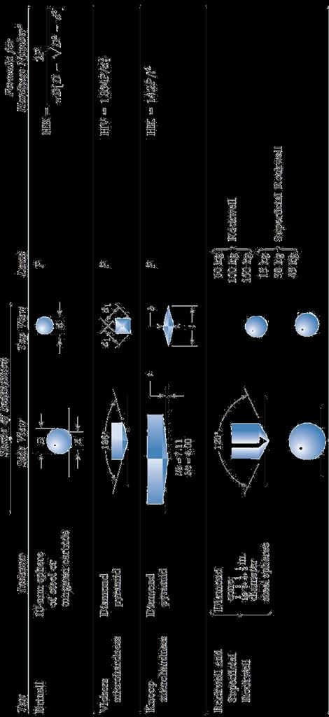
12 Hardness test methods: HARDNESS Hardness is defined as "Resistance of metal to plastic deformation, usually by indentation. However, the term may also refer to stiffness or temper or to resistance to scratching, abrasion, or cutting. The greater the hardness of the metal, the greater resistance it has to deformation. In metallurgy hardness is defined as the ability of a material to resist plastic deformation. This is the usual type of hardness test, in which a pointed or rounded indenter is pressed into a surface under a substantially static load. 2. HARDNESS MEASUREMENT Hardness measurement can be defined as macro-, micro- or nano- scale according to the forces applied and displacements obtained. Microhardness is the hardness of a material as determined by forcing an indenter such as a Vick-ers or Knoop indenter into the surface of the material under 15 to 1000 gf load; usually, the in-dentations are so small that they must be measured with a microscope. Micro-indenters works by pressing a tip into a sample and continuously measuring: applied load, penetration depth and cycle time. HARDNESS TESTS Hardness tests may be classified as (i) (ii) (iii) Scratch hardness test (Mohs hardness scale) Indentation test (Brinell, Rockwell and Vickers hardness tests) Rebound (Dynamic hardness) test (Shore scleroscope test) Most of the hardness tests are based on resistance to indentation. The indentation tests consists of forcing a indentor into the specimen and measuring the effects. Brinell Hardness Test Brinell hardness is determined by forcing a hard steel or carbide sphere of a specified diameter 12

13 under a specified load into the surface of a material and measuring the diameter of the indentation left after the test. The Brinell hardness number, or simply the Brinell number, is obtained by dividing the load used, in kilograms, by the actual surface area of the indentation, in square millimeters. The result is a pressure measurement, but the units are rarely stated. The Brinell hardness test uses a desk top machine to press a 10mm diameter, hardened steel ball into the surface of the test specimen. The machine applies a load of 500 kilograms for soft metals such as copper, brass and thin stock. A 1500 kilogram load is used for aluminum castings, and a 3000 kilogram load is used for materials such as iron and steel. The load is usually applied for 10 to 15 seconds. After the impression is made, a measurement of the diameter of the resulting round impression is taken. It is measured to plus or minus 0.05mm using a low-magnification portable microscope. The hardness is calculated by dividing the load by the area of the curved surface of the indention. The Brinell hardness test was one of the most widely used hardness tests during World War II. For measuring armour plate hardness the test is usually conducted by pressing a tungsten carbide sphere 10mm in diameter into the test surface for 10 seconds with a load of 3,000kg, then measuring the diameter of the resulting depression. The BHN is calculated according to the following formula: Figure: Brinell's hardness test method. 13
14 where BHN = the Brinell hardness number F = the imposed load in kg D = the diameter of the spherical indenter in mm Di = diameter of the resulting indenter impression in mm Several BHN tests are usually carried out over an area of armour plate. On a typical plate each test would result in a slightly different number. This is due not only to minor variations in quality of the armour plate (even homogenous armour is not absolutely uniform) but also because the test relies on careful measurement of the diameter of the depression. Small errors in this measurement will lead to small variations in BHN values. As a result, BHN is usually quoted as a range of values (e.g. 210 to 245, or ) rather than as a single value. Rockwell Hardness Test Rockwell hardness tests use different loads and penetrators (indentors) and depth of indentation is calibrated on a dial to a hardness number. To eliminate the effect of slackness and surface roughness, the indentor is loaded with minor load (10kg) and the major load (100kg for soft material and 140 kg for hard material) is applied. Depth of indentation due to major load is used as a measure of hardness. Hardened steel ball with 100 kg total load is used for B-scale; while diamond tipped cone of 120 o angle and 0.2 mm tip radius called Brale with 150 kg total load is used for c-scale. A minor load of 10 kg is first applied, which causes an initial penetration and holds the indenter in place. Then, the dial is set to zero and the major load is applied. Upon removal of the major load, the depth reading is taken while the minor load is still on. The hardness number may then be read directly from the scale. This test measures the difference in depth caused by two different forces, using a dial gauge. Using standard hardness conversion tables, the Rockwell hardness value is determined for the load applied, the diameter of the indentor, and the indentation depth. 14

15 Rockwell hardness number on B-scale, = And on C-scale = Where e = depth of indentation corresponding to major load. The Rockwell hardness tester to measure the hardness of metal measures resistance to penetration like the Brinell test, but in the Rockwell case, the depth of the impression is measured rather than the diametric area. With the Rockwell tester, the hardness is indicated directly on the scale attached to the machine. This dial like scale is really a depth gauge, graduated in special units. The Rockwell hardness test is the most used and versatile of the hardness tests. Vickers Hardness Test Figure: Rock-well hardness test method It is the standard method for measuring the hardness of metals, particularly those with extremely hard surfaces: the surface is subjected to a standard pressure for a standard length of time by means of a pyramid-shaped diamond. The diagonal of the resulting indention is measured under a microscope and the Vickers Hardness value read from a conversion table. Vickers hardness is a measure of the hardness of a material, calculated from the size of an impression produced under load by a pyramid-shaped diamond indenter. Devised in the 1920s by engineers at Vickers, Ltd., in the United Kingdom, the diamond pyramid hardness test, as it also became known, permitted the establishment of a continuous scale of comparable numbers that accurately reflected the wide range of hardnesses found in steels. 15
16 The indenter employed in the Vickers test is a square-based pyramid whose opposite sides meet at the apex at an angle of 136º. The diamond is pressed into the surface of the material at loads ranging up to approximately 120 kilograms-force, and the size of the impression (usually no more than 0.5 mm) is measured with the aid of a calibrated microscope. The Vickers number (HV) is calculated using the following formula: HV = with F being the applied load (measured in kilograms force) and the area of the indentation (measured in square millimetres). The applied load is usually specified when HV is cited. The Vickers machine uses a penetrator that is square in shape, but tipped on one corner so it has the appear ance of a playing card "diamond". The Vickers indenter is a 136 degrees square-based diamond cone, the diamond material of the indenter has an advantage over other indenters because it does not deform over time and use. The impression left by the Vickers penetrator is a dark square on a light background. The Vickers impression is more easily "read" for area size than the circular impression of the Brinell method. Like the Brinell test, the Vickers number is determined by dividing the load by the surface area of the indentation (H = P/A). The load varies from 1 to 120 kilo-grams. To perform the Vickers test, the specimen is placed on an anvil that has a screw threaded base. The anvil is turned raising it by the screw threads until it is close to the point of the inden - ter. With start lever activated, the load is slowly applied to the indenter. The load is released and the anvil with the specimen is lowered. The operation of applying and removing the load is con-trolled automatically. Vickers hardness test are that extremely accurate readings can be taken, and just one type of indenter is used for all types of metals and surface treatments. Although thoroughly adaptable and very precise for testing the softest and hardest of materials, under varying loads, the Vickers machine is a floor standing unit that is rather more expensive than the Brinell or Rockwell machines. 16

17 Figure: Vickers hardness test method. 17
18 18
19 Problems 1. A piece of copper originally 305 mm (12 in.) long is pulled in tension with a stress of 276 MPa (40,000 psi). If the deformation is entirely elastic, what will be the resultant elongation? 2. A specimen of copper having a rectangular cross section 15.2 mm X 19.1 mm (0.60 in.x 0.75in.) is pulled in tension with 44,500 N (10,000 lb ) force, producing only elastic deformation. Calculate the resulting strain. 3. A cylindrical specimen of nickel alloy having an elastic modulus of 207 Gpa and an original cross diameter of 10.2 mm will experience only elastic deformation when a tensile load of 8900 N is applied. Compute the maximum length of the specimen before deformation if the maximum allowable elongation is 0.25 mm. 4. A piece of copper originally 305 mm long is pulled in a tension with a stress of 276 M Pa. If the deformation is entirely elastic, what will be resultant elongation? Given 1 M Pa is 10 6 N/m A specimen of copper having a rectangular cross section 15.2 mm 19.1 mm (0.60 in.0.75 in.) is pulled in tension with 44,500 N (10,000 lb ) force, producing only elastic deformation. Calculate the resulting strain. 6. A cylindrical specimen of a nickel alloy having an elastic modulus of 207 GPa (psi) and an original diameter of 10.2 mm (0.40 in.) will experience only elastic deformation when a tensile load of 8900 N (2000 lb) is applied. Compute the maximum length of the specimen before deformation if the maximum allowable elongation is 0.25 mm (0.010 in.). 7. An aluminum bar 125 mm (5.0 in.) long and having a square cross section 16.5 mm (0.65 in) on an edge is pulled in tension with a load of 66,700 N (15,000 lb), and experiences an elongation of 0.43 mm (in.). Assuming that the deformation is entirely elastic, calculate the modulus of elasticity of the aluminum. 8. Consider a cylindrical nickel wire 2.0 mm (0.08 in.) in diameter and mm (1200 in.) long. Calculate its elongation when a load of300 N (67 lb) is applied. Assume that the deformations totally elastic. 9. For a brass alloy, the stress at which plastic deformation begins is 345 MPa (50,000 psi), and the modulus of elasticity is 103 GPa( 15X10 6 psi). (a) What is the maximum load that may be applied to a specimen with a cross-sectional area of 130 mm 2 (0.2 in 2 ) without plastic deformation? (b) If the original specimen length is 76 mm (3.0 in.), what is the maximum length to which it may be stretched without causing plastic deformation? 10. A cylindrical rod of steel ( E=207GPa, 30X10 6 psi) having a yield strength of 310 MPa (45,000 psi) is to be subjected to a load of 11,100 N (2500 lb ). If the length of the rod is 500 mm (20.0 in.), what must be the diameter to allow an elongation of 0.38 mm (0.015 in.)? 19
MECHANICAL PROPERTIES AND TESTS. Materials Science
 MECHANICAL PROPERTIES AND TESTS Materials Science Stress Stress is a measure of the intensity of the internal forces acting within a deformable body. Mathematically, it is a measure of the average force
Chapter Outline Mechanical Properties of Metals How do metals respond to external loads?
 Chapter Outline Mechanical Properties of Metals How do metals respond to external loads?! Stress and Strain " Tension " Compression " Shear " Torsion! Elastic deformation! Plastic Deformation " Yield Strength
11/2/2018 7:58 PM. Chapter 6. Mechanical Properties of Metals. Mohammad Suliman Abuhaiba, Ph.D., PE
 1 Chapter 6 Mechanical Properties of Metals 2 Assignment 7, 13, 18, 23, 30, 40, 45, 50, 54 4 th Exam Tuesday 22/11/2018 3 WHY STUDY Mechanical Properties of Metals? How various mechanical properties are
ME -215 ENGINEERING MATERIALS AND PROCESES
 ME -215 ENGINEERING MATERIALS AND PROCESES Instructor: Office: MEC325, Tel.: 973-642-7455 E-mail: samardzi@njit.edu PROPERTIES OF MATERIALS Chapter 3 Materials Properties STRUCTURE PERFORMANCE PROCESSING
Materials Engineering 272-C Fall 2001, Lectures 9 & 10. Introduction to Mechanical Properties of Metals
 Materials Engineering 272-C Fall 2001, Lectures 9 & 10 Introduction to Mechanical Properties of Metals From an applications standpoint, one of the most important topics within Materials Science & Engineering
Engineering Materials
 Engineering Materials Mechanical Properties of Engineering Materials Mechanical testing of engineering materials may be carried out for a number of reasons: The tests may simulate the service conditions
BFF1113 Engineering Materials DR. NOOR MAZNI ISMAIL FACULTY OF MANUFACTURING ENGINEERING
 BFF1113 Engineering Materials DR. NOOR MAZNI ISMAIL FACULTY OF MANUFACTURING ENGINEERING Course Guidelines: 1. Introduction to Engineering Materials 2. Bonding and Properties 3. Crystal Structures & Properties
High Temperature Materials. By Docent. N. Menad. Luleå University of Technology ( Sweden )
") of Materials Course KGP003 Ch. 6 High Temperature Materials By Docent. N. Menad Dept. of Chemical Engineering and Geosciences Div. Of process metallurgy Luleå University of Technology ( Sweden ) Mohs scale
of Materials Course KGP003 Ch. 6 High Temperature Materials By Docent. N. Menad Dept. of Chemical Engineering and Geosciences Div. Of process metallurgy Luleå University of Technology ( Sweden ) Mohs scale
CE 221: MECHANICS OF SOLIDS I CHAPTER 3: MECHANICAL PROPERTIES OF MATERIALS
 CE 221: MECHANICS OF SOLIDS I CHAPTER 3: MECHANICAL PROPERTIES OF MATERIALS By Dr. Krisada Chaiyasarn Department of Civil Engineering, Faculty of Engineering Thammasat university Outline Tension and compression
MECHANICAL PROPERTIES OF MATERIALS
 MECHANICAL PROPERTIES OF MATERIALS Stress-Strain Relationships Hardness Effect of Temperature on Properties Fluid Properties Viscoelastic Behavior of Polymers Mechanical Properties in Design and Manufacturing
THE MECHANICAL PROPERTIES OF STAINLESS STEEL
 THE MECHANICAL PROPERTIES OF STAINLESS STEEL Stainless steel is primarily utilised on account of its corrosion resistance. However, the scope of excellent mechanical properties the within the family of
Mechanical Properties of Metals. Goals of this unit
 Mechanical Properties of Metals Instructor: Joshua U. Otaigbe Iowa State University Goals of this unit Quick survey of important metal systems Detailed coverage of basic mechanical properties, especially
Welcome to ENR116 Engineering Materials. This lecture summary is part of module 2, Material Properties.
 Welcome to ENR116 Engineering Materials. This lecture summary is part of module 2, Material Properties. 1 2 Mechanical properties. 3 The intended learning outcomes from this lecture summary are that you
Properties of Engineering Materials
 Properties of Engineering Materials Syllabus Mechanical Properties, Tensile, Fatigue, Creep, Impact, Hardness, Chemical Properties, Physical properties, Corrosion and Cathodic Protection, Carbon Steel,
MECHANICAL PROPERTIES.
 MECHANICAL PROPERTIES. Hardness, strength, ductility and elasticity are among the mechanical properties of a material that would probably first come to mind. In order to know how each of these characteristics
Mechanical Characterisation of Materials
 Department of Materials and Metallurgical Engineering Bangladesh University of Engineering and Technology, Dhaka MME298 Structure and Properties of Biomaterials Sessional 1.50 Credits 3.00 Hours/Week July
Chapter 7: Mechanical Properties 1- Load 2- Deformation 3- Stress 4- Strain 5- Elastic behavior
 -1-2 -3-4 ( ) -5 ( ) -6-7 -8-9 -10-11 -12 ( ) Chapter 7: Mechanical Properties 1- Load 2- Deformation 3- Stress 4- Strain 5- Elastic behavior 6- Plastic behavior 7- Uniaxial tensile load 8- Bi-axial tensile
ME 207 Material Science I
 ME 207 Material Science I Chapter 5 Hardness and Hardness Testing Dr. İbrahim H. Yılmaz http://web.adanabtu.edu.tr/iyilmaz Automotive Engineering Adana Science and Technology University Introduction Hardness
MECHANICAL PROPERTIES
 MECHANICAL PROPERTIES Mechanical Properties: In the course of operation or use, all the articles and structures are subjected to the action of external forces, which create stresses that inevitably cause
MECHANICAL TESTING OF METALLIC MATERIALS
 MECHANICAL TESTING OF METALLIC MATERIALS Outline Hardness Testing Tensile Testing Impact Testing Fatigue Testing Creep Testing Wear Testing 22-Jan-11 11111 2 MATERIALS PROPERTIES Design Engineer - Materials
Chapter 4 MECHANICAL PROPERTIES OF MATERIAL. By: Ardiyansyah Syahrom
 Chapter 4 MECHANICAL PROPERTIES OF MATERIAL By: Ardiyansyah Syahrom Chapter 2 STRAIN Department of Applied Mechanics and Design Faculty of Mechanical Engineering Universiti Teknologi Malaysia 1 Expanding
Mechanical behavior of crystalline materials- Comprehensive Behaviour
 Mechanical behavior of crystalline materials- Comprehensive Behaviour In the previous lecture we have considered the behavior of engineering materials under uniaxial tensile loading. In this lecture we
AERO 214. Introduction to Aerospace Mechanics of Materials. Lecture 2
 AERO 214 Introduction to Aerospace Mechanics of Materials Lecture 2 Materials for Aerospace Structures Aluminum Titanium Composites: Ceramic Fiber-Reinforced Polymer Matrix Composites High Temperature
AML 883 Properties and selection of engineering materials
 AML 883 Properties and selection of engineering materials LECTURE 8. Plasticity M P Gururajan Email: guru.courses@gmail.com Room No. MS 207/A 3 Phone: 1340 Problem Sheet 3 Problems on strength limited
Reproducible evaluation of material properties. Static Testing Material response to constant loading
 Material Testing Material Testing Reproducible evaluation of material properties Static Testing Material response to constant loading Dynamic Testing Material response to varying loading conditions, including
Chapter 6: Mechanical Properties
 Chapter 6: Mechanical Properties ISSUES TO ADDRESS... Stress and strain: What are they and why are they used instead of load and deformation? Elastic behavior: When loads are small, how much deformation
CHAPTER 3 OUTLINE PROPERTIES OF MATERIALS PART 1
 CHAPTER 3 PROPERTIES OF MATERIALS PART 1 30 July 2007 1 OUTLINE 3.1 Mechanical Properties 3.1.1 Definition 3.1.2 Factors Affecting Mechanical Properties 3.1.3 Kinds of Mechanical Properties 3.1.4 Stress
FME201 Solid & Structural Mechanics I Dr.Hussein Jama Office 414
 FME201 Solid & Structural Mechanics I Dr.Hussein Jama Hussein.jama@uobi.ac.ke Office 414 Lecture: Mon 11am -1pm (CELT) Tutorial Tue 12-1pm (E207) 10/1/2013 1 CHAPTER OBJECTIVES Show relationship of stress
3. MECHANICAL PROPERTIES OF STRUCTURAL MATERIALS
 3. MECHANICAL PROPERTIES OF STRUCTURAL MATERIALS Igor Kokcharov 3.1 TENSION TEST The tension test is the most widely used mechanical test. Principal mechanical properties are obtained from the test. There
MECHANICAL PROPERTIES PROPLEM SHEET
 MECHANICAL PROPERTIES PROPLEM SHEET 1. A tensile test uses a test specimen that has a gage length of 50 mm and an area = 200 mm 2. During the test the specimen yields under a load of 98,000 N. The corresponding
Material Properties 3
 Material Properties 3 Real Stress and Strain True M Corrected Stress M Engineering Strain Several Alloys Material n MPa psi Low-carbon steel 0.26 530 77,000 (annealed) Alloy steel 0.15 640 93,000 (Type
The strength of a material depends on its ability to sustain a load without undue deformation or failure.
 TENSION TEST The strength of a material depends on its ability to sustain a load without undue deformation or failure. This strength is inherent in the material itself and must be determined by experiment.
REVISED PAGES IMPORTANT TERMS AND CONCEPTS REFERENCES QUESTIONS AND PROBLEMS. 166 Chapter 6 / Mechanical Properties of Metals
 1496T_c06_131-173 11/16/05 17:06 Page 166 166 Chapter 6 / Mechanical Properties of Metals IMPORTANT TERMS AND CONCEPTS Anelasticity Design stress Ductility Elastic deformation Elastic recovery Engineering
Reproducible evaluation of material properties. Static Testing Material response to constant loading
 Material Testing Material Testing Reproducible evaluation of material properties Static Testing Material response to constant loading Dynamic Testing Material response to varying loading conditions, including
بسم الله الرحمن الرحیم. Materials Science. Chapter 7 Mechanical Properties
 بسم الله الرحمن الرحیم Materials Science Chapter 7 Mechanical Properties 1 Mechanical Properties Can be characterized using some quantities: 1. Strength, resistance of materials to (elastic+plastic) deformation;
Chapter 6: Mechanical Properties
 Chapter 6: Mechanical Properties ISSUES TO ADDRESS... Stress and strain: What are they and why are they used instead of load and deformation? Elastic behavior: When loads are small, how much deformation
Chapter 8: Mechanical Properties of Metals. Elastic Deformation
 Chapter 8: Mechanical Properties of Metals ISSUES TO ADDRESS... Stress and strain: What are they and why are they used instead of load and deformation? Elastic behavior: When loads are small, how much
Mechanical Properties
 Stress-strain behavior of metals Elastic Deformation Plastic Deformation Ductility, Resilience and Toughness Hardness 108 Elastic Deformation bonds stretch δ return to initial Elastic means reversible!
Chapter 2: Mechanical Behavior of Materials
 Chapter : Mechanical Behavior of Materials Definition Mechanical behavior of a material relationship - its response (deformation) to an applied load or force Examples: strength, hardness, ductility, stiffness
Chapter 7. Mechanical properties 7.1. Introduction 7.2. Stress-strain concepts and behaviour 7.3. Mechanical behaviour of metals 7.4.
 Chapter 7. Mechanical properties 7.1. Introduction 7.2. Stress-strain concepts and behaviour 7.3. Mechanical behaviour of metals 7.4. Mechanical behaviour of ceramics 7.5. Mechanical behaviour of polymers
MECHANICAL PROPERTIES OF THIOUREA BASED ORGANIC AND SEMIORGANIC SINGLE CRYSTALS
 153 CHAPTER 7 MECHANICAL PROPERTIES OF THIOUREA BASED ORGANIC AND SEMIORGANIC SINGLE CRYSTALS 7.1 INTRODUCTION Hardness of a material is the resistance it offers to indentation by a much harder body. It
Chapter 7. Mechanical Properties
 Chapter 7 Mechanical Properties Chapter 7 Plastic Deformation, Ductility and Toughness Issues to address Stress and strain: What are they and why are they used instead of load and deformation? Elastic
Chapter 6: Mechanical Properties
 Chapter 6: Mechanical Properties ISSUES TO ADDRESS... Stress and strain: What are they and why are they used instead of load and deformation? Elastic behavior: When loads are small, how much deformation
True Stress and True Strain
 True Stress and True Strain For engineering stress ( ) and engineering strain ( ), the original (gauge) dimensions of specimen are employed. However, length and cross-sectional area change in plastic region.
Vickers Berkovich Knoop Conical Rockwell Spherical Figure 15 a variety of different indenter's shapes and sizes
 Hardness Test of Ceramic materials Hardness is a measure of a materials resistance to penetration by a hard indenter of defined geometry and loaded in prescribed manner, it is one of the most frequently
Mechanical behavior of crystalline materials - Stress Types and Tensile Behaviour
 Mechanical behavior of crystalline materials - Stress Types and Tensile Behaviour 3.1 Introduction Engineering materials are often found to posses good mechanical properties so then they are suitable for
Workshop Practice TA 102
 Workshop Practice TA 102 Lec 2 & 3 :Engineering Materials By Prof.A.Chandrashekhar Engineering Materials Materials play an important role in the construction and manufacturing of equipment/tools. Right
3. Mechanical Properties of Materials
 3. Mechanical Properties of Materials 3.1 Stress-Strain Relationships 3.2 Hardness 3.3 Effect of Temperature on Properties 3.4 Fluid Properties 3.5 Viscoelastic Properties Importance of Mechanical Properties
Chapter 6: Mechanical Properties: Part One
 Slide 1 Chapter 6: Mechanical Properties: Part One ` 6-1 Slide 2 Learning Objectives 1. Technological significance 2. Terminology for mechanical properties 3. The tensile test: Use of the stress strain
When an axial load is applied to a bar, normal stresses are produced on a cross section perpendicular to the axis of the bar.
 11.1 AXIAL STRAIN When an axial load is applied to a bar, normal stresses are produced on a cross section perpendicular to the axis of the bar. In addition, the bar increases in length, as shown: 11.1
Metals are generally ductile because the structure consists of close-packed layers of
 Chapter 10 Why are metals ductile and ceramics brittle? Metals are generally ductile because the structure consists of close-packed layers of atoms that allow for low energy dislocation movement. Slip
Dharmapuri LAB MANUAL. Regulation : 2013 Branch. : B.E. Civil Engineering CE6411 STRENGTH OF MATERIALS LABORATORY
 Dharmapuri 636 703 LAB MANUAL Regulation : 2013 Branch Year & Semester : B.E. Civil Engineering : II Year / IV Semester CE6411 STRENGTH OF MATERIALS LABORATORY OBJECTIVE: ANNA UNIVERSITY CE-6411 STRENGTH
NDT Deflection Measurement Devices: Benkelman Beam (BB) Sri Atmaja P. Rosyidi, Ph.D., P.E. Associate Professor
 Sri Atmaja P. Rosyidi, Ph.D., P.E. Associate Professor") NDT Deflection Measurement Devices: Benkelman Beam (BB) Sri Atmaja P. Rosyidi, Ph.D., P.E. Associate Professor NDT Deflection Measurement Devices on Pavement Structure NDT measurement of pavement surface
NDT Deflection Measurement Devices: Benkelman Beam (BB) Sri Atmaja P. Rosyidi, Ph.D., P.E. Associate Professor NDT Deflection Measurement Devices on Pavement Structure NDT measurement of pavement surface
The Mechanical Properties of Polymers
 The Mechanical Properties of Polymers Date: 14/07/2018 Abu Zafar Al Munsur Behavior Of Material Under Mechanical Loads = Mechanical Properties. Term to address here Stress and strain: These are size-independent
MATERIALS: Clarifications and More on Stress Strain Curves
 A 3.0 m length of steel rod is going to be used in the construction of a bridge. The tension in the rod will be 10 kn and the rod must extend by no more than 1.0mm. Calculate the minimum cross-sectional
CHAPTER 4 1/1/2016. Mechanical Properties of Metals - I. Processing of Metals - Casting. Hot Rolling of Steel. Casting (Cont..)
") Processing of Metals - Casting CHAPTER 4 Mechanical Properties of Metals - I Most metals are first melted in a furnace. Alloying is done if required. Large ingots are then cast. Sheets and plates are then
Processing of Metals - Casting CHAPTER 4 Mechanical Properties of Metals - I Most metals are first melted in a furnace. Alloying is done if required. Large ingots are then cast. Sheets and plates are then
Tensile/Tension Test Fundamentals
 CIVE.3110 Engineering Materials Laboratory Fall 2016 Tensile/Tension Test Fundamentals Tzuyang Yu Associate Professor, Ph.D. Structural Engineering Research Group (SERG) Department of Civil and Environmental
Quiz 1 - Mechanical Properties and Testing Chapters 6 and 8 Callister
 Quiz 1 - Mechanical Properties and Testing Chapters 6 and 8 Callister You need to be able to: Name the properties determined in a tensile test including UTS,.2% offset yield strength, Elastic Modulus,
CITY AND GUILDS 9210 Unit 130 MECHANICS OF MACHINES AND STRENGTH OF MATERIALS OUTCOME 1 TUTORIAL 1 - BASIC STRESS AND STRAIN
 CITY AND GUILDS 910 Unit 130 MECHANICS O MACHINES AND STRENGTH O MATERIALS OUTCOME 1 TUTORIAL 1 - BASIC STRESS AND STRAIN Outcome 1 Explain static equilibrium, Newton's laws, and calculation of reaction
YIELD & TENSILE STRENGTH OF STEEL & ALUMINIUM USING MICROINDENTATION
 YIELD & TENSILE STRENGTH OF STEEL & ALUMINIUM USING MICROINDENTATION Prepared by Duanjie Li, PhD & Pierre Leroux 6 Morgan, Ste156, Irvine CA 9618 P: 949.461.99 F: 949.461.93 nanovea.com Today's standard
CHAPTER 6: MECHANICAL PROPERTIES ISSUES TO ADDRESS...
 CHAPTER 6: MECHANICAL PROPERTIES ISSUES TO ADDRESS... Stress and strain: What are they and why are they used instead of load and deformation? Elastic behavior: When loads are small, how much deformation
When an axial load is applied to a bar, normal stresses are produced on a cross section perpendicular to the axis of the bar.
 11.1 AXIAL STRAIN When an axial load is applied to a bar, normal stresses are produced on a cross section perpendicular to the axis of the bar. In addition, the bar increases in length, as shown: 11.1
MECHANICS OF MATERIALS. Mechanical Properties of Materials
 MECHANICS OF MATERIALS Mechanical Properties of Materials By NUR FARHAYU ARIFFIN Faculty of Civil Engineering & Earth Resources Chapter Description Expected Outcomes Understand the concept of tension and
ME 212 EXPERIMENT SHEET #2 TENSILE TESTING OF MATERIALS
 ME 212 EXPERIMENT SHEET #2 TENSILE TESTING OF MATERIALS 1. INTRODUCTION & THEORY The tension test is the most commonly used method to evaluate the mechanical properties of metals. Its main objective is
Chapter 6: Mechanical Properties
 ISSUES TO ADDRESS... Stress and strain Elastic behavior: When loads are small, how much reversible deformation occurs? What material resist reversible deformation better? Plastic behavior: At what point
MECHANICAL PROPERTIES. (for metals)
") MECHANICAL PROPERTIES (for metals) 1 Chapter Outline Terminology for Mechanical Properties The Tensile Test: Stress-Strain Diagram Properties Obtained from a Tensile Test True Stress and True Strain The
MECHANICAL PROPERTIES (for metals) 1 Chapter Outline Terminology for Mechanical Properties The Tensile Test: Stress-Strain Diagram Properties Obtained from a Tensile Test True Stress and True Strain The
CHAPTER 3 - MECHANICAL PROPERTIES. Mechanical properties are the characteristic responses of a material to applied stresses. Selection of mechanical
 CHAPTER 3 - MECHANICAL PROPERTIES Mechanical properties are the characteristic responses of a material to applied stresses. Selection of mechanical tests for a particular application is based primarily
MECHANICAL PROPERTIES OF MATERIALS. Manufacturing materials, IE251 Dr M. Eissa
 MECHANICAL PROPERTIES OF MATERIALS, IE251 Dr M. Eissa MECHANICAL PROPERTIES OF MATERIALS 1. Bending Test (Slide 3) 2. Shear Test (Slide 8) 3. Hardness (Slide 14) 4. Effect of Temperature on Properties
Question Paper Code : 11410
 Reg. No. : Question Paper Code : 11410 B.E./B.Tech. DEGREE EXAMINATION, APRIL/MAY 2011 Fourth Semester Mechanical Engineering ME 2254 STRENGTH OF MATERIALS (Common to Automobile Engineering and Production
STRENGTH OF MATERIALS laboratory manual
 STRENGTH OF MATERIALS laboratory manual By Prof. Shaikh Ibrahim Ismail M.H. Saboo Siddik College of Engineering, MUMBAI TABLE OF CONTENT Sr. No. Title of Experiment page no. 1. Study of Universal Testing
Concepts of stress and strain
 Chapter 6: Mechanical properties of metals Outline Introduction Concepts of stress and strain Elastic deformation Stress-strain behavior Elastic properties of materials Plastic deformation Yield and yield
Page 1 of 46 Exam 1. Exam 1 Past Exam Problems without Solutions NAME: Given Formulae: Law of Cosines: C. Law of Sines:
 NAME: EXAM 1 PAST PROBLEMS WITHOUT SOLUTIONS 100 points Tuesday, September 26, 2017, 7pm to 9:30 You are allowed to use a calculator and drawing equipment, only. Formulae provided 2.5 hour time limit This
Chapter 6:Mechanical Properties
 Chapter 6:Mechanical Properties Why mechanical properties? Need to design materials that can withstand applied load e.g. materials used in building bridges that can hold up automobiles, pedestrians materials
NANOINDENTATION CREEP MEASUREMENT
 NANOINDENTATION CREEP MEASUREMENT Prepared by Jorge Ramirez 6 Morgan, Ste156, Irvine CA 9618 P: 949.461.99 F: 949.461.93 nanovea.com Today's standard for tomorrow's materials. 010 NANOVEA INTRO Creep can
CE205 MATERIALS SCIENCE PART_6 MECHANICAL PROPERTIES
 CE205 MATERIALS SCIENCE PART_6 MECHANICAL PROPERTIES Dr. Mert Yücel YARDIMCI Istanbul Okan University Deparment of Civil Engineering Chapter Outline Terminology for Mechanical Properties The Tensile Test:
Engineering Materials
 Engineering Materials PREPARED BY Academic Services August 2011 Institute of Applied Technology, 2011 Module Objectives After the completion of this module, the student will be able to: Explain the terms
Correlation of Hardness Values to Tensile Strength
 Correlation of Hardness Values to Tensile Strength Semih Genculu, P.E. Various procedures and approaches are utilized to determine if a given material is suitable for a certain application. The material
Types of Strain. Engineering Strain: e = l l o. Shear Strain: γ = a b
 Types of Strain l a g Engineering Strain: l o l o l b e = l l o l o (a) (b) (c) Shear Strain: FIGURE 2.1 Types of strain. (a) Tensile. (b) Compressive. (c) Shear. All deformation processes in manufacturing
ENGINEERING MATERIAL 100
 Department of Applied Chemistry Division of Science and Engineering SCHOOL OF ENGINEERING ENGINEERING MATERIAL 100 Experiments 4 and 6 Mechanical Testing and Applications of Non-Metals Name: Yasmin Ousam
Tutorial 2 : Crystalline Solid, Solidification, Crystal Defect and Diffusion
 Tutorial 1 : Introduction and Atomic Bonding 1. Explain the difference between ionic and metallic bonding between atoms in engineering materials. 2. Show that the atomic packing factor for Face Centred
FACULTY OF ENGINEERING UNIVERSITY OF MAURITIUS. Mechanical properties of Materials UTOSP 1293 Basics of Metallurgy Prepared by s.
 FACULTY OF ENGINEERING UNIVERSITY OF MAURITIUS Mechanical properties of Materials UTOSP 1293 Basics of Metallurgy Prepared by s. Venkannah MECHANICAL PROPERTIES Engineers are basically concerned with the
Chapter 6 Mechanical Properties
 Engineering Materials MECH 390 Tutorial 2 Chapter 6 Mechanical Properties Chapter 3-1 6.14:A cylindrical specimen of steel having a diameter of 15.2 mm and length of 250 mm is deformed elastically in tension
Tensile Testing. Objectives
 Laboratory 3 Tensile Testing Objectives Students are required to understand the principle of a uniaxial tensile testing and gain their practices on operating the tensile testing machine to achieve the
Nano Puncture Resistance Using Nanoindentation
 Nano Puncture Resistance Using Nanoindentation Prepared by Jorge Ramirez 6 Morgan, Ste156, Irvine CA 9618 P: 949.461.99 F: 949.461.93 nanovea.com Today's standard for tomorrow's materials. 011 NANOVEA
EXPERIMENT NO.1 AIM: - OBJECT: - To determined tensile test on a metal. APPRETERS:- THEORY:-
 EXPERIMENT NO.1 AIM: - OBJECT: - APPRETERS:- DIAGRAM:- THEORY:- To determined tensile test on a metal. To conduct a tensile test on a mild steel specimen and determine the following: (i) Limit of proportionality
Chapter 6: Mechanical Properties
 Chapter 6: Mechanical Properties Elastic behavior: When loads are small, how much deformation occurs? What materials deform least? Stress and strain: What are they and why are they used instead of load
Part IA Paper 2: Structures and Materials MATERIALS Examples Paper 3 Stiffness-limited Design; Plastic Deformation and Properties
 Engineering Part IA Paper 2: Structures and Materials MATERIALS FIRST YEAR Examples Paper 3 Stiffness-limited Design; Plastic Deformation and Properties Straightforward questions are marked with a Tripos
CHAPTER 6: Mechanical properties
 CHAPTER 6: Mechanical properties ISSUES TO ADDRESS... Stress and strain: What are they and why are they used instead of load and deformation? Elastic behavior: When loads are small, how much deformation
Plastic stress-strain behaviour of metals Energy of mechanical ldeformation Hardness testing Design/safety factors
 Mechanical Properties of Materials 2 Prof. A.K.M.B. Rashid Department of MME BUET, Dhaka Plastic stress-strain behaviour of metals Energy of mechanical ldeformation Hardness testing Design/safety factors
HONEYCOMB MECHANICAL BEHAVIOR USING MACROINDENTATION
 HONEYCOMB MECHANICAL BEHAVIOR USING MACROINDENTATION. Prepared by Duanjie Li, PhD 6 Morgan, Ste156, Irvine CA 92618 P: 949.461.9292 F: 949.461.9232 nanovea.com Today's standard for tomorrow's materials.
Properties in Shear. Figure 7c. Figure 7b. Figure 7a
 Properties in Shear Shear stress plays important role in failure of ductile materials as they resist to normal stress by undergoing large plastic deformations, but actually fail by rupturing under shear
P A (1.1) load or stress. elongation or strain
 load or stress. elongation or strain") load or stress MEEN 3145 TENSION TEST - BACKGROUND The tension test is the most important and commonly used test in characterizing properties of engineering materials. This test gives information essential
load or stress MEEN 3145 TENSION TEST - BACKGROUND The tension test is the most important and commonly used test in characterizing properties of engineering materials. This test gives information essential
ME 215 Engineering Materials I
 ME 215 Engineering Materials I Chapter 5 Hardness and Hardness Testing (Part II) Mechanical Engineering University of Gaziantep Dr. A. Tolga Bozdana www.gantep.edu.tr/~bozdana Shore Scleroscope Test Invented
Materials Properties 2
 Materials Properties 2 Elastic Deformation Most metals can only obey hook s law for s up to 0.005 Elastic Plastic y P Nearly all engineering is performed in the elastic region 0.002 Elastic Plastic y P
Deformation, plastic instability
 Deformation, plastic instability and yield-limited design Engineering Materials 2189101 Department of Metallurgical Engineering Chulalongkorn University http://pioneer.netserv.chula.ac.th/~pchedtha/ Material
CHAPTER 8 DEFORMATION AND STRENGTHENING MECHANISMS PROBLEM SOLUTIONS
 CHAPTER 8 DEFORMATION AND STRENGTHENING MECHANISMS PROBLEM SOLUTIONS Slip Systems 8.3 (a) Compare planar densities (Section 3.15 and Problem W3.46 [which appears on the book s Web site]) for the (100),
EDGE CHIPPING RESISTANCE USING MACROINDENTATION TESTING
 EDGE CHIPPING RESISTANCE USING MACROINDENTATION TESTING Prepared by Ali Mansouri 6 Morgan, Ste156, Irvine CA 92618 P: 949.461.9292 F: 949.461.9232 nanovea.com Today's standard for tomorrow's materials.
MATERIALS SCIENCE-44 Which point on the stress-strain curve shown gives the ultimate stress?
 MATERIALS SCIENCE 43 Which of the following statements is FALSE? (A) The surface energy of a liquid tends toward a minimum. (B) The surface energy is the work required to create a unit area of additional
Lab Exercise #2: Tension Testing (Uniaxial Stress)
") Lab Exercise #2: (Uniaxial Stress) Learning Outcomes: 1. Understand the basic concepts of stress and strain 2. Identify the engineering material properties 3. Connect stress and strain through Hooke s
Lab Exercise #2: (Uniaxial Stress) Learning Outcomes: 1. Understand the basic concepts of stress and strain 2. Identify the engineering material properties 3. Connect stress and strain through Hooke s
5. A round rod is subjected to an axial force of 10 kn. The diameter of the rod is 1 inch. The engineering stress is (a) MPa (b) 3.
 MPa (b) 3.") The Avogadro's number = 6.02 10 23 1 lb = 4.45 N 1 nm = 10 Å = 10-9 m SE104 Structural Materials Sample Midterm Exam Multiple choice problems (2.5 points each) For each problem, choose one and only one
The Avogadro's number = 6.02 10 23 1 lb = 4.45 N 1 nm = 10 Å = 10-9 m SE104 Structural Materials Sample Midterm Exam Multiple choice problems (2.5 points each) For each problem, choose one and only one