AP 5301/8301 Instrumental Methods of Analysis and Laboratory Lecture 5 X ray diffraction
|
|
|
- Jordan Thompson
- 6 years ago
- Views:
Transcription
1 1 AP 5301/8301 Instrumental Methods of Analysis and Laboratory Lecture 5 X ray diffraction Prof YU Kin Man kinmanyu@cityu.edu.hk Tel: Office: P6422
2 Lecture 5: Outline Review on crystallography Lattice and crystal structure Miller indices Diffraction Braggs law Reciprocal lattice X-ray diffraction X-ray source and characteristic x-ray Diffraction intensity structure factor Powder diffraction analysis Phase identification Grain size and strain Texture Rocking curve Advanced XRD techniques Grazing incident High resolution Other advanced x-ray techniques 2
3 Review: crystal lattice 3 An infinite array of points in space. Each point has identical surroundings to all others. Arrays are arranged exactly in a periodic manner. y B b O α C a A x D E A crystal lattice is a set of infinite, arranged points related to each other by transitional symmetry.

: r = r + u 1 a 1 + u 2 a 2 u 1, u 2 are integers a 2 a 1 a 2 b 2 r 4 a 1 a n, a n are primitive translation vectors (defined a minimum area) while b n are not b 1 3 dimension (3D): r")
4 Review: lattices & lattice translation vectors Lattice translation vectors a 1, a 2 describe how to move around a crystal A translation by any combination of the vectors will lead to another equivalent point and leaves the lattice unchanged translation symmetry a 1, a 2 are the basis vectors and the choice of the basis vector is not unique. Equivalent points have the same environment in the same orientation. 2 dimension (2D): r = r + u 1 a 1 + u 2 a 2 u 1, u 2 are integers a 2 a 1 a 2 b 2 r 4 a 1 a n, a n are primitive translation vectors (defined a minimum area) while b n are not b 1 3 dimension (3D): r r = r + u 1 a 1 + u 2 a 2 + u 3 a 3 For n dimensions: r =r+ n u n a n a 3 r a 2 a 1 or r = r + u 1 a + u 2 b + u 3 c Lattice translation vectors a n are primitive if there is no other cell of volume < a 1 a 2 a 3 that can build the lattice

5 Review: Bravais Lattice 5 In 1850, Auguste Bravais showed that there are only 14 different ways of arranging identical points in 3D space so that the points are equivalent in their surroundings. These arrangement are later called the Bravais Lattices. A Bravais Lattice is defined as an infinite array of points which appears exactly the same when viewed from any one of the lattice points. A Bravais Lattice consists of all points with position vector r of the form r = u 1 a+ u 2 b + u 3 c where a, b, c are any three non-coplanar primitive translation vectors and u i range through all integer values. There are only 7 different shapes of unit cell which can be stacked together to completely fill a 3 dimensional space without overlapping. This gives the 7 crystal systems with 14 Bravais lattices in which all crystal structure can be classified. The systems are defined according to the relationship between the 6 lattice constants: a, b, c, ( or a 1, a 2 a 3 )a, b, and g.
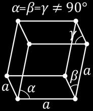
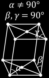
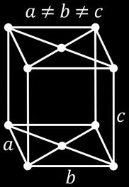
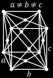
6 Crystal systems and Bravais lattices 6 Crystal System Conventional Unit Cell Bravais Lattices Triclinic Monoclinic Orthorhombic Tetragonal Cubic Trigonal/ Rhombohedral Hexagonal a b c α β γ a b c α = β = 90º γ a b c α = β = γ = 90º a = b c α = β = γ = 90º a = b = c α = β = γ a = b = c 120º > α = β = γ 90º a = b c α = β = 90º, γ = 60º Primitive (P) Primitive, Base-centered (C) Primitive, Base-centered, Bodycentered (I), Face-centered (F) Primitive, Body-centered Primitive, Body-centered, Facecentered Primitive Primitive


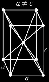
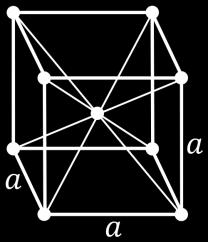
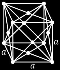
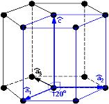
7 14 Bravais lattices 7 Triclinic Monoclinic Cubic Trigonal/ rhombodedral Orthorhombic Tetragonal Hexagonal P Simple/Primitive I Body Centered F Face Centered C Base Centered
8 Crystal structure=lattice+basis 8 Each lattice point can be an atom, group of atoms and molecules in the crystal basis. In a real crystal the lattice point is replaced by a basis and every basis is identical in composition, arrangement and orientation b a + 2 D lattice basis crystal r j If r j for the element B is 0, position of element A r j = x j a + y j b In 3D: r j = x j a + y j b + z j c where 0 x j, y j, z j 1

9 Crystal Structure 9 The atoms do not necessarily lie at lattice points but basis must be in the same orientation 3D + lattice basis Crystal structure


10 Crystal planes: 3-D 10 In a 3D crystal lattice we can identify multiple sets of equally spaced parallel planes Each group of planes forms a set and are a property of the lattice How do we define the planes?
11 Miller indices for planes 11 Miller Indices are a symbolic vector representation for the orientation of an atomic plane in a crystal lattice and are defined as the reciprocals of the fractional intercepts which the plane makes with the crystallographic axes. Method If the plane passes through the origin, select an equivalent plane or move the origin. Determine the intercepts of the plane along each of the three crystallographic directions. Take the reciprocals of the intercepts (if the plane does not intersect one of the axes, the intercept is at infinity and the inverse is zero). (1, 0, 0) Miller Indices (1 1 1) Enclose in parentheses ( ) X Y Z Intercepts 1 1 1/2 Reciprocals x z (0, 0, 1/2) (0, 1,0) y
12 Family of planes In some situation when the unit cell has rotational symmetry, nonparallel planes may be equivalent by virtue of this symmetry. These plane are grouped together and called a family of planes and is expressed by a curly bracket {hkl} Examples in a cubic system: 100 : 100, 010, 001, 100, 0 10, : 111, 11 1, 1 11, 111, 1 1 1, 1 11, 11 1, (0 1 0) y x z z 12 (010) y (111) (111) y Two successive planes of indices (hkl) make intercepts na/h, nb/k, nc/l and (n+1)a/h, (n+1)b/k, (n+1)c/l, respectively, where n is an integer. The perpendicular distance between successive planes, or interplanar spacing d hkl, can be shown to be given by d hkl = 1 h A+kB+l C, h A + kb + l C 2 = h A + kb + l C h A + kb + l C x For an orthorhombic crystal: α = β = γ = 90 o ; A = 1, B = 1, C = 1 a b c 1 2 = h2 d hkl a 2 + k2 b 2 + l2 c 2
13 13 Plane separation d hkl Crystal System Unit Cell Characteristics d hkl Cubic Tetragonal Orthorhombic Hexagonal Monoclinic Trigonal/ Rhombohedral a = b = c 1 α = β = γ = 90 o d 2 = h2 + k 2 + l 2 a 2 a = b c 1 α = β = γ = 90 o d 2 = h2 + k 2 a 2 + l2 c 2 a b c α = β = γ = 90 o 1 d 2 = h2 a 2 + k2 b 2 + l2 c 2 a = b c 1 α = β = 90 o, γ = 60 o d 2 = 4 3 a b c α = β = 90º γ a = b = c 120 o > α = β = γ 90 o 1 d 2 = 1 sin 2 β h 2 + hk + k 2 a 2 + l2 c 2 h 2 a 2 + k2 sin 2 β b 2 + l2 c 2 2hlcosβ ac 1 d 2 = h2 + k 2 + l 2 sin 2 α + 2 hk + kl + hl cos 2 α cosα a 2 1 3cos 2 α + 2cos 3 α


14 Review: diffraction Diffraction is a wave phenomenon in which the apparent bending and spreading of waves occur when they meet an obstacle. Diffraction occurs with all waves including electromagnetic waves, such as light and radio waves as well as sound waves, water waves and matter waves. The simplest demonstration of diffraction is the double-slit diffraction experiment. 14 Interference pattern (fringes) Wider separation between the fringes with narrower slit separation.
15 Diffraction from a particle and solid 15 Single Particle The particle scatters the incident beam in all directions. Solid (a matrix of particles) For a crystalline solid, the scattered beams may add in a few directions to produce unique pattern. scattered f e r i( k r t) f = atomic form factor (scattering power of atom) =amplitude

16 Electromagnetic spectrum 16 X-rays are well suited to probe crystal structure
 Max von Laue (1879-1960) Sir William Lawrence Bragg, FRS")

 Typical X-ray wavelength ~ 0.")

17 X-ray crystallography: a short history 17 Sir William Henry Bragg, FRS ( ) Wilhelm Röntgen ( ) Max von Laue ( ) Sir William Lawrence Bragg, FRS ( ) 1895: Röntgen discovered X-rays and led to the development of the field of X-ray diffraction crystallography (Röntgen was the first recipient of the Nobel prize in physics, in 1901) Max von Laue developed the use of X- ray diffraction (Nobel Prize, 1914) Typical X-ray wavelength ~ 0.1nm which is similar to interatomic spacing in crystals :The Braggs together developed the principles for the analysis of crystal structure by means of X-rays and shared the 1915 Nobel Prize in physics
18 Diffraction When a wave incident on a crystal (periodic arrays of atoms) 18 a a a When l<2a: wave either passes through crystal (k unchanged) or for a particular incident angle will be diffracted

19 Bragg s law 19 When a monochromatic x-ray beam is incident on the surface of a crystal, the reflection takes places only when the angle of incidence has certain values. Bragg considered crystals as a set of parallel planes of atoms. The incident beam is reflected partially at each of these planes. The reflected rays are collected by a detector at a distance. According to physical optics, the interference is constructive only if the difference between the paths of any two consecutive rays is an integral multiple of the wavelength. The path difference D D nl n 1,2,3,..integers 2d sin θ = nλ
20 Bragg s law d 1 q 1 q 1 q 2 d 2 sin θ1 n 1 l d 2 sin θ2 n 2 Note: The smaller the spacing d, the higher the angle of reflection q. l The incident beam, the normal to the reflection plane, and the diffracted beam are always coplanar. The angle between the diffracted beam and the transmitted beam is always 2q (usually measured). sin θ cannot be more than unity; this requires nλ < 2d, for n = 1, λ < 2d This is why we cannot use visible light. 20 The diffracted beams from any set of lattice planes can only occur at the angles predicted by the Bragg law. The set of lattice planes is then represented by the diffracted beam, or diffracted spots.

21 The reciprocal lattice 21 Bragg s Law shows that there is a reciprocal relationship between the plane spacing d and the diffraction angle q, we can therefore relate the diffraction pattern to the crystal lattice by a mathematical construct, the reciprocal lattice. The reciprocal lattice is a set of imaginary points in which the direction of a vector from one point to another corresponds to a direction normal to a plane in a real lattice We can view the pattern created from X- ray diffraction as a new lattice that we can use to gain information about the crystal lattice. d = nλ 2 sin θ X-ray diffraction pattern for a single alum crystal - wiki.brown.edu
22 The Reciprocal Lattice Crystal planes (hkl) in the real-space or direct lattice are characterized by the normal vector n hkl and the interplanar spacing d hkl. x z nˆhkl d hkl y 22 In the reciprocal lattice, the position of the lattice point in the reciprocal space is given by the vector This vector is parallel to the [hkl] 2 G direction but has magnitude 2/d hkl, hkl nˆ hkl dhkl which is a reciprocal distance The reciprocal lattice is composed of all points lying at positions G hkl from the origin, so that there is one point in the reciprocal lattice for each set of planes (hkl) in the real-space lattice. So why do we need the reciprocal lattice? The reciprocal lattice simplifies the interpretation of diffraction data from crystals. The reciprocal lattice facilitates the calculation of wave propagation in the crystal (lattice vibrations, electron waves, etc.)
23 2D Reciprocal Lattice 23 Direct (Real) Space Reciprocal Space n 01 d 11 d 01 n 11 n 10 (01) planes (01) 2π d 01 o 2π (10) (11) d 10 d 10 pick some point as an origin lay out the normal to every family of parallel planes in the direct lattice set the length of each normal equal to 2X the reciprocal of the interplanar spacing ( 2π ) for its particular set of planes d place a point at the end of each normal
24 3D Reciprocal Lattice Reciprocal lattice vector can be written as The reciprocal lattice base vectors are defined: There are simple dot product relationships between reciprocal and directspace lattice vectors: Here, c b a c b A 2 c b a a c B 2 c b a b a C 2 2 c C b B a A b C a C a B c B c A b A 0 π l c G k b G h a G hkl hkl hkl 2 ; 2 ; 2 Reciprocal lattice direct lattice G = XA + YB + Z C Area of a plane in the unit cell in the direction plane Volume of real unit cell 24
25 The Laue Condition 25 For constructive interference, the scattering vector S must be a reciprocal lattice vector. S 2 k sin θ B Shkl G hkl We also know that: G hkl = 2π d hkl k 0 k Laue Equations: 2 2π λ sin θ hkl = 2π d hkl S a = 2πh S b = 2πk S c = 2πl Shkl G hkl q B k k 0 k 0 S=k-k 0 2 l Elastic Scattering λ = 2d hkl sin θ hkl Bragg s Law S hkl = 2 2π λ sin θ hkl


26 X-ray diffraction (XRD) 26 The lattice structure determines the position of the lines. The basis determines the relative intensity.
 between the cathode (W) and the anode, which is a water-cooled block of Cu or Mo containing desired target metal.")
27 X-ray source 27 A typical Coolidge tube X-rays are produced whenever high-speed electrons collide with a metal target. A source of electrons hot W filament, a high accelerating voltage (30-50kV) between the cathode (W) and the anode, which is a water-cooled block of Cu or Mo containing desired target metal. The x-ray output is the shape characteristic x-ray lines of the anode metal on a continuum of bremsstrahlung radiation


28 X-ray production 28 As some e - approach the nucleus and are slowed down and pulled into a new direction, consequently some energy is released in the form of X-rays called Bremsstrahlung.


29 X-ray source: characteristic x-rays 29 Characteristic x-ray line energy= E final E initial Relative intensities of major x-ray lines K α1 = 100 L α1 = 100 M α1,2 = 100 K α2 = 50 L α2 = 50 M β = 60 K β1 = L β1 = 50 K β2 = 1 10 L β2 = 250 K β3 = 6 15 L β3 = 1 6 L β4 = 3 5 L γ1 = 1 10 If an incoming electron has sufficient kinetic energy for knocking out an electron of the K shell (the inner-most shell), it may excite the atom to an high-energy state (K state). One of the outer electron falls into the K- shell vacancy, emitting the excess energy as a x-ray photon. Characteristic x-ray energy: E x ray = E final E initial
30 Characteristic x-ray and filters 30 Element K a1 (Å) K a2 (Å) K b (Å) K absorption edge (Å) Ag Mo Cu Ni Co Excitation potential (kv) Accurate XRD measurements requires a single x-ray line as the probe. For example, for a Cu anode, Kb line can be eliminated by a Ni filter
31 Diffraction intensity Diffraction intensity: I hkl F hkl 2 F hkl - Structure Factor 31 F hkl = basis f j exp 2πi(hu j + kv j + lw j ) where f j is the atomic scattering factor, and is dependent on atomic number u j,v j, w j are the fractional distances within the unit cell h, k, l is the Miller indices of the plane Atomic scattering factor: λ f θ sin θ Z 2 where Z is the atomic number of the atom Ag Br Fe Denser atoms scatter with greater intensity Intensity decreases as the scattering angle increases C
 + exp 2πi h 2 + k 2 = f 1 + e iπ(h+l) + e iπ(h+k) + e iπ(k+l) + exp 2πi k 2 + l 2 F hkl = 4f h, h, l all odd or all even 0 h, k, l mixed e.g. (111), (220), (222), etc.")
32 Structure factor: FCC crystal 32 D Four atoms at positions, (uvw): A(0,0,0), B(½,0,½), C(½,½,0), D(0,½,½) F hkl = basis f j exp 2πi(hu j + kv j + lw j ) F hkl = f = f exp 2πi 0 + exp 2πi basis h 2 + l 2 exp 2πi(hu j + kv j + lw j ) + exp 2πi h 2 + k 2 = f 1 + e iπ(h+l) + e iπ(h+k) + e iπ(k+l) + exp 2πi k 2 + l 2 F hkl = 4f h, h, l all odd or all even 0 h, k, l mixed e.g. (111), (220), (222), etc. (210), (112), (320), etc.
33 Structure factor 33 BCC Al For monatomic BCC crystals: F hkl = 2f if h + k + l is even 0 if h + k + l is odd For FCC crystals: F hkl = 4f h, h, l all odd or all even 0 h, k, l mixed


 are used instead of the film to record both")
34 X-ray powder diffraction 34 X-ray powder diffraction (XRD) is a rapid analytical technique primarily used for phase identification of a crystalline material and can provide information on unit cell dimensions. Samples can be powder, sintered pellets, thin film coatings on substrates, etc. The sample holder and the x-ray detector are mechanically linked. If the sample holder turns q, the detector turns 2q, so that the detector is always ready to detect the Bragg diffracted beam. x-ray detectors (e.g. Geiger counters) are used instead of the film to record both the position and intensity of the x-ray peaks Bragg-Brentano geometry
35 XRD: single crystal case A single crystal specimen in a Bragg-Brentano diffractometer would produce only one family of peaks in the diffraction pattern 35

36 XRD: polycrystal case A polycrystalline sample should contain thousands of crystallites. Therefore, all possible diffraction peaks should be observed. 36

37 XRD patterns (diffractogram) 37 A cone along the sphere corresponds to a single Bragg angle 2-theta The tens of thousands of randomly oriented crystallites in an ideal sample produce a Debye diffraction cone. The linear diffraction pattern is formed as the detector scans through an arc that intersects each Debye cone at a single point; thus giving the appearance of a discrete diffraction peak.
38 XRD: common applications 38 Phase Composition of a Sample Quantitative Phase Analysis: determine the relative amounts of phases in a mixture by referencing the relative peak intensities Unit cell lattice parameters and Bravais lattice symmetry Index peak positions Lattice parameters can vary as a function of, and therefore give you information about, alloying, doping, solid solutions, strains, etc. Residual Strain (macrostrain) Epitaxy/Texture/Orientation Crystallite Size and Microstrain Indicated by peak broadening Other defects (stacking faults, etc.) can be measured by analysis of peak shapes and peak width
39 XRD: Phase Identification 39 The most common use of XRD is for phase identification since the diffraction pattern for every phase is as unique as your fingerprint Phases with the same chemical composition can have drastically different diffraction patterns Use the position and relative intensity of a series of peaks to match experimental data to the reference patterns in the database By accurately measuring peak positions over a long range of 2q, you can determine the unit cell lattice parameters of the phases in your sample Effects such as alloying, substitutional doping, temperature and pressure, etc. can create changes in lattice parameters that you may want to quantify.
40 XRD powder patterns: JCPDS Card Joint Committee on Powder Diffraction Standards (JCPDS) collected over 300,000 diffraction patterns Quality of data file number; 2.three strongest lines; 3. lowest-angle line; 4. chemical formula and name; 5. data on diffraction method used; 6. crystallographic data; 7. optical and other data; 8. data on specimen ; 9. data on diffraction pattern.
 As x increases (more S substituting in O sublattice), the lattice parameter increases Bragg law: λ = 2d sin θ increasing d means decreasing θ.")
41 XRD: alloy composition analysis 41 (0002) Diffraction peaks of ZnO 1-x S x alloy Increasing x ZnO is alloyed with ZnS to form ZnO 1-x S x alloy Wurtzite ZnO (c=0.52 nm) and ZnS (c=0.626 nm) As x increases (more S substituting in O sublattice), the lattice parameter increases Bragg law: λ = 2d sin θ increasing d means decreasing θ. Vegard's law: lattice parameter of a solid solution of two constituents is approximately equal to a rule of mixtures of the two constituents' lattice parameters c ZnO1 x S x = xc ZnS + (1 x)c ZnO Composition x can be derived from the measured lattice parameter c.
42 XRD: crystallite size 42 Crystallites smaller than ~120nm create broadening of diffraction peaks this peak broadening can be used to quantify the average crystallite size of nanoparticles using the Scherrer equation contributions due to instrument broadening should be known by using a standard sample (e.g. a single crystal) Scherrer equation: B 2θ = Kλ L cos θ where B is the 2θ FWHM peak broadening in radian, λ is the wavelength of the x- ray used, L is the grain size and K~0.9
43 XRD: lattice strain 43 d o No Strain 2q d 1 Uniform Strain: (d 1 -d o )/d o Peak moves, no shape changes Dq a Dd a strain 2q Non-uniform Strain d 1 constant Peak broadens Dd Broadeing b D2q 2 tanq d 2q

44 Preferred orientation (texture) 44 In common polycrystalline materials, the grains may not be oriented randomly (not the grain shape, but the orientation of the unit cell of each grain, ). This kind of texture arises from all sorts of treatments, e.g. casting, cold working, annealing, etc. If the crystallites (or grains) are not oriented randomly, the diffraction cone will not be a complete cone. texturing may affect the properties due to anisotropic nature. Grain Random orientation Preferred orientation
45 Texture in materials 45 Also, if the direction [u 1 v 1 w 1 ] is parallel for all regions, the structure is like a single crystal However, the direction [u 1 v 1 w 1 ] is not aligned for all regions, the structure is like a mosaic structure, also called as Mosaic Texture [uvw] i.e. perpendicular to the surface of all grains is parallel to a direction [uvw]
 quantitatively analyzed by a pole figure which maps the intensity of a single peak as a function of tilt and rotation of the")
46 Preferred orientation 46 Preferred orientation of crystallites can create a variation in diffraction peak intensities that can be qualitatively analyzed using a 1D diffraction pattern (powder pattern) quantitatively analyzed by a pole figure which maps the intensity of a single peak as a function of tilt and rotation of the sample
 PbTiO3 (101) and (b) MgO (202) reflections X-ray diffraction q-2q scan profile of a PbTiO 3 thin film grown on MgO (001)")
47 Preferred orientation 47 Texture PbTiO 3 (001) MgO (001) highly c-axis oriented PbTiO 3 (PT) simple tetragonal X-ray diffraction scan patterns from (a) PbTiO3 (101) and (b) MgO (202) reflections X-ray diffraction q-2q scan profile of a PbTiO 3 thin film grown on MgO (001) at 600 C.
48 X-ray rocking curve 48 Performs a θ-2θ scan and fix the θ-2θ geometry where a strong diffraction peak is observed A rocking curve scan is then acquired by varying the orientation of the sample by an angle Δω around its equilibrium position (rocking), while keeping the detector position fixed. The width of this peak W (FWHM) will be determined by several factors: The mean spread in orientation for the set of planes belonging to the chosen Bragg reflection. the lateral size of the crystalline domains, similar to the Scherrer broadening described for θ-2θ scans, but depends here on the lateral size of the crystallites. X-ray tube s 2q Detector
49 Rocking curve (omega scan) 49 [400] s [400] s [400] s 2q 2q 2q A perfect crystal will produce a very sharp peak, observed only when the crystal is properly tilted so that the crystallographic direction is parallel to the diffraction vector s The RC from a perfect crystal will have some width due to instrument broadening and the intrinsic width of the crystal material Defects like mosaicity, dislocations, and curvature create disruptions in the perfect parallelism of atomic planes This is observed as broadening of the rocking curve The center of the rocking curve is determined by the d-spacing of the peaks

50 Grazing incident XRD (GIXRD) Grazing incidence X-ray diffraction (GID, GIXRD) uses small incident angles for the incoming X-ray (<5 o ), so that diffraction can be made surface sensitive. It is used to study surfaces and layers because wave penetration is limited. Distances are on the order of nanometers. 50 kept constant ~0.2 to 4 o Conventional Bragg-Brentano configuration: 2q- scans probe only grains aligned parallel to the surface Parallel-beam glazing incidence configuration: 2q scans probe grains in all directions
51 GIXRD: x-ray penetration 51 2q Grain orientation Directions surface Various directions Glancing angle 2q Depth resolution Constant, tens of mm Few nm-mm, depth profiling possible by varying Surface sensitive Ideal for ultra thin films (nm) Best configuration Bragg-Brentabo Parallel beam Parallel beam

52 GIXRD: example 52
53 High resolution XRD (HRXRD) 53

54 HRXRD: applications 54 Commonly used for measuring single crystals, epitaxial films, heterostuctures, superlattices, quantum dot, etc: Lattice distortions within Rocking curve analysis Strain relaxation and lattice parameter measurements. Alloy composition and superlattice periods. Interface smearing in heterostructures (dynamical simulation).
")

55 HRXRD 55 Example: strained In x Ga 1-x As on GaAs (001) substrate Strain, layer thickness and composition x can be obtained

56 Other x-ray techniques 56 Reciprocal space mapping Accurate lattice parameters in and out of plane Strain and composition gradients Strain relaxation Mosaic size and rotation Misfit dislocation density Nanostructure dimensions, Lattice disorder and diffuse scattering. X-ray absorption (XAS): Typically require a synchrotron radiation source Measures the local bonding environment of a certain element in a material Information such as bond angle, bond length, coordination number, bind type, bond distortion, etc. can be obtained

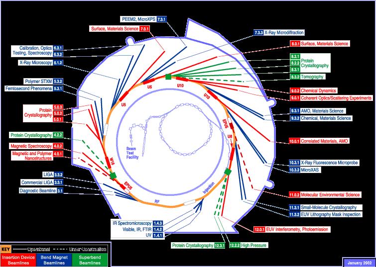
57 Synchrotron radiation 57
58 Interference of photoelectron waves 58 Interference of outgoing and incoming part of photoelectron modulates absorption coefficient 2.3 hω > E abs Correction factor=c/c exp k (Å) Advantages: Atomic-species specific, local bonding environment (length, angle, disorder, neighbor) Disadvantages: very short range (<~5-6 Å), sensitive to multiple scattering, overlapping edges...
59 md ck 2 EXAFS Cu K-edge for Cu metal foil X-ray absorption near edge structure (XANES) m 0 d Extended x-ray absorption fine structure (EXAFS) photon energy (ev) photoelectron wave number (Å -1 ) fk j)( Rk k ksn j j kr j jek e j /)(2 )( 0 sin( 2( )) l 2 kr c FT(ck 2 ) j j For each coordination shell j: R j, N j, 2 j are the sought distance, coord. number and variance of distance (disorder) f j (k)= f j (k) e i j (k) λ is the electron free path, is the scattering amplitude S 0 2 accounts for many-electron excitations. First nearest neighbor 2 nd NN 3 rd NN 4 th NN distance (Å) 59
Fundamentals of X-ray diffraction and scattering
 Fundamentals of X-ray diffraction and scattering Don Savage dsavage@wisc.edu 1231 Engineering Research Building (608) 263-0831 X-ray diffraction and X-ray scattering Involves the elastic scattering of
Diffraction Basics. The qualitative basics:
 The qualitative basics: Diffraction Basics Coherent scattering around atomic scattering centers occurs when x-rays interact with material In materials with a crystalline structure, x-rays scattered in
X-ray Diffraction (XRD)
") هب انم خدا X-ray Diffraction (XRD) 1.0 What is X-ray Diffraction 2.0 Basics of Crystallography 3.0 Production of X-rays 4.0 Applications of XRD 5.0 Instrumental Sources of Error 6.0 Conclusions Bragg s
هب انم خدا X-ray Diffraction (XRD) 1.0 What is X-ray Diffraction 2.0 Basics of Crystallography 3.0 Production of X-rays 4.0 Applications of XRD 5.0 Instrumental Sources of Error 6.0 Conclusions Bragg s
An Introduction to X-Ray Powder Diffraction. credits to: Scott A Speakman, Patrick McArdle Edited by Di Cicco 2014
 An Introduction to X-Ray Powder Diffraction credits to: Scott A Speakman, Patrick McArdle Edited by Di Cicco 2014 LATTICE ARRAYS AND BRAVAIS LATTICES Crystalline materials differ from amorphous materials
X-Ray Diffraction. Nicola Pinna
 X-Ray Diffraction Nicola Pinna Department of Chemistry, CICECO, University of Aveiro, 3810-193 Aveiro, Portugal. School of Chemical and Biological Engineering, College of Engineering, Seoul National University
9/28/2013 9:26 PM. Chapter 3. The structure of crystalline solids. Dr. Mohammad Abuhaiba, PE
 Chapter 3 The structure of crystalline solids 1 2 Why study the structure of crystalline solids? Properties of some materials are directly related to their crystal structure. Significant property differences
Atomic Densities. Linear Density. Planar Density. Linear Density. Outline: Planar Density
 Atomic Densities Outline: Atomic Densities - Linear Density - Planar Density Single- vs poly- crystalline materials X-ray Diffraction Example Polymorphism and Allotropy Linear Density Number of atoms per
Atomic Densities. Linear Density Number of atoms per length whose centers lie on the direction vector for a specific crystallographic direction.
 Atomic Densities Linear Density Number of atoms per length whose centers lie on the direction vector for a specific crystallographic direction. Planar Density Number of atoms per unit area that are centered
9/29/2014 8:52 PM. Chapter 3. The structure of crystalline solids. Dr. Mohammad Abuhaiba, PE
 1 Chapter 3 The structure of crystalline solids 2 Home Work Assignments HW 1 2, 7, 12, 17, 22, 29, 34, 39, 44, 48, 53, 58, 63 Due Sunday 12/10/2014 Quiz # 1 will be held on Monday 13/10/2014 at 11:00 am
LECTURE 7. Dr. Teresa D. Golden University of North Texas Department of Chemistry
 LECTURE 7 Dr. Teresa D. Golden University of North Texas Department of Chemistry Diffraction Methods Powder Method For powders, the crystal is reduced to a very fine powder or microscopic grains. The sample,
This lecture is part of the Basic XRD Course.
 This lecture is part of the Basic XRD Course. Basic XRD Course 1 A perfect polycrystalline sample should contain a large number of crystallites. Ideally, we should always be able to find a set of crystallites
UNIT V -CRYSTAL STRUCTURE
 UNIT V -CRYSTAL STRUCTURE Solids are of two types: Amorphous and crystalline. In amorphous solids, there is no order in the arrangement of their constituent atoms (molecules). Hence no definite structure
X-ray diffraction
 2.2.3.- X-ray diffraction 2.2.3.1.- Origins and fundamentals of the technique The first experimental evidence concerning x-ray diffraction was given by Max von Laue who in 1912 demonstrated that x-rays
Thin Film Scattering: Epitaxial Layers
 Thin Film Scattering: Epitaxial Layers 6th Annual SSRL Workshop on Synchrotron X-ray Scattering Techniques in Materials and Environmental Sciences: Theory and Application May 29-31, 2012 Thin films. Epitaxial
Workshop RIETVELD REFINEMENT OF DIFFRACTION PATTERNS Program Monday June 1st, Introduction to Rietveld refinement S.
 Workshop RIETVELD REFINEMENT OF DIFFRACTION PATTERNS Program Monday June 1st, 2009 9.00 13.00 Introduction to Rietveld refinement S.Enzo Università di Sassari X-ray diffraction for bulk samples and thin
Strain. Two types of stresses: Usually:
 Stress and Texture Strain Two types of stresses: microstresses vary from one grain to another on a microscopic scale. macrostresses stress is uniform over large distances. Usually: macrostrain is uniform
Identification of Crystal Structure and Lattice Parameter. for Metal Powders Using X-ray Diffraction. Eman Mousa Alhajji
 Identification of Crystal Structure and Lattice Parameter for Metal Powders Using X-ray Diffraction Eman Mousa Alhajji North Carolina State University Department of Materials Science and Engineering MSE
Uses of Powder Diffraction. Diffraction
 Powder X-ray X Diffraction Brendan J. Kennedy School of Chemistry The University of Sydney Uses of Powder Diffraction Qualitative Analysis Identification of single-phase materials Identification of multiple
Lecture C4b Microscopic to Macroscopic, Part 4: X-Ray Diffraction and Crystal Packing
 Lecture C4b Microscopic to Macroscopic, Part 4: X-Ray Diffraction and Crystal Packing X-ray Diffraction Max von Laue won the 1914 Nobel Prize for his discovery of the diffraction of x-rays by crystals.
Thin Film Scattering: Epitaxial Layers
 Thin Film Scattering: Epitaxial Layers Arturas Vailionis First Annual SSRL Workshop on Synchrotron X-ray Scattering Techniques in Materials and Environmental Sciences: Theory and Application Tuesday, May
X-RAY DIFFRACTION. X- Ray Sources Diffraction: Bragg s Law Crystal Structure Determination
 X-RAY DIFFRACTION X- Ray Sources Diffraction: Bragg s Law Crystal Structure Determination Part of MATERIALS SCIENCE & ENGINEERING A Learner s Guide AN INTRODUCTORY E-BOOK Anandh Subramaniam & Kantesh Balani
Chapter 3 Basic Crystallography and Electron Diffraction from Crystals. Lecture 9. Chapter 3 CHEM Fall, L. Ma
 Chapter 3 Basic Crystallography and Electron Diffraction from Crystals Lecture 9 Outline The geometry of electron diffraction Crystallography Kinetic Theory of Electron diffraction Diffraction from crystals
9/16/ :30 PM. Chapter 3. The structure of crystalline solids. Mohammad Suliman Abuhaiba, Ph.D., PE
 Chapter 3 The structure of crystalline solids 1 Mohammad Suliman Abuhaiba, Ph.D., PE 2 Home Work Assignments HW 1 2, 7, 12, 17, 22, 29, 34, 39, 44, 48, 53, 58, 63 Due Sunday 17/9/2015 3 Why study the structure
Diffraction: Powder Method
 Diffraction: Powder Method Diffraction Methods Diffraction can occur whenever Bragg s law λ = d sin θ is satisfied. With monochromatic x-rays and arbitrary setting of a single crystal in a beam generally
بسم هللا الرحمن الرحیم. Materials Science. Chapter 3 Structures of Metals & Ceramics
 بسم هللا الرحمن الرحیم Materials Science Chapter 3 Structures of Metals & Ceramics 1 ISSUES TO ADDRESS... How do atoms assemble into solid structures? How does the density of a material depend on its structure?
X-rays were discovered by the German physicist
 Calculating Crystal Structure and Lattice Parameters Using X-ray Diffraction Robert Welch Abstract Certain materials, such as Molybdenum and NaCl, have repeating crystal structures with lattice parameters
Physics 6180: Graduate Physics Laboratory. Experiment CM5: X-ray diffraction and crystal structures
 Physics 6180: Graduate Physics Laboratory Experiment CM5: X-ray diffraction and crystal structures References: Preston and Dietz, Expt. 10 pp. 180-197 Eisberg and Resnick, Quantum Physics, Sec. 9 Kittel,
Materials Lab 1(MT344) X-ray Diffractometer Operation and Data Analysis. Instructor: Dr. Xueyan Wu ( 吴雪艳 )
 X-ray Diffractometer Operation and Data Analysis. Instructor: Dr. Xueyan Wu ( 吴雪艳 )") Materials Lab 1(MT344) X-ray Diffractometer Operation and Data Analysis Instructor: Dr. Xueyan Wu ( 吴雪艳 ) Goals To give students a practical introduction into the use of X-ray diffractometer and data collection.
Materials Lab 1(MT344) X-ray Diffractometer Operation and Data Analysis Instructor: Dr. Xueyan Wu ( 吴雪艳 ) Goals To give students a practical introduction into the use of X-ray diffractometer and data collection.
It is instructive however for you to do a simple structure by hand. Rocksalt Structure. Quite common in nature. KCl, NaCl, MgO
 Today the structure determinations etc are all computer -assisted It is instructive however for you to do a simple structure by hand Rocksalt Structure Quite common in nature KCl, NaCl, MgO 9-1 Typical
Single crystal X-ray diffraction. Zsolt Kovács
 Single crystal X-ray diffraction Zsolt Kovács based on the Hungarian version of the Laue lab description which was written by Levente Balogh, Jenő Gubicza and Lehel Zsoldos INTRODUCTION X-ray diffraction
Basic X-ray Powder Diffraction (XRPD)
") Basic X-ray Powder Diffraction (XRPD) Solid-State, Material Science Crystalline (Scattering : diffraction) Non-crystalline (Scattering) Analytical Tool Qualitative and Quantitative Analysis Quantitative
Basic X-ray Powder Diffraction (XRPD) Solid-State, Material Science Crystalline (Scattering : diffraction) Non-crystalline (Scattering) Analytical Tool Qualitative and Quantitative Analysis Quantitative
Materials Science and Engineering
 Introduction to Materials Science and Engineering Chap. 3. The Structures of Crystalline Solids How do atoms assemble into solid structures? How does the density of a material depend on its structure?
Experiment 2b X-Ray Diffraction* Optical Diffraction Experiments
 * Experiment 2b X-Ray Diffraction* Adapted from Teaching General Chemistry: A Materials Science Companion by A. B. Ellis et al.: ACS, Washington, DC (1993). Introduction Inorganic chemists, physicists,
Example: Compute the wavelength of a 1 [kg] block moving at 1000 [m/s].
![Example: Compute the wavelength of a 1 [kg] block moving at 1000 [m/s].](/thumbs/95/123245062.jpg "Example: Compute the wavelength of a 1 [kg] block moving at 1000 [m/s].") Example: Calculate the energy required to excite the hydrogen electron from level n = 1 to level n = 2. Also calculate the wavelength of light that must be absorbed by a hydrogen atom in its ground state
Example: Calculate the energy required to excite the hydrogen electron from level n = 1 to level n = 2. Also calculate the wavelength of light that must be absorbed by a hydrogen atom in its ground state
Advanced Methods for Materials Research. Materials Structure Investigations Materials Properties Investigations
 Advanced Methods for Materials Research Materials Structure Investigations Materials Properties Investigations Advanced Methods for Materials Research 1. The structure and property of sample and methods
Lecture C4a Microscopic to Macroscopic, Part 4: X-Ray Diffraction and Crystal Packing
 Lecture C4a Microscopic to Macroscopic, Part 4: X-Ray Diffraction and Crystal Packing X-ray Diffraction Max von Laue won the 1914 Nobel Prize for his discovery of the diffraction of x-rays by crystals.
Basic Solid State Chemistry, 2 nd ed. West, A. R.
 Basic Solid State Chemistry, 2 nd ed. West, A. R. Chapter 1 Crystal Structures Many of the properties and applications of crystalline inorganic materials revolve around a small number of structure types
INGE Engineering Materials. Chapter 3 (cont.)
") Some techniques used: Chapter 3 (cont.) This section will address the question how do we determine the crystal structure of a solid sample? Electron microscopy (by direct and indirect observations) Scanning
Some techniques used: Chapter 3 (cont.) This section will address the question how do we determine the crystal structure of a solid sample? Electron microscopy (by direct and indirect observations) Scanning
X-RAY DIFFRACTION IN SEMICONDUCTOR INDUSTRY AND RESEARCH
 X-RAY DIFFRACTION IN SEMICONDUCTOR INDUSTRY AND RESEARCH M. Leszczyński High Pressure Research Center UNIPRESS, Sokolowska 29/37, 01 142 Warsaw, Poland, e-mail: mike@unipress.waw.pl ABSTRACT The paper
High Resolution X-ray Diffraction
 High Resolution X-ray Diffraction Nina Heinig with data from Dr. Zhihao Donovan Chen, Panalytical and slides from Colorado State University Outline Watlab s new tool: Panalytical MRD system Techniques:
Characterization of Materials Using X-Ray Diffraction Powder Diffraction
 Praktikum III, Fall Term 09 Experiment P1/P2; 23.10.2009 Characterization of Materials Using X-Ray Diffraction Powder Diffraction Authors: Michael Schwarzenberger (michschw@student.ethz.ch) Philippe Knüsel
X-Ray Diffraction by Macromolecules
 N. Kasai M. Kakudo X-Ray Diffraction by Macromolecules With 351 Figures and 56 Tables Kodansha ~Springer ... Contents Preface v Part I Fundamental 1. Essential Properties of X-Rays................. 3 1.1
TEM and Electron Diffraction Keith Leonard, PhD (1999) U. Cincinnati
 U. Cincinnati") TEM and Electron Diffraction Keith Leonard, PhD (1999) U. Cincinnati Electron Microscopes: Electron microscopes, such as the scanning electron microscope (SEM) and transmission electron microscope (TEM)
TEM and Electron Diffraction Keith Leonard, PhD (1999) U. Cincinnati Electron Microscopes: Electron microscopes, such as the scanning electron microscope (SEM) and transmission electron microscope (TEM)
The object of this experiment is to test the de Broglie relationship for matter waves,
 Experiment #58 Electron Diffraction References Most first year texts discuss optical diffraction from gratings, Bragg s law for x-rays and electrons and the de Broglie relation. There are many appropriate
X-RAY DIFFRACTIO N B. E. WARREN
 X-RAY DIFFRACTIO N B. E. WARREN Chapter 1 X-Ray Scattering by Atom s 1.1 Classical scattering by a free electron 1 1.2 Polarization by scattering 4 1.3 Scattering from several centers, complex representation
Carbon nanostructures. (http://www.mf.mpg.de/de/abteilungen/schuetz/index.php?lang=en&content=researchtopics&type=specific&name=h2storage)
") Carbon nanostructures (http://www.mf.mpg.de/de/abteilungen/schuetz/index.php?lang=en&content=researchtopics&type=specific&name=h2storage) 1 Crystal Structures Crystalline Material: atoms arrange into a
Carbon nanostructures (http://www.mf.mpg.de/de/abteilungen/schuetz/index.php?lang=en&content=researchtopics&type=specific&name=h2storage) 1 Crystal Structures Crystalline Material: atoms arrange into a
Energy and Packing. typical neighbor bond energy. typical neighbor bond energy. Dense, regular-packed structures tend to have lower energy.
 Energy and Packing Non dense, random packing Energy typical neighbor bond length typical neighbor bond energy r Dense, regular packing Energy typical neighbor bond length typical neighbor bond energy r
Electron Microscopy. Dynamical scattering
 Electron Microscopy 4. TEM Basics: interactions, basic modes, sample preparation, Diffraction: elastic scattering theory, reciprocal space, diffraction pattern, Laue zones Diffraction phenomena Image formation:
Powder X-ray Diffraction
 Powder X-ray Diffraction The construction of a simple powder diffractometer was first described by Hull in 1917 1 which was shortly after the discovery of X-rays by Wilhelm Conrad Röntgen in1895 2. Diffractometer
Lesson 1 X-rays & Diffraction
 Lesson 1 X-rays & Diffraction Nicola Döbelin RMS Foundation, Bettlach, Switzerland February 11 14, 2013, Riga, Latvia Electromagnetic Spectrum X rays: Wavelength λ: 0.01 10 nm Energy: 100 ev 100 kev Interatomic
ECE440 Nanoelectronics. Lecture 08 Review of Solid State Physics
 ECE440 Nanoelectronics Lecture 08 Review of Solid State Physics A Brief review of Solid State Physics Crystal lattice, reciprocal lattice, symmetry Crystal directions and planes Energy bands, bandgap Direct
Introduction to Powder Diffraction/Practical Data Collection
 Durham University Chemistry Department Introduction to Powder Diffraction/Practical Data Collection Dr Ivana Evans Durham, January 2007 Durham Outline Information in a powder pattern What is diffraction
Fundamentals of Crystalline State p. 1 Introduction p. 1 Crystalline state p. 2 Crystal lattice and crystal structure p. 4 Shape of the unit cell p.
 Preface p. xvii Fundamentals of Crystalline State p. 1 Introduction p. 1 Crystalline state p. 2 Crystal lattice and crystal structure p. 4 Shape of the unit cell p. 6 Content of the unit cell p. 7 Asymmetric
Powder X-ray Diffraction. Brendan J. Kennedy School of Chemistry The University of Sydney
 Powder X-ray Diffraction Brendan J. Kennedy School of Chemistry The University of Sydney State of the Art on Earth1912 Bragg s X-ray tube Laue X-ray Diffractometer State of the Art on Mars 2012 Prototype
Fundamentals of Crystalline State and Crystal Lattice p. 1 Crystalline State p. 2 Crystal Lattice and Unit Cell p. 4 Shape of the Unit Cell p.
 Fundamentals of Crystalline State and Crystal Lattice p. 1 Crystalline State p. 2 Crystal Lattice and Unit Cell p. 4 Shape of the Unit Cell p. 7 Crystallographic Planes, Directions, and Indices p. 8 Crystallographic
Key crystallographic concepts: Theory of diffraction. (Crystallography y without tears, Part 1)
") Protein Crystallography (3) Key crystallographic concepts: Theory of diffraction. (Crystallography y without tears, Part 1) Cele Abad-Zapatero University of Illinois at Chicago Center for Pharmaceutical
Protein Crystallography (3) Key crystallographic concepts: Theory of diffraction. (Crystallography y without tears, Part 1) Cele Abad-Zapatero University of Illinois at Chicago Center for Pharmaceutical
X-Ray Diffraction Analysis
 162402 Instrumental Methods of Analysis Unit III X-Ray Diffraction Analysis Dr. M. Subramanian Associate Professor Department of Chemical Engineering Sri Sivasubramaniya Nadar College of Engineering Kalavakkam
Supplemental Exam Problems for Study
 3.091 OCW Scholar Self-Asessment Crystalline Materials Supplemental Exam Problems for Study Solutions Key 3.091 Fall Term 2007 Test #2 page 2 Problem #1 z z y y x x (a) Using proper crystallographic notation
Microstructural Characterization of Materials
 Microstructural Characterization of Materials 2nd Edition DAVID BRANDON AND WAYNE D. KAPLAN Technion, Israel Institute of Technology, Israel John Wiley & Sons, Ltd Contents Preface to the Second Edition
Single vs Polycrystals
 WEEK FIVE This week, we will Learn theoretical strength of single crystals Learn metallic crystal structures Learn critical resolved shear stress Slip by dislocation movement Single vs Polycrystals Polycrystals
Engineering Materials Department of Physics K L University
 Engineering Materials Department of Physics K L University 1 Crystallography Bonding in solids Many of the physical properties of materials are predicated on a knowledge of the inter-atomic forces that
A Brief History of XRD 1895: Röntgen discovers X-Rays received the first Nobel prize in physics in 1901
 X-ray Diffraction A Brief History of XRD 1895: Röntgen discovers X-Rays received the first Nobel prize in physics in 1901 1912: Laue diffracts X-Rays from single crystal 1914 Nobel prize in Physics 1912:
X-ray diffraction and structure analysis Introduction
 Teknillisen fysiikan ohjelmatyö X-ray diffraction and structure analysis Introduction Oleg Heczko 120 100 80 118 12-5 125 Ni-Mn-Ga (298K) SQRT(Intensity) 60 40 20 015 200 123 12-7 20-10 20,10 20-8 040
Metallic crystal structures The atomic bonding is metallic and thus non-directional in nature
 Chapter 3 The structure of crystalline solids Hw: 4, 6, 10, 14, 18, 21, 26, 31, 35, 39, 42, 43, 46, 48, 49, 51, 56, 61 Due Wensday 14/10/2009 Quiz1 on Wensday 14/10/2009 Why study the structure of crystalline
X ray diffraction in materials science
 X ray diffraction in materials science Goals: Use XRD spectra to determine the orientation of single crystals and preferred orientations in a thin film. Understand how grain size and strain affect the
What if your diffractometer aligned itself?
 Ultima IV Perhaps the greatest challenge facing X-ray diffractometer users today is how to minimize time and effort spent on reconfiguring of the system for different applications. Wade Adams, Ph.D., Director,
Bio5325 Fall Crystal Vocabulary
 Crystals and Crystallization Bio5325 Fall 2007 Crystal Vocabulary Mosaicity (mosaic spread) Protein crystals are imperfect, consisting of a mosaic of domains that are slightly misaligned. As a result,
Signals from a thin sample
 Signals from a thin sample Auger electrons Backscattered electrons BSE Incident beam secondary electrons SE Characteristic X-rays visible light 1-100 nm absorbed electrons Specimen electron-hole pairs
Energy and Packing. Materials and Packing
 Energy and Packing Non dense, random packing Energy typical neighbor bond length typical neighbor bond energy r Dense, regular packing Energy typical neighbor bond length typical neighbor bond energy r
Travaux Pratiques de Matériaux de Construction
 Travaux Pratiques de Matériaux de Construction Section Matériaux 6 ème semestre 2009 Etude de Matériaux Cimentaire Par Diffraction des Rayons X Responsable: Silke Ruffing E-Mail: silke.ruffing@epfl.ch
Condensed Matter II: Particle Size Broadening
 Condensed Matter II: Particle Size Broadening Benjamen P. Reed & Liam S. Howard IMAPS, Aberystwyth University March 19, 2014 Abstract Particles of 355µm silicon oxide(quartz)were subjected to a ball milling
Two marks questions and answers. 1. what is a Crystal? (or) What are crystalline materials? Give examples
 What are crystalline materials? Give examples") UNIT V CRYSTAL PHYSICS PART-A Two marks questions and answers 1. what is a Crystal? (or) What are crystalline materials? Give examples Crystalline solids (or) Crystals are those in which the constituent
UNIT V CRYSTAL PHYSICS PART-A Two marks questions and answers 1. what is a Crystal? (or) What are crystalline materials? Give examples Crystalline solids (or) Crystals are those in which the constituent
Kinematical theory of contrast
 Kinematical theory of contrast Image interpretation in the EM the known distribution of the direct and/or diffracted beam on the lower surface of the crystal The image on the screen of an EM = the enlarged
3.091 Introduction to Solid State Chemistry. Lecture Notes No. 5 X-RAYS AND X-RAY DIFFRACTION
 3.091 Introduction to Solid State Chemistry Lecture Notes No. 5 X-RAYS AND X-RAY DIFFRACTION * * * * * * * * * * * * * * * * * * * * * * * * * * * * * * * * * * * * * * * * * * * * * * * * * * Sources
Lectures on: Introduction to and fundamentals of discrete dislocations and dislocation dynamics. Theoretical concepts and computational methods
 Lectures on: Introduction to and fundamentals of discrete dislocations and dislocation dynamics. Theoretical concepts and computational methods Hussein M. Zbib School of Mechanical and Materials Engineering
Chapter One: The Structure of Metals
 Fourth Edition SI Version Chapter One: The Structure of Metals 2010. Cengage Learning, Engineering. All Rights Reserved. 1.1 Importance of the structure: Structures Processing Properties Applications Classification
Physical structure of matter. Monochromatization of molybdenum X-rays X-ray Physics. What you need:
 X-ray Physics Physical structure of matter Monochromatization of molybdenum X-rays What you can learn about Bremsstrahlung Characteristic radiation Energy levels Absorption Absorption edges Interference
TEM imaging and diffraction examples
 TEM imaging and diffraction examples Duncan Alexander EPFL-CIME 1 Diffraction examples Kikuchi diffraction Epitaxial relationships Polycrystalline samples Amorphous materials Contents Convergent beam electron
Packing of atoms in solids
 MME131: Lecture 6 Packing of atoms in solids A. K. M. B. Rashid Professor, Department of MME BUET, Dhaka Today s topics Atomic arrangements in solids Points, directions and planes in unit cell References:
LECTURE 8. Dr. Teresa D. Golden University of North Texas Department of Chemistry
 LECTURE 8 Dr. Teresa D. Golden University of North Texas Department of Chemistry Practical applications for lattice parameter measurements: -determine composition (stoichiometry) of the sample -determine
How can we describe a crystal?
 How can we describe a crystal? Examples of common structures: (1) The Sodium Chloride (NaCl) Structure (LiH, MgO, MnO, AgBr, PbS, KCl, KBr) The NaCl structure is FCC The basis consists of one Na atom and
Lesson 1 Good Diffraction Data
 Lesson 1 Good Diffraction Data Nicola Döbelin RMS Foundation, Bettlach, Switzerland Digital Diffractometers Transmission Geometry Debye-Scherrer Geometry Reflective Geometry Bragg-Brentano Geometry Glass
X-RAY POWDER DIFFRACTION XRD
 X-RAY POWDER DIFFRACTION XRD for the analyst Getting acquainted with the principles Martin Ermrich nλ = 2d sin θ Detlef Opper The Analytical X-ray Company X-RAY POWDER DIFFRACTION XRD for the analyst Getting
A Brief History of XRD 1895: Röntgen discovers X-Rays received the first Nobel prize in physics in 1901
 X-ray Diffraction A Brief History of XRD 1895: Röntgen discovers X-Rays received the first Nobel prize in physics in 1901 1912: Laue diffracts X-Rays from single crystal 1914 Nobel prize in Physics 1912:
ASE324: Aerospace Materials Laboratory
 ASE324: Aerospace Materials Laboratory Instructor: Rui Huang Dept of Aerospace Engineering and Engineering Mechanics The University of Texas at Austin Fall 2003 Lecture 3 September 4, 2003 Iron and Steels
General Objective. To develop the knowledge of crystal structure and their properties.
 CRYSTAL PHYSICS 1 General Objective To develop the knowledge of crystal structure and their properties. 2 Specific Objectives 1. Differentiate crystalline and amorphous solids. 2. To explain nine fundamental
Structure of silica glasses (Chapter 12)
") Questions and Problems 97 Glass Ceramics (Structure) heat-treated so as to become crystalline in nature. The following concept map notes this relationship: Structure of noncrystalline solids (Chapter 3)
Questions and Problems 97 Glass Ceramics (Structure) heat-treated so as to become crystalline in nature. The following concept map notes this relationship: Structure of noncrystalline solids (Chapter 3)
Instrument Configuration for Powder Diffraction
 Instrument Configuration for Powder Diffraction Advanced X-ray Workshop S.N. Bose National Centre for Basic Sciences, 14-15/12/2011 Innovation with Integrity Overview What is the application? What are
Basics of XRD part I. 1 KIT 10/31/17. Name of Institute, Faculty, Department. The Research University in the Helmholtz Association
 Basics of XRD part I Dr. Peter G. Weidler Institute of Functional Interfaces IFG 1 KIT 10/31/17 The Research University in the Helmholtz Association Name of Institute, Faculty, Department www.kit.edu Overview
CRYSTAL LATTICE. Defining lattice: Mathematical construct; ideally infinite arrangement of points in space.
 CRYSTAL LATTICE How to form a crystal? 1. Define the structure of the lattice 2. Define the lattice constant 3. Define the basis Defining lattice: Mathematical construct; ideally infinite arrangement of
Background Statement for SEMI Draft Document 5945 New Standard: Test Method for Determining Orientation of A Sapphire Single Crystal
 Background Statement for SEMI Draft Document 5945 New Standard: Test Method for Determining Orientation of A Sapphire Single Crystal Notice: This background statement is not part of the balloted item.
3. Anisotropic blurring by dislocations
 Dynamical Simulation of EBSD Patterns of Imperfect Crystals 1 G. Nolze 1, A. Winkelmann 2 1 Federal Institute for Materials Research and Testing (BAM), Berlin, Germany 2 Max-Planck- Institute of Microstructure
X-RAY DIFFRACTION CHARACTERIZATION OF MOVPE ZnSe FILMS DEPOSITED ON (100) GaAs USING CONVENTIONAL AND HIGH- RESOLUTION DIFFRACTOMETERS
 GaAs USING CONVENTIONAL AND HIGH- RESOLUTION DIFFRACTOMETERS") 77 X-RAY DIFFRACTION CHARACTERIZATION OF MOVPE ZnSe FILMS DEPOSITED ON (100) GaAs USING CONVENTIONAL AND HIGH- RESOLUTION DIFFRACTOMETERS T.N. Blanton 1), C.L. Barnes 1), M. Holland 1), K.B. Kahen 1),
77 X-RAY DIFFRACTION CHARACTERIZATION OF MOVPE ZnSe FILMS DEPOSITED ON (100) GaAs USING CONVENTIONAL AND HIGH- RESOLUTION DIFFRACTOMETERS T.N. Blanton 1), C.L. Barnes 1), M. Holland 1), K.B. Kahen 1),
SI GUIDE. File Name: Supplementary Information Description: Supplementary Figures, Supplementary Notes and Supplementary References.
 SI GUIDE File Name: Supplementary Information Description: Supplementary Figures, Supplementary Notes and Supplementary References. File Name: Supplementary Movie 1 Description: (the movie from which Figs.
Thin Film Characterizations Using XRD The Cases of VO2 and NbTiN
 Thin Film Characterizations Using XRD The Cases of VO2 and NbTiN A thesis submitted in partial fulfillment of the requirement for the degree of Bachelor of Arts / Science in Physics from The College of
UNIVERSITY OF OSLO. Faculty of Mathematics and Natural Sciences
 Page 1 UNIVERSITY OF OSLO Faculty of Mathematics and Natural Sciences Exam in MENA3100 Characterization of materials Day of exam: 12th. June 2015 Exam hours: 14:30 This examination paper consists of 5
X-ray diffraction. Talián Csaba Gábor University of Pécs, Medical School Department of Biophysics
 X-ray diffraction Talián Csaba Gábor University of Pécs, Medical School Department of Biophysics 2012.10.11. Outline of the lecture X-ray radiation Interference, diffraction Crystal structure X-ray diffraction
CHEM-E5225 :Electron Microscopy Imaging II
 CHEM-E5225 :Electron Microscopy Imaging II D.B. Williams, C.B. Carter, Transmission Electron Microscopy: A Textbook for Materials Science, Springer Science & Business Media, 2009. Z. Luo, A Practical Guide
DIFFRACTION METHODS IN MATERIAL SCIENCE. PD Dr. Nikolay Zotov Tel Room 3N16.
 DIFFRACTION METHODS IN MATERIAL SCIENCE PD Dr. Nikolay Zotov Tel. 0711 689 3325 Email: zotov@imw.uni-stuttgart.de Room 3N16 Lecture 5 OUTLINE OF THE COURSE 0. Introduction 1. Classification of Materials
Travaux Pratiques de Matériaux de Construction. Etude de Matériaux Cimentaires par Diffraction des Rayons X sur Poudre
 Travaux Pratiques de Matériaux de Construction Section Matériaux 6 ème semestre 2015 Etude de Matériaux Cimentaires par Diffraction des Rayons X sur Poudre Study Cementitious Materials by X-ray diffraction