Vibration Control SCHWINGMETALL. The Original Rubber-To-Metal Bonding from ContiTech
|
|
|
- Daisy Pearson
- 6 years ago
- Views:
Transcription

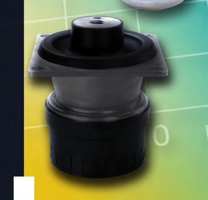


1 Vibration Control SCHWINGMETALL The Original Rubber-To-Metal Bonding from ContiTech
2 ContiTech Vibration Control Innovator and Development Partner ContiTech is an innovator and development partner for vibration-damping applications in the automotive industry for special vehicles, motor-drive mechanisms, machinery and equipment. The demands on modern, stationary machinery in regards to vibration and noise are very diverse. We work using modern methods in compliance with the current requirement concerning environmental sustainability and the preservation of resources. We view vehicles as a total system. For us, competence in chassis design means optimal tuning of all components amongst each other. With our holistic approach as well as our extensive system, product and application know-how, we meet these requirements while at the same time conserving resources and protecting the environment. Bearing in mind the needs of our partner and customers, we show a high awareness regarding quality, costs and reliable logistics. SCHWINGMETALL q damps vibrations and structure-borne sound q insulates machine vibrations q reduces accelerations q provides noise protection


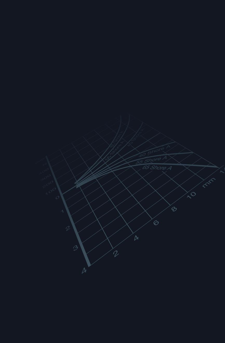
3 Layout of Elastic Mounting Choice of SCHWINGMETALL Parts in Five Steps: 1. For the layout of a mount, first the excitation vibration range and the insulation degree are evaluated. An insulation degree of more than 75% should be aimed for. During the evaluation of the diagram, the linear static spring deflection and the natural frequency of the system are depicted at the intersection of the excitation vibration value and the insulation degree. 2. The depicted linear static spring deflection and the force affecting the viewed supporting point are the basis for the calculation of the required spring travel: N spring stiffness c = mm load F spring travel s 4. In the table of the chosen part group, please choose a part that has a higher spring stiffness and max. load in the viewed direction than arise at the supporting point. 5. Finally, the following formula can be used to calculate the actual insulation degree: 1 isolation degree η = 1- excitation vibration range v err natural frequency v e The chapter Characteristics and Theory contains detailed explanations and examples of elastic mount layouts (see pages ) In the chapter Products and Applications, you can choose part types that best fit the intended use (see pages 8-13). linear static spring travel excitation vibration vibration insulation over critical range resonance line no vibration insulation subcritical range Insulation degree η and insulation value D of an undamped single mass oscillator depending on excitation and natural frequency range resp. on the linear static spring travel. natural frequency 3
4 Instructions for Catalog Use Technical Details The product descriptions in the catalog contain the following details. Dimensions The dimensions are shown either next to the part charts or similar parts in the tables. Spring Stiffness Spring stiffness is calculated on the basis of the three spatial directions. For parts exposed to impact stress, the data is displayed as force and energy range diagrams. Max. Loads Maximum loads refer to static loads that may be superimposed by dynamic forces. In some special cases, higher loads may be authorized upon request. Mass Mass refers to a certain part and is a guide value. Elastomer Natural rubber is used as a standard elastomer in the SCHWINGMETALL products in the given hardness ranges. If other elastomers are used, the respective elastomer is specially listed. Mould No. The mould number describes the geometry of the part. Ordering Instructions The SCHWINGMETALL product range covers a very wide range of applications and is divided into the part groups Classic, Classic Plus and Premium. Please observe the following instructions for your inquiries or orders. The part number is required for inquiries or orders for standard parts. The following information must also be submitted: q part description q mould number q elastomer hardness For special applications, special elastomer hardnesses or materials (e. g. chloroprene or nitrile rubber) can be provided. Special metal parts can also be delivered. These parts that must be specially manufactured can be delivered upon request. ContiTech also delivers special parts made-to-order. Please contact our sales department. Online Catalog For further information, please refer to our online catalog at Part No. The part number is required for the order because the geometry, elastomer type and hardness are defined by it. Directions of Loading In the tables, the directions of loading of each part are depicted. The third direction is shown vertically in comparison to the other two. If only one direction of loading is shown, the part should only be strained in this direction. h I g Ød Compression Mounts AK Type d Dimensions h l g C x Spring Stiffness C y C z F x Max. Load Mass Elastomer Form No. Part No M F y F z Piece [kg] Hardness [Shore A] Load Directions X 4


5 q Contents Instructions for Catalog Use Products and Applications 8 13 SCHWINGMETALL Classic q Compression Mounts q Railstrips q Buffers SCHWINGMETALL Classic Plus q Cone Mounts q Dome Mounts q Flanged Mounts q Angled Mounts q Torsion Mounts q Special Mounts SCHWINGMETALL Premium q Hydromounts SCHWINGMETALL Characteristics and Theory


6 q Products and Applications Vibration Control Solutions - From Layout to Production Standard products for economic solutions Our rubber-to-metal bonded parts reduce vibrations and structure-borne sound, insulate machine vibrations, reduce accelerations and protect against noise. Optimal material choice and state-of-the-art production processes guarantee economically convincing product solutions tailored to suit market needs that fulfill every type of requirement of the automotive industry as well as in the machine and apparatus construction field. The SCHWINGMETALL product program contains 500 standard parts. Special requirements can therefore be quickly met. 6


7 SCHWINGMETALL Classic The tried and tested basic products of recognized quality, e. g. compression mounts. They are functional, flexible and universally useable where there is need for the resilient support or lightweight to medium-weight masses in all areas of building machinery, equipment and engines. A large range of types and sizes with various metal-part connections allows limitless designs for various applications. SCHWINGMETALL Classic Plus The technically enhanced products with added benefits, e. g. combi mounts. They increase the functionality and are suitable for inclined mounting situations involving lateral forces. They provide excellent lateral stability of the masses they support at natural frequencies down to 3.7 Hz. When bolted to a machine and it base plate, they are particularly effective giving the same spring values vertically and horizontally. SCHWINGMETALL Premium Products and modules with advanced properties and functions, e. g. hydraulic mounts or springs. They provide reliable solutions at the highest technical level in the resilient support of all types of machinery, equipment and engines. They are suitable for units and apparatus with continuous and intermittent excitation forces. They minimize the transmission of vibrations in engine mounts, cabs and gear boxes etc. and have exceptional damping properties. 7

8 q Products and Applications Products and Applications SCHWINGMETALL Classic SCHWINGMETALL Compression Mounts preferred for mounting of lightweight or medium-weight masses in all fields of building machinery, equipment and engines. A wide range of types and sizes with various metal part connections allows limitless designs for various applications. Mass per Element 1) Natural Frequency 2) from to from Type A, B, C Standard element for various applications for normal application requirements. Pressure and thrust resistant. Various metal part connections for limitless designs. 5 kg 1700 kg 300 min -1 Type AK For heavy masses with small dimensions. 30 kg 450 kg 300 min -1 Type D, S Non-screw attachment for assembly of equipment with low excitation forces. 90 kg 400 kg 300 min -1 SCHWINGMETALL Railstrips (Type 1 and 2) especially for mounting of heavy or heaviest machines, aggregates and foundations. A structured program for individual solutions. The railstrip lengths can be adapted to the respective loads. Therefore, SCHWINGMETALL railstrips are especially suitable for mounting different loads at each mounting point. Mass per Element 1) Natural Frequency 2) from to from Type 1, 2 All-purpose mounts for very heavy masses. Choice of railstrip length allows load adaption. Therefore well suited for mounting with asymmetrical center of gravity. 160 kg 4000 kg 300 min -1 U-Shaped Railstrip Medium range of natural frequency in vertical direction with very good lateral stability. Choice of railstrip length allows load adaption. Therefore well suited for mounting with asymmetrical center of gravity. 20 kg 150 kg 360 min -1 1) Masses refer to maximum loads. 2) The natural frequency rates refer to the lowest standard elastomer hardness at maximum load. 8


9 SCHWINGMETALL Classic Products and Applications SCHWINGMETALL Buffers are used together with elastic mounts in order to limit vibration amplitudes. Special designs suited for soft absorption of moving masses with high kinetic energy. Impact Mounts Heavy-duty impact mounts Parabolic spring Buffer part with medium-sized spring rates for the absorption of medium-sized energy. Buffer part for the absorption of high energy values at high ultimate power rates. Buffer part with soft characteristic curves. Large spring rates and high ultimate power rates for high amount of energy absorption. SCHWINGMETALL Classic Plus SCHWINGMETALL Cone Mounts All-purpose equipment mounts for medium-weight loads. A good lateral stability is attained with the high radial stiffness with regard to axial stiffness. Respective washers delivered for bearing surfaces resp. breakaway control. Mass per Element 1) Natural Frequency 2) from to from High axial spring rates and good radial behavior, suited for medium-sized loads. 20 kg 500 kg 390 min -1 SCHWINGMETALL Dome Mounts solve the problems of level regulated machine and equipment mounting with non screw attachment. By means of level regulation, machines and equipment can be aligned exactly according to height. The underlay makes mounting with non screw attachment possible. For light up to medium-weight shear forces. Mass per Element 1) Natural Frequency 2) from to from Dome Mounts Heavy-duty spring mounts. Almost equal spring rates in vertical and lateral direction. 30 kg 2000 kg 430 min -1 Dome Mounts AS Series Dome mount with tear off safety and square flange with 4 base screw attachments. 150 kg 1000 kg 430 min -1 Dome Mounts C Series Square dome mount with 2 base screws. 30 kg 750 kg 380 min -1 1) Masses refer to maximum loads. 2) The natural frequency rates refer to the lowest standard elastomer hardness at maximum load. 9

10 q Products and Applications SCHWINGMETALL Classic Plus SCHWINGMETALL Flange Mounts are simple to install robust mounts for medium-weight loads. Installation with washers on top and on the bottom guarantees tear off safety. The washers are not part of the scope of delivery. Mass per Element 1) Natural Frequency 2) from to from Flange Mounts Flange Mounts B Series Adjusting the required washers makes the mount more sturdy in pressure and tension directions. Adjusting the required washers makes the mount more sturdy in pressure and tension directions. 60 kg 240 kg 300 min kg 460 kg 650 min -1 SCHWINGMETALL Inclined Mounts with compression mounts or railstrips are designed for inclined mounting and natural frequencies up to 3.7 Hz with very good lateral stability. Designs for loads of 100 kg up to 4,500 kg per part make combinations for mounts for supported parts of any size with variable and simple installation possible. Installation Instruction: Inclined mounts cause shear forces due to a wedge effect that must be absorbed by the base plate. The shear force per element may be of a maximum equal to the vertical force (F Qmax = F H ). Mass per Element 1) Natural Frequency 2) from to from Combi Mounts with Compression Mounts Same spring characteristics in vertical and lateral directions. Low natural frequency. Very good stability of mounted masses in lateral direction. 100 kg 400 kg 220 min -1 Combi Mounts with Railstrips Same spring characteristics in vertical and lateral directions. Low natural frequency. Very good stability of mounted masses in lateral direction. Distinctly heavier masses than combi part with buffer. 750 kg 4500 kg 220 min -1 Angled Railstrips Same spring characteristics in vertical and lateral directions. Low natural frequency. Very good stability of mounted masses in lateral direction. 250 kg 900 kg 250 min -1 1) Masses refer to maximum loads. 2) The natural frequency rates refer to the lowest standard elastomer hardness at maximum load. 10
 Natural Frequency 2) from to from Principally for distortion wear. Also suited for lateral loads.")
11 SCHWINGMETALL Classic Plus Products and Applications SCHWINGMETALL Torsion Mounts Ring Mounts The four part outer ring is pressed into an undersized bored hole. In this way, a shaft installed in the inner bushing will be elastically mounted. Mass per Element 1) Natural Frequency 2) from to from Principally for distortion wear. Also suited for lateral loads. 40 kg 190 kg 670 min -1 Torsion Bushings Torque can be transmitted shock-free by means of torsion bushings. The elasticity of this bushing allows small alignment and angle defects on both shaft ends. Mass per Element 1) Natural Frequency 2) from to from Principally for distortion wear. Also suited for lateral loads. 40 kg 190 kg 670 min -1 Torsion Mounts are designed to fasten shaft ends elastically on flat surfaces. This part allows axial, radial, torsional and gimbaled movements, each with their own specific spring stiffness. Mass per Element 1) Natural Frequency 2) from to from Maintenance-free, elastic hinge bearing. Simple installation. 80 kg 200 kg 770 min -1 1) Masses refer to maximum loads. 2) The natural frequency rates refer to the lowest standard elastomer hardness at maximum load. 11
 Natural Frequency 2) from to from Parts with tear off safety for absorption of statical tensile forces. 10 kg 300 kg 360 min -1 Heavy-Duty Mounts are all-purpose equipment mounts.")
12 q Products and Applications SCHWINGMETALL Classic Plus SCHWINGMETALL Special Mounts Bell Mounts designed as mounts for hanging masses. Mass per Element 1) Natural Frequency 2) from to from Parts with tear off safety for absorption of statical tensile forces. 10 kg 300 kg 360 min -1 Heavy-Duty Mounts are all-purpose equipment mounts. They are generally installed to maintain static load in the z direction. In this way, a convenient coordination in the vertical direction, stability in the lateral direction (good, if this is the driving direction in case of mount problems in vehicles) and softness in the lateral direction are achieved. Heavy-duty mounts can be delivered with tear off safety. Mass per Element 1) Natural Frequency 2) from to from Different spring rates for the three spatial directions. 70 kg 1000 kg 330 min -1 Instrument Mounts This design is suited for light masses. Ensures same stiffness in vertical and lateral directions. Mass per Element 1) Natural Frequency 2) from to from Suited for mounting light masses with low natural frequencies. 10 kg 220 kg 260 min -1 Shear Mounts Especially suited for mounting light masses with low natural frequencies. These parts protect e. g. sensitive instruments, measuring and display equipment or switch cabinets against vibrations. Mass per Element 1) Natural Frequency 2) from to from Suited for mounting light masses with low natural frequencies. 8 kg 25 kg 200 min -1 1) Masses refer to maximum loads. 2) The natural frequency rates refer to the lowest standard elastomer hardness at maximum load. 12
. This is achieved by hydraulic damping.")
13 SCHWINGMETALL Premium Products and Applications SCHWINGMETALL Hydromounts Hydromounts V Series These components are suited for light to medium-weight masses and especially interesting, if, besides vibrations, interfering impacts arise and the natural frequencies of the system should subside quickly (example: cabin mounts in industrial trucks). This is achieved by hydraulic damping. Mass per Element 1) Natural Frequency 2) from to from Mounts with integrated hydraulic damping. Also designed to absorb impact energy. 10 kg 400 kg 370 min -1 Hydromounts V plus Series This hydromount is characterized by an integrated, broadband damping in the vertical direction and therefore damps impacts especially well. Furthermore, it has an integrated stopper disk. Mainly used for cabin mounting for forklifts as well as engine mounts for various industrial vehicles. Mass per Element 1) Natural Frequency 2) from to from Hydromount V 1500 plus with compact design and integrated hydraulic damping. 50 kg 250 kg 420 min -1 Hydromounts K Series Robust Hydromount K series with tear off safety. Especially designed as a mount for heavy construction vehicle cabins due to its high transverse rigidity and hydraulic damping in the vertical direction. May also be used as mount for large machines. Also available without hydraulic damping with the same mounting dimensions. Mass per Element 1) Natural Frequency 2) from to from Mounts for middle-weight masses with good lateral stability. 100 kg 350 kg 390 min -1 1) Masses refer to maximum loads. 2) The natural frequency rates refer to the lowest standard elastomer hardness at maximum load. 13

14 q SCHWINGMETALL Classic SCHWINGMETALL Compression Mounts h l g Ø d Compression Mounts A Type d Dimensions h l g C x Spring Stiffness C y C z F x Max. Loads Mass Elastomer Mould No. Part No. F y F z Piece [kg] Hardness [Shore A] M /A M /A M /A M /A M /A M /A M /A M /A M /A M /A M /A M /A M /A M /A M /A M a/A M a/A M a/A M /A M /A M /A M /A M /A M /A M /A M /A M /A M /A M /A M /A M /A M /A M /A M /A M /A M /A
15 Compression Mounts Compression Mounts A Type d Dimensions h l g C x Spring Stiffness C y C z F x Max. Loads Mass Elastomer Mould No. Part No. F y F z Piece [kg] Hardness [Shore A] M /A M /A M /A M /A M /A M /A M /A M /A M /A M a/A M a/A M a/A M /A M /A M /A M b/A M b/A M b/A M /A M /A M /A M /A M /A M /A M /A M /A M /A M /A M /A M /A M /A M /A M /A Directions of Loading X 15


16 q SCHWINGMETALL Classic SCHWINGMETALL Compression Mounts I2 h I1 g Ø d Compression Mounts B Type d h Dimensions l1 l2 g C x Spring Stiffness C y C z F x Max. Loads Mass Elastomer Mould No. Part No. F y F z Piece [kg] Hardness [Shore A] M /B M /B M /B M /B M /B M /B M /B M /B M /B M a/B M a/B M a/B M /B M /B M /B M /B M /B M /B M /B M /B M /B M /B M /B M /B M /B M /B M /B M /B M /B M /B
17 Compression Mounts Compression Mounts B Type d h Dimensions l1 l2 g C x Spring Stiffness C y C z F x Max. Loads Mass Elastomer Mould No. Part No. F y F z Piece [kg] Hardness [Shore A] M /B M /B M /B M /B M /B M /B M /B M /B M /B M /B M /B M /B M /B M /B M /B M /B M /B M /B M /B M /B M /B M /B M /B M /B M /B M /B M /B Directions of Loading X 17

18 q SCHWINGMETALL Classic SCHWINGMETALL Compression Mounts h I g Ød Compression Mounts C Type d Dimensions h l g C x Spring Stiffness C y C z F x Max. Loads Mass Elastomer Mould No. Part No. F y F z Piece [kg] Hardness [Shore A] M /C M /C M /C M /C M /C M /C M /C M /C M /C M /C M /C M /C M /C M /C M /C M /C M /C M /C M /C M /C M /C M /C M /C M /C M /C M /C M /C M /C M /C M /C
19 Compression Mounts Compression Mounts C Type d Dimensions h l g C x Spring Stiffness C y C z F x Max. Loads Mass Elastomer Mould No. Part No. F y F z Piece [kg] Hardness [Shore A] M /C M /C M /C M /C M /C M /C ) /C ) /C ) /C ) /C ) /C ) /C ) /C ) /C ) /C ) suitable for screw up to M20; diameter of the inner part 40 mm Directions of Loading X 19


20 q SCHWINGMETALL Classic SCHWINGMETALL Compression Mounts h I g Ød Compression Mounts AK Type d Dimensions h l g C x Spring Stiffness C y C z F x Max. Loads Mass Elastomer Mould No. Part No. F y F z Piece [kg] Hardness [Shore A] M M M M M M M M M M M M Directions of Loading X 20
21 g h l Compression Mounts Ø d Compression Mounts AK Type d Dimensions h l g C x Spring Stiffness C y C z Max. Loads Mass Elastomer Mould No. Part No. F z Piece [kg] Hardness [Shore A] M /D M /D M /D M /D M a/D M /D M /D M /D M /D M /D M /D M /D M /D M /D M /D M /D M /D M /D Directions of Loading X 21

22 q SCHWINGMETALL Classic SCHWINGMETALL Compression Mounts g h l Ø d Compression Mounts S Type d Dimensions h l g C x Spring Stiffness C y C z Max. Loads Mass Elastomer Mould No. Part No. F z Piece [kg] Hardness [Shore A] M /S M /S M /S M /S M /S M /S M /S M /S M /S Directions of Loading X 22
23 23 Compression Mounts

24 q SCHWINGMETALL Classic SCHWINGMETALL Railstrips s h b Railstrips Type 1 Dimensions Spring Stiffness 1) max. Loads 1) Min. Natural Frequency 2) Mass Elastomer Mould No. Part No. b h Length s C x,y C z F x,y F z ν e min-1 Piece [kg] Hardness [Shore A] a f g b a a a a c d a b b a d c ) The indicated stiffness and maximum loads refer to a railstrip 10 mm long. 2) The minimal natural frequency values refer to maximum loads. made-to-order item Tolerance reference dimension see drawing at 24
25 Railstrips Railstrips Type 1 Dimensions Spring Stiffness 1) max. Loads 1) Min. Natural Frequency 2) Mass Elastomer Mould No. Part No. b h Length s C x,y C z F x,y F z ν e min-1 Piece [kg] Hardness [Shore A] b a b a c b a ) The indicated stiffness and maximum loads refer to a railstrip 10 mm long. 2) The minimal natural frequency values refer to maximum loads. made-to-order item Tolerance reference dimension see drawing at Directions of Loading X 25


26 SCHWINGMETALL Railstrips s h b2 b1 Railstrips Type 2 Dimensions Spring Stiffness 1) max. Loads 1) Min. Natural Frequency 2) Mass Elastomer Mould No. Part No. b1 b2 h Length s C x,y C z F x,y F z ν e min-1 Piece [kg] Hardness [Shore A] b a a a a b a ) The indicated stiffness and maximum loads refer to a railstrip 10 mm long. 2) The minimal natural frequency values refer to maximum loads. made-to-order item Tolerance reference dimension see drawing at Directions of Loading X 26

 The indicated stiffness and maximum loads refer to a railstrip 10 mm long.")
27 b 3 h2 s h1 b 2 s b 1 Railstrips Railstrips U-Shaped Dimensions Spring Stiffness 1) max. Loads 1) Min. Natural Frequency 2) Mass Elastomer Mould No. Part No. b1 b2 b3 h1 h2 Length s C x C y,z F x F y,z ν e min-1 Piece [kg] Hardness [Shore A] ) The indicated stiffness and maximum loads refer to a railstrip 10 mm long. 2) The minimal natural frequency values refer to maximum loads. Directions of Loading X 27
![SCHWINGMETALL Impact Mounts h I q SCHWINGMETALL Classic Ø d g Impact Mounts with Internal Thread d h Dimensions l g F z Max. Loads W Mass Piece [kg] Elastomer Hardness [Shore A] Mould No.](/docs-images/75/71776507/images/28-2.jpg "Part No. 52 35 8.8 M10 3874 23.000 0.085 55 38652 3915250000 83 60 11.6 M12 11572 120.000 0.340 55 38653 3915251000 125 90 17.5 M16 29148 380.000 1.200 55 38654 3915252000 Direction of Loading 28")
28 SCHWINGMETALL Impact Mounts h I q SCHWINGMETALL Classic Ø d g Impact Mounts with Internal Thread d h Dimensions l g F z Max. Loads W Mass Piece [kg] Elastomer Hardness [Shore A] Mould No. Part No M M M Direction of Loading 28
29 Force and Energy Direction Diagrams Mould No Mould No Mould No Impact Energy W [Nm] Impact Force F [kn] Shore A 55 Shore A Spring Travel s Impact Energy W [Nm] Impact Force F [kn] Shore A 55 Shore A Spring Travel s Impact Energy W [Nm] Impact Force F [kn] Shore A 55 Shore A Spring Travel s Buffers 29
![q SCHWINGMETALL Classic SCHWINGMETALL Impact Mounts h I g Ød Impact Mounts with Outside Thread d h Dimensions l g F z Max. Loads W Elastomer Hardness [Shore A] 25 16.5 18.5 M6 991 3.2 0.](/docs-images/75/71776507/images/30-1.jpg "015 40 25444 25 16.5 18.5 M6 953 2.5 0.015 55 25444 3915209000 25 16.5 18.5 M6 1173 2.2 0.015 65 25444 50 17.0 28.0 M10 3586 5.4 0.077 40 25481 50 17.0 28.0 M10 3909 5.5 0.077 55 25481 3915216000 50 17.")
30 q SCHWINGMETALL Classic SCHWINGMETALL Impact Mounts h I g Ød Impact Mounts with Outside Thread d h Dimensions l g F z Max. Loads W Elastomer Hardness [Shore A] M M M M M M M M M M Mass Piece [kg] Mould No. Part No. made-to-order item Direction of Loading 30
31 Force and Energy Direction Diagrams Mould No Mould No Impact Energy W [Nm] Impact Force F Shore A 65 Shore A 55 Shore A 40 Shore A 40 Shore A 55 Shore A Spring Travel s Impact Energy W [Nm] Impact Force F [kn] Shore A 65 Shore A 55 Shore A 40 Shore A 40 Shore A 55 Shore A Spring Travel s Buffers Mould No Mould No Impact Energy W [Nm] Impact Force F [kn] Shore A 65 Shore A 55 Shore A 55 Shore A 40 Shore A 40 Shore A Spring Travel s Impact Energy W [Nm] Impact Force F [kn] Shore A 55 Shore A Spring Travel s 31
 50 2 x 8.5 35 70 130 5 10100 40 0.360 55 25081b/AN 3973501000 100 1) 50 2 x 8.5 70 70 130 5 9614 89 0.")
32 q SCHWINGMETALL Classic SCHWINGMETALL Heavy-Duty Impact Mounts I1 s h I2 a2 b Ød a 1 Heavy-Duty Impact Mounts a1 a2 b Dimensions d h l1 l2 s Max. Loads Mass Elastomer Mould No. Part No. F z W Piece [kg] Hardness [Shore A] 100 1) 50 2 x b/AN ) 50 2 x /AN x /AN x /AN x b/AN x /AN x b/AN x /AN ) a2 without value means only one hole bored in the center. Direction of Loading 32
33 Force and Energy Direction Diagrams Mould No b/AN Mould No /AN Mould No /AN Impact Energy W [Nm] Impact Force F [kn] Shore A 55 Shore A Spring Travel s Impact Energy W [Nm] Impact Force F [kn] Shore A 55 Shore A Spring Travel s Impact Energy W [Nm] Impact Force F [kn] Shore A 55 Shore A Spring Travel s Buffers Mould No /AN Mould No b/AN Mould No /AN Impact Energy W [Nm] Impact Force F [kn] Shore A 55 Shore A Spring Travel s Impact Energy W [kn] Impact Force F [kn] Shore A 55 Shore A Spring Travel s Impact Energy W [kn] Impact Force F [kn] Shore A 55 Shore A Spring Travel s Mould No b/AN Mould No /AN Impact Energy W [Nm] Impact Force F [kn] Shore A 55 Shore A Spring Travel s Impact Energy W [kn] Impact Force F [kn] Shore A 55 Shore A Spring Travel s 33
34 q SCHWINGMETALL Classic SCHWINGMETALL Impact Mounts h I g Ø d Parabolic spring d h Dimensions l g F z Max. Loads W Mass Piece [kg] Elastomer Hardness [Shore A] Mould No. Part No M M M M M M Direction of Loading 34
35 Force and Energy Direction Diagrams Mould No Mould No Mould No Impact Energy W [Nm] Impact Force F Shore A 55 Shore A Spring Travel s Impact Energy W [Nm] Impact Force F Shore A 55 Shore A Spring Travel s Impact Energy W [Nm] Impact Force F [kn] Shore A 55 Shore A Spring Travel s Buffers Mould No Mould No Mould No Impact Energy W [Nm] Impact Force F [kn] Shore A 55 Shore A Spring Travel s Impact Energy W [Nm] Impact Force F [kn] Shore A 55 Shore A Spring Travel s Impact Force F [kn] Impact Energy W [Nm] Shore A 55 Shore A Spring Travel s 35


36 q SCHWINGMETALL Classic Plus SCHWINGMETALL Cone Mounts Ø 30 Ø Ø 11 Ø 30 Ø Ø Ø 51 Mould No Ø 51 Mould No Cone Mounts C x Spring Stiffness C y C z F x Max. Loads F y F z Mass Piece [kg] Elastomer Hardness [Shore A] Mould No. Part No A A A


37 Ø Ø 37 Ø Cone Mounts Ø 16 Ø 74.6 Ø 10.3 Mould No Ø 74.6 Ø 10.3 Mould No A Mould No Mould No Mould No See pages Directions of Loading Directions of Loading Directions of Loading Directions of Loading X X X X 37


38 q SCHWINGMETALL Classic Plus SCHWINGMETALL Cone Mounts Ø 36.7 Ø Ø 38 Ø Ø 16 Ø 74.6 Ø 10.3 Mould No Ø 74.6 Ø 10.3 Mould No see page 36 for cone mount table Directions of Loading Directions of Loading X X 38


39 20 Ø 48 M 16 Ø Ø 12 Mould No Cone Mounts Ø Directions of Loading X 39


40 q SCHWINGMETALL Classic Plus SCHWINGMETALL Dome Mounts M10 Mould No Ø M M10 SW24 Ø Mould No Dome Mounts Dimensions a b d1 d2 e g h s1 s2 s3 Washer DIN 9021-ST x 9 SW8 M A13x x 9 SW8 M A13x x 9 SW8 M A13x x 13 SW10 M A17x x 13 SW10 M A17x x 13 SW10 M A17x x 13 SW14 M A21x x 13 SW14 M A21x x 13 SW14 M A21x4 Wet the studs with soapy water before mounting the underlay. Nuts according to DIN 555, washers according to DIN 25 and spring washers according to DIN 127 are commercial parts. Directions of Loading X Directions of Loading X 40


41 Mould No , 33629, a b s1 h I d 1 g g e s2 d 2 s3 a b Dome Mounts Mould No , 33629, C x Spring Stiffness C y C z F x Max. Loads F y F z Mass Piece [kg] Elastomer Hardness [Shore A] Mould No. Part No Part No. Level Adjustment Spindle Part No. Washer Mat Mount Directions of Loading X 41


42 q SCHWINGMETALL Classic Plus SCHWINGMETALL Dome Mounts b a d2 d 1 s h g Dome Mounts AS Series a b d1 Dimensions d x 9 M x 9 M x 9 M x 13 M x 13 M x 13 M g h s Mount with integrated stop disk 42
43 C x Spring Stiffness C y C z F x Max. Loads F y F z Mass Piece [kg] Elastomer Hardness [Shore A] Mould No. Part No Resp. Underlays and Level Adjustment Spindles see page 40 Dome Mounts Directions of Loading X 43


44 q SCHWINGMETALL Classic Plus SCHWINGMETALL Dome Mounts b 2 b 1 a h2 s h1 I1 I3 I4 I2 I 4 g I 5 Dome Mounts C Series a b1 b2 g h1 Dimensions h M M M M M M M M M l1 l2 l3 l4 l5 s Mount with integrated stop disk 44
45 C x Spring Stiffness C y C z F x Max. Loads F y F z Mass Piece [kg] Elastomer Hardness [Shore A] Mould No. Part No Dome Mounts Resp. Level Adjustment Spindles see page 40 Directions of Loading X 45
 70 48 47 23.0 12 22 9 40 28 90 81) 94 71 68 33.0 16 37 65 9 54 33 117 5 94 71 68 39.0 16 37 65 9 49 28 117 5 94 71 68 52.")


46 q SCHWINGMETALL Classic Plus SCHWINGMETALL Flange Mounts d 1 d 2 d 3 I a h1 h2 d 6 s b d 4 d 5 Flange Mounts a b d1 d2 d3 Dimensions d ) ) ) plastic flange d5 d6 h1 h2 l s Installation Instruction The disks a depicted in both installation examples are required for correct function, but are not included in the scope of supply. The diameter of the disks must not be less than d1-5 mm. Installation Example The static load affects the higher spring part in both cases. 46
47 Spring Stiffness C x,y C z Max. Loads F x,y F z F impact load X,Y Max. Impact Load2) Elastomer Hardness [Shore A] / ) / ) / / / / / / / / / ) Maximum impact load at nominal load. 3) During impact load procedure, the plastic flanges must be well reinforced. F impact load Mass Piece [kg] Mould No. Part No. made-to-order item Flange Mounts Directions of Loading X 47

48 q SCHWINGMETALL Classic Plus SCHWINGMETALL Flange Mounts Ød 1 Ød 2 Ød 3 h2 h1 Flange Mounts B Series d1 d2 d3 d4 d5 Dimensions h min M min M min M min M min M min M min M min M min M20 h2 h3 s r g 48
49 d 4 Spring Stiffness Max. Loads Mass Elastomer Mould No. Part No. C x,y C z F z Hardness [Shore A] Piece [kg] Flange Mounts s h3 r g d 5 Directions of Loading X/Y 49


50 q SCHWINGMETALL Classic Plus SCHWINGMETALL Angled Mounts h Ød 2 Ød 1 s a 1 b 1 b 2 a 2 Combi Mounts L with Compression Mounts a1 a2 b1 b2 Dimensions d1 d2 h s 50
51 C x Spring Stiffness C y C z F x Max. Loads F y Elastomer Hardness [Shore A] /A /A /A /A /A /A /A /A /A a/A a/A a/A /A /A /A b/A b/A b/A /A /A /A /A /A /A /A /A /A F z Mass Piece [kg] Mould No. Part No. Angled Mounts made-to-order item Directions of Loading Y 51


52 h1 q SCHWINGMETALL Classic Plus SCHWINGMETALL Angled Mounts h2 Ød 1 s Ød 2 a 1 a 2 b 1 b 2 Combi Mounts with Compression Mounts a1 a2 b1 b2 Dimensions d d2 h1 h2 s 52
53 C x Spring Stiffness C y C z F x Max. Loads F y Elastomer Hardness [Shore A] /A /A /A /A /A /A /A /A /A a/A a/A a/A /A /A /A b/A b/A b/A /A /A /A /A /A /A /A /A /A F z Mass Piece [kg] Mould No. Part No. Angled Mounts made-to-order item Directions of Loading Y 53


54 q SCHWINGMETALL Classic Plus SCHWINGMETALL Angled Mounts a 3 a 2 h b 1 s Ød a 1 l 1 b 2 l 2 Combi Mounts L with Railstrip a1 a2 a3 b1 b2 Dimensions x x x x x x x x x x x x x x x x x x d h l1 l2 s l1 short design l2 long design 54
55 C x Spring Stiffness C y C z F x Max. Loads F y Elastomer Hardness [Shore A] a a c c d d a a b b c c F z Mass Piece [kg] Mould No. Part No. made-to-order item Angled Mounts Directions of Loading Y 55


56 h1 q SCHWINGMETALL Classic Plus SCHWINGMETALL Angled Mounts b 1 s h2 a 1 b 2 Ød a 2 a 3 l 1 l 2 Combi Mounts with Railstrip a1 a2 a3 b1 b2 Dimensions d x x x x x x x x x x x x x x x x x x h1 h2 l1 l2 s l1 short design l2 long design 56
57 C x Spring Stiffness C y C z F x Max. Loads F y Elastomer Hardness [Shore A] a a c c d d a a b b c c F z Mass Piece [kg] Mould No. Part No. made-to-order item Angled Mounts Directions of Loading Y 57

58 q SCHWINGMETALL Classic Plus SCHWINGMETALL Angled Mounts b 3 b 4 s h 45º b 2 b 1 Angled Mounts b1 b2 b3 Dimensions b h Length s SCHWINGMETALL -angled railstrips delivered as standard item made of elastomer material on the basis of chloroprene rubber. 58
59 Spring Stiffness Max. Loads Mass Elastomer Mould No. Part No. C x C y C z F x F y F z CR CR CR CR Piece [kg] Type Hardness [Shore A] made-to-order item Angled Mounts Directions of Loading X 59

![Loads F y F z Mass Piece [kg] Elastomer Hardness [Shore A] Mould No. Part No.](/docs-images/75/71776507/images/60-2.jpg "217 217 66 450 450 330 0.168 40 21489 3926402000 333 333 104 600 600 500 0.")

")
60 q SCHWINGMETALL Classic Plus SCHWINGMETALL Torsion Bushings Ø30 Ø60 Ø65 Ø Ring Mounts C x Spring Stiffness C y C z F x Max. Loads F y F z Mass Piece [kg] Elastomer Hardness [Shore A] Mould No. Part No four part outer ring, width of slit 1.5 mm assembly dimension Ø 64 mm Characteristic Curves of Mould No radial main direction of loading, static axial load prohibited Axial () Radial (X/Y) axial force Fax radial force Fr spring travel s spring travel s Directions of Loading X/Y 60

![Loads F y F z Mass Piece [kg] Elastomer Hardness [Shore A]](/docs-images/75/71776507/images/61-3.jpg "Mould No. Part No. 554 554 124 1100 1100 950 0.")


 Radial (X/Y) axial force Fax [kn]")
61 Ø84 Ø Ø30 F8 Ø30F Torsion Bushing C x Spring Stiffness C y C z F x Max. Loads F y F z Mass Piece [kg] Elastomer Hardness [Shore A] Mould No. Part No a a a four part outer ring, width of slit 1.2 mm assembly dimension Ø 83 mm Characteristic Curves of Mould No a radial main direction of loading, static axial load prohibited Axial () Radial (X/Y) axial force Fax [kn] radial force Fr [kn] Torsion spring travel s spring travel s Torsion Bushings twisting moment Md [Nm] Directions of Loading angle X/Y 61


62 q SCHWINGMETALL Classic Plus SCHWINGMETALL Torsion Mounts 44 Ø Ø Ø 5.2 Mould No Torsion Mounts C x Spring Stiffness C y C z F x Max. Loads F y F z Mass Piece [kg] Elastomer Hardness [Shore A] Mould No. Part No Characteristic Curves of Mould No radial main direction of loading, static axial load prohibited Axial (Y) Radial (X/) axial force Fax radial force Fr spring travel s spring travel s Torsion Cant twisting moment Md [Nm] cant moment Mk [Nm] Directions of Loading angle angle X 62


 Radial")
![(X/) axial force Fax [kn]](/docs-images/75/71776507/images/63-6.jpg "radial force Fr Torsion")

![moment Md [Nm] Torsion](/docs-images/75/71776507/images/63-8.jpg "Mounts cant moment Mk [Nm]")
63 62 Ø Ø Ø 8.5 Mould No Characteristic Curves of Mould No Axial (Y) Radial (X/) axial force Fax [kn] radial force Fr Torsion spring travel s Cant spring travel s twisting moment Md [Nm] Torsion Mounts cant moment Mk [Nm] Directions of Loading angle angle X 63


64 q SCHWINGMETALL Classic Plus SCHWINGMETALL Special Mounts SW 10 Ø 34 M6 Ø 6.3 Mould No SW 21 M10 Ø 10.5 Mould No Bell Mounts C x Spring Stiffness C y C z F x Max. Loads F y Elastomer Hardness [Shore A] F z Mass Piece [kg] Mould No. Part No. 64


65 Mould No Special Mounts Ø 10.5 M12 SW18 Directions of Loading Directions of Loading Directions of Loading X X X 65


![Loads F y F z Mass Piece [kg]](/docs-images/75/71776507/images/66-5.jpg "Elastomer Hardness [Shore A] Mould No.")


66 q SCHWINGMETALL Classic Plus SCHWINGMETALL Special Mounts M10 Mould No M M10 50 M Ø ca Mould No Heavy-Duty Mounts C x Spring Stiffness C y C z F x Max. Loads F y F z Mass Piece [kg] Elastomer Hardness [Shore A] Mould No. Part No Directions of Loading Directions of Loading X X 66


67 I2 d 1 g s h2 h1 I 1 a e b d 2 Instrument Mounts Dimensions a b d1 d2 e g h1 h2 l1 l2 s SW11 M SW11 M SW11 M SW17 M SW17 M SW17 M SW24 M SW24 M SW24 M Instrument Mounts C x Spring Stiffness C y C z F x Max. Loads F y F z Mass Piece [kg] Elastomer Hardness [Shore A] Mould No. Part No Special Mounts Mould No. Part No. Directions of Loading X 67

![Loads F y F z Mass Piece [kg] Elastomer Hardness [Shore A] Mould No. Part No. 20 4 4 60 20 40 0.](/docs-images/75/71776507/images/68-4.jpg "035 40 25187 3946403000 39 6 6 110 40 80 0.035 55 25187 3946203000 60 10 10 180 50 100 0.")


68 q SCHWINGMETALL Classic Plus SCHWINGMETALL Special Mounts Ø Mould No Ø M Mould No Shear Mounts C x Spring Stiffness C y C z F x Max. Loads F y F z Mass Piece [kg] Elastomer Hardness [Shore A] Mould No. Part No Directions of Loading Directions of Loading X X 68


69 Special Mounts Ø6.5 Ø Mould No Ø Ø9 2, Mould No Directions of Loading Directions of Loading X X 69


70 q SCHWINGMETALL Premium SCHWINGMETALL Hydromounts Ø56 Ø Ø7 Ø M8 Hydromount V Ø Ø64 Ø11 M Hydromount V 600 Hydromounts V Series C x Spring Stiffness C y C z C dyn F x Max. Loads F y F z Pull-Out Strength Elastomer Hardness [Shore A] Hydromount > V > V > V > V > V > V [kn] Mass Piece [kg] Mould No. Part No. Maximum permitted slanted position to direction of loading is 15 The fastening flange must be entirely supported outside of the mount Characteristic Curves V Series see pages Directions of Loading Directions of Loading X X 70


71 Ø Ø64 Ø M12 Hydromount V M Ø Ø95 Ø107 M Hydromount V 3200 Directions of Loading X Directions of Loading X Hydromounts 71
72 q SCHWINGMETALL Premium SCHWINGMETALL Hydromounts Characteristic Curves Hydromount V Shore A Spring Characteristics Damping Characteristics a r Impact Characteristics 1) force F [kn] nominal load capacity loss angle δ [ ] ± 3 mm ± 1 mm force F heat loss work travel s frequency f [Hz] travel s Characteristic Curves Hydromount V Shore A Spring Characteristics Damping Characteristics a r Impact Characteristics 1) force F [kn] 3 2 loss angle δ [ ] ± 3 mm force F nominal load capacity 10 ± 1 mm 4 2 heat loss work travel s Frequenz f [Hz] travel s Characteristic Curves Hydromount V Shore A Spring Characteristics Damping Characteristics a r Impact Characteristics 1) force F [kn] loss angle δ [ ] ± 3 mm force F nominal load capacity 10 ± 1 mm 4 2 heat loss work travel s frequency f [Hz] travel s 1) impact during nominal load 72
73 Characteristic Curves Hydromount V Shore A Spring Characteristics Damping Characteristics a r force F [kn] 8 6 loss angle δ [ ] ± 3 mm 4 2 nominal load capacity 10 ± 1 mm travel s frequency f [Hz] Characteristic Curves Hydromount V Shore A Spring Characteristics Damping Characteristics a r force F [kn] loss angle δ [ ] ± 3 mm 6 4 nominal load capacity 10 ± 1 mm travel s frequency f [Hz] Characteristic Curves Hydromount V Shore A Spring Characteristics Damping Characteristics a r Impact Characteristics 1) force F [kn] nominal load capacity loss angle δ [ ] ± 3 mm ± 1 mm force F [kn] heat loss work travel s frequency f [Hz] travel s Hydromounts 1) impact during nominal load 73


74 q SCHWINGMETALL Premium SCHWINGMETALL Hydromounts 32 Ø SW70 89 Ø64 Ø M12 Hydromounts V plus Series C x Spring Stiffness C y C z F x Max. Loads F y F z Mass Piece [kg] Elastomer Hardness [Shore A] Mould No. Part No Directions of Loading X 74
75 Characteristic Curves Hydromount V 1500 plus 40 Shore A Spring Characteristics Damping Characteristics a r force F [kn] loss angle δ [ ] ± 1 mm 1 nominal load capacity travel s frequency f [Hz] Characteristic Curves Hydromount V 1500 plus 55 Shore A Spring Characteristics Damping Characteristics a r force F [kn] nominal load capacity loss angle δ [ ] ± 1 mm travel s frequency f [Hz] Characteristic Curves Hydromount V 1500 plus 68 Shore A Spring Characteristics Damping Characteristics a r force F [kn] nominal load capacity loss angle δ [ ] ± 1 mm travel s frequency f [Hz] Hydromounts 75


![[Shore A] Mould No. Part No.](/docs-images/75/71776507/images/76-6.jpg "Hydromount K 2000: stopper disk in z direction min.")
76 q SCHWINGMETALL Premium SCHWINGMETALL Hydromounts Ø83 Ø40 M Ø Ø Ø54 Ø Hydromount K Ø120 Ø48 M Ø8 Ø6 Ø72 Ø101.5 Ø109 Ø12 17 Hydromount K 3500 LT Hydromounts K Series C x Spring Stiffness C y C z F x Max. Loads F y F z K K 3500 LT K 3500 LT K Mass Piece [kg] Hydromount Elastomer Hardness [Shore A] Mould No. Part No. Hydromount K 2000: stopper disk in z direction min. Ø 80 mm required Characteristic Curves K Series see pages Hydromount K 3500 LT: stopper disk in z direction min. Ø 120 mm required Hydromount K 3500: stopper disk in z direction min. Ø 120 mm required Directions of Loading Directions of Loading X X 76


77 15 5 Ø120 Ø48 M16 Ø Ø102 Ø109 Ø12 17 Hydromount K 3500 Directions of Loading Hydromounts X 77
78 q SCHWINGMETALL Premium SCHWINGMETALL Hydromounts Characteristic Curves Hydromount K Shore A Spring Characteristics Damping Characteristics a r force F [kn] nominal load capacity loss angle δ [ ] ± 1 mm travel s frequency f [Hz] Characteristic Curves Hydromount K 3500 LT 40 Shore A force F [kn] 6 4 Spring Characteristics nominal load capacity loss angle δ [ ] Damping Characteristics a r 30 ± 1 mm travel s frequency f [Hz] Characteristic Curves Hydromount K 3500 LT 55 Shore A force F [kn] Spring Characteristics nominal load capacity loss angle δ [ ] Damping Characteristics a r ± 1 mm travel s frequency f [Hz] 78
79 Characteristic Curves Hydromount K Shore A Spring Characteristics Damping Characteristics a r force F [kn] nominal load capacity loss angle δ [ ] travel s Hydromounts ± 1 mm frequency f [Hz] 79
80 q SCHWINGMETALL Characteristics and Theory SCHWINGMETALL Product description A rubber-to-metal bond of proven versatility for spring bearings: q dampens vibrations and structure-borne noise q isolates machine vibrations q reduces accelerations q noise protection Construction The constructive principle behind SCHWINGMETALL rubber-to-metal bonding is always the same, regardless of the elastomers employed: A bonding system is sprayed onto the metal parts, which are then inserted into the vulcanization mould. The rubber is injected and vulcanized in the heated mould. Schematic design figure 1 ContiTech has been producing SCHWINGMETALL rubber-to-metal bonds for more than sixty years now. They have proven themselves as design components in spring bearings for motors, machines and assemblies, for impact attenuation and in torsionally elastic couplings. They are ideally suited to minimizing annoying, damaging or even dangerous vibrations, percussions or noise. The trend to ever lighter designs and the requirements for improved working conditions has contributed to the stepped-up and successful use SCHWINGMETALL in many areas of engineering. Thanks to cross-sections with favorable stress properties and evolved elastomer materials, the components are capable of fulfilling a plethora of application possibilities. Modern processes for vulcanization and elastomer-tometal bonding guarantee high-quality products in highvolume manufacturing. Select quality assurance systems provide for design components with precisely defined, uniform properties. Not only do the theoretical calculations work out the resulting products also work when put to use. SCHWINGMETALL is available in a judiciously matched standard range of products. More than 500 parts can be supplied - with different dimensions, elastomer hardness values and metal part types. The parts are able to offer solutions for difficult vibration and design problems. Special-purpose types are available on demand for very particular cases. SCHWINGMETALL user support is provided by specialized regional distribution companies in close proximity to the customers as well as by the application engineering team at ContiTech Moulded Parts. Years of experience and broad know-how allow for competent analysis of vibration problems leading to practical solutions. Elastomers Metal part Elastomers Bonding systems SCHWINGMETALL Schwingmetall rubber-to metal bond The shape and material of the elastomer spring body comply with an exactly defined spring behavior. Continental offers a practice-oriented range composed of NR, CR and acrylonitrile polymers with various hardness values. Each material combines outstanding material properties with cost-efficient production possibilities. Natural rubber (NR) is used for most of the SCHWING- METALL applications. It exhibits distinctively good rebound resilience and low creep values. While NR is not resistant to the sustained effects of oil, occasional and minor use of oil does not impair proper functioning and service life. Chloroprene rubber (CR) is oil resistant to a certain extent and is the preferred choice for applications in which enhanced weathering resistance is required. Acrylonitrilebutadiene rubber (NBR) is used for applications requiring oil resistance. 80
81 Properties of different elastomers table 1 Elastomer Natural Chloroprene Acrylonitrilerubber rubber butadiene rubber Symbol as per DIN ISO 1629 NR CR NBR Hardness range as per DIN [Shore A] Tensile strength for the most favorable hardness range as per DIN [N/mm 2 ] Elongation at tear for the most favorable hardness range as per DIN [%] Rebound resilience as per DIN excellent very good very good Damping as per DIN low medium medium Temperature application range [ C] ) Compression set as per DIN low low low Resistance to aging as per DIN moderate very good good Resistance to weathering moderate very good moderate Electric properties Antistatic insulation for low hardness levels, antistatic to conductive for higher hardness levels Resistance to Water good moderate good alkalis good good good acids good good good oil, greases minor moderate good 1) temperature resistant special designs upon request Metal parts The metal parts are adapted to provide the properties required in actual practice. Easy to attach, they conduct and distribute the load in the elastomer spring body. The metal surfaces are protected from corrosion by means of painting or electrolytic zinc extraction with follow-up passivation. Bonding Bonding between elastomer spring bodies and metal parts is effected by bonding agents employed at the time of vulcanization. The two-layer systems used consisting of a primer and a cover coat guarantee a strong, corrosionresistant bond. Modern processes for pretreating metal parts and vulcanization, along with constant quality inspections at all stages of processing, ensure a uniformly high standard. 81 Characteristics and Theory

, the non-isolated structure-borne noise can become air-borne noise and reach a level that is intolerable for the human ear.")

 or the effects of vibration from the environment on")


82 q SCHWINGMETALL Characteristics and Theory SCHWINGMETALL Basic remarks How it functions Spring System Machines generate vibration during operation. This vibration, in turn, gives rise to percussions and noise. If the percussions are strong enough, they can cause damage to buildings and machines or impair the proper functioning of other machines. In many cases vibration or structureborne noise is transmitted to adjacent rooms by a building s structural elements pipelines, for example. If corresponding sounding boards are present, (ceilings, walls, radiators), the non-isolated structure-borne noise can become air-borne noise and reach a level that is intolerable for the human ear. A force F or a torque M, acting on an SCHWINGMETALL mount deforms it by a spring deflection s or a twisting angle α. The degree of deformation depends on the magnitude of the Force F or the torque M, the elastomer hardness H and the geometric shape of the SCHWING- METALL mount. The ratio of force F to spring deflection s or the torque M to the twisting angle α is referred to as the spring rate or characteristic c or the torsional spring rate c v. SCHWINGMETALL minimizes the transmission of percussions and structure-borne vibration to the surroundings (active interference suppression) or the effects of vibration from the environment on sensitive apparatus (passive interference suppression). SCHWINGMETALL has the advantage of cushioning and thus insulating as well as damping and is therefore superior to other spring mounts made exclusively of metal materials. In the latter case comparable functional effects are much more difficult to obtain. To achieve good results with SCHWINGMETALL, it is necessary to take into account the laws of vibration physics applying for all spring mounts. The following remarks take up the terms and variables required for the purpose of proper understanding and calculation. The double function of figure 2 The geometric shape of the SCHWINGMETALL mount and the type of stress (pressure, shearing, tensile stress) influences the shape of the deflection curve. It can be progressive, linear or degressive. The spring rates c or c v for linear characteristic curves remain constant over the entire spring range. The spring rates depend on spring deflection in the case of progressive or degressive characteristic curves. Spring Damper SCHWINGMETALL Spring and damper in a single element Deflection characteristic figure 3 82
83 In these cases, the spring rate is determined by plotting the tangent so that it touches the characteristic curve at working point A. (see figure 4a + 4b) The degree of slope of the tangent yields the value for the spring rate c. It is calculated on the basis of the following formulas: SCHWINGMETALL mounts subject to pressure tend to have progressive characteristic curves, those subject to shearing and tensile stress tend to have a degressive characteristic curve. The degree of progressivity or degressivity depends on the geometry of the SCHWINGMETALL mount and the magnitude of the deformation. Linear characteristic curves result from a superimposition of pressure- and shearrelated stress over large deformation ranges. Subtangent to progressive caracteristic curve figure 4a Subtangent to degressive caracteristic curve figure 4b Determination of the spring rate c (Determination of the twisted spring rate c v is similar) 83 Characteristics and Theory
84 q SCHWINGMETALL Characteristics and Theory SCHWINGMETALL How it functions Natural vibration frequency, resonance Every spring/mass system executes vibrational movements as soon as it is excited. In real-world situations a distinction is made between two types of excitation: The natural vibration frequency depends on the spring rate c and the value of the mass m. It is calculated on the basis of the following formula: shock excitation continuous excitation If a system is deflected out of its position of rest by a single impact e.g. by punching it oscillates at its vibration frequency (natural frequency) until the system s additional kinetic energy undergoes thermal conversion as a result of damping. A continuously excited system e.g. as a consequence of the residual imbalance of rotating machines always oscillates at the excitation vibration frequency of the source of excitation (exciter frequency). There is resonance if the vibration frequency of the source of excitation equals the system s natural vibration frequency. If the system had no damping, the amplitude of the vibrations would assume an infinite size. Excitation/Natural frequency figure 5 c in N/mm m in kg The natural frequency amounts to 1/60 of the value of the natural vibration frequency. In the case of linear spring characteristics there is a direct relationship between the static spring deflection s as a consequence of the mass m and the spring rate c. Taking this into account, the natural vibration frequency or natural frequency can be determined as follows, provided the static spring deflection is known: s in cm In the case of progressive or degressive spring characteristics, the value of the subtangent ssub must be inserted in the above formula instead of the real spring deflection s. Transmissibility T versus the ratio of the vibration frequency ν err /ν e 84


85 Isolation As regards vibration, isolation means reducing excitation forces so that only a small portion of them are transmitted to the underlying foundation. A distinction is made between vibration isolation and isolation of structureborne noise. The isolation effect of SCHWINGMETALL is referred to as active interference suppression if the interference emanating from a machine is stopped before reaching the surroundings. Passive interference suppression, on the other hand, refers to the shielding of sensitive equipment from interference emanating from the surroundings. Depending on the type of vibration excitation, the interference can be periodic or in jolts. Vibration isolation In the case of vibration isolation, the isolating effect of SCHWINGMETALL mounts is due to the fact that above the resonance range, the force of the inert mass of the spring-mounted machine no longer vibrates in the same direction as the excitation force but counteracts it with an out-of-phase reaction. The prerequisite for SCHWING- METALL s isolating effect is thus that the excitation vibration frequencies ν err of the exciting forces and torque must be at least 2 = 1.41-fold greater than the respective natural vibration frequencies. Isolation of structure-borne noise Structure-borne noise expands in solid and fluid media in waves. The wave is partially reflected when it hits the point where two different materials meet and it's further expansion is hindered. The larger the impedance jump p is, the greater the reflection: - impedance E - elasticity modulus ρ - Density c - speed of noise Elastomer materials generally have a low modulus of elasticity and low density. The materials used in mechanical engineering and construction, on the other hand, have a high modulus of elasticity and high densities. This explains why spring mounts composed of elastomer materials are so exceptionally effective in isolating structure-borne noise. A calculation example should serve to illustrate the effectiveness of a spring mount in hindering the wavelike spread of structure-borne noise. The reflected - i.e. the hindered - structure-borne noise intensity R can be calculated from the impedance ratio p: The value for the isolating effect is determined using the following formula for degree of isolation η or for the isolation D. Assuming in the case of steel that E = 2, N/mm 2 ; ρ = 7,85 g/cm 3 and for elastomer material (natural rubber, 55 Shore A) that E = 10,5 N/mm 2 ; ρ = 1,2 g/cm 3 then the impedance ratio p works out to The above formulas apply for a single-mass oscillator. It assumes that the foundation has infinitely large mechanical driving point impedance, i.e. that it consists of an infinitely large and rigid mass. If these conditions are not met, there may be differences between the calculated and the measured values, depending on the foundation s mechanical driving point impedance. Diagramm calculation of an Schwingmetall-element see on the swing out page (page 3) p = 362 and the isolation R to R = 0,989 In other words, practically 99% of the structure-borne noise waves are reflected. 85 Characteristics and Theory
86 q SCHWINGMETALL Characteristics and Theory SCHWINGMETALL How it functions Damping Damping refers to the extraction of kinetic energy from a vibrating system by means of thermal conversion. It has the effect of keeping the vibration deflection within acceptable limits once the resonance point has been passed. Elastomer materials exhibit much greater damping properties than metal. This is due to internal material friction. (see figure 6) The phase angle δ serves to indicate the material damping characteristic. It indicates by how much this force made up of an elastic and a damping share outpaces elastic deformation. The phase angle δ and the damping characteristic are related in the following ways: Build-up V figure 6 mechanical loss factor comparative damping build-up relative damping Build-up V depending on the ratio of the vibration frequencies in ν err/ν e relatilogarithmic decrement degree of damping 86
87 Damping characteristic as a function of phase angle δ δ [ (Degree)] d [db] ψ V D rel Λ D table 2a Standard SCHWINGMETALL products made of NK with elastomer hardness values of 40, 55 and 65 Shore A have the following damping characteristics: Damping characteristic as a function of phase angle δ Elastomerhardness δ [ (Degree)] d [db] ψ V D rel Λ D 40 Shore A Shore A Shore A table 2b 87 Characteristics and Theory
88 q SCHWINGMETALL Characteristics and Theory SCHWINGMETALL Application SCHWINGMETALL Mounts are products with a long service life and operational reliability. This assumes, of course in addition to the right design that the mounts are used as intended. The following tips help are meant to help customers gain full advantage from SCHWINGMETALL products. Planning and design tips Load capacity SCHWINGMETALL mounts can be used in such a way that the static forces at work trigger compressive, shearing, torsional shear or compressive-shearing strain relative to the spring body. Subjection to the stained effect of static tensile forces is not permitted. Intermittent tensile forces resulting from impact stress are easily absorbed. The figures given below are intended only as reference values and apply to all elastomer hardness values and types. In individual cases the stress levels indicated can be exceeded. This should be clarified beforehand. Permitted tensions Type of load static [N/mm 2 ] Permitted tension dynamic 1) [N/mm 2 ] (10 Hz) Impact 2) [N/mm 2 ] Compression 0.5 ± Shearing 0.2 ± Tensile stress 1.5 Torque-to- 0.3 ± bore v.r. Compression- 0.5 ± shearing (45 ) 1) Reference vibration frequency ν err = 600 min -1 2) The values for permissible impact stressing apply in the case of compression/shear mounts, railstrips and combi mounts. table 3 Tolerances The spring characteristics of SCHWINGMETALL mounts depend on the elastomer hardness H and the geometric dimensions. The tolerance range of hardness H amounts to ± 5 Shore A. This fluctuation range yields a spring rate tolerance of approx. ± 20% and thus a tolerance within the calculated natural vibration frequencies of approx. ± 10%. By means of special measures the hardness tolerance can be narrowed to ± 3 Shore A. The spring rate tolerance drops correspondingly to ± 15% and that of the natural vibration frequencies to ± 7%. The dimensional tolerances are defined in DIN ISO SCHWINGMETALL mounts fall under class M3. The following table gives the permitted dimensional deviations to DIN ISO M3 class M 3 as a function of the nominal dimension range for mould-related and nonmould-related dimensions. The adherence of rubber coating (Gummihaut) is permitted to a certain extent, even if that is not clear from the drawings presented here. It is often necessary for production reasons. There are no metal tolerances but only the rubber tolerances indicated in the table. Permitted size deviation* Nominal size range F = mould-dependent dimension C = mould-independent dimension Permitted size deviation F [± mm] table 4 C [± mm] up to over 6.3 up to over 10.0 up to over 16.0 up to over 25.0 up to over 40.0 up to over 63.0 up to over up to *DIN ISO class M3 88
89 Creep Creep is a time-dependent increase in spring deflection for a spring under constant load. The phenomenon is a consequence of relaxation, i. e. it results from a gradual loss in the resilience of a spring subjected to constant deformation over time. It occurs with such a high degree of inertness that it does not take part in the vibrational movements of the SCHWINGMETALL mounts. Creep is influenced by material spring rate in the load point shape of the characteristic curve In the case of a linear spring characteristic at constant temperature, creep is linearly proportional to the time logarithm. It is independent of the type of stress (compression, shear). The values shown in the table were determined for SCHWINGMETALL compression/shear mounts with a diameter of 50 mm, 45 mm high and are subject to a tolerance range of ±15%. Creep values for large-volume parts may be approx. 20 % greater. The slight increase in spring deflection due to creep can generally be ignored. The increase in spring deflection over time must be taken into account only in the case of assemblies whose shafts require a high degree of true alignment and whose driving and driven units are not mounted on a common foundation. In view of the fact that half the total value of the increase in spring deflection for an approx. 20-year time period is already reached after 24 h of stress, final alignment can be carried out after just one day of service. The creep K of an elastomer material is defined as follows: Creep values for SCHWINGMETALL standard elements table 5 s K= s 6 n s Increase in spring deflection in mm s 6 Spring deflection after 6 s under static load in mm n Number of time decades Elastomer Creep hardness NR CR NBR 40 Shore A Shore A Shore A NR natural rubber CR chloroprene rubber NBR nitrile rubber Spring deflection s dependent on the load time t figure 7 F = mould-dependent dimension C = mould-independent dimension 89 Characteristics and Theory
90 q SCHWINGMETALL Characteristics and Theory SCHWINGMETALL Application Stiffening factor The spring characteristics of elastomer springs under dynamic stress differ from the corresponding quasistatic spring characteristic values. The spring rate depends on the speed of deformation and the amplitude of deflection. While the speed-related stiffening in the spring rate is too negligible to merit consideration, the amplitude-dependent stiffening should be taken into account in considering measures for isolating structure-borne noise. Stiffening factor v figure 8 If SCHWINGMETALL is used at very low temperatures, the stiffness rises rapidly and the elastomer becomes as hard as glass, in which state it is sensitive to impact stress. The diagram shows the curve for natural rubber (NR) at 50 Shore. Spring stiffness c figure 9 Spring rate c versus the temperature for elastomer materials on a natural rubber basis Stiffening factor v versus the amplitude s 0 for elastomer materials of various hardness values on a natural rubber basis Temperature influences SCHWINGMETALL mounts can be used in a wide temperature range. The temperature of the elastomer spring body influences the spring rate and the damping properties of the SCHWINGMETALL mount and has consequences with respect to service life. The rule of thumb for rough estimates says that assuming identical conditions otherwise, a temperature increase of 10 C reduces the service life of the SCHWINGMETALL mount by half. Chemical influences NR-based elastomer materials are not resistant to sustained exposure to oils, greases and fuels. Occasional and minor exposure does not impair the proper functioning and service life of the materials. If exposed for longer periods of time, SCHWINGMETALL mounts must be protected by means of casing or covered (see figure 10). The oil-resistance of CR- and NBR-based synthetic elastomers is moderate to high. Cover panel figure 10 Temperatures above the permitted temperature range over a longer period of time effect a permanent and considerable hardening of the vulcanized material and thus a sustained increase in the spring rate. Other temperature increases lead to a drop in structural strength and to destruction of the SCHWINGMETALL mounts within a very short time. Radiant heat can give rise to high temperatures on the exposed surfaces of elastomer bodies, even at relatively low overall ambient temperatures. The surface can harden if exposed to intense radiant heat for a longer period of time and then crack under dynamic stress. 90
91 Installation tips Machining Sawing SCHWINGMETALL railstrips can be cut to length with the kinds of ribbon or lift saws available commercially. In the case of railstrips with b 2 h, the pretension force on the sides must be complemented by bracing on top. It is also necessary to lubricate and cool well with a cooling lubricant mixed with water at a ratio of 1:10. Temperatures in excess of 100 C are not permitted. Burrs are to be removed after sawing. The bonding quality in the edge zones has to be checked. No sharp-edged objects may be used for this purpose. Sawing SCHWINGMETALL Railstrips figure 11 Boring and threading Boring and threading can be carried out in the usual manner for metal. The drill is clamped into place on the metal part to prevent it from slipping. If this is not possible, the SCHWINGMETALL mount should be fixed into place in an appropriate drilling device or with screw clamps. The pretensioning force must be greater than the drilling force. A deep bit stop is to be used to bore core holes. This ensures that the blind hole thread depth of mm is maintained. A bottoming or plug tap should be used to cut the thread. Lubrication and cooling with an appropriate boring fluid is absolutely essential. Temperatures in excess of 100 C are not permitted. Sawing direction Pretension force 91 Characteristics and Theory
92 q SCHWINGMETALL Characteristics and Theory SCHWINGMETALL Application Boring of SCHWINGMETALL clamping figure 12 Boring of SCHWINGMETALL drilling device figure 13 Pretension force Railstrip Pretension force > drilling force Depth stop is to be used figure 14 Compression Mount Compression Mount Drilling direction Pressing force The length of the screws should not exceed the thickness of the metal part. They must not protrude into the spring body. 92
93 Installation Prerequisites The assembly to be mounted is not rigidly bolted to the base but is positioned on SCHWINGMETALL mounts that form a cushioned base. The assembly must have sufficient flexural and torsional strength so as to be able to absorb the internal forces without deforming. Otherwise the assembly s internal stiffness must be attained by means of a rigid foundation to which it is permanently attached or by means of an appropriate frame. In the event that welding work must be carried out on SCHWINGMETALL mounts, they must be cooled sufficiently during the work to ensure that neither elastomer nor bonding is exposed to temperatures higher than 100 C. Example of an installation figure 16 The outward convexity of the SCHWINGMETALL mounts on the side may not be impaired by structural alterations or additions. Attachment SCHWINGMETALL mounts can be bolted to the floor or to the machine on which they are positioned. If the machine mass is sufficiently great and the excitation forces sufficiently low, it is sufficient to attach the SCHWING- METALL mounts to the machine. SCHWINGMETALL Dome Mounts with shim matting and SCHWINGMETALL Compression/Shear mounts of type D and S are ideal for this purpose. Shims can be used to compensate for floor irregularities. Attachment bolts may not be allowed to penetrate the SCHWINGMETALL mount under any circumstances as this would destroy the mount s isolating effect. Attachment of SCHWINGMETALL mounts figure 15 Correct Connections and belt pull Care is to be taken to prevent rigid metal connections from destroying the isolating effect of the spring elements. Piping, shaft connections and the like must be equipped with sufficiently ductile separators and transition pieces. External forces not absorbed by mounts - e.g. belt pull - must be intercepted by additional stopper devices. All spring connections including belt pull and the stopping devices used as buffers have an influence on the tuning of the mounts and must be taken into account in the vibration calculations. SCHWINGMETALL Compression/Shear Mounts and Railstrips subject solely to static shear stressing should be slightly predeformed in the direction of the pressure to offset the tensile stress that will occur. Storage, cleaning ADIN 7716 contains general rules for the storage, cleaning and servicing of rubber and plastic products. Wrong If necessary SCHWINGMETALL mounts can be cleaned with a glycerin spirits mixture (1:10). Solvents like benzene or benzole must not be used. Sharp-edged tools are likewise unsuitable for cleaning the mounts. 93 Characteristics and Theory
94 q SCHWINGMETALL Characteristics and Theory SCHWINGMETALL Calculation The laws of vibration physics must be taken into account in dealing with spring mounts. To get the most out of SCHWINGMETALL products, it is necessary to carefully calculate the mounting requirements. The calculation material contains the necessary formulas and data for designing SCHWINGMETALL mounts. The material is listed in alphabetical order. All requisite design and calculation data are summarized below. The calculation examples refer to spring mounts executed with SCHWINGMETALL products. Formulas, units and terms Formulas Units Terms a m/s 2 acceleration a 0 m/s 2 input acceleration a R m/s 2 net/residual acceleration a Acceleration standardized with gravitational acceleration a/g c m/s sound velocity c N/mm spring rate c V Nm/Grad, Nm/rad torsional spring rate d db isolation D Degree of damping, Lehr s damping ratio D rel relative damping E N/mm 2 modulus of elasticity f Hz frequency f e Hz natural frequency f err Hz excitation frequency F N, kn force, impact force F err N excitation force F ü N transmitted force g 9.81 m/s 2 acceleration due to gravity H Shore A elastomer hardness K creep m kg mass M Nm moment n number (of bearings, time decades) p impedance leap R reflected structure-borne sound intensity 94
95 Formulas Units Terms s mm, cm spring deflection s 0 mm, m amplitude s 0 Stoß mm, m impact amplitude s 6 mm initial deflection after 6 seconds s mm increase in spring deflection t s time, load duration t 0 s impulse time T transmission ratio v m/s speed/velocity v stiffening factor V dynamic magnifier W Nm energy, work absorption Pa s/m impedance leap α (degree) angle of torsion δ (degree) phase angle η degree of isolation ϑ C temperature Λ logarithmic decrement ν min -1 vibration frequency ν e min -1 natural vibration frequency ν err min -1 excitation vibration frequency ρ g/cm density σ N/mm 2 compressive strain ψ comparative damping ω s -1 radian frequency 95 Characteristics and Theory
96 q SCHWINGMETALL Characteristics and Theory SCHWINGMETALL Calculation Formula compilation Term Formula Unit Amplitude s 0 F err in N c in N/m m in kg ω in s -1 m Isolation D ν err in min -1 ν e in min -1 db Damping mechanical dissipation factor d Compressive strain σ for shock load m in kg N/mm 2 g 9,81 m/s 2 b, l in mm Natural frequency f e General c in N/mm m in kg from static spring deflection S suba in cm Hz Hz Natural vibration frequency ν e General min -1 c in N/mm m in kg from static spring deflection min -1 S suba in cm from the degree of isolation min -1 ν err in min -1 Natural vibration frequency min -1 for shock isolation with half-sine excitation t 0 in s if v is known min -1 g in 9,81 m/s 2 v in m/s with rectangular excitation min -1 t 0 in s if v is known g 9,81 m/s 2 v in m/s min -1 96
97 Term Formula Unit Spring rate c of natural vibration frequency ν e in min -1 m in kg N/m Deflection increase s s 6 in mm mm Impedance E in N/mm 2 ρ in g/cm 3 c in m/s Pa s/m Impedance leap p Degree of isolation η ν err in min -1 ν e in min -1 Creep value K s in mm s 6 in mm Reflected structure-borne sound intensity R Residual (net) acceleration a R for shock isolation with half-sine excitation ν e in min -1 t 0 in s if v is known ν e in min -1 m/s 2 v in m/s g 9,81 m/s 2 with rectangular excitation ν e in min -1 m/s 2 t 0 2 in s if v is known ν e in min -1 m/s 2 v in m/s g 9,81 m/s 2 m/s 2 Transmitted force F ü F err in N ν err in min -1 ν e in min -1 N 97 Characteristics and Theory
98 q SCHWINGMETALL Characteristics and Theory SCHWINGMETALL Examples of calculations Calculation, mode of proceeding The approach taken in designing a SCHWINGMETALL mount depends on the tasks that are to be fulfilled. The same natural frequency should always be attained at all mounting points of a mounted mass. It is only in this case that the calculated natural frequency is also the frequency of the system in a vertical direction. Otherwise the natural frequencies of the spring-mass system are interlinked, in which case the simplifications made here monovariantly for an oscillator are no longer correct. The natural frequencies are derived from the mass at the mounting point and the spring stiffness of the SCHWING- METALL mount used there. Equal natural frequencies can be attained most easily if the mounting points are distributed in such a way that they all bear the same weight, in which case the same mounts can be used everywhere. If this is not possible the SCHWINGMETALL mounts shall have to be selected in such a way that the distribution of mass to the various mounting points yields the same natural frequency. SCHWINGMETALL Railstrips are just right in this case because they can be cut to lengths that provide the requisite spring stiffness. Vibration isolation (active or passive) The mass or the weight at the various mounting points that is to be isolated and the excitation frequency is known. It is of no concern whether the oscillator is positioned on this mass and the surroundings are to be protected from it (active) or whether, conversely, sensitive equipment is to be isolated from excitation emanating from the floor (passive). Shock isolation The mass (or the weight at the various mounting points) that must be protected from shocks and the acceleration, time and shape (rectangular, triangular or half-sine) of the shock is known. The net acceleration that can be supported by the mass is specified. It allows for calculation of the requisite natural frequency. Net accelerations of the defined magnitude occur with the specified shock when the system is tuned to this natural frequency. At higher natural frequencies the net accelerations rise, at lower natural frequencies the net accelerations drop. The spring stiffness required can be worked out on the basis of the natural frequency calculated and the know static load per mounting point. The appropriate mounts must now be selected and verified with the mounts selected and the calculation. The program carries out all steps in the calculation and reports the results Inspection of a mount (SCHWINGMETALL Mounts have already been selected). With the mass and the mounts known, the system s vibrational behavior is now to be selected. In particular following conclusion of the design work for shock isolation, it is advisable to review the natural frequency and static compression. The load at the mounting point and the mount selected are also specified. On this basis the program calculates static compression and natural frequency. If an excitation frequency has been entered, the degree of isolation can be worked out as well. A degree of isolation η, conforming to the requirements, is specified. It is the basis for the calculation of the requisite natural frequency. The degree of isolation is attained when the system is tuned to this natural frequency. At higher frequencies the degree of isolation drops, at lower frequencies it rises. The spring stiffness required and thus the static compression as well can be worked out once the natural frequency has been calculated and the load per mounting point is known. The appropriate mounts must now be selected and the calculation is verified with the mounts selected. The program executes all the calculation steps and shows the results. 98
99 SCHWINGMETALL mounts active interference suppression A motor generation unit is to be resiliently mounted on a joint steel framework. (active interference suppression). Arrangement of mounts Weight m = 600 kg Excitation vibrator frequency (service-speed range) ν err = 1500 min -1 Number of supports n = 6 Loading of supports evenly m = 100 kg Required degree of isolation η > 0,85 Distances between mounts Required natural vibration frequency from for Required spring stiffness for c = 2 ν e π 30 m c 322 N mm Determination of the SCHWINGMETALL elements Tables on page 18 SCHWINGMETALL mounts, Article No Ø 50 mm, 45 mm high, Mould No /C, 55 Shore A, spring stiffness c z = 228 N/mm, max. load F z = 1300 N SCHWINGMETALL mounts of various sizes and dimensions are suitable for a wide range of applications. Mounts of Ø 50 mm, 45 mm high should be selected if the m = 100 kg per support point at the required natural vibration frequency ν e 542 min -1 are to be supported. Result SCHWINGMETALL mount type C 50 mm, 45 mm high, 55 Shore A Mould No /C 6 pieces Checking the natural frequency and the degree of isolation see page Characteristics and Theory
100 q SCHWINGMETALL Characteristics and Theory SCHWINGMETALL Examples of calculations Checking the natural frequency for ν e = 30 π c 1000 m ν e 456 min -1 Checking the degree of isolation SCHWINGMETALL rail strips asymmetrical position of centre of gravity A cooling unit on a bending-resistant frame is to be set up isolated from vibrations (active interference suppression). Arrangement of mounts Weight m = 1500 kg Excitation vibration frequency (service-speed range) ν err = 1200 min -1 Number of supports n = 4 Distance between supports x 1 = 1600 mm x 2 = 700 mm y 1 = 900 mm y 2 = 400 mm Required degree of isolation η > 0,85 Loads Required natural vibration frequency from for 100
101 Determination of SCHWINGMETALL elements Tables on page 24 SCHWINGMETALL rail strip type 1, Article No , 50 mm wide, 70 mm high, 55 Shore A, Mould No SCHWINGMETALL rail strips can be cut to lengths appropriate for the respective loads. So they are very suitable in cases where the supporting points have been fixed and different masses are to be supported. The rail height h = 70 mm is derived from the necessary natural vibration frequency ν e 433 min -1 for the length-specific spring stiffness c = 38 N/mm and the max. load F = 250 N Total length required m g I ges = I ges = ,81 F z 250 = 600 mm Individual lengths I = m g F z Result SCHWINGMETALL rail strip type 1 Article No , Mould No mm wide, 70 mm high, 55 Shore A 117, 145, 150, 188 mm long Checking the natural frequency for ν e = 30 π c m 1000 ν e = 372 min -1 ν ex,y = 191 min -1 Checking of the degree of isolation 101 Characteristics and Theory
102 q SCHWINGMETALL Characteristics and Theory SCHWINGMETALL Examples of calculations SCHWINGMETALL Combi mount isolation of shock Arrangement of mounts A motor generator unit should be made shockproof and vibration isolated. The requirement is to keep it shockproof according to control class 1.6/16 (cf. Official texts - Structural civil defence - 2nd edition, for the year 1982 ). Weight m = 6000 kg Excitation vibration frequency (service-speed range) ν err = 1500 min -1 Number of supports n = 6 Even loading of supports Required degree of isolation η > 0,85 m = 1000 kg Permitted residual acceleration a Rzul = 9 g m/s 2 Distances between mounts Required natural vibration frequency for control class 1.6/16 Acc. to control class Required spring stiffness for c = 2 ν e π 30 m c 3011 N mm Determination of SCHWINGMETALL elements Table on page Table 3 on page 88 SCHWINGMETALL Combi elements with rail strips 150 mm wide, 100 mm high, 338 mm long, 55 Shore A, Mould No , spring stiffness c = 2694, max. load F = SCHWINGMETALL Combi elements particularly suitable to reduce impact accelerations, as they show linear spring characteristics even when subjected to shock loads up to the permitted limits. To ensure that SCHWINGMETALL Combi elements are not stressed beyond the permitted impact load limits, they should only be statically stressed with less than 40% of their permitted static load. Combi elements with rail strips 150 mm wide, 100 mm high, 338 mm long are suitable for a stressing of m = 1000 kg on the support points at the required natural vibration frequeny ν e 524 min
103 Checking the natural frequency for ν e = 30 π c m 1000 ν e = 496 min -1 Result SCHWINGMETALL Combi elements with rail strip 150 mm wide, 100 mm high, 338 mm long, 55 Shore A Mould No pieces (long type) Check of the residual acceleration Determination of the max. impact amplitude in vertical direction All connections, e.g. fuel and emission lines, must be designed to be so flexible that they can compensate for deflections of +_ 27 mm without being damaged. Checking of the impact load m stat a g a 3 l 2 a 3 = 150 mm l 2 = 338 mm Checking of the degree of isolation 103 Characteristics and Theory
104 q SCHWINGMETALL Characteristics and Theory SCHWINGMETALL Examples of calculations SCHWINGMETALL cone element Passive interference suppression A measuring instrument is to be isolated from vibrations in a building, to avoid erroneous readings of weighing machine (passive interference suppression). Weight m = 50 kg Excitation vibration frequency of ceiling ν err = 1150 min -1 Number of supports n = 4 Distances between supports x 1 = x 2 Arrangement of mounts Symmetrically arranged to centre of gravity y 1 = y 2 Required degree of isolation η > 0,75 Loads Required natural vibration frequency from 514 min -1 for Required spring stiffness for c = ν e π 30 2 m 1000 c 36,2 N mm Determination of SCHWINGMETALL elements Table on page 66 SCHWINGMETALL instrumental mounts, Article No , 55 Shore A, Mould No , spring stiffness 54 N/mm and max. load 200 N SCHWINGMETALL instrumental mounts are ideal for the support of measuring instruments. They are very soft and allow a certain amount of adjustment. The spring characteristics are the same in all directions. 104
105 Check the natural frequency for ν e = 30 π c m 1000 ν ex,y, = 627 min -1 > 514 min -1 with m = 12,5 kg Requirements not met To attain the required natural vibration frequency ν e 514 min-1, the mass must be increased for the individual support points to m = 20 kg by adding an extra mass (steel, concrete). Natural frequency for m = 20 kg ν e H, Q = 496 min -1 < 514 min -1 Result SCHWINGMETALL instrumental mounts Article No , Mould No Shore A 4 pieces Checking of the degree of isolation 0,77 0, Characteristics and Theory
106
107
The insulators are available in the standard colours green (40Sh-A), red (55Sh-A), and beige (70Sh-A).
, red (55Sh-A), and beige (70Sh-A).") GMT-Insulators Description of parts and functions: The GMT-insulators, because of their electrically insulating property, are used for the bearing of blasts, airconditioning units and fans. The fact that
GMT-Insulators Description of parts and functions: The GMT-insulators, because of their electrically insulating property, are used for the bearing of blasts, airconditioning units and fans. The fact that
ROSTA Anti-vibration Mountings
 71 Technology With a relatively hard machine support or mounting, the amplitude of the installed equipment is minimal, but the resulting isolation efficiency is much less than with a more resilient mounting.
CATALOG VIBRATION ISOLATORS CIRCULAR CUSHYFOOT CUP MOUNT SANDWICH MOUNTS BOBBINS & BUFFERS
 CATALOG VIBRATION ISOLATORS CIRCULAR CUSHYFOOT CUP MOUNT SANDWICH MOUNTS BOBBINS & BUFFERS UU SHEAR RUBBER MATS What is Vibration? Basically, it is the effect of imbalance or out of balance in any rotating
CATALOG VIBRATION ISOLATORS CIRCULAR CUSHYFOOT CUP MOUNT SANDWICH MOUNTS BOBBINS & BUFFERS
 CATALOG VIBRATION ISOLATORS CIRCULAR CUSHYFOOT CUP MOUNT SANDWICH MOUNTS BOBBINS & BUFFERS UU SHEAR RUBBER MATS What is Vibration? Basically, it is the effect of imbalance or out of balance in any rotating
Automation Control Equipment. Issue June 2013 NEW. ACEolator. Isolates undesired Vibrations. Vibration Technology
 Automation Control Equipment Issue June 2013 NEW ACEolator Isolates undesired Vibrations. Vibration Technology For support please contact the international help desk T +49 (0)2173-9226-4100 F +49 (0)2173-9226-89
Belleville Spring. The relation between the load F and the axial deflection y of each disc. Maximum stress induced at the inner edge
 Belleville Spring Disc spring, also called Belleville spring are used where high capacity compression springs must fit into small spaces. Each spring consists of several annular discs that are dished to
MINIMAL WEIGHT GEISLINGER CARBOTORQ
 MINIMAL WEIGHT GEISLINGER CARBOTORQ GEISLINGER CARBOTORQ The Geislinger Carbotorq coupling is a revolutionary solution for elastomer couplings. Its innovative, maintenance-free design provides torsional
Rubber-metal elements General description of rubber-metal elements
 -metal elements eneral description of rubber-metal elements STENFLEX rubber-metal elements have served with distinction for decades as anti- elements in machine construction, engine manufacture and plant
BAS-010 B.TECH. (AEROSPACE ENGINEERING) LC) PROGRAMME (BTAE) BAS-010 : MACHINE DESIGN
 LC) PROGRAMME (BTAE) BAS-010 : MACHINE DESIGN") No. of Printed Pages : 7 BAS-010 B.TECH. (AEROSPACE ENGINEERING) LC) PROGRAMME (BTAE) CO Term-End Examination r I June, 2012 BAS-010 : MACHINE DESIGN Time : 3 Hours Maximum Marks : 70 Note Attempt any
No. of Printed Pages : 7 BAS-010 B.TECH. (AEROSPACE ENGINEERING) LC) PROGRAMME (BTAE) CO Term-End Examination r I June, 2012 BAS-010 : MACHINE DESIGN Time : 3 Hours Maximum Marks : 70 Note Attempt any
ACEolator. Isolates Vibration NEW. Vibration Technology. Automation Control Equipment. Issue: July 2013
 Automation Control Equipment Issue: July 2013 NEW ACEolator Isolates Vibration Vibration Technology The product images in the whole catalog are marked in color for visual purpose only but do not represent
ACEolator. Isolates Vibration. Vibration Technology. Automation Control Equipment. Updated September 2016
 Automation Control Equipment Updated September 2016 ACEolator Isolates Vibration Vibration Technology *Product images in this catalog are marked in color for visual purposes only. Images do not necessarily
ACEolator. Isolates Vibration NEW. Vibration Technology. Automation Control Equipment. Issue: July 2013
 Automation Control Equipment Issue: July 2013 NEW ACEolator Isolates Vibration Vibration Technology The product images in the whole catalog are marked in color for visual purpose only but do not represent
1. Name the various sources of stress concentration in machine elements.
 TWO MARKS QUESTIONS 1. Name the various sources of stress concentration in machine elements. 2. What is meant by resilience of a body? 3. What are the factors to be considered for the selection of materials
POWER PRESSES. Vibration Control, Mounting and Levelling of: Power Presses APPLICATIONS. Presses come in various categories including:
 APPLICATIONS AP-Industrial-Power Presses-3a Vibration Control, Mounting and Levelling of: POWER PRESSES Power Presses Presses come in various categories including: Mechanical Friction Press Brake Hydraulic
R10 Set No: 1. Design of Machine Members-I (Mechanical Engineering) Time: 3 Hours Max Marks: 75 ''' ' '' '' ''
 Time: 3 Hours Max Marks: 75 ''' ' '' '' ''") R10 Set No: 1 III B.Tech. I Semester Supplementary Examinations, June/July - 2014 Design of Machine Members-I (Mechanical Engineering) Time: 3 Hours Max Marks: 75 Answer any FIVE Questions All Questions
R10 Set No: 1 III B.Tech. I Semester Supplementary Examinations, June/July - 2014 Design of Machine Members-I (Mechanical Engineering) Time: 3 Hours Max Marks: 75 Answer any FIVE Questions All Questions
Code No: R Set No. 1
 Code No: R05310305 Set No. 1 III B.Tech I Semester Regular Examinations, November 2007 DESIGN OF MACHINE MEMBERS-I ( Common to Mechanical Engineering and Production Engineering) Time: 3 hours Max Marks:
OKAPOINT Point Supported Insulating Glass
 OKAPOINT Point Supported Insulating Glass The OKAPOINT system distinguishes itself by elastic joints bolts pre-assembled in screw-in bushes countersunk or surface-mounted version General Description The
Installation Guidelines for Flygt Pumps Pump Anchoring Recommendations
 Issued: Installation Guidelines for Flygt Pumps Pump Anchoring Recommendations Introduction Proper installation and anchorage of Flygt pumps and installation accessories is critical to limiting vibration
The designs, depending upon the methods used, may be classified as follows:
 Definition Machine Design is the creation of new and better machines and improving the existing ones. A new or better machine is one which is more economical in the overall cost of production and operation.
SECTION VIBRATION AND SEISMIC CONTROLS FOR ELECTRICAL SYSTEMS
 PART 1 - GENERAL 1.1 RELATED DOCUMENTS A. Drawings and general provisions of the Contract, including General and Supplementary Conditions, apply to this Section. 1.2 SUMMARY A. This Section includes the
SECTION VIBRATION AND SEISMIC CONTROLS FOR ELECTRICAL SYSTEMS
 SECTION 260548 - VIBRATION AND SEISMIC CONTROLS FOR ELECTRICAL SYSTEMS PART 1 - GENERAL 1.1 SUMMARY A. Section includes: 1. Isolation pads. 2. Spring isolators. 3. Restrained spring isolators. 4. Channel
SECTION VIBRATION CONTROLS FOR HVAC PIPING AND EQUIPMENT
 SECTION 230548 - PART 1 - GENERAL 1.1 SUMMARY A. This Section includes the following: 1. Elastomeric Isolation pads. 2. Elastomeric Isolation mounts. 3. [Freestanding] [Restrained] [Freestanding and restrained]
MAE 322 Machine Design Shafts -1. Dr. Hodge Jenkins Mercer University
 MAE 322 Machine Design Shafts -1 Dr. Hodge Jenkins Mercer University Why shafts? Motors rotate Rotational linkages from motor are the simplist Transmit power/kinetics Movement/kinematics Linear shafts,
LOAD BEARING ROLLER ASSEMBLIES Engineering Data Installation Notes
 Installation Notes INSTALLING STUD TYPE LOAD BEARING ROLLER ASSEMBLIES Mounting holes should be machined to the nominal stud size within +.001/-.000 (+.025mm / -.000mm) tolerance. When properly aligned,
DIN EN : (E)
") DIN EN 1999-1-1:2014-03 (E) Eurocode 9: Design of aluminium structures - Part 1-1: General structural rules Contents Page Foreword to EN 1999-1-1:2007... 7!Foreword to EN 1999-1-1:2007/A1:2009... 7 #Foreword
DIN EN 1999-1-1:2014-03 (E) Eurocode 9: Design of aluminium structures - Part 1-1: General structural rules Contents Page Foreword to EN 1999-1-1:2007... 7!Foreword to EN 1999-1-1:2007/A1:2009... 7 #Foreword
Fundamentals p. 1 Mechanical Engineering Design in Broad Perspective p. 3 An Overview of the Subject p. 3 Safety Considerations p.
 Fundamentals p. 1 Mechanical Engineering Design in Broad Perspective p. 3 An Overview of the Subject p. 3 Safety Considerations p. 5 Ecological Considerations p. 9 Societal Considerations p. 11 Overall
SAHLBERG. Resilient Mountings with KSD. Technical Manual. 100 years of intelligent solutions
 SAHLBERG 1 years of intelligent solutions Technical Manual Resilient Mountings with KSD Insulation Protection Absorption KSD -Elements in use: Elevator support Combined heat and power plant Support of
Student Services & Classroom Addition SECTION VIBRATION AND SEISMIC CONTROLS FOR ELECTRICAL SYSTEMS
 SECTION 26 05 48 - VIBRATION AND SEISMIC CONTROLS FOR ELECTRICAL SYSTEMS PART 1 - GENERAL 1.1 SUMMARY A. Section includes: 1. Isolation pads. 2. Spring isolators. 3. Restrained spring isolators. 4. Channel
PT Mount. Multi-purpose Application & Economical. Multi-purpose Application at Low Cost. Round Type Vibration-proof Rubber. Example for Installation
 Round Type Vibration-proof Rubber PT Mount Multi-purpose Application & Economical Wide Load Range Multi-purpose Application at Low Cost Respond widely, if Summarize power A, B, C, Company TOZEN Reasonable!
Vibration isolation pads
 10 Vibration isolation pads Bilz vibration isolation pads have been used successfully for many years in a variety of industries as an economical solution in the fight against problems caused by vibration
FOUR POSSIBLE OPTIONS FOR THE USE OF INSULATION PADS FOR MACHINE INSTALLATION
 10 Insulation pads Bilz insulation pads have been used successfully for many years in a variety of industries as an economical solution in the fight against problems caused by vibration and structure-borne
SECTION VIBRATION AND SEISMIC CONTROLS FOR HVAC PIPING AND EQUIPMENT
 SECTION 230548 - VIBRATION AND SEISMIC CONTROLS FOR HVAC PIPING AND EQUIPMENT PART 1 - GENERAL 1.1 RELATED DOCUMENTS A. Drawings and general provisions of the Contract, including General and Supplementary
Printing Presses come in various types but can be divided into 2 basic types;
 APPLICATIONS AP-Industrial-Printing Presses-13a Vibration Control, Mounting and Levelling of: PRINTING PRESSES Printing Presses Printing Presses come in various types but can be divided into 2 basic types;
Scharmann ECOFORCE Horizontal machining centers
 Engineering precisely what you value Scharmann Scharmann ECOFORCE Horizontal machining centers 02 Scharmann ECOFORCE Innovative and high-performing Scharmann ECOFORCE machines stand for innovative horizontal
Precision Lead Screws
 Precision Lead Screws ov-precision_lead_screws_divider - Updated - 18-09-2017 163 Precision Lead Screws Technical Information Precision lead screws ov-precision_lead_screws_technical_info - Updated - 18-09-2017
Schöck Isokorb type KS
 Schöck Isokorb type Schöck Isokorb type Fig. 1: Schöck Isokorb type Schöck Isokorb type Suitable for cantilevered steel balconies and canopies. It transfers negative moments and positive shear forces.
Conergy SolarFamulus II
 Conergy SolarFamulus II Installation manual www.conergy.com Table of Contents Table of Contents SolarFamulus II for universal use on flat roofs 1 Introduction 1 1.1 Short description 1 1.2 Intended use
Design Guide. Original version of the design guide
 Page 1 of 12 Original version of the design guide For Series Components Spieth locknuts (precision locknuts) MSR 10x0.75; MSR 10x1; MSR 12x1; MSR 12x1.5; MSR 14x1.5; MSR 15x1; MSR 16x1.5; MSR 17x1; MSR
Vibration Isolation Systems
 Vibration Isolation Systems...we design and manufacture individual solutions Vibration Isolation Air Springs Steel Spring Isolators Level Control Systems Vibration Engineering Vibration Isolation Systems
WR and HERM Applications: CR Applications:
 WR and HERM Applications: Carts, Transporters & Gurneys Chemical Processing Equipment Chimneys, Scrubbers & Vessels Electronic Cabinets Navigation Equipment Over-the-road Transport Power Plant Piping Suspension
Warwick FRP Bridge: Design and Performance
 Warwick FRP Bridge: Design and Performance Justin Russell, Stana Živanović 22th June 2018, University of Warwick 1 Design Brief Constructed from pultruded FRP sections Fit within the structures lab (plan
PUMPS/ COMPRESSORS. Mounting, Levelling and Vibration Control of: Pumps. Compressors POWER GENERATION - PUMPS & COMPRESSORS
 APPLICATIONS AP-Power-Pumps Compressors-13a Mounting, Levelling and Vibration Control of: PUMPS/ COMPRESSORS Pumps Pumps are the most widely produced machinery in the world. They are used for raising,
SECTION VIBRATION CONTROLS FOR HVAC PIPING AND EQUIPMENT
 Page 230548-1 SECTION 230548 - PART 1 - GENERAL 1.1 RELATED DOCUMENTS A. Drawings and general provisions of the Contract, including General and Supplementary Conditions and Division 01 Specification Sections,
STRENGTH OF MATERIALS laboratory manual
 STRENGTH OF MATERIALS laboratory manual By Prof. Shaikh Ibrahim Ismail M.H. Saboo Siddik College of Engineering, MUMBAI TABLE OF CONTENT Sr. No. Title of Experiment page no. 1. Study of Universal Testing
Fundamentals of Machine Component Design
 FOURTH E D I T I O N Fundamentals of Machine Component Design ROBERT C. JUVINALL Professor of Mechanical Engineering University of Michigan KURT M. MARSHEK Professor of Mechanical Engineering University
Vulkollan Always a step ahead
 Vulkollan Always a step ahead Published by: Bayer MaterialScience AG Business Unit Polyurethanes 51368 Leverkusen www.materialscience.bayer.de Mit Vulkollan Puts you in new territory Contents Mit Vulkollan
TECHNICAL MANUAL. HPKM Column Shoe. Reliable Bolted Column Connections
 TECHNICAL MANUAL Column Shoe Reliable Bolted Column Connections Version: PEIKKO GROUP 05/2014 Column Shoe For bolted column connections System benefits The stiff ness of Peikko s column connection is verifi
NORMACONNECT Pipe Connections
 V Profile clamps The V profile clamps are reliable and time-effective connection elements for industrial use. Short description of technical features They are made to customer requirements and can be supplied
Expansion Joints Guide Module 6 - Low Pressure Expansion Joints General - Standard Program (EFB) - Installation Instructions - Technical Data
 - Installation Instructions - Technical Data") Expansion Joints Guide Module 6 - Low Pressure Expansion Joints General - Standard Program (EFB) - Installation Instructions - Technical Data BOA Expansion Joints Guide Expansion Joints Guide Summary Module
Expansion Joints Guide Module 6 - Low Pressure Expansion Joints General - Standard Program (EFB) - Installation Instructions - Technical Data BOA Expansion Joints Guide Expansion Joints Guide Summary Module
Chapter 3: Torsion. Chapter 4: Shear and Moment Diagram. Chapter 5: Stresses In beams
 Chapter 3: Torsion Chapter 4: Shear and Moment Diagram Chapter 5: Stresses In beams Torsion Torsion or Torque, T, put simply, is referred to as a twisting moment. θ The derived formulas are: Where: Torsional
MECHANICAL SUPPORTS, DEVICES AND ISOLATORS FOR THE CONTROL, LIMITATION AND DAMPING OF DYNAMIC LOADS IN PIPE NETWORKS, EQUIPMENT AND BUILDINGS
 RAAN SITON MECHANICAL SUPPORTS, DEVICES AND ISOLATORS FOR THE CONTROL, LIMITATION AND DAMPING OF DYNAMIC LOADS IN PIPE NETWORKS, EQUIPMENT AND BUILDINGS Contact persons: ADRIAN PANAIT - GENERAL DIRECTOR
Fabcel Pads. For Reduction of Low Frequency Vibration
 Fabcel Pads Fabcel Pads For Reduction of Low Frequency Vibration Fabcel pad material is specifically designed to provide vibration isolation/reduction in industrial applications where structure-borne noise
Question Paper Code : 11410
 Reg. No. : Question Paper Code : 11410 B.E./B.Tech. DEGREE EXAMINATION, APRIL/MAY 2011 Fourth Semester Mechanical Engineering ME 2254 STRENGTH OF MATERIALS (Common to Automobile Engineering and Production
: DIPLOMA IN MECHANICAL ENGINEERING SEMESTER/YEAR : SIXTH FOR ME AND SEVENTH FOR MH/MI
 COURSE NAME COURSE CODE : DIPLOMA IN MECHANICAL ENGINEERING : ME/MH/MI SEMESTER/YEAR : SIXTH FOR ME AND SEVENTH FOR MH/MI SUBJECT TITLE SUBJECT CODE : Teaching and Examination Scheme: Teaching Scheme TH
Conventional Paper II (a) Draw a crank rocker mechanism and identify all instantaneous centers.
 Draw a crank rocker mechanism and identify all instantaneous centers.") Conventional Paper II-2014 1. Answer of the following (Each part carries 4 marks): (a) Draw a crank rocker mechanism and identify all instantaneous centers. (b) A steel tube 2.5 cm external diameter and
Conventional Paper II-2014 1. Answer of the following (Each part carries 4 marks): (a) Draw a crank rocker mechanism and identify all instantaneous centers. (b) A steel tube 2.5 cm external diameter and
TECHNICAL MANUAL. PEC Column Shoe. Heavy-duty Bolted Column Connections
 TECHNICAL MANUAL PEC Column Shoe Heavy-duty Bolted Column Connections Version: PEIKKO GROUP 09/2018 PEC Column Shoe For bolted column connections Advanced casting process with the help of standard accessories
SECTION VIBRATION CONTROLS FOR PLUMBING PIPING AND EQUIPMENT
 Page 220548-1 SECTION 220548 - PART 1 - GENERAL 1.1 RELATED DOCUMENTS A. Drawings and general provisions of the Contract, including General and Supplementary Conditions and Division 01 Specification Sections,
TH PR OR TW TOTAL # 150
 Course Name : Diploma in Mechanical Engineering Course code : ME/MH/MI Semester : Sixth for ME and Seventh for MH/MI Subject Title : Design of Machine Elements Subject Code : 17610 Teaching and Examination
Page 1 of 46 Exam 1. Exam 1 Past Exam Problems without Solutions NAME: Given Formulae: Law of Cosines: C. Law of Sines:
 NAME: EXAM 1 PAST PROBLEMS WITHOUT SOLUTIONS 100 points Tuesday, September 26, 2017, 7pm to 9:30 You are allowed to use a calculator and drawing equipment, only. Formulae provided 2.5 hour time limit This
Machine / Equipment Isolation REGUPOL-ACOUSTICS.COM
 REGUPOL-ACOUSTICS.COM 1.717.675.2190 Machine / Equipment Isolation 1 Regupol Regufoam The Single-Degree-of-Freedom System The simplest way to describe a vibrating system is a single degree-of-freedom system
Fig. 405 / 460 (DN15-500) Stop valve - straight through With pneumatic and electric actuators
 Stop valve - straight through With pneumatic and electric actuators") Fig. 405 / 460 (DN15-500) Stop valve - straight through With pneumatic and electric actuators Fig. 405 / 460 Pneumatic actuator ARI-DP 32-35 Reversible pneumatic actuator Actuator with rolling diaphragm
Fig. 405 / 460 (DN15-500) Stop valve - straight through With pneumatic and electric actuators Fig. 405 / 460 Pneumatic actuator ARI-DP 32-35 Reversible pneumatic actuator Actuator with rolling diaphragm
FINITE ELEMENT ANALYSIS OF A SHAFT SUBJECTED TO A LOAD
 FINITE ELEMENT ANALYSIS OF A SHAFT SUBJECTED TO A LOAD K. Sathishkumar and N. Ugesh Department of Mechanical Engineeering, United Institute of Technology, Coimbatore, India E-Mail: sathishkuppuraj@gmail.com
MEFA spring hanger meet the requirements of vibration insulation and disconnection of structure-borne-sound.
 MEFA Spring hanger Spring Insulators MEFA Spring hanger are suited to be also used as flexible pipe bearing or for the elastic storage of assemblies. Applications: a) Applicable as a compensating element
VIBRATION ANALYSIS OF VERTICAL PUMPS
 ISSN: 0976-2876 (Print) ISSN: 2250-0138(Online) VIBRATION ANALYSIS OF VERTICAL PUMPS S. AHILAN a1, M. HEMKUMAR b AND NATRAJ MISHRA c ab UPES, Dehradun, India c Mechanical Department, UPES, Dehradun, India
CENTERS FOR 5-AXIS MACHIN ING NBH 630 5X / 800 5X / X
 CENTERS FOR 5-AXIS MACHIN ING NBH 630 5X / 800 5X / 1000 5X ZUSE HÜLLER HILLE NBH 5X 5-AXIS MACHINING THE NEW BENCHMARK FOR COMPLETE MACHINING The proven rack-type cassette magazine for enhanced machine
Fig. 405 / 460 (DN15-500) Stop valve - straight through With pneumatic and electric actuators
 Stop valve - straight through With pneumatic and electric actuators") Fig. 405 / 460 (DN15-500) Stop valve - straight through With pneumatic and electric actuators Fig. 405 / 460 Pneumatic actuator ARI-DP 32-35 Reversible pneumatic actuator Actuator with rolling diaphragm
Fig. 405 / 460 (DN15-500) Stop valve - straight through With pneumatic and electric actuators Fig. 405 / 460 Pneumatic actuator ARI-DP 32-35 Reversible pneumatic actuator Actuator with rolling diaphragm
BARRY-BOND MOUNTS. Features. Benefits. Load Range
 BARRY-BOND MOUNTS Features One piece bonded construction Versatile, low cost elastomeric isolators protect against shock & vibration and reduce structure-borne noise in vehicular and industrial applications.
DESIGN OF A SIMPLIFIED VERTICAL CONVEYOR SYSTEM
 DESIGN OF A SIMPLIFIED VERTICAL CONVEYOR SYSTEM Jayneel Prajapati 1, Tejas Soni 2, Kinjal Shah 3, Alok Dwivedi 4 1B.E student, Babaria Institute Of Technology,Varnama(India) 2B.E student, Babaria Institute
... self-lubricating and cost-effective...
 xiros...... self-lubricating and cost-effective... $ $ New online service life calculator. Increased service life as a result of continuous development. www.igus.com/xiroslife plastics for longer life
SPECIFICATIONS - DETAILED PROVISIONS Section Stainless Steel Sluice Gates C O N T E N T S
 SPECIFICATIONS - DETAILED PROVISIONS Section 11294 - Stainless Steel Sluice Gates C O N T E N T S PART 1 - GENERAL... 1 1.01 SUMMARY... 1 1.02 REFERENCES... 1 1.03 DEFINITIONS... 1 1.04 DESIGN REQUIREMENTS...
Conventional Paper-II-2012
 Conventional Paper-II-2012 1.a. Determine the maximum and minimum transmission angle of the mechanism shown which is driven by member O. 1 B 3cm s 4cm p l 8cm b. For a cam whose acceleration is constant
iglide L250 Made specifically for applications with high rotations Very low coefficients of friction Excellent wear resistance
 Made specifically for applications with high rotations Very low coefficients of friction Excellent wear resistance 299 - For high speeds For fast rotating applications Specially made for fast rotating
AKUSTIK + AKUSTIK +
 www.mecanocaucho.com AKUSTIK + AKUSTIK + AMC // AKUSTIK& & AKUSTIK+ Contents Presentation... Page.02 Basic information on structural acoustics... Page 06 CEILING SUPPORTS Akustik Range... Page 08 Gran
Vibration Isolation of Machine Foundations
 on your wavelength 35 Vibration Isolation of Machine Foundations Active and Passive Isolation Vibration Technology Vibration Isolation of Machine Foundations Unwanted vibrations and shock impact occur
 VALLIAMMAI ENGINEERING COLLEGE DEPARTMENT OF MECHANICAL ENGINEERING QUESTION BANK CE 6306 - STRENGTH OF MATERIALS UNIT I STRESS STRAIN DEFORMATION OF SOLIDS PART- A (2 Marks) 1. What is Hooke s Law? 2.
SECTION VIBRATION ISOLATION
 SECTION 15240 VIBRATION ISOLATION PART 1 GENERAL 1.01 SUMMARY A. Related Sections: 1. 15450 - Plumbing Equipment. 2. 15510 - Piping (HVAC). 3. 15515 Valves, Hangers, and Specialties. 4. 15540 - Pumping
Pillow Block Bearings
 igubal igubal Maintenance-free, self-lubricating High strength under impact loads High tensile strength Compensation for alignment errors Resistant to chemicals Light weight 53.1 igubal Technical Data
Vibration Analysis of Propeller Shaft Using FEM.
 Vibration Analysis of Propeller Shaft Using FEM. 1 Akshay G. Khande, 2 Shreyash A. Sable, 3 Vaibhav R. Bidwai, 4 Chandrasekhar B. Aru, 5 Brahmanand S.Jadhav 12345 Mechanical Engineering Department, Babasahebh
Self-Priming pumps, when it really matters
 Self-Priming pumps, when it really matters Horizontal Self-Priming pump www.komak.nl Engineered pump solutions Specially designed and manufactured, by KOMAK, to operate under the most difficult conditons.
SCHNORR Product range
 SCHNORR Product range Disc springs Bolt locking systems DISC SPRING ENGINEERING DISC SPRING ENGINEERING Grown competence for highest precision. Adolf Schnorr, who founded our business in 1908, showed true
3.2 HP 114 HIGH PERFORMANCE BUTTERFLY VALVE HP 114 TECHNICAL DATA FEATURES GENERAL APPLICATIONS
 TECHNICAL DATA Nominal diameter: DN 50 - DN 1200 Metallically up to DN 800 max. PN 16 Face-to-face: EN 558 Series 20, optional Series 25 ISO 5752 Series 20 API 609 Table 1 Flange accommodation: EN 1092
TUNNEL LINER PLATE INTRODUCTION GENERAL APPLICATIONS CHAPTER 11
 CHAPTER 11 INTRODUCTION The open-trench method of placing underground conduits is commonly used on new construction of culverts, sewers and underpasses. Interference with traffic, as well as inconvenience
Ceramic Linear Bearings
 Ceramic Linear Bearings ov-ceramic-bearings-divider - Updated - 18-09-2017 163 Ceramic Linear Bearings Technical Information Ceramic linear bearings Self-lubricating These ceramic coated linear bearings
2.15 Tokamak Seismic Analysis
 2.15 Tokamak Seismic Analysis 2.15.1 Introduction 1 2.15.2 Input Conditions 3 2.15.2.1 Design Response Spectra 3 2.15.2.2 Damping Coefficients 4 2.15.3 Model Overview 4 2.15.4 Main Results Under SL-2 Seismic
Innovative solutions made from aluminium foam for the mechanical engineering sector. Strong lightweight
 Strong lightweight www.havel-mf.de Innovative solutions made from aluminium foam for the mechanical engineering sector Sandwiches Panels Foam filled profiles 3D shaped elements Strong lightweight With
VIBRATION CONTROL SYSTEMS FOR TRACKBEDS AND BUILDINGS USING COIL STEEL SPRINGS
 VIBRATION CONTROL SYSTEMS FOR TRACKBEDS AND BUILDINGS USING COIL STEEL SPRINGS Hans-Georg Wagner Department of Building and Trackbed Isolation, GERB Vibration Control Systems, Essen, Germany 1. Abstract
INSTITUTE OF AERONAUTICAL ENGINEERING (Autonomous) Dundigal, Hyderabad
 Dundigal, Hyderabad") INSTITUTE OF AERONAUTICAL ENGINEERING (Autonomous) Dundigal, Hyderabad -500 043 MECHANICAL ENGINEERING TUTORIAL QUESTION BANK Course Name : DESIGN OF MACHINE MEMBERS-I Course Code : A50316 Class : III
INSTITUTE OF AERONAUTICAL ENGINEERING (Autonomous) Dundigal, Hyderabad -500 043 MECHANICAL ENGINEERING TUTORIAL QUESTION BANK Course Name : DESIGN OF MACHINE MEMBERS-I Course Code : A50316 Class : III
NORTHWESTERN UNIVERSITY PROJECT NAME JOB # ISSUED: 03/29/2017
 SECTION 22 0548 - PIPING AND EQUIPMENT PART 1 - GENERAL 1.1 RELATED DOCUMENTS A. Drawings and general provisions of the Contract, including General and Supplementary Conditions and Division 01 Specification
Code No: RR Set No. 1
 Code No: RR310305 Set No. 1 III B.Tech I Semester Supplementary Examinations, March 2006 DESIGN OF MACHINE MEMBERS-I ( Common to Mechanical Engineering and Production Engineering) Time: 3 hours Max Marks:
Vibration control of a building model with base isolation
 Proceedings of th International Congress on Acoustics, ICA -7 August, Sydney, Australia Vibration control of a building model with base isolation Helen Wu School of Engineering, Edith Cowan University,
Index INDEX. Technical Characteristics Technical Dimensions Polyamide Light Roller Load Capacity... 7
 U-RAIL Svanemærket tryksag 541-713 INDEX Index Technical Characteristics... 4-5 Technical Dimensions... 6 Polyamide Light Roller Load Capacity... 7 Polyamide Light Roller with Flange... 8-16 Standard Roller...
SERBIATRIB th International Conference on Tribology Belgrade, Serbia, May 2009 FRICTION AT RUBBER-METAL SPRINGS
 Serbian Tribology Society SERBIATRIB 09 11 th International Conference on Tribology Belgrade, Serbia, 13-15 May 2009 University of Belgrade Faculty of Mechanical Engineering FRICTION AT RUBBER-METAL SPRINGS
A PRODUCT FROM KANTAFLEX (INDIA) PVT LIMITED
 PVT LIMITED") ELASTOMERIC BRIDGE BEARING TO LATEST IRC: 83-015 (PART - II) Kanta System of Elastomeric bridge bearing is made out of Poly chloroprene rubber having low crystallization rates and adequate shelf life,
ELASTOMERIC BRIDGE BEARING TO LATEST IRC: 83-015 (PART - II) Kanta System of Elastomeric bridge bearing is made out of Poly chloroprene rubber having low crystallization rates and adequate shelf life,
Vibration Isolation of Machine Foundations. Active and Passive Isolation
 on your wavelength 33 Vibration Isolation of Machine Foundations Active and Passive Isolation Vibration Isolation of Machine Foundations Unwanted vibrations and shock impact occur in nearly all technical
PTFE semi-finished products and finished parts
 Material characteristics PTFE = Polytetrafluorethylene PTFE is excellently suited as a construction material for the chemicals industry. It temperature resistance ranges from -190 C to +250 C, and it can
Seismic Devices. Connection Isolation Dissipation
 Seismic Devices Connection Isolation Dissipation Seismic Devices s u m m a r y Introduction PAGE 3 The Freyssinet solutions Isolation PAGE 4 Structural elastomeric bearings Sliding devices Connection PAGE
The new solution for air handling units. Resilient Mountings with KSD Compact. Viessmann Lagerartikelkatalog Stand Juli 2012 (mit Preisen)
") The new solution for air handling units Resilient Mountings with KSD Compact Viessmann Lagerartikelkatalog Stand Juli 212 (mit Preisen) The new solution for air handling units With its KSD Compact product
The new solution for air handling units Resilient Mountings with KSD Compact Viessmann Lagerartikelkatalog Stand Juli 212 (mit Preisen) The new solution for air handling units With its KSD Compact product
HC-Omega (Sinus Slide ) armour joints
 armour joints") HENGELHOEF CONCRETE JOINTS A new era in industrial flooring technology () armour joints Technical sheet Technical sheet joint page. 1 of 18 Table of Contents: Description... 3 Characteristics... 4 Product
HENGELHOEF CONCRETE JOINTS A new era in industrial flooring technology () armour joints Technical sheet Technical sheet joint page. 1 of 18 Table of Contents: Description... 3 Characteristics... 4 Product
SLAB Plates for Shock Absorption and Vibration Damping. Designed to Absorb Shock Loads and Insulate Vibrations for
 SLAB Plates for Shock Absorption and Vibration Damping Designed to Absorb Shock Loads and Insulate Vibrations for Machine Tools, Textile Machinery, Crane Rails, Hydraulic Crushers, Presses/Stamping Machines,