Determination of Thickness of Smooth Geomembranes
|
|
|
- Amelia Woods
- 6 years ago
- Views:
Transcription
1 Determination of Thickness of Smooth Geomembranes Nazli Yesiller and Arif Cekic ABSTRACT: Tests were conducted to determine thickness of smooth, nonreinforced geomembranes using three methods: mechanical (according to ASTM and European standards), ultrasonic, and magnetic methods. The mechanical method is the standard procedure used for determining thickness of geomembranes. The ultrasonic and magnetic methods are not commonly used for geomembranes; however, they are used for testing other materials such as metals. Tests were conducted on 15 geomembranes representing five types of polymers (HDPE, LLDPE, PVC, PP, and EPDM). The results of the testing program indicated that the level of pressures applied affected the thickness measurements in mechanical tests. While the low pressures were not sufficient to flatten particularly the rigid geomembranes, the high pressures tended to compress the geomembranes excessively. Both high and low pressures prevented obtaining representative measurements. The measurements obtained using the ASTM method were more reliable than the measurements obtained with the European method, although it is believed that the most reliable measurements can be obtained by the nondestructive methods (ultrasonic and magnetic). These techniques are sensitive only to the thickness of the materials due to the inherent properties of the test procedures, and they work equally well for rigid and flexible geomembranes. Of the two nondestructive methods, ultrasonic testing is better due to several advantages: it allows for testing from the top surface of geomembranes in the laboratory or in the field, and it can be used on coupons of geomembranes as well as on whole sheets without the need for removing test samples. Both nondestructive methods can be improved for application to geomembranes. Thickness is a basic property of geomembranes that is used for general identification and classification of these materials (Koerner 1997). Thickness is used in all phases of production and lifetime of geomembranes including manufacturing, design, and postfailure forensic analysis. Manufacturing quality control procedures include determination and verification of thickness (Daniel and Koerner 1995). Thickness measurements are needed to calculate the numerical values of properties, such as tensile strength. Thickness measurements are also used in the evaluation of degradation and endurance properties of geomembranes. In addition, properties of geomembranes including mechanical properties and resistance to transmission of fluids are affected by thickness (Giroud et al. 1994; Park et al. 1995). Minimum required thicknesses are included in specifications for all applications of geomembranes. This study was conducted to evaluate the effectiveness of existing mechanical methods and newly adapted ultrasonic and magnetic methods to determine the thickness of smooth, nonreinforced geomembranes. Reproducibility and repeatability of measurements obtained using different methods were determined. Comparisons were made between the thicknesses determined using the various methods, as well as thicknesses measured at various pressures using mechanical methods. The methods were rated using several parameters, and a comparison was provided which included comments about practical use of the thickness measurement setups and test procedures. Recommendations for determination of thickness are provided based on the results of the study. Thickness Measurement Techniques Mechanical Thickness Measurements Mechanical thickness measurements consist of determination of the thickness of a geomembrane under a specific pressure. Geomembranes are placed horizontally in a thickness gage over a flat surface and a load is applied through a loading tip placed on the geomembrane. The magnitude of the applied load and
2 the dimensions of the loading tip are set to induce a specific pressure on the geomembrane. Generally, the load is applied using a dead-weight loading mechanism. A schematic depiction of thickness measurement using a mechanical gage is presented in Fig. 1. Mechanical thickness measurements are described in ASTM D5199 Standard Test Method for Measuring Nominal Thickness of Geotextiles and Geomembranes. The ASTM requirement is a pressure of 20 kpa applied through a circular loading tip with a diameter of 6.35 mm. A high pressure in the range of 50 kpa to 200 kpa is recommended to be used for HDPE geomembranes to overcome the rigidity of the material and obtain representative measurements. Tests are conducted on samples with a minimum dimension of 75 mm in diameter. Guidelines for mechanical thickness measurements are also provided in European standards (EN 964-1). In this case, pressures of 2 kpa, 20 kpa, and 200 kpa are applied using a circular tip with a diameter of mm. This arrangement requires significantly higher loads compared to the ASTM standard procedure, due to the increased loading tip area. Tests are conducted on samples with a minimum dimension of 1.75 times the diameter of the loading tip. Determination of thickness of smooth geomembranes is usually simple and fast with mechanical thickness gages. The mechanical thickness gages are generally built to conduct tests on precut samples of geomembranes with relatively small dimensions (minimum 75-mm diameter for ASTM D5199, minimum 98-mm diameter for EN 964-1). Although larger gages that can accommodate sample sizes up to a few hundred millimeters can be constructed, the designs become impractical for larger sample sizes. Mechanical thickness gages are generally bench-scale devices with a relatively smooth, horizontal surface required for the placement of the instrument. The mobility of these devices (for in-situ measurements) can be limited particularly when high loads to induce high pressures are required. Ultrasonic Thickness Measurements Determination of thickness is one of the most common applications of ultrasonic testing (McIntire 1991). Ultrasonic thickness gages are available that can be used for determination of thicknesses from fractions of a millimeter to more than a meter. Portable ultrasonic testing equipment is available that allows for testing in situ in addition to bench-scale devices. Thickness measurements are used for quality control and quality assurance purposes, as well as for monitoring the quality of materials during or after use. Ultrasonic testing refers to mechanical wave propagation analyses conducted at frequencies higher than the audible sound range (>20 khz). Generally, transmission of compression waves (primary or P- waves) is used for thickness measurements. The thickness is determined as the multiplication of the P- wave propagation velocity in the test material and the travel time of the P-wave through the height (thickness) of the sample. The ultrasonic pulse-echo method is used for testing materials such as metals, composites, and plastics. A schematic depiction of thickness measurement using the pulse-echo method is presented in Fig. 2. This method requires access to only one surface of the test material. Waves are sent and received by a single transducer placed on one surface of the test material. Tests can be conducted on precut samples of materials or at locations on rolls or sheets of materials without cutting and removing samples. The P-wave velocity in the test sample needs to be known to determine the thickness of the material. Published values are available for common materials including air, water, liquids, metals, and plastics. The velocity can be predetermined for materials tested less commonly (such as geomembranes) using preliminary ultrasonic measurements. An ultrasonic test method to evaluate the condition of geomembranes was reported by Yesiller and Sungur (2001). The test method was partially based on ultrasonic thickness measurements that were used to detect damage and degradation in the geomembranes. This method was developed and tested in the laboratory. An application of ultrasonic testing to evaluate thickness of a geomembrane in the field was reported by Steffen and Asmus (1993). Problems were encountered during the installation of a polyethylene geomembrane in a waste disposal facility in Germany. The geomembrane had expanded and contracted due to temperature variations and was overstretched at locations near the anchor trenches.
3 Local reductions in the thickness of the geomembrane were detected using ultrasonic tests. While details were not provided in the paper, it is believed that the pulse-echo inspection technique was used for thickness measurements. Velocity of wave transmission in the geomembrane was known, and this was used together with wave travel times obtained during testing to determine the thicknesses. Magnetic Thickness Measurements Determination of thickness is also a common application of magnetic testing. Test equipment is available for measuring thicknesses of both ferromagnetic and nonferromagnetic materials. Similar to ultrasonic applications, the thickness measurements are used for quality control and monitoring purposes. Magnetic thickness measurements can be conducted using a variety of devices. Emphasis is placed on Hall Effect devices in this paper, since a magnetic thickness gage that operates on this principle is used for this study. The Hall Effect is a physical phenomenon that occurs in a material carrying an electric current subjected to a magnetic field. A potential difference is generated when the material carrying the electric current is placed in a magnetic field acting in the perpendicular direction. The potential difference occurs in a direction perpendicular to the directions of both the electrical current and the magnetic field (Bray and McBride 1992). A schematic depiction of thickness measurement using the magnetic method is presented in Fig. 3. The thickness is determined using the voltage difference generated by the presence of the test material placed between the probe and the target (small metal object). The presence of the test material affects the magnetic flux density generated between the magnet in the probe and the target. This difference is detected by the Hall Effect cell as a voltage differential and converted to a thickness measurement using results of preliminary calibration tests. Materials Tests were conducted on 15 geomembrane samples representing five polymer types with nominal thicknesses ranging from 0.76 mm to 2.5 mm (Table 1). Multiple samples of each geomembrane type were tested, except for EPDM. All of the samples were smooth, nonreinforced geomembranes. The test materials represent the most commonly used geomembranes (Koerner 1997). Testing Program The testing program consisted of determination of thickness of smooth geomembranes using mechanical, ultrasonic, and magnetic methods. Tests were conducted on specimens cut to the dimensions of 100 mm X 100 mm to meet the requirements provided in both the ASTM and the European standards. The measurements were taken at the centerpoint of the specimens. The specimens were conditioned for 24 h at a temperature of 21 C and a relative humidity of 60% prior to testing. Equipment, Test Setups, and Procedures The mechanical tests were conducted using a dead-weight loading system with interchangeable loads and loading tips. A photograph of the test setup is presented in Fig. 4a. The resolution of the dial gage was mm. For ASTM D5199 tests, pressures of 20 kpa, 50 kpa, 100 kpa, 150 kpa, and 200 kpa were used. For EN tests, pressures of 2 kpa, 20 kpa, and 200 kpa were used. The test setup was originally built for testing at 20 kpa pressure according to the ASTM standard. Modifications were made to allow testing at higher pressures, and using the European standard. The modifications significantly increased the size and weight of the instrument and rendered the setup essentially immobile. The ultrasonic tests were conducted using a commercially available thickness measurement system. The equipment consisted of a thickness gage and an ultrasonic transducer. A photograph of the setup is presented in Fig. 4b. Details for the components and the use of the equipment are described by Sungur (1999). Thicknesses can be determined with a resolution of mm using this setup.
4 In the ultrasonic tests, a measurement is made by placing the transducer on the top surface of a test specimen. A small amount of coupling material (in this case, water) is applied between the transducer and the specimen to eliminate air gaps and provide good contact between the sensor and the test material. A custom-made weight is placed on top of the transducer to ensure that the transducer is stable on the specimen and that it is in good contact with the geomembrane. A pressure of 19 kpa is applied on a specimen by the ultrasonic setup. The ultrasonic setup that consists of the thickness gage and the transducer is small and mobile (Fig. 4b). The P-wave velocities of the 15 geomembranes were determined prior to ultrasonic thickness measurements. A total of 864 tests were conducted on each geomembrane sample. This included measurements at a number of points on various specimens of a geomembrane sample and also repeated measurements at a given location by replacing the transducer at the location various times. Each ultrasonic measurement consisted of an average of 10 measurements increasing the data used for determination of the velocities to 8640 measurements per sample. While this is a significant number, it must be noted that the P-wave propagation occurs at time intervals measured in microseconds and the 10 average measurements are automatically recorded by the thickness gage. Generally, a single measurement (average of 10 readings) was completed in 30 s, including the time required to move the transducer

5 from one test location to the next. The velocities measured in this stage of testing had coefficient of
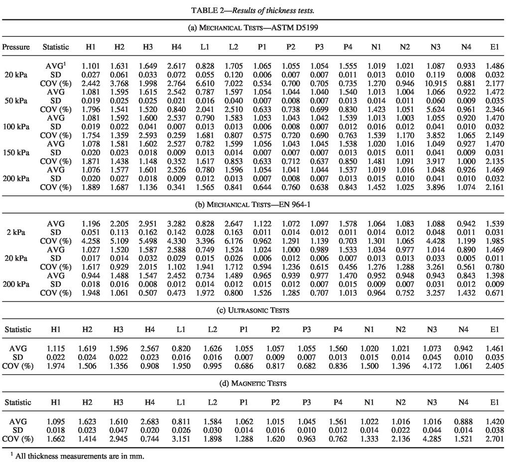
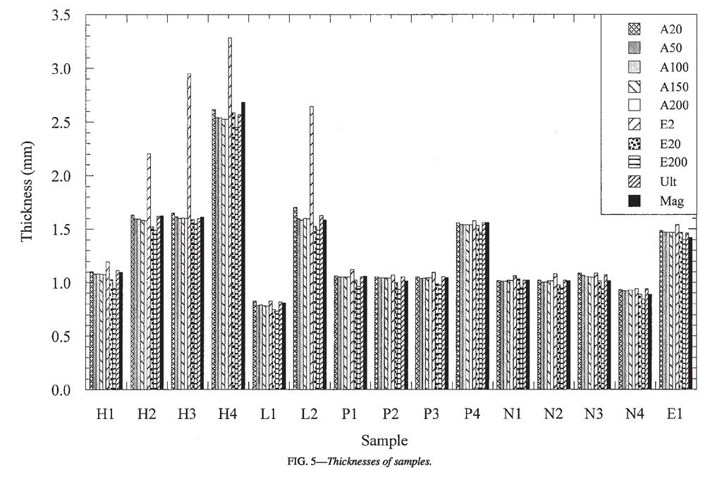
6 variations less than 0.3% for all the samples. It would be possible to establish the velocity for a geomembrane using substantially less measurements, as the variation in the velocities is small. In the preliminary tests, the thicknesses of geomembranes and the travel time of P-waves were used to determine the P-wave velocities. The thickness measurements were made using a mechanical thickness gage under a pressure that represented the pressure applied by the ultrasonic transducer and the attached load on a specimen. This pressure (19 kpa) was generally insufficient to obtain representative measurements, particularly for rigid geomembranes, and extra pressure was applied manually. The specimens were pressed against the flat measurement surface around the loading tip, and a measurement was recorded when the value indicated by the dial gage stabilized under the pressing action. It is believed that representative thickness measurements were obtained this way. The magnetic tests were conducted using a commercially available Hall Effect thickness gage (Fig. 4c). The setup consists of a cylindrical probe and a spherical target with a diameter of 5 mm and a mass of g. Thicknesses can be determined with a resolution of mm using this setup. This particular setup is commonly used for taking thickness measurements of hard-to-reach locations, such as tight corners and grooved areas. For example, in determining the thickness of molded plastic bottles, the target ball is dropped in the bottle and the measurement is done by dragging the ball to the desired measurement location with the probe. In the tests for this study, the specimen was held above the probe at the center, and the target ball was dropped on the specimen to conduct the measurement. The central axis through the ball and the probe needs to be orthogonal to the specimen to obtain representative measurements of thickness. This setup is moderate in size and mobile, which allows for testing both in the laboratory and in the field. However, unlike the ultrasonic setup, access to both sides of a geomembrane is required. Thickness Tests The first set of tests was conducted on 30 specimens cut from the 15 geomembrane samples presented in Table 1. A total of 10 thickness measurements was obtained on each specimen using the mechanical (5 pressure levels for ASTM, 3 pressure levels for European), ultrasonic, and magnetic test setups. The initial set of tests allowed for determination of the thickness of geomembranes and also comparison of the results obtained using the different measurement techniques. A second set of tests was conducted on a single specimen of all 15 geomembrane samples by obtaining 30 measurements on the same location on the specimen, using the 10 different test methods (8 mechanical, 1 ultrasonic, 1 magnetic). These tests were used to determine the repeatability of thickness measurements. Overall, a total of 9000 thickness measurements were made for this test program. Results and Discussion Initially, the thicknesses of the geomembranes determined using the mechanical, ultrasonic, and magnetic methods are presented. Comparisons of the measurements obtained by the different methods are presented subsequently. This is followed by presentation of the repeatability measurements. Then comments about general use and practicality of the methods are provided. Geomembrane Thicknesses The thickness measurements obtained by mechanical, ultrasonic, and magnetic methods are presented in Table 2. The measurements were obtained on 30 specimens of each geomembrane sample, and the average of the 30 thickness measurements (AVG), the corresponding standard deviations (SD), and the coefficient of variations (COV) are presented in the table. The results are also presented in Fig. 5. The thickness of the samples generally decreased with increasing pressures in the mechanical tests. This decrease was particularly pronounced between 20 kpa and 50 kpa in ASTM tests, and between 2 kpa and 20 kpa in EN tests. The amount of decrease was less at the higher pressures for both methods. Also, the decrease was more for the polyethylene samples compared to the other geomembranes. Significantly lower thicknesses were measured at higher pressures and using the nondestructive test methods (Table 2, Fig. 5). The standard deviations for rigid geomembranes are higher than the standard deviations for flexible geomembranes (Table 2). This is particularly noticeable for mechanical measurements (both ASTM and EN) obtained at low pressures. The standard deviations and the differences in standard deviations
7 between rigid and flexible geomembranes decrease at high pressures. The coefficient of variations also decreases at high pressures. The standard deviations and coefficient of variations are generally low for the ultrasonic and the magnetic measurements. Comparison of Methods Comparisons were made to determine whether the thicknesses measured using the various methods were statistically similar. The analysis of variance procedures (ANOVA) and Tukey analysis were used (Mendenhall and Sincich 1995; Milliken and Johnson 1984). Initially, two-way ANOVA analysis was used to compare all 10 measurement procedures at a 95% significance level. The two-way analysis allowed for the determination of the measurement method and geomembrane type effects on the measured thicknesses. This analysis indicated that there were differences in the thickness measurements. The Tukey analysis was used to identify the statistically dissimilar data. The Tukey analysis consisted of a pairwise comparison of all of the measurement procedures for all of the geomembranes. The results of this analysis are presented in Table 3. Table 3 includes 45 comparisons for 15 geomembrane types (675 cells) that consist of the comparisons within the mechanical measurement methods, and between the mechanical, ultrasonic, and magnetic methods. The notation A represents methods that provide significantly different values for thickness, and the notation B represents methods that provide similar values for thickness. The comparisons are summarized for each column representing all comparisons for a single geomembrane type, as well as for each row representing a single comparison for all geomembrane types (Table 3). A complete summary is provided at the lower right corner of the table for all geomembrane types and all comparisons. The data in Table 3 indicate that 81% of the comparisons are statistically different and 19% of the comparisons are statistically similar. Overall, the number of methods that provide similar results is low. The factors in the determination of similarity are the thickness values, and also the standard deviations and coefficient of variations for individual test methods. High differences in thickness values and/or low standard deviations and coefficient of variations result in significant differences between methods (Table 2, Table 3). The highest similarity exists within the ASTM method. The thicknesses obtained using 150 kpa and 200 kpa pressures are similar for all geomembrane types. This is followed by 50 and 100 kpa measurements that are similar for 12 types of geomembranes. The comparisons for kpa, kpa, kpa, and kpa are similar for 10 types of geomembranes. The thicknesses determined at the low ASTM pressure (20 kpa) are generally not similar to the thicknesses determined at higher pressures. There are no similarities within the measurements made using the European standard. Also, there are no similarities between the measurements obtained at the same pressure levels (20 kpa and 200 kpa) using the ASTM and EN methods. The values obtained using the European standard were lower than the thicknesses determined using the ASTM method for both pressure levels (20 kpa and 200 kpa). These values were also lower than the measurements obtained using the ultrasonic and magnetic methods (Table 2). While the similarities for flexible geomembranes are somewhat higher than the similarities for rigid geomembranes, overall, the number of methods that provide similar data for flexible geomembranes is not high. For flexible geomembranes, 60% to 91% of the comparisons are significantly different (Table 3). Repeatability of Measurements The results of the repeatability tests are presented in Table 4. These tests consisted of 30 repetitions of the mechanical, ultrasonic, and magnetic tests on a single specimen of each geomembrane sample. The average of the 30 thickness measurements (AVG), the corresponding standard deviations (SD), and the coefficient of variations (COV) are presented in the table. It was observed that the coefficient of variations was less than 1%, with the majority of values less than 0.5%. The COVs were somewhat higher at low mechanical pressures, compared with the high pressures. This is especially true for the rigid geomembranes such as polyethylene. The highest variations were observed for the magnetic measurements. Holding the specimen perfectly orthogonal to the small
8

9 probe tip and maintaining the 90 angle during the placement of the ball, and then during the measurement, is difficult. It is believed that this caused the slightly higher variations in these measurements. Nevertheless, the repeatability of all of the test methods is good, and there are no significant differences between the methods based on quality of repeatability. Critique of Thickness Measurement Methods Several qualitative observations were made during the thickness measurements that are related to the practical use of the various methods. Also, there are inherent differences between the test methods that need to be discussed further. Problems existed both at the low and high pressure levels for mechanical tests. Mechanical measurements are based on the application of a certain pressure through a specific loading tip. It is difficult to identify the optimum combination of load and loading tip that would work for both flexible and rigid geomembranes. At low pressure levels, it was observed that the pressure applied to the specimens was not sufficient to flatten the specimens and obtain good contact between the loading tip, specimen, and the base of the thickness gage, particularly for rigid geomembranes. On the other hand, an imprint of the loading tip was left after the tip was lifted from the specimens at high pressure levels, particularly with European standard measurements. While the deformation of the specimens was not permanent, this indicated that the specimens were compressed during the measurements, leading to unrepresen tatively low values for thicknesses. In addition, the thicknesses obtained using the EN method were significantly lower than the values obtained using the ASTM method at the same pressure levels (20 kpa and 200 kpa). In fact, the 20 kpa EN measurements were generally lower than the ASTM measurements at higher pressures (Table 2). At the same pressure levels (20 kpa and 200 kpa), a larger area on a geomembrane was subjected to the applied stress in the EN method, compared with the ASTM method.
10 The larger contact area for vertical stress caused greater deformation at the center of the test material. An imprint of the EN probe tip was left on the geomembranes after a measurement using 20 kpa or 200 kpa pressure was made. Such excessive deformation was not observed with the ASTM method. It is believed that the most reliable measurements can be obtained by the nondestructive test methods. The ultrasonic method is based on the transmission of high frequency mechanical waves through a test material. The wave transmission is affected only by the thickness of the test material (Fig. 2). The magnetic method is based on the measurement of the changes in a magnetic field due to the placement of a test material in the field. The thickness of the material causes the changes in the magnetic field (Fig. 3). These methods are not sensitive to the type of the geomembranes (flexible or rigid), and they do not produce any effects on the specimens. In addition, data acquisition procedures are simpler for the nondestructive methods. Data can be stored and analyzed in both the ultrasonic and magnetic gages, and also the stored data can be easily transferred to a computer for further analysis. Warnings can be set

11 up in data acquisition systems that would alert the operator to the presence of out-of-range data during measurements. However, it must be noted that there were shortcomings in the nondestructive procedures used for this study. The magnetic setup used for this analysis is made for testing hard-to-reach locations of different sized and shaped materials. While it allows for testing such locations, it is difficult to maintain the optimum placement of the sheet materials tested in this study in this particular setup. There were problems with holding the specimen at 90 angle during a thickness measurement. A different setup can be used to obtain better measurements that minimizes the effects of operator handling. The preliminary ultrasonic tests can be improved by determining the velocity of the test materials using calibration sheets or blocks with known thicknesses. Geomembrane manufacturers can produce calibration blocks/sheets with known thicknesses for determination of velocities. Calibration blocks are used commonly in ultrasonic testing of metals and other materials (McIntire 1991).
 is based on the evaluation criteria presented in Table 5.")
12 Performance Evaluation of Test Methods The effectiveness of the test methods are evaluated using various criteria presented throughout the paper. A summary of these criteria is presented in Table 5. The overall performance ranking of the methods (Table 6) is based on the evaluation criteria presented in Table 5. The ranking is determined by counting the number of high, medium, and low scores given to each test procedure. The results provided three rankings: excellent that indicates the most effective test method resulting in most representative measurements, good indicating reasonably representative measurements, and poor that indicates essentially unrepresentative mea-
13 surements. In addition to the ranking, comments about the measurement techniques are also presented in Table 6. The lowest pressures for both ASTM and EN methods received poor ranking, as it was observed that artificially high thickness measurements were obtained using these methods. This was particularly noticeable for rigid geomembranes. The 20 kpa and 200 kpa pressures for EN measurements also received poor ratings, as it is believed that unrepresentative low thickness values were obtained at these pressures. The combination of the large loading tip and the applied stresses compressed the specimens excessively, leading to artificially low thickness values. The ASTM tests at 50 kpa to 200 kpa pressures received good ratings. It is believed that reasonably representative and comparable measurements were obtained at these pressures (Table 3). The mechanical measurements received low scores for the high dependency on the applied pressure, the requirement for access to two sides of a specimen, the need for coupon specimens for measurements, and the large size of the test setup required to apply high pressures. The nondestructive measurements are fast, easy, and provide as high resolution and repeatability as the mechanical measurements. Additionally, the nondestructive methods do not require application of pressure or produce any effects on test materials. The magnetic method was ranked good, producing reasonably representative measurements. The main shortcoming of the setup used for the study was related to maintaining the optimum specimen position during a measurement. Also, low scores were given for access required to two sides of a specimen and the requirement for mainly coupon specimen type. Finally, the ultrasonic test method was ranked excellent, as it is believed that the most representative measurements can be obtained with this method. This is the most versatile method with several advantages: access required only to the top surface of the test material, tests conducted on coupons or whole sheets, and small, portable test equipment. As discussed previously, the effectiveness of the method can be improved for the determination of the velocity of the test materials. Thickness measurements obtained under pressure can be representative of field conditions. Expected working pressures can be
14 used to predict field behavior, as it was demonstrated that pressure affected thicknesses significantly. However, it must be noted that similar measurements were not obtained with the ASTM and EN methods at the same pressures (20 kpa and 200 kpa). Contact area affected the measurements obtained, in addition to the magnitude of the applied stresses. While, due to some similarity between the thicknesses obtained at various pressure levels, the ASTM method was deemed more effective than the EN method, whether the contact area and load effectively simulate field conditions is not known. This analysis was beyond the scope of this study. Mechanical tests are best suited for pressure application. However, it might be possible to use the nondestructive tests with pressure application as well. Weights can be added over the ultrasonic transducer to simulate varying pressures. This would not be very plausible with the existing magnetic test setup. Summary and Conclusions Tests were conducted to determine the thickness of smooth geomembranes using three methods: mechanical (using ASTM and European standards), ultrasonic, and magnetic methods. The mechanical method is the standard procedure used for determining thickness of geomembranes. The ultrasonic and magnetic methods are not used commonly for geomembranes, however, they were adapted for the testing program. Tests were conducted on 15 geomembranes representing five types of polymers (HDPE, LLDPE, PVC, PP, and
15 EPDM). The results of the testing program indicated that, in most cases, the thicknesses determined using the various procedures were significantly different. The thickness measurements were affected by the level of pressures applied in mechanical tests. While the low pressures were not sufficient to flatten particularly the rigid geomembranes, the high pressures tended to compress the geomembranes excessively. Both high and low pressures prevented obtaining representative measurements. The measurements obtained using the ASTM method were more reliable than the measurements obtained with the European method. The 50 kpa to 200 kpa pressure range can be used with the ASTM standard tests to obtain reasonably representative measurements. It is believed that the most reliable measurements can be obtained with the nondestructive methods (ultrasonic and magnetic). These techniques are sensitive only to the thickness of the materials (due to the nature of the test methods), and they work equally well for rigid and flexible geomembranes. Of the two methods, ultrasonic testing is better due to several advantages: it allows for testing from the top surface of geomembranes in the laboratory or in the field, and it can be used on either coupons of geomembranes or on whole sheets. Both methods can be improved to work better for geomembranes. Acknowledgment Financial support for this study was provided by the National Science Foundation (NSF Grant No: CMS ). Materials were supplied by various manufacturers including Serrot-National Co., GSE Lining Technology Inc., HPG International Inc., Firestone Inc., and JPS Elastomerics Corp. References ASTM, 1998, Standard Test Method for Measuring Nominal Thickness of Geotextiles and Geomembranes, ASTM Standard No. D , Annual Book of ASTM Standards. Bray, D. E. and McBride, D., Eds., 1992, Nondestructive Testing Techniques, Wiley & Sons Inc., New York, NY. CEN, 1995, Geotextiles and Geotextile-Related Products Determination of Thickness at a Specified Pressure Part 1: Single Layers, CEN Standard No. EN (ISO 9863), European Standards. Daniel, D. E. and Koerner, R. M., 1995, Waste Containment Facilities Guidance for Construction Quality Assurance and Quality Control of Liner and Cover Systems, ASCE, Reston, VA. Giroud, J. P., Beech, J. F., and Soderman, K. L., 1994, Yield of Scratched Geomembranes, Geotextiles and Geomembranes, Elsevier, London, UK, Vol. 13, pp Koerner, R. M., 1997, Designing with Geosynthetics, Prentice-Hall, Upper Saddle River, NJ. Park, J. K., Sakti, J. P., and Hoopes, J. A., 1995, Effectiveness of Geomembranes as Barriers for Organic Compounds, Proceedings of Geosynthetics 95 Conference, IFAI, St. Paul, MN, pp McIntire, P., 1991, Nondestructive Testing Handbook, Volume Seven, Ultrasonic Testing, American Society for Nondestructive Testing, Columbus, OH. Mendenhall, W. and Sincich, T., 1995, Statistics for Engineering and the Sciences, Prentice Hall, Upper Saddle River, NJ. Milliken, G. A. and Johnson, D. E., 1984, Analysis of Messy Data, Volume I: Designed Experiments, Lifetime Learning Publications, Belmont, CA. Steffen, H. and Asmus, D. B., 1993, Geomembrane Sealing of a Waste Disposal Area, Mechernich/Euskirchen, Germany, Geosynthetics Case Histories, G. P. Raymond and J. P. Giroud, Eds., BiTech Publishers Ltd., Canada, pp Sungur, S., 1999, Evaluation of Geomembranes Using Ultrasonic Pulse-Echo Technique, M.S. Thesis, Department of Civil and Environmental Engineering, Wayne State University, Detroit, MI. Yesiller, N. and Sungur, S., 2001, Evaluation of Geomembranes Using an Ultrasonic Method, Geotechnical Testing Journal, Vol. 24, No. 3, pp
16
17
Nazli Yesiller ~, James L. Hanson 2, and Mumtaz A. Usmen 3
 Ultrasonic Assessment of Stabilized Soils Nazli Yesiller ~, James L. Hanson 2, and Mumtaz A. Usmen 3 Abstract The feasibility of using ultrasonic testing, in particular P-wave velocities, to evaluate stabilized
Detection of Concrete Damage Using Ultrasonic Pulse Velocity Method
 Indian Society for Non-Destructive Testing Hyderabad Chapter Proc. National Seminar on Non-Destructive Evaluation Dec. 7-9, 2006, Hyderabad Detection of Concrete Damage Using Ultrasonic Pulse Velocity
Ultrasonic Monitoring of Corrosion with Permanently Installed Sensors (PIMS)
") Ultrasonic Monitoring of Corrosion with Permanently Installed Sensors (PIMS) Frederic Cegla Abstract Ultrasonic wall thickness monitoring using permanently installed sensors has become a tool to monitor
Ultrasonic Monitoring of Corrosion with Permanently Installed Sensors (PIMS) Frederic Cegla Abstract Ultrasonic wall thickness monitoring using permanently installed sensors has become a tool to monitor
Effect of Geomembrane Texturing on GCL - Geomembrane Interface Shear Strength
 McCartney, J.S., Zornberg, J.G., and Swan, R.H. (2005). Effect of Geomembrane Texturing on GCL-Geomembrane Interface Shear Strength. Waste Containment and Remediation. ASCE Geotechnical Special Publication
Reading assignment. Nondestructive evaluation (NDE) Nondestructive testing (NDT) Penetrant. Conventional NDE mthods. Topic 7
 Nondestructive testing (NDT) Penetrant. Conventional NDE mthods. Topic 7") Reading assignment Nondestructive evaluation (NDE) Topic 7 Notes on Nondestructive Evaluation in the course website. Sec. 8.2, 8.3 and 8.4, William Callister, Materials Science and Engineering, 6 th Ed.
Reading assignment Nondestructive evaluation (NDE) Topic 7 Notes on Nondestructive Evaluation in the course website. Sec. 8.2, 8.3 and 8.4, William Callister, Materials Science and Engineering, 6 th Ed.
SPE MS. Copyright 2015, Society of Petroleum Engineers
 SPE-177570-MS EVO Series 1.0 - Latest Generation of UT Crack and Corrosion Tools For High Speed Pipeline Inspection T. Hennig, NDT Global Corporate Ltd.; G. Lokwani, NDT Middle East Copyright 2015, Society
STRESS CHARACTERIZATION BY LOCAL MAGNETIC MEASUREMENTS
 STRESS CHARACTERIZATION BY LOCAL MAGNETIC MEASUREMENTS P.lvanov, Y.Sun, L.Udpa, S.S.Udpa and W.Lord Department of Electrical and Computer Engineering Iowa State University, Ames, Iowa INTRODUCTION The
NONDESTRUCTIVE EVALUATION (NDE) METHODS FOR QUALITY ASSURANCE OF EPOXY INJECTION CRACK REPAIRS
 METHODS FOR QUALITY ASSURANCE OF EPOXY INJECTION CRACK REPAIRS") NONDESTRUCTIVE EVALUATION (NDE) METHODS FOR QUALITY ASSURANCE OF EPOXY INJECTION CRACK REPAIRS by Yajai Promboon, Ph.D., Larry D. Olson, P.E. Olson Engineering, Inc. and John Lund, P.E. Martin/Martin,
NONDESTRUCTIVE EVALUATION (NDE) METHODS FOR QUALITY ASSURANCE OF EPOXY INJECTION CRACK REPAIRS by Yajai Promboon, Ph.D., Larry D. Olson, P.E. Olson Engineering, Inc. and John Lund, P.E. Martin/Martin,
EVALUATING THE INTEGRITY OF ADHESIVE BONDS BY THE MEASUREMENT OF ACOUSTIC PROPERTIES UNDER STRESSES
 EVALUATING THE INTEGRITY OF ADHESIVE BONDS BY THE MEASUREMENT OF ACOUSTIC PROPERTIES UNDER STRESSES V. Jagasivamani Analytical Services & Materials Inc. Hampton, V A 23666 Alphonso C. Smith Hampton University
Introduction. 1. Cause of earing
 A highly accurate acoustic velocity measurement system using an Electro-Magnetic Acoustic Transducer (EMAT) has been developed in order to evaluate the texture of aluminum plates. A good correlation between
Drainage geocomposite workshop
 Drainage geocomposite workshop By Gregory N. Richardson, Sam R. Allen, C. Joel Sprague A number of recent designer s columns have focused on the design of drainage geocomposites (Richardson and Zhao, 998),
Smooth Liner THE MATERIAL OF CHOICE FOR CONTAINMENT APPLICATIONS
 Smooth Liner THE MATERIAL OF CHOICE FOR CONTAINMENT APPLICATIONS 1 The Plastics Experts. AGRU geosynthetic liners are manufactured with only the highest-grade polyethylene resins using the calendared flat-die
Application of ultrasonic testing to steel-concrete composite structures
 More Info at Open Access Database www.ndt.net/?id=18338 Application of ultrasonic testing to steel-concrete composite structures Arisa YANAGIHARA 1, Hiroaki HATANAKA 2, Minoru TAGAMI 2, Katsuya TODA 3,
1. SCOPE 2. REFERENCED DOCUMENTS
 Illinois Test Procedure 405 Effective Date: January 1, 2016 Determining the Fracture Potential of Asphalt Mixtures Using the Illinois Flexibility Index Test (I-FIT) 1. SCOPE 1.1. This test method covers
UNIFIED FACILITIES GUIDE SPECIFICATIONS
 USACE / NAVFAC / AFCEC / NASA UFGS-02 66 10 (February 2010) ----------------------------- Preparing Activity: USACE Superseding UGGS-02 66 10 (April 2006) UNIFIED FACILITIES GUIDE SPECIFICATIONS References
GRI GM30* Test Methods, Test Properties and Testing Frequency for Coated Tape Polyethylene (cpe) Barriers
 Barriers") Geosynthetic Institute 475 Kedron Avenue Folsom, PA 19033-1208 USA TEL (610) 522-8440 FAX (610) 522-8441 GEI GRI GSI GAI GCI GII Original: May 25, 2016 GRI GM30* Standard Specification for Test Methods,
Geosynthetic Institute 475 Kedron Avenue Folsom, PA 19033-1208 USA TEL (610) 522-8440 FAX (610) 522-8441 GEI GRI GSI GAI GCI GII Original: May 25, 2016 GRI GM30* Standard Specification for Test Methods,
The strange effect of increasing temperature in accelerated ageing of HDPE geomembranes immersed in liquids
 9 th International Conference on Geosynthetics, Brazil, The strange effect of increasing temperature in accelerated ageing of HDPE geomembranes immersed in liquids R. Kerry Rowe Geoengineering Centre at
Advanced Inspection of Steel Elements
 Advanced Inspection of Steel Elements Methods of Inspection Level II inspection in steel elements is made if cracks or potential for cracks or faults is present. Visual Important for detecting degradation
DEVELOPMENT OF A SUCCESSFUL UNTETHERED LEAK DETECTION AND PIPE WALL CONDITION ASSESSMENT TECHNOLOGY FOR LARGE DIAMETER PIPELINES
 DEVELOPMENT OF A SUCCESSFUL UNTETHERED LEAK DETECTION AND PIPE WALL CONDITION ASSESSMENT TECHNOLOGY FOR LARGE DIAMETER PIPELINES Hugh Chapman, General Manager Aqua Environmental ABSTRACT Leak detection
ULTRASONIC MEASUREMENT OF RESIDUAL STRESSES IN WELDED SPECIMENS AND STRUCTURES
 Proceedings of the ASME 2013 Pressure Vessels and Piping Conference PVP2013 July 14-18, 2013, Paris, France PVP2013-97184 ULTRASONIC MEASUREMENT OF RESIDUAL STRESSES IN WELDED SPECIMENS AND STRUCTURES
Experimental Study on Triaxial Geogrid-Reinforced Bases over Weak Subgrade under Cyclic Loading
 : Advances in Analysis, Modeling & Design 128 Experimental Study on Triaxial Geogrid-Reinforced Bases over Weak Subgrade under Cyclic Loading Yu Qian 1, Jie Han 2, Sanat K. Pokharel 3, and Robert L. Parsons
Department of Mechanical Engineering, College of Industrial Technology, Nihon University, 1-2-1, Izumi, Narashino, Chiba , Japan.
 NEW CONCEPT OF AE STANDARD: JIS Z 2342-2002 METHOD FOR ACOUSTIC EMISSION TESTING OF PRESSURE VESSELS DURING PRESSURE TESTS AND CLASSIFICATION OF TEST RESULTS Y. MORI 1, M. SHIWA 2, M. NAKANO 3 AND K. IWAI
Detection of hidden defects in thin steel plates using GMR sensor arrays
 11th European Conference on Non-Destructive Testing (ECNDT 2014), October 6-10, 2014, Prague, Czech Republic Detection of hidden defects in thin steel plates using GMR sensor arrays More Info at Open Access
Evaluation of the Orientation of 90 and 180 Reinforcing Bar Hooks in Wide Members
 Research Note Research Note RN-2009-2 Evaluation of the Orientation of 90 and 180 Reinforcing Bar Hooks in Wide Members Introduction Longitudinal reinforcing steel bars in flexural members are often developed
Utilization of Combined NDT in the Concrete Strength Evaluation of Core Specimen from Existing Building
 Utilization of Combined NDT in the Concrete Strength Evaluation of Core Specimen from Existing Building Hemraj R Kumavat 1, Vikram J Patel 2 Ganesh V Tapkire 3, Rajendra D Patil 4 Assistant Professor,
Soundness Evaluation of Underwater Concrete Structures based on the Combination of Rebound Hardness and Ultrasonic Pulse Velocity Methods
 Soundness Evaluation of Underwater Concrete Structures based on the Combination of Rebound Hardness and Ultrasonic Pulse Velocity Methods Sang-Hun Han 1) Eun-Seok Shin 2) Gi-Chun Cha 2) and Seunghee Park
SENSOR TIP OPTIMIZATION FOR A THERMAL ANEMOMETER FOR DETERMINING CONVECTION INTENSITY IN QUENCH BATHS
 21st ASM Heat Treating Society Conference Proceedings, 5-8 November 2001, Indianapolis, IN, ASM International, Copyright 2001 SENSOR TIP OPTIMIZATION FOR A THERMAL ANEMOMETER FOR DETERMINING CONVECTION
ISO INTERNATIONAL STANDARD. Non-destructive testing of welds Ultrasonic testing Techniques, testing levels, and assessment
 INTERNATIONAL STANDARD ISO 17640 Second edition 2010-12-15 Non-destructive testing of welds Ultrasonic testing Techniques, testing levels, and assessment Contrôle non destructif des assemblages soudés
DETERMINING THE STRENGTH OF SOLID BURNT BRICKS IN HISTORICAL STRUCTURES
 9th International Conference on NDT of Art, Jerusalem Israel, - May 8 For more papers of this publication click: www.ndt.net/search/docs.php?mainsource=6 DETERMINING THE STRENGTH OF SOLID BURNT BRICKS
Non-destructive testing of welds Ultrasonic testing Techniques, testing levels, and assessment
 Provläsningsexemplar / Preview INTERNATIONAL STANDARD ISO 17640 Third edition 2017-10 Non-destructive testing of welds Ultrasonic testing Techniques, testing levels, and assessment Essais non destructifs
Angle Cleat Base Connections
 Missouri University of Science and Technology Scholars' Mine International Specialty Conference on Cold- Formed Steel Structures (2010) - 20th International Specialty Conference on Cold-Formed Steel Structures
ACTION LEAKAGE RATE GUIDELINE. Prepared by:
 ACTION LEAKAGE RATE GUIDELINE Prepared by: INDUSTRIAL WASTE AND WASTEWATER BRANCH AIR AND WATER APPROVALS DIVISION ALBERTA ENVIRONMENTAL PROTECTION MAY 1996 ACTION LEAKAGE RATE GUIDELINE INDUSTRIAL WASTE
ELASTIC ANISOTROPY IN PARTICLE/FIBER REINFORCED ALUMINUM METAL MATRIX COMPOSITES. B.Grelsson and K.Salama
 ELASTIC ANISOTROPY IN PARTICLE/FIBER REINFORCED ALUMINUM METAL MATRIX COMPOSITES B.Grelsson and K.Salama Department of Mechanical Engineering University of Houston Houston, TX 7724 INTRODUCTION Metal matrix
GCL ALTERNATIVE LINER AND CRITICAL SLOPE STABILITY UNIQUE CASE HISTORY INVOLVING ENCAPSULATED DESIGN APPROACH
 GCL ALTERNATIVE LINER AND CRITICAL SLOPE STABILITY UNIQUE CASE HISTORY INVOLVING ENCAPSULATED DESIGN APPROACH R. THIEL* AND R. ERICKSON** * Thiel Engineering, P.O. Box 00, Oregon House, California, 9596,
ISO Non-destructive testing of welds Ultrasonic testing Use of automated phased array technology
 INTERNATIONAL STANDARD ISO 13588 First edition 2012-10-01 Non-destructive testing of welds Ultrasonic testing Use of automated phased array technology Contrôle non destructif des assemblages soudés Contrôle
Determining in-place concrete strengths is particularly
 Core Testing Requirements for Seismic Evaluation of Existing Structures Evaluation practices for nonseismic structures can be adapted by Halil Sezen, Chuck Hookham, Kenneth J. Elwood, F. Michael Bartlett,
Technical Notes 39A - Testing for Engineered Brick Masonry - Determination of Allowable Design Stresses [July/Aug. 1981] (Reissued December 1987)
![Technical Notes 39A - Testing for Engineered Brick Masonry - Determination of Allowable Design Stresses [July/Aug. 1981] (Reissued December 1987)](/thumbs/75/72632512.jpg "Technical Notes 39A - Testing for Engineered Brick Masonry - Determination of Allowable Design Stresses [July/Aug. 1981] (Reissued December 1987)") Technical Notes 39A - Testing for Engineered Brick Masonry - Determination of Allowable Design Stresses [July/Aug. 1981] (Reissued December 1987) INTRODUCTION Prior to the development of a rational design
Technical Notes 39A - Testing for Engineered Brick Masonry - Determination of Allowable Design Stresses [July/Aug. 1981] (Reissued December 1987) INTRODUCTION Prior to the development of a rational design
NOVEL METHODS FOR CRACK DETECTION IN GREEN AND SINTERED PARTS
 NOVEL METHODS FOR CRACK DETECTION IN GREEN AND SINTERED PARTS Yun Zhu, Eric T. Hauck, and Joseph L. Rose 212 Earth & Engineering Science Building Department of Engineering Science and Mechanics The Pennsylvania
DEVELOPMENT OF A SUCCESSFUL INTERNAL LEAK DETECTION AND PIPELINE CONDITION ASSESSMENT TECHNOLOGY FOR LARGE DIAMETER PIPES.
 DEVELOPMENT OF A SUCCESSFUL INTERNAL LEAK DETECTION AND PIPELINE CONDITION ASSESSMENT TECHNOLOGY FOR LARGE DIAMETER PIPES Paper Presented by: Hugh Chapman Author: Hugh Chapman, General Manager, Aqua Environmental
HMA GROUP AUSTRALIA - NEW ZEALAND - INDONESIA - SOUTH AFRICA SINCE 1966
 SINCE 1966 Introduction Geotechnical Systems Australia (GSA) was founded in March 1987 to design, manufacture and distribute geotechnical instrumentation for the geotechnical and mining industries. Now
GRI-GM22 GM22 Specification Reinforced Polyethylene Geomembranes for Exposed Temporary Applications
 GRI-GM22 GM22 Specification Reinforced Polyethylene Geomembranes for Exposed Temporary Applications targeted lifetime is 5-105 years 20, 12, 8 mil (0.50, 0.30, 0.20 mm) thickness classes silent on method
Lateral drainage design update Part 2
 Lateral drainage design update Part 2 By Gregory N. Richardson, P.E., Ph.D., J.P. Giroud, P.E., Ph.D., and Aigen Zhao, P.E., Ph.D. Part 1 of this series established the need to design lateral drainage
INTRODUCTION TO ULTRASONIC IN-LINE INSPECTION OF CRA PIPELINES. Herbert Willems, Gerhard Kopp NDT Global, Germany
 INTRODUCTION TO ULTRASONIC IN-LINE INSPECTION OF CRA PIPELINES Herbert Willems, Gerhard Kopp NDT Global, Germany ABSTRACT Pipelines manufactured from corrosion-resistant alloys (CRA) are becoming more
Specifications for Concrete Embedment Liner
 Specifications for Concrete Embedment Liner Part 1: GENERAL 1.01 SECTION INCLUDES A. Specifications and guidelines for MANUFACTURING high-density polyethylene embedment liners. 1.02 REFERENCES A. American
CONTINUOUS FLIGHT AUGER (CFA) PILES QC/QA PROCEDURES. Preferred QC/QA Procedures
 PILES QC/QA PROCEDURES. Preferred QC/QA Procedures") Preferred QC/QA Procedures The Federal Highway Administration (FHWA) has provided QC/QA guidance for this technology as noted below. The reference document also contains information about construction
Preferred QC/QA Procedures The Federal Highway Administration (FHWA) has provided QC/QA guidance for this technology as noted below. The reference document also contains information about construction
AN EXPERIMENTAL STUDY ON THE CREEP BEHAVIOR OF EXPANDED POLYSTYRENE (EPS) GEOFOAM UNDER SUSTAINED LOAD
 GEOFOAM UNDER SUSTAINED LOAD") line 2. 3 4 5 AN EXPERIMENTAL STUDY ON THE CREEP BEHAVIOR OF EXPANDED POLYSTYRENE (EPS) GEOFOAM UNDER SUSTAINED LOAD 2 Mohamed A. Meguid, Mohamed Kamili and Tarik A. Youssef 2 Department of Civil Engineering
line 2. 3 4 5 AN EXPERIMENTAL STUDY ON THE CREEP BEHAVIOR OF EXPANDED POLYSTYRENE (EPS) GEOFOAM UNDER SUSTAINED LOAD 2 Mohamed A. Meguid, Mohamed Kamili and Tarik A. Youssef 2 Department of Civil Engineering
For NGTL to file calculation of operating condition on pull back stress analysis.
 NOVA Gas Transmission Ltd. Exhibit No. B85 National Energy Board Hearing Order GH-001-2014 Undertaking U-10 Submitted November 25, 2014 Response to Undertaking given by Mr. Trout to Chairman Vergette at
Fatigue Damage Evaluation of SUS304 Steel Using Magnetism Change in Fatigue Process
 OS3-3-1 ATEM'07, JSME-MMD, Sep. 12-14, 2007 Fatigue Damage Evaluation of SUS304 Steel Using Magnetism Change in Fatigue Process Daiki Shiozawa 1, Yoshikazu Nakai 1, Yoshitaka Eijima 2 1. Department of
Acoustic tomography in relation to 2D ultrasonic velocity and hardness mappings
 Wood Sci Techno1 (2012) 46:551-561 DOI 10.1007/s00226-011-0426-y ORIGINAL Acoustic tomography in relation to 2D ultrasonic velocity and hardness mappings Li Li Xiping Wang Lihai Wang R. Bruce Allison Received:
ELASTIC WAVE PROPAGATION AND SCATTERING IN AUSTENITIC STEEL. F. Waite Fraunhofer-Institute for Nondestructive Testing Saarbriicken, Germany
 ELASTIC WAVE PROPAGATION AND SCATTERING IN AUSTENITIC STEEL S. Klaholz, K. J. Langenberg, P. Baum Dept. Electrical Engineering University of Kassel 34109 Kassel, Germany F. Waite Fraunhofer-Institute for
GRI Standard GC8 * Determination of the Allowable Flow Rate of a Drainage Geocomposite
 Geosynthetic Institute 475 Kedron Avenue Folsom, PA 19033-1208 USA TEL (610) 522-8440 FAX (610) 522-8441 GEI GRI GSI GAI GCI GII Original: April 17, 2001 Rev. 1: January 9, 2013-Editorial GRI Standard
UNIFIED FACILITIES GUIDE SPECIFICATIONS
 USACE / NAVFAC / AFCEC / NASA UFGS-31 05 20 (August 2008) --------------------------- Preparing Activity: USACE Superseding UFGS-31 05 20 (April 2006) UNIFIED FACILITIES GUIDE SPECIFICATIONS References
Portable, semi-automatic device for non-destructive ultrasonic measurement of residual stresses in samples, parts, welded elements and structures
 Portable, semi-automatic device for non-destructive ultrasonic measurement of residual stresses in samples, parts, welded elements and structures UltraMARS - 7 SINTEC www.sintec.ca 1. Introduction The
Available from the American Society for Nondestructive Testing (ASNT) 1711 Arlingate Plaza, P.O. Box 28518, Columbus, OH
 1711 Arlingate Plaza, P.O. Box 28518, Columbus, OH") Designation: OV-STD-NMIUS10-17 Standard Practice for DETECTION OF NON-METALLIC INCLUSIONS IN STEELS WITH HIGH CLEANLINESS DEMANDS SUCH AS CASE- OR THROUGH HARDENING BEARING STEELS BY THE ULTRASONIC METHOD
Designation: OV-STD-NMIUS10-17 Standard Practice for DETECTION OF NON-METALLIC INCLUSIONS IN STEELS WITH HIGH CLEANLINESS DEMANDS SUCH AS CASE- OR THROUGH HARDENING BEARING STEELS BY THE ULTRASONIC METHOD
Response of Metal Roofs to Uniform Static and True Hurricane Wind Loads
 Missouri University of Science and Technology Scholars' Mine International Specialty Conference on Cold- Formed Steel Structures (2008) - 19th International Specialty Conference on Cold-Formed Steel Structures
Chemical Compatibility of Geosynthetic Clay Liners to Aggressive Bauxite Liquor
 Abstract Chemical Compatibility of Geosynthetic Clay Liners to Aggressive Bauxite Liquor Kuo Tian 1 and Craig H. Benson 2 1. Research Scientist, Department of Civil and Environmental Engineering George
FLUXUS F601. Portable, quick and reliable. Clamp-on ultrasonic flow meter. Measure from outside what's flowing inside
 Reliable flow measurement in less than 5 minutes. Wide application range. With long life marathon battery. Portable, quick and reliable FLUXUS F601 Clamp-on ultrasonic flow meter Accurate Flexible Quick
RE-EXAMINATION OF NIST ACOUSTIC EMISSION SENSOR CALIBRATION: Part I Modeling the loading from glass capillary fracture
 RE-EXAMINATION OF NIST ACOUSTIC EMISSION SENSOR CALIBRATION: Part I Modeling the loading from glass capillary fracture Abstract BRIAN BURKS Mechanical and Materials Engineering Department, University of
ARC RECIPROCATING WEAR AT HIGH TEMPERATURE
 ARC RECIPROCATING WEAR AT HIGH TEMPERATURE Prepared by Duanjie Li, PhD 6 Morgan, Ste156, Irvine CA 92618 P: 949.461.9292 F: 949.461.9232 nanovea.com Today's standard for tomorrow's materials. 2016 NANOVEA
Behaviour of deviated CFRP-Strips
 Fourth International Conference on FRP Composites in Civil Engineering (CICE2008) 22-24July 2008, Zurich, Switzerland Behaviour of deviated CFRP-Strips M. Hwash 1, J. Knippers 1 & F. Saad 2 1 Institut
EMAT with Pulsed electromagnet for high temperature
 EMAT with Pulsed electromagnet for high temperature Francisco Hernandez-Valle Steve Essex & Steve Dixon Ultrasonics Group BINDT, September 2009 OVERVIEW OF TALK 1 Background 4 Experimental work 2 High
Monitoring Of Adhesive Cure Process and Following Evaluation of Adhesive Joint Structure by Acoustic Techniques
 ECNDT 006 - We... Monitoring Of Adhesive Cure Process and Following Evaluation of Adhesive Joint Structure by Acoustic Techniques Elena Yu. MAEVA, Ina SEVIARYNA, Gilbert B. CHAPMAN, Fedar M. SEVERIN University
REAL-TIME CONCENTRATION AND GRAIN SIZE MEASUREMENT OF SUSPENDED SEDIMENT USING MULTI-FREQUENCY BACKSCATTERING TECHNIQUES ABSTRACT
 REAL-TIME CONCENTRATION AND GRAIN SIZE MEASUREMENT OF SUSPENDED SEDIMENT USING MULTI-FREQUENCY BACKSCATTERING TECHNIQUES T. HIES 1, H. H. NGUYEN 2, J. SKRIPALLE 3 1,2 HydroVision Asia Pte Ltd, 1 Cleantech
ALL NEW New Products Guide
 ALL NEW 2011 New Products Guide 2011 CAT-5510.1 Patented Upgrading of load capacity and rigidity on your machine! Comparison of basic static load ratings Comparison of elastic deformation under downward
The Influence of Grain Size of Dissimilar Welding between Carbon Steel and Stainless Steel on Ultrasonic Testing
 International Conference on Test, Measurement and Computational Method (TMCM 2015) The Influence of Grain Size of Dissimilar Welding between Carbon Steel and Stainless Steel on Ultrasonic Testing Kwanruethai
CLASSIFICATION NOTES. Type Approval. Mechanical Joints. used in Piping
 CLASSIFICATION NOTES Type Approval of Mechanical Joints used in Piping Revision 2 : January, 2014 Contents Sections 1. General 2. Scope 3. Documentation 4. Materials 5. Testing Procedure and Requirements
UltraMARS TM 6D. Integrity Testing Laboratory Inc.
 Portable, semi-automatic device for non-destructive ultrasonic measurement of applied and residual stresses in samples, parts, welded elements and structures UltraMARS TM 6D Integrity Testing Laboratory
Evaluation of Tensile Properties of HDPE Geomembranes with Temperature under Exposure to Chemical Solutions
 한국섬유공학회지, 제 50 권제 1 호 2013 년 < 연구논문 > http://dx.doi.org/10.12772/tse.2013.50.061 화학용액에노출시킨 HDPE Geomembranes 의온도에따른인장특성평가 Belas Ahmed Khan 전한용 1 인하대학교대학원섬유공학과, 1 인하대학교나노시스템공학부 (2012. 12. 6. 접수 /2013. 2.
A Validated Discrete Element Modeling Approach for Studying Geogrid-Aggregate Reinforcement Mechanisms
 ASCE 2011 4653 A Validated Discrete Element Modeling Approach for Studying Geogrid-Aggregate Reinforcement Mechanisms Yu Qian 1, Erol Tutumluer 2, M. ASCE, and Hai Huang 3 1 Graduate Research Assistant,
ADHESIVE CURE MONITORING WITH ACOUSTIC METHOD
 ADHESIVE CURE MONITORING WITH ACOUSTIC METHOD I. Severina, E. Maeva Industrial Research Chair In Applied Solid State Physics and Material Characterization, University of Windsor, Windsor, Canada Abstract:
HX Performance Testing
 Nuclear Division HX Performance Testing FSRUG January 26, 2016 1 February 3, 2016 2014 Curtiss-Wright Agenda Why Heat Exchanger Performance Testing (HXPT) is required GL 89-13 Overview Typical HXPT Methodology
LARGE TRIAXIAL TESTS ON FABRIC REINFORCED AND CEMENT MODIFIED MARGINAL SOIL
 IGC 2009, Guntur, INDIA LARGE TRIAXIAL TESTS ON FABRIC REINFORCED AND CEMENT MODIFIED MARGINAL SOIL G.V. Praveen Research Scholar, Faculty, S.R. Engg. College, Warangal, India. V. Ramana Murty Assistant
Nondestructive Testing
 Nondestructive Testing Prof. A.K.M.B. Rashid Department of MME BUET, Dhaka Nondestructive inspections fundamentals Classification of nondestructive inspections Radiographic inspection Magnetic particle
GRI Standard GS-15* Test Methods, Test Properties and Testing Frequency for Geocells Made From High Density Polyethylene (HDPE) Strips
 Strips") Geosynthetic Institute 475 Kedron Avenue Folsom, PA 19033-1208 USA TEL (610) 522-8440 FAX (610) 522-8441 GEI GRI GSI GAI GCI GII GRI Standard GS-15* Revision 1: January 5, 2016 Standard Specification for
Geosynthetic Institute 475 Kedron Avenue Folsom, PA 19033-1208 USA TEL (610) 522-8440 FAX (610) 522-8441 GEI GRI GSI GAI GCI GII GRI Standard GS-15* Revision 1: January 5, 2016 Standard Specification for
Ultrasonic Measurement of Residual Stresses in Welded Railway Bridge
 Ultrasonic Measurement of Residual Stresses in Welded Railway Bridge Y. Kudryavtsev, J. Kleiman and O. Gustcha ABSTRACT The residual stresses have a significant effect on the process of the initiation
DNVGL-CP-0347 Edition May 2016
 CLASS PROGRAMME Approval of manufacturers DNVGL-CP-0347 Edition May 2016 The content of this service document is the subject of intellectual property rights reserved by ("DNV GL"). The user accepts that
E. Section Polymer Modified Cement Waterproofing. K. Section Sub drainage: Foundation perimeter drainage.
 DELTA -DRAIN 6200 Section 07 10 00 Dampproofing and Waterproofing PART 1 GENERAL 1.1 SECTION INCLUDES A. Below grade waterproofing. B. Below grade drainage sheets. C. Plaza deck and planter drainage sheets.
Title. Author(s)KARMAZÍNOVÁ, M.; MELCHER, J.; LÁNÍK, J. Issue Date Doc URL. Type. Note. File Information
KARMAZÍNOVÁ, M.; MELCHER, J.; LÁNÍK, J. Issue Date Doc URL. Type. Note. File Information") Title DIAGNOSTICS OF STEEL ROOF STRUCTURES OF SPORT STADIU Author(s)KARMAZÍNOVÁ, M.; MELCHER, J.; LÁNÍK, J. Issue Date 2013-09-11 Doc URL http://hdl.handle.net/2115/54209 Type proceedings Note The Thirteenth
Title DIAGNOSTICS OF STEEL ROOF STRUCTURES OF SPORT STADIU Author(s)KARMAZÍNOVÁ, M.; MELCHER, J.; LÁNÍK, J. Issue Date 2013-09-11 Doc URL http://hdl.handle.net/2115/54209 Type proceedings Note The Thirteenth
MECHANICAL PROPERTIES OF MATERIALS
 MECHANICAL PROPERTIES OF MATERIALS Stress-Strain Relationships Hardness Effect of Temperature on Properties Fluid Properties Viscoelastic Behavior of Polymers Mechanical Properties in Design and Manufacturing
INDIAN REGISTER OF SHIPPING CLASSIFICATION NOTES. Type Approval of Mechanical Joints used in Piping
 INDIAN REGISTER OF SHIPPING CLASSIFICATION NOTES Type Approval of Mechanical Joints used in Piping January 2017 Page 2 of 16 Changes in JANUARY 2017 Version Type Approval of Mechanical Joints used in Piping
#4 Simplified Vertical Rebound Testing
 I. INTRODUCTION To close the yellow note, click once to select it and then click the box in the upper left corner. To open the note, double click (Mac OS) or right click (Windows) on the note icon. #4
YIELD & TENSILE STRENGTH OF STEEL & ALUMINIUM USING MICROINDENTATION
 YIELD & TENSILE STRENGTH OF STEEL & ALUMINIUM USING MICROINDENTATION Prepared by Duanjie Li, PhD & Pierre Leroux 6 Morgan, Ste156, Irvine CA 9618 P: 949.461.99 F: 949.461.93 nanovea.com Today's standard
Testing and Evaluation of CFS L-headers
 Missouri University of Science and Technology Scholars' Mine International Specialty Conference on Cold- Formed Steel Structures (2008) - 19th International Specialty Conference on Cold-Formed Steel Structures
INTERNAL PRESSURE AND BACKFILL LOAD RESISTANCE CHARACTERISTICS OF POPIT LIFT HOLE PLUGS
 INTERNAL PRESSURE AND BACKFILL LOAD RESISTANCE CHARACTERISTICS OF POPIT LIFT HOLE PLUGS CONCRETE PIPES WITH A MECHNICAL OR ROUGH LIFT HOLE (Note : This report is prepared of information to readers only)
D-1. Addendum to the Construction Quality Assurance Plan
 ONONDAGA LAKE SCA FINAL COVER DESIGN REPORT D-1 Addendum to the Construction Quality Assurance Plan PARSONS P:\Honeywell -SYR\448533 SCA Final Cover Design\09 Reports\9.10 2016 Final Design Submittal\Final
Studies on the Punching Characteristics of Rigid Copper Clad Laminates
 Journal of National Kaohsiung University of Applied Sciences, Vol. 33 (2004), pp. 31-40 Studies on the Punching Characteristics of Rigid Copper Clad Laminates Quang-Cherng Hsu * Abstract In this paper,
Evaluation of HDPE (High Density. Drainage Pipe Manufacturers. Polyethylene) Thermoplastic. NTPEP Committee Work Plan for
 Thermoplastic. NTPEP Committee Work Plan for") NTPEP Committee Work Plan for Evaluation of HDPE (High Density Polyethylene) Thermoplastic Drainage Pipe Manufacturers NTPEP Designation: [HDPE-01-16] National Transportation Product Evaluation Program
NTPEP Committee Work Plan for Evaluation of HDPE (High Density Polyethylene) Thermoplastic Drainage Pipe Manufacturers NTPEP Designation: [HDPE-01-16] National Transportation Product Evaluation Program
stationary and portable hardness testers devices for testing layer thickness scratching resistance coating adhesion strength
 Automation and quality assurance in material testing BAQ stationary and portable hardness testers devices for testing layer thickness abrasion resistance scratching resistance coating adhesion strength
 Designation: D 2122 98 (Reapproved 2004) An American National Standard Standard Test Method for Determining Dimensions of Thermoplastic Pipe and Fittings 1 This standard is issued under the fixed designation
Effective Date: Revision #: 1. Section K: Miscellaneous. Casing Insulators/ Stainless Steel. Polyethylene Encasement.
 K 1 K 2 K 3 K 4 K 5 K 6 K 7 K 8 K 9 Casing Insulators/ Stainless Steel Polyethylene Encasement Manhole Inserts Pipe Saddle Support/ Valve Vaults/ Adjustable Cylindrical Wall Seals & Line Sleeves Metal
Evaluation of Copper Stave Remnant Thickness in Blast Furnace Using Ultrasonic Method
 , pp. 605 610 Evaluation of Copper Stave Remnant Thickness in Blast Furnace Using Ultrasonic Method Sriniwasagan BALAMURUGAN, 1) * Rajendran SHUNMUGASUNDARAM, 1) Mantu PATRA, 2) Sameeran PANI 2) and Monojit
SOME REMARKS ON ULTRASONIC TESTING FOR CAST IRON PARTS
 SOME REMARKS ON ULTRASONIC TESTING FOR CAST IRON PARTS Daniel Vlaicu 1, Luminita Irimescu 2, Delia Cerlincă 2 1 SIDEM, Suceava - vlaicu_daniel92@yahoo.com 2,3 Faculty of Mechanical Engineering, Mechatronics
GRI-GC16 Standard Specification * Test Methods, Required Properties and Testing Frequency for Prefabricated Vertical Drains (PVDs)
") Geosynthetic Institute 475 Kedron Avenue Folsom, PA 19033-1208 USA TEL (610) 522-8440 FAX (610) 522-8441 GEI EI GAI GRI GSI GCI GII Revision 2: July 24, 2017 Revision schedule on pg. 9 GRI-GC16 Standard
Geosynthetic Institute 475 Kedron Avenue Folsom, PA 19033-1208 USA TEL (610) 522-8440 FAX (610) 522-8441 GEI EI GAI GRI GSI GCI GII Revision 2: July 24, 2017 Revision schedule on pg. 9 GRI-GC16 Standard
Advanced Thin Film Geomembrane Technology For Biocell Liners and Covers. D. Martin, P. Eng
 Advanced Thin Film Geomembrane Technology For Biocell Liners and Covers D. Martin, P. Eng Research & Technology Manager, Layfield Geosynthetics and Industrial Fabrics Ltd, 11603 180 st, Edmonton, AB, Canada.
Evaluation of Structural Properties of the Freeze Thaw-Damaged RC Beam Members by Nonlinear Finite-Element Analysis
 4 th International Conference on the Durability of Concrete Structures 24 26 July 214 Purdue University, West Lafayette, IN, USA Evaluation of Structural Properties of the Freeze Thaw-Damaged RC Beam Members
WYATT Orifice flow PrOducTs
 WYATT Orifice Differential producers, specifically orifice plates, are used in flow measurement due to their simplicity, ease of installation, tolerance to extreme atmospheric and process conditions, and
MECHANICAL PROPERTIES OF TRIAXIAL BRAIDED CARBON/EPOXY COMPOSITES
 MECHANICAL PROPERTIES OF TRIAXIAL BRAIDED CARBON/EPOXY COMPOSITES C. L. Bowman 1, G. D. Roberts 1, M. S. Braley 2, M. Xie 3 & M. J. Booker 4 1 NASA Glenn Research Center, Cleveland OH 44135 2 A&P Technology,
The University of Liège Wind Tunnel Facility
 The University of Liège Wind Tunnel Facility Technical description The University of Liège Wind Tunnel Facility Technical description December 2009-1/27 The University of Liège Wind Tunnel Facility Technical
LABORATORY & DEIONIZED WATER SYSTEMS DESIGN AND CONSTRUCTION STANDARD
 PART 1: GENERAL 1.01 Purpose A. This standard is intended to provide useful information to the Professional Service Provider (PSP) to establish a basis of design. The responsibility of the engineer is
Rapid Axial Load Testing of Drilled Shafts
 Supplemental Technical Specification for Rapid Axial Load Testing of Drilled Shafts SCDOT Designation: SC-M-712 (9/15) September 4, 2015 1.0 GENERAL This work shall consist of performing a rapid axial