THE STRUCTURAL SIGNIFICAlJCE OF STRESS INTRODUCTION
|
|
|
- Brooke Randall
- 6 years ago
- Views:
Transcription
1 fritz ENG}NEERrNG LABORATORY LEHIGH UNIVERSITY BHHLEHEM, PENNSYlVANIA THE STRUCTURAL SIGNIFICAlJCE OF STRESS by Bruce Johnston Associate Member of the American Society of Civil Engineers. Assistant Professor of (:1viI Engineering and Assistant Dlrector,ln charge of' research, at the Fritz Engineering Laboratory, Lehigh University, Bethlehem, Pennsylvania. INTRODUCTION The structural engineer is eont'ronted toda.y 'linth questions involving revision of working stresse s, selection of factors of safety, and modification of familiar methods of analysisand deslgn~ It is the purpose of this article to correlate some of.' the factors which are fundamental toa study of these ques.tions. Primary attention will be given to the behavior of structural steel members loaded statically. The interrelation between the following SUbjects. will be discussed: 1. Stress analyses and the state of stress. 2. Yielding of materials and yielding of structures. 3. Experimental research and the load..historyof a structure. 4. Working stresses and the f'actor of safety in design. A simple case will illustrate the relations under discussion. A steel beam may be designed 1'01" a working stress of 20,000 p.s. i. on the basis of the usual "beam formula u I i.e., stress equals moment divided by section modulus. The "factor of s'a..fety" in this case might be thought to be equal to the yield-point stress of the material divided by the working
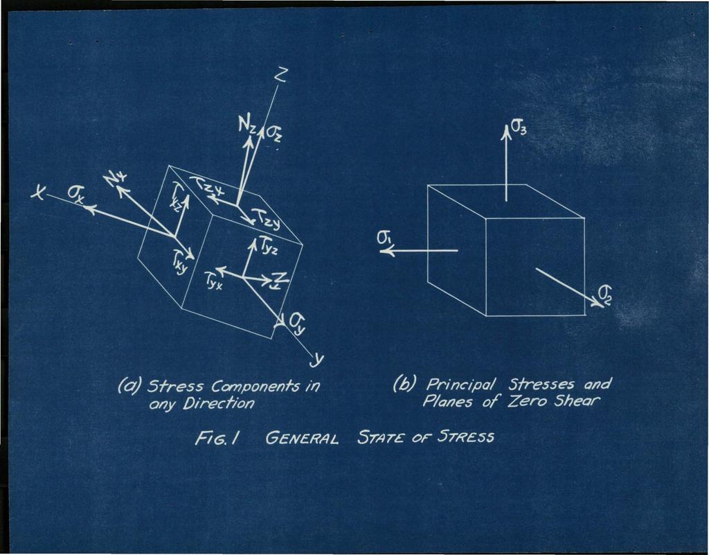
2 stress of 20,000 p.s.i. In the case of structural steel with a yield point of 33,000 p.s.i. the computed factor of safety would thus be A mare exact analysis of local stresses under bearing blocks or in the fillets might show ': these stresses to be above theoyield point of' the material. Naturally this does not mean that there is no factor of saf'ety. Actually, if' the beam in question is put in a testing machine and loaded it 1'1111 not yield as a structural unit until the computed stress by the beam formula is well - 2 above the yield-point stress of 33,000 p.s.i. The real taeof s4fetj tora.def'ined as the load ratio between the "general yielding" and the design load, will be nearer 2 than STRESS ANALYSES AND TB.E STATE OF STRESS. In studying the fundamental relations between the state of' stress and the physical properties of a ductile material it is essential to consider the three-dimensional character of stress. Imagine a very small cube eut.from the interior of any member under load as shown in Fig. la. The cube is imagined to be microscopic in size so that the resultant stress may be considered as uniform over each plane face. In general there may baa dif'ferent.resultant stress on:eachot: these three taces* with equal and oppositely directed stresses on the three faces hidden from view. Each of' these three stressas may be resolved into three components parallel with the x~
3 "'3 y., z, axes., The determination of these nine components of stress at every point in a structural member in accordance (, 'r ',. with the conditions ~:fstatic equilibrium, the equations of continuity or compatability, and the boundary conditions canst.itute a stre.ss analysis for a mathematically id&alized material. Solutions of typical problems may be found in.standard treati~es on the theory of elasticity. It is also possible to determine by photoelasticity the stress distribution in a Bakelite model which ia made to simulate the actual structure. Photoelasticstud1es have usually been t~o-d1.mensional but the extension to the three-dimenailtonal problem recently ~s been made possible l Stresses on the surface of actual structures may be explored by means of strain-rosettes. The stresses in th$ interior ot: dams have been determined by casting electric telemeters Or electric strain gages into the concrete. A variety of analogies are available for "",xperlmentally determining stresses :for e,er... taln sp~cla.l problems. It will be assumed here that by one of the foregoing methods a stress analysis has been obtained. What Is the significance ot' the stress analysis to the engineer? answer this question it is necessary to begin by relating the state of stress to the in!tial elastic.failure of the material. 1. THE FUNDAMFINTALS OF THREE "';DI MENSI ONAL PHOTOELASTI CITY M. Hetenyi~ A.3oM.E. Journa.l of Applied Mebhanlcs Vol. 5, No.4, p. A-149. To
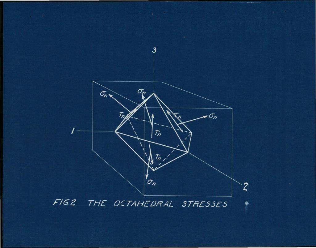
4 - 4 As 'a preliminary to the study of the yielding of materials it is convenient to simplify the three-dimensional state of stress illustrated in Fig. la. It is always possible to determine a new orientation of the direction ot th~ axes of the cube such that the ahearlng components will Vanish, leaving only the normal stresses 0;, <T',, and 03 as shown in lillg. lb. One of these priu"" clpal stresses will be a maximumstre,ssand another will be a minimum. Now consider an octahedron. constructed. by connecting the centers of each face ofa cube which is oriented in the principal directions as shown in Fig. 2. It may be shown2 that no matter what stat$ of stress exists at a particular location" the normal stress$s on each face of' the octahedron are identical and &qual to: cj'"l'i.. = 0: +lj~,+a; 3 Llkewise_ the magnitudes of the shear stress on each octahedral face are identical and equal to: T" ==- 3~ (6,-tJ,.r- +(o;.~o;)2. + (0; -cr;)~ Any state of stress thus reduces to a very simple concept which has part1culara1gnlfleanee when the in1tial plastic yielding ot a ductile material under any state of stress i's to bedetermlned. 2. THE:ORIES OF STREMG'l'H by A. Nadal. A.S.M.E. Journal of Applied Meehani cs, Vo1..1. Ns.3. July 1933, pp
5 ... 5 So THE RELATION BETWEEN STATE OF STRESS AND THE PHYSICAL PROPERTIES AND FAILURE OF MATERIALS Concepts regarding all of the physical properties of material are usually based on the behavior ot the material under one-d1reetiona1 loading in a tension or compression test~ In the actual structure the stress Is usually not ene-direetional and the physical p~opertles of the material. as usually conc~dved may no longer hold. The failure of the material will now be consid.ered, and two types of failure will be distinguished. In a Slmple tension test if the material elongateseonslderably after inltial yielding bet'ore it f'inally fractures it is said to be a ductile material. The initial plastic yielding will be termed elastic failure. A material whieh breaks suddenly in a simple tension test with little or no elongation 'or redu.ction in area. is termed til brittle material. Nadai3 and others have shown, however, that ductility and brittleness as exhibited by the type of' fracture and the ability to withstand permanent elongation without fracture depend not only on the nature of the material but on the state ot stress & well. The theory ofelastle failure which to date gives the best evaluation of in1tial plastic yielding in a ductile ma.ter'" lal under a state of combined stress is usually called the Von Mises-Hencky theory. It is also called the shear-strain energy 3. PLASTICITY by A. Nadai, Engineering Societies Monographs p.55
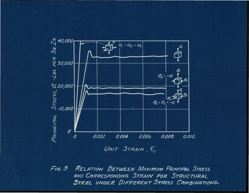
6 - 6 theory of.failure but may be deflned!vithout ret'erenee to strain energy as follew52: "Plastic yielding in a. ductile material will result when the octahedral shear stress reaches a certain lim1tlngvalue. 1J Let this limit of octahedral shear stress be denoted by h~. In a tension test with tensile stress a; acting in one.direction only the octahedral shearing stress T"lI\.= 0.47a;. If'dY.p.= 33,000 p.s.i. one may therefore state that elasti~ failure or plastic yielding in mild structural steel will oceur when the oetahedralshear stress'r"j=f 0.47 :It. 33,000 = 15,500 p.s. i. It should be kept in mind that the oe~a.hedral shear stress is usually not the maximum shear stress. Fig. 3 shows the stress-strain relations and initial yielding of structural steel as evaluated by this theory for three stre~s combinations in addition to simple tension. For the state of uniform all-around tenslen the load at initial plastic yielding is theoretically in1'lnite. It is experimenta.lly impractical to produce a uni.form a.lf\.around tension, but the conclusion 1s not inconsistent with the theory because in such a state of stress we mayexpeet no plastic yielding since no shearing stress is present. The "ductile" material would exhibit under a state of all-around tension the eharacteristlcs of a. brittle material. Brittle failures of this type may sometimes be caused by zones of three-dlrectional tension set up as internal stresses due to cooling.
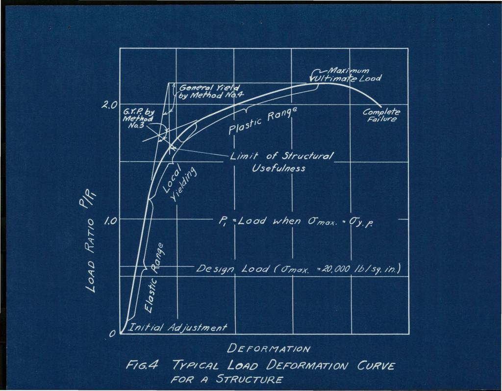
7 - 7 The yielding of material under a sta.te of uniform cambined stress has been discussed. What is the rel-ation between the yielding of the material and the general yieldingof the structural member? A tension member of uniform cross section such as an eyabar or a hollow tube in torsion are two of the rate instances in whieh a state of uniform stresscritically affects an entire structural member. In. such cases one may expect the member to yield and fail at loadsc.orresponding to the yield-point stress and ultimate strength of the materia.l. In other structures or structural mrl.ts, such as be~, columns, rigid frames, or f'loor slabs it is well known that general yielding of the structure does not coincide with the load at which the material at some particular point passes the yield point. THE LOAD-HISTORY OF THE STRUCTURE The load-history of' a material or of a structure is the complete record of its behavior from initial load to final failure. The load-h1story of the material is usually recorded by the stress strain graph of a standard tension test together with data regarding elongation, reduction in area, etc. The load-history of the structure as a whole may i be studied by plotting the load against a defleetion or de'" formation which is associated with the overa1l behavior of the structure as shown in Fig. 4. Ina rew special instances such as the bending of a beam or twisting of a circular rod
8 - 8 the load-history of the structure may be calculated analytically from that of the material by the theory of plastic1tis. Usually the structure is studied experimentally in the testing machine of the laboratory or under dead-weight loading in the field. On this subject Hardy C;oss states 4 : I'The interpretation of stress analysis makes absolutely necessary a clear idea of the action of the structural part up to the stage at which rupture is conceivable." The experimentally determined load histories of a standard tension test and the large scale test of a structural unit have qualitative similarities. The following 19ubdivi a1 ons may,be made for each cas,e: 1. Initial readjustments of grip,s or bearings at low load. 2. The elastic range, wherein load is proportional to deformation. 3. The proportional limt 4. The yielding of bar or structure. 5. Maximum ultimate load. 6. Final fracture or complete failure. A typical los'd-deformation curve such as shown in Fig.. 4 gives a graphical record of these stages in the load... history of the structure. ~. LIMITATIONS AND APPLICATIONS OF STRUCTURAL ANALYSIS Hardy Cross.; Part II, -Engineering News...Record, October 2." 1935, Vol. 115, No. 17, p. 571.
9 "'- - 9 In the elastic range the stress distribution on the surface of. the structure ma.y be determined experimentally bystrain--rasette readingsd,6 The proportianal lindtmay be determlnedapprqxlmately as the point at which the loaddeformation graph deviates from a straight line. Between the proportionalllm1t and the general yielding of a steel structure local Yielding may be noted by the flaking oft of mill scale.a.long well defined lines Which indicate the intersection between planes of maximum shear and the surface of the structure. The general yielding oftha structure is particularly lmportant as it is the reference point of a real 1"8.oto1'o safety. It usually represents a limit beyond which the strueture w1ll no longer usefully serve its ozolgina.1 purpose. Methods ror determining this "useful limit" correspond in some eases to those used in determining the yield point of a. materlal in a simple tension test. Four methods w1ll be out- - lined here. the useful lim!t of the structure in each case being' the load at whieh: 5. William R,. Osgood, DETERMINATION OF PRINCIPAL STRESSES FROM STRAINS ON FOUR INTERSECTING GAGE LINES 45 APART Bureau or Standards Journal or Research (R.P. No.SSl) Vol. 15, December R. D.. Mindlin., TEE EQUIANGULAR STRAIN-ROSETTE Civil Engineering, Vol. 8, No.8; August 1.939, p.546
10 A limiting amount or permanent derormation has taken place. 2. The slope ot the load~eformation curve is smaller than the slope of the original tangent by an arbitrarily determined ratio. S. The point at which the load-derormation curve has the highest rate of change of curvature. This may be determined a.pproximately by the construction shown in Fig A. point whl eh depends not only on the initial behavior but on the ultimate strength as well and which is obtained by the other construction shown in Fig. 4. Allor these methods have advantages and disadva.n'" tages. Method I Is the simplest and gives a well defined value but depends on specifying an arbitrary allowable deformation. Method 2 depends on specifying an arbitrary slope and also has the disadvantage of not giving a well defined point if the material or stracture yields slowly. Method 2 is quite satisfactory if there is a sharp break in the curve. Method:5 is ideal in obtaining very nearly the sharpest break in the curve and is especially adapted to types of.failure in which there is a secondary region above the yield point Where the cieformation Is nearly proportional to the strain. The last method, No.4, has the advantage of giving same weight to the ultimate strength of the material
11 - 11 or structure. Methods 3 and 4 have recently been tried out on a research project at the Fritz Laborat.oI'Y'7 and have the advantage that they do not depend on any arb!tn'arys.lopes or deformations. Method 4 1s the most definite and least arbitrary of all but may define a. limit of structural usefulness somewhat above the actual yield point in cases where the ultimate strength is high. In any actual research program satisfactory results should be obtained by the consistent use of anyone method whieh 1s judged to be best suited 'to the particular program in question. FACTORS WHICH INF'LUENCE THE LOAD-HISTORY OF A STRUCTURE The load-history and useful limit of a structure in a statie load test wi1l be affected by one or more of the following factors: 1. The physical properties of the material used. 2. The state or stress in various parts of: the structure. 3~ The degree to which maximum stresses are localized and the structural importance of this location. 4. The stability cf the structure and its component parts. The following specif:1e illustrations will demon... strate the influence of: these factors....-.' ' , - '.., ,,.. ' ~ 7. HIGH YIELD-POINT STEELS AS TENSION REINFORCEMENT IN BEAMS, Bruce Johnston and Kenneth Cox (unpib.blished February 19S9).
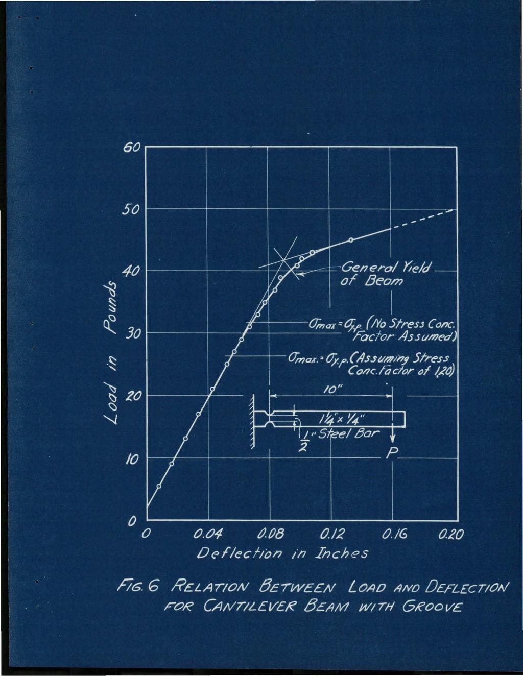
12 Stress Concentrations... It 1s.,.well known that stress concentrations due t(i)sharp reentry- corners or holes in structural m.embers cause higb.loealtzed stresses Fig. 5 shows theresultaot: tension teats3 on polished steels;i>eei... mens- all having the same netsectien. The apparent yield peint has been raised in the greoved bars because localcon~ $trletionis prevented by the,shape and by surrounding low ''Stressed areas. -12 The nominal ultimate strength is also ra.1.sed. because necking down is preve.nted sinee planes o:f sllp cam>.ot develop freely. The notehedbar'l, however, would undergo mu.chless detormation 'before fraetureoeeurred and the fracture'would beeharacterlst1e of a 'brittle, rather th8.n a. ductile materlal. These 'bars would be particularly poor in resis.tlng impact loads or repeatedstr es s. Stress concentrations have a similar effect in bending. A steel oar having two cireular g1:'00ve8 and. dimensions as shown in Flg.6!8.S loaded as a cantilever beam. The load... deformation diagram deviated almost imperceptibly from a $traigb.t line when the stress eoncentratlonsin the groove as determined photoela.sticallys reach-ed t~e yiel.d point of the mat$rla1. But the beam did not yield as a. structure until a load 53 per cent above that caleulated with the stress concentration effect inc.luded or 28 per eentabove theloa.d ealcu.lated by ordinary Mo M. Procht, FACTORS OF STRESSCONGENTRATIOll PHOTOEtASTIGALLY DETERMINED A.8.M.E. Journal of Applied Meehanicst Vol~ 2, No.2, June 1935, p.a--67
13 beam theory neglecting stress concentrations entirely. This higher strength is partly due to the lew stressed areas on either side of' the notch and partly due to the inherent reserve strength of a beam in bending which will be discussed as the next topic. Ef'fect of' Oross-Sectional Shape and Distribution i of' Load - The general yield or "useful limit" of an elastically stable beam always occurs ata load higher than - 13 the computed load at which the materia.l in the extreme ribera passes the yield""point stress of the material 9 For beams of equal section modulus loaded at the center with a single concentrated load the increase in useful limit is nearly one hundred per cent for a circular beam, over fifty per cent for a rectangular beam, and Is between fifteen and forty per cent for X-beam sections of various proportion. Plastic yielding for beams loaded at the center commences at a very localized region at the top and bottom of the center of the beam. the solid beams there is a large reserve of material but in the I -beam section most of the effect!va material in the cross section is immediately stressed above the yield point. Beams loaded at the third-points or uniformly have slightly lower useful lim!ts than corresponding beams with center loading. In the third-point loading all the extreme In 9. MODERN STRESS THEORIES. Discussion by E lt1irabelll of a paper by A.. V. Karpov. Transactions of the Am. Soc. C. E., Vol. 102, Fig. 48, p. 1401, 193'
14 - 14 fibers between the two load-points pass the'yie1d point at the same moment, thereby af.fectingat equal stress a greater percentage of the material.than in the case of center loading. The shape factor may be illustrated in torsion by compa.ring the moment-twist curves of a solid and hollow bar having the same polar moment of inertia.. In the hollow round bar all of the material is in a nearly uniform state of stress and in!tial yielding of material results at once in the general yielding of' the structure. In the solid bar there is a reserve elastic region after the outer fiber.s have exceeded their yield stress locally and asa result.o.i'. the general yield strength is raised. The In luenee of both the shape and load faetors may be stated in another more general wa:y, i.e." the useful li~t or general yield point and the shape of the load~"" formation..curve after yielding depend on the relative per'" centage of material in which the yield point is exceeded and the rate at which this percentage changes. The' most effective shapes in the elastic region are, the most ineffective after the maximum stress passes the yield point. This is the natural result of' putting as much material as possible in the regions of highest stress.
15 - 15 Other Faetora... If the structure is statically indeterminate other factors affect the load-hlstory of the structure. The complete yielding of' one part of an indeterminate structure ma.y still leave a stable structure. As an example one may consider a frame conststing of two columns and a horizontal beam attached to the columns by angle connections. After the eonneetionsstarted to yield the load deformation curve would continue on a new slope but the structure would still be quite safe as it would be in a state of transition.from a. continuous frame over into a statically determinate system consisting of' two columns and a simply supported beam between. One example in the field of' bubkling will illustrate another possibility. If plate girders with vertical stiffeners were made with webs thinner than are allowed now one could design a web which would buckle at extremely low loads. Although the web would quickly become useless in compression it would still be able to carry tensile forces from the top of one vertical sti.f'fener to the bottom of the next. The intermediate stiffeners would serve as compression struts and the girder would &s a result behave as a truss instead of a beam. Aeronautical engineers consider this fact in designing wing girders.
16 WORKING STRESSES AND DESIGN i. Examples have been given to illustrate some of' the many factors which affect the strength. of'a structure. "'16 \f.hat is really desired is a safe structure and every type of structure behaves to a certain extent by lawade:termined by ita own peculiar charaeteristics. To repeat -the real factor of safety in ~ystructure is not the ratio between calculated working stress and yield...point stress but rather the load ratio between working design load and load at the limit of struetural usefulness. In connection with present design methods the important problem in every case 1s to specify the correct allowable workingstresses to g1va a. safe l.oad ratio. In some cases it may be necessary to also specify the manner or degree of precision with Which the stresses are to be computed. This may be important because the calculated stresses. may be an approximation which depend for their exaetness entirely on the method of eomputation used. In unasual.design problems requiring special stress analyses by methods of ela.stlcity or photoelastieityeonsiderationmust be given not only to the magnitude 0' themaximu.m stresses but to their 16cabion$l' state 0' combination" and probable e' rect on the behavior ot the structure as a whole. No de.flniteworking stresses can be specl.fied ins'tlch eases. The principal problem of the structural desi'gner is that of proportioning a structure which..ill be both economical
17 and safej and which will give satisfactory service in these respects throughout it$ useful life. New types of structures such as concrete shell domes, steel rigid.frames, and welded structures of all kinds. are coming into U$6). These require experimental and theoretical research in orde;rto eval;uate the allowable loads and allowable computed stresses. The factors which have been discussed as well as other prae" tical questions silchas expected corrosion" rep.etitionof stress, expected tife of structure,ahd hazard to human life - all have a bearing on the selection of the proper allowable unit stress to determine a load factor 'Which w1~1 result in a sat'e and enduring 8tructure~
18
19
20
21
.8e II!:! ~ I 4~.")
22 -~-- -- (/NANNEALCD ANNEALED TENSILE 5?CC//'1EN Flrsf t/pper Lower First (Jpper Lower Y/e/d;1'l2'j YI? yp YI eldtn~ Y:? VI? ~ - n {). 5!)~ =-- lj. I KIps 'per Sr ware Inch z.~ r' Q55'".---~ C/, 15"d ro. f!i" I r - - ~--~-. - J~"... ~ /8 A ".. "t-- r ~ Q40" -o/s'rod. 1.. ~ ~O59" - ().8e II!:! ~ I 4~ /4-38/ FiG. 5 T II/~/ON TESTS OF GROOVED!3ARS (#ADA;)
23
The designs, depending upon the methods used, may be classified as follows:
 Definition Machine Design is the creation of new and better machines and improving the existing ones. A new or better machine is one which is more economical in the overall cost of production and operation.
Properties in Shear. Figure 7c. Figure 7b. Figure 7a
 Properties in Shear Shear stress plays important role in failure of ductile materials as they resist to normal stress by undergoing large plastic deformations, but actually fail by rupturing under shear
CH 6: Fatigue Failure Resulting from Variable Loading
 CH 6: Fatigue Failure Resulting from Variable Loading Some machine elements are subjected to statics loads and for such elements, statics failure theories are used to predict failure (yielding or fracture).
When an axial load is applied to a bar, normal stresses are produced on a cross section perpendicular to the axis of the bar.
 11.1 AXIAL STRAIN When an axial load is applied to a bar, normal stresses are produced on a cross section perpendicular to the axis of the bar. In addition, the bar increases in length, as shown: 11.1
VARIOUS TYPES OF SLABS
 VARIOUS TYPES OF SLABS 1 CHOICE OF TYPE OF SLAB FLOOR The choice of type of slab for a particular floor depends on many factors. Economy of construction is obviously an important consideration, but this
CE 221: MECHANICS OF SOLIDS I CHAPTER 3: MECHANICAL PROPERTIES OF MATERIALS
 CE 221: MECHANICS OF SOLIDS I CHAPTER 3: MECHANICAL PROPERTIES OF MATERIALS By Dr. Krisada Chaiyasarn Department of Civil Engineering, Faculty of Engineering Thammasat university Outline Tension and compression
How Beams Work, I. Statics and Strength of Materials
 How Beams Work, I Statics and Strength of Materials HOW BEAMS WORK Beams work by transferring transverse loads along their length to their supports primarily by resisting a force called internal bending
MECHANICS OF SOLIDS IM LECTURE HOURS PER WEEK STATICS IM0232 DIFERENTIAL EQUAQTIONS
 COURSE CODE INTENSITY PRE-REQUISITE CO-REQUISITE CREDITS ACTUALIZATION DATE MECHANICS OF SOLIDS IM0233 3 LECTURE HOURS PER WEEK 48 HOURS CLASSROOM ON 16 WEEKS, 96 HOURS OF INDEPENDENT WORK STATICS IM0232
Introduction to Structural Analysis TYPES OF STRUCTURES LOADS AND
 AND Introduction to Structural Analysis TYPES OF STRUCTURES LOADS INTRODUCTION What is the role of structural analysis in structural engineering projects? Structural engineering is the science and art
Structural design criteria
 chapter three Structural design criteria Contents 3.1 Modes of failure... 3.2 Theories of failure... 3.3 Theories of failure used in ASME Boiler and Pressure Vessel Code... 3.4 Allowable stress limits
P A (1.1) load or stress. elongation or strain
 load or stress. elongation or strain") load or stress MEEN 3145 TENSION TEST - BACKGROUND The tension test is the most important and commonly used test in characterizing properties of engineering materials. This test gives information essential
load or stress MEEN 3145 TENSION TEST - BACKGROUND The tension test is the most important and commonly used test in characterizing properties of engineering materials. This test gives information essential
Question Paper Code : 11410
 Reg. No. : Question Paper Code : 11410 B.E./B.Tech. DEGREE EXAMINATION, APRIL/MAY 2011 Fourth Semester Mechanical Engineering ME 2254 STRENGTH OF MATERIALS (Common to Automobile Engineering and Production
Mechanical Engineering
 Mechanical Engineering Strength of Materials Comprehensive Theory with Solved Examples and Practice Questions Publications Publications MADE EASY Publications Corporate Office: 44-A/4, Kalu Sarai (Near
Strength of Non-Prismatic Composite Self-Compacting Concrete Steel Girders
 Strength of Non-Prismatic Composite Self-Compacting Concrete Steel Girders *Haitham H. Muteb 1) and Mustafa S. Shaker 2) 1), 2) Department of Civil Engineering, UoB, Hillah 51002, Iraq 1) haithammuteb@gmail.com
STEEL DESIGNERS MANUAL
 STEEL DESIGNERS MANUAL SIXTH EDITION The Steel Construction Institute Edited by Buick Davison Department of Civil & Structural Engineering, The University of Sheffield Graham W. Owens Director, The Steel
Proportional Limit. Yield.Point. Ultimate Strength CHAPTER I. STREBB AND STRAIN
 ART --CHAPTER I STREBB AND STRAIN 1 Introduction 2 Types of Loading 3 Stresses Due to Central Loads 4 Stresses on Oblique Section 5 Strains Due to Central Loads 6 Stress-strain Cu~e Proportional Limit
Investigation of Structural Steel Webs for Punching Shear
 Journal of Civil Engineering and Architecture 9 (2015) 1126-1136 doi: 10.17265/1934-7359/2015.09.013 D DAVID PUBLISHING Investigation of Structural Steel Webs for Punching Shear Mustafa Mahamid 1 and Adeeb
BOUNDARY CONDITIONS OF SHEAR WALLS IN MULTI-STOREY MASONRY STRUCTURES UNDER HORIZONTAL LOADINGS
 BOUNDARY CONDITIONS OF SHEAR WALLS IN MULTI-STOREY MASONRY STRUCTURES UNDER HORIZONTAL LOADINGS K. ZILCH Professor, Institute of Building Materials and Structures Chair of Concrete Structures Technische
FE Review Mechanics of Materials
 1 2 3 4 5 6 7 8 9 10 11 12 13 14 15 16 17 18 19 20 21 22 23 24 25 26 27 28 29 1. T he element is subjected to the plane stress condition shown. a-x = - 140 M Pa a- y = 205 M Pa Txy = 100 M Pa What is t
Page 1 of 46 Exam 1. Exam 1 Past Exam Problems without Solutions NAME: Given Formulae: Law of Cosines: C. Law of Sines:
 NAME: EXAM 1 PAST PROBLEMS WITHOUT SOLUTIONS 100 points Tuesday, September 26, 2017, 7pm to 9:30 You are allowed to use a calculator and drawing equipment, only. Formulae provided 2.5 hour time limit This
When an axial load is applied to a bar, normal stresses are produced on a cross section perpendicular to the axis of the bar.
 11.1 AXIAL STRAIN When an axial load is applied to a bar, normal stresses are produced on a cross section perpendicular to the axis of the bar. In addition, the bar increases in length, as shown: 11.1
R13. II B. Tech I Semester Regular/Supplementary Examinations, Dec MECHANICS OF SOLIDS (Com. to ME, AME, AE, MTE) Time: 3 hours PART-A
 Time: 3 hours PART-A") SET - 1 II B. Tech I Semester Regular/Supplementary Examinations, Dec - 2015 MECHANICS OF SOLIDS (Com. to ME, AME, AE, MTE) Time: 3 hours Max. Marks: 70 Note: 1. Question Paper consists of two parts (Part-A
SET - 1 II B. Tech I Semester Regular/Supplementary Examinations, Dec - 2015 MECHANICS OF SOLIDS (Com. to ME, AME, AE, MTE) Time: 3 hours Max. Marks: 70 Note: 1. Question Paper consists of two parts (Part-A
Chapter 4 MECHANICAL PROPERTIES OF MATERIAL. By: Ardiyansyah Syahrom
 Chapter 4 MECHANICAL PROPERTIES OF MATERIAL By: Ardiyansyah Syahrom Chapter 2 STRAIN Department of Applied Mechanics and Design Faculty of Mechanical Engineering Universiti Teknologi Malaysia 1 Expanding
Structural Behaviour and Detailing
 Unit 22: Structural Behaviour and Detailing Unit code: M/601/1282 QCF level: 4 Credit value: 15 Aim This unit enables learners to understand structural concepts and develop skills to determine properties
 VALLIAMMAI ENGINEERING COLLEGE DEPARTMENT OF MECHANICAL ENGINEERING QUESTION BANK CE 6306 - STRENGTH OF MATERIALS UNIT I STRESS STRAIN DEFORMATION OF SOLIDS PART- A (2 Marks) 1. What is Hooke s Law? 2.
Code No: R Set No. 1
 Code No: R059210303 Set No. 1 II B.Tech I Semester Regular Examinations, November 2006 MECHANICS OF SOLIDS ( Common to Mechanical Engineering, Mechatronics, Metallurgy & Material Technology, Production
Contents. Tables. Notation xii Latin upper case letters Latin lower case letters Greek upper case letters Greek lower case letters. Foreword.
 Tables x Notation xii Latin upper case letters Latin lower case letters Greek upper case letters Greek lower case letters xii xiv xvi xvi Foreword xviii 1 Introduction 1 1.1 Aims of the Manual 1 1.2 Eurocode
MECHANICS OF MATERIALS
 Lecture Notes: Dr. Hussam A. Mohammed Al- Mussiab Technical College Ferdinand P. Beer, E. Russell Johnston, Jr., and John T. DeWolf Introduction Concept of Stress The main objective of the study of mechanics
PRESTRESSED CONCRETE STRUCTURES. Amlan K. Sengupta, PhD PE Department of Civil Engineering Indian Institute of Technology Madras
 PRESTRESSED CONCRETE STRUCTURES Amlan K. Sengupta, PhD PE Department of Civil Engineering Indian Institute of Technology Madras Module 5: Analysis and Design for Shear and Torsion Lecture-23: Analysis
CITY AND GUILDS 9210 Unit 130 MECHANICS OF MACHINES AND STRENGTH OF MATERIALS OUTCOME 1 TUTORIAL 1 - BASIC STRESS AND STRAIN
 CITY AND GUILDS 910 Unit 130 MECHANICS O MACHINES AND STRENGTH O MATERIALS OUTCOME 1 TUTORIAL 1 - BASIC STRESS AND STRAIN Outcome 1 Explain static equilibrium, Newton's laws, and calculation of reaction
SIDDHARTH GROUP OF INSTITUTIONS :: PUTTUR Siddharth Nagar, Narayanavanam Road QUESTION BANK (DESCRIPTIVE)
") SIDDHARTH GROUP OF INSTITUTIONS :: PUTTUR Siddharth Nagar, Narayanavanam Road 517583 QUESTION BANK (DESCRIPTIVE) Subject with Code :Strength of Materials-II (16CE111) Course & Branch: B.Tech - CE Year
SIDDHARTH GROUP OF INSTITUTIONS :: PUTTUR Siddharth Nagar, Narayanavanam Road 517583 QUESTION BANK (DESCRIPTIVE) Subject with Code :Strength of Materials-II (16CE111) Course & Branch: B.Tech - CE Year
ME 207 Material Science I
 ME 207 Material Science I Chapter 4 Properties in Bending and Shear Dr. İbrahim H. Yılmaz http://web.adanabtu.edu.tr/iyilmaz Automotive Engineering Adana Science and Technology University Introduction
Mechanical behavior of crystalline materials - Stress Types and Tensile Behaviour
 Mechanical behavior of crystalline materials - Stress Types and Tensile Behaviour 3.1 Introduction Engineering materials are often found to posses good mechanical properties so then they are suitable for
A Finite Element Approach to Reinforced Concrete Slab Design in GT STRUDL
 A Finite Element Approach to Reinforced Concrete Slab Design in GT STRUDL James Deaton and Dr. Kenneth M. Will 2006 GT STRUDL Users Group Meeting 23 June 2006 1 Introduction Background and Motivation The
SET PROJECT STRUCTURAL ANALYSIS OF A TROUGH MODULE STRUCTURE, IN OPERATION AND EMERGENCY Luca Massidda
 SET PROJECT STRUCTURAL ANALYSIS OF A TROUGH MODULE STRUCTURE, IN OPERATION AND EMERGENCY Luca Massidda Table of Contents Introduction... 2 Finite element analysis... 3 Model description... 3 Mirrors...
Nonlinear Finite Element Analysis of Composite Cantilever Beam with External Prestressing
 Nonlinear Finite Element Analysis of Composite Cantilever Beam with External Prestressing R. I. Liban, N. Tayşi 1 Abstract This paper deals with a nonlinear finite element analysis to examine the behavior
MACHINES DESIGN SSC-JE STAFF SELECTION COMMISSION MECHANICAL ENGINEERING STUDY MATERIAL MACHINES DESIGN
 1 SSC-JE STAFF SELECTION COMMISSION MECHANICAL ENGINEERING STUDY MATERIAL C O N T E N T 2 1. MACHINE DESIGN 03-21 2. FLEXIBLE MECHANICAL ELEMENTS. 22-34 3. JOURNAL BEARINGS... 35-65 4. CLUTCH AND BRAKES.
ARCH 331. Study Guide for Final Examination
 ARCH 331. Study Guide for Final Examination This guide is not providing answers for the conceptual questions. It is a list of topical concepts and their application you should be familiar with. It is an
MECHANICAL PROPERTIES
 MECHANICAL PROPERTIES Mechanical Properties: In the course of operation or use, all the articles and structures are subjected to the action of external forces, which create stresses that inevitably cause
5.4 Analysis for Torsion
 5.4 Analysis for Torsion This section covers the following topics. Stresses in an Uncracked Beam Crack Pattern Under Pure Torsion Components of Resistance for Pure Torsion Modes of Failure Effect of Prestressing
Chapter 2: Mechanical Behavior of Materials
 Chapter : Mechanical Behavior of Materials Definition Mechanical behavior of a material relationship - its response (deformation) to an applied load or force Examples: strength, hardness, ductility, stiffness
Members Subjected to Flexural Loads
 Members Subjected to Flexural Loads Introduction: In many engineering structures members are required to resist forces that are applied laterally or transversely to their axes. These type of members are
Ductility and Fracture of Joints with Panel Zone Deformation. Duktilitaet und Bruch von Rahmenknoten mit Stegverformung
 ,, 'P 467.7 FRITZ ENGINEERING LABORATORY LIBRARY Ductility and Fracture of Joints with Panel Zone Deformation Duktilitaet und Bruch von Rahmenknoten mit Stegverformung Le-Wu Lu, Roger G. Slutter and Seung
Nonlinear Finite Element Modeling & Simulation
 Full-Scale Structural and Nonstructural Building System Performance during Earthquakes & Post-Earthquake Fire A Joint Venture between Academe, Industry and Government Nonlinear Finite Element Modeling
Comparisons to Tests on Reinforced Concrete Members
 82 Chapter 6 Comparisons to Tests on Reinforced Concrete Members Finite element (FE) model predictions of laboratory test results of reinforced concrete members with various confinement methods are presented
BFF1113 Engineering Materials DR. NOOR MAZNI ISMAIL FACULTY OF MANUFACTURING ENGINEERING
 BFF1113 Engineering Materials DR. NOOR MAZNI ISMAIL FACULTY OF MANUFACTURING ENGINEERING Course Guidelines: 1. Introduction to Engineering Materials 2. Bonding and Properties 3. Crystal Structures & Properties
Cyclic Loading Tests Of Steel Dampers Utilizing Flexure-Analogy of Deformation
 Cyclic Loading Tests Of Steel Dampers Utilizing Flexure-Analogy of Deformation J.-H. Park & K.-H. Lee University of Incheon, Korea SUMMARY Steel dampers utilizing flexure analogy of deformation are proposed
THE MECHANICAL PROPERTIES OF STAINLESS STEEL
 THE MECHANICAL PROPERTIES OF STAINLESS STEEL Stainless steel is primarily utilised on account of its corrosion resistance. However, the scope of excellent mechanical properties the within the family of
Marian A. GIZEJOWSKI Leslaw KWASNIEWSKI Wael SALAH
 Robustness of continuous steel-concrete composite beams of slender plain webbed and cellular open webbed sections Marian A. GIZEJOWSKI Leslaw KWASNIEWSKI Wael SALAH Faculty of Civil Engineering Warsaw
(a) Pin-Pin P cr = (b) Fixed-Fixed P cr = (d) Fixed-Pin P cr =
 Pin-Pin P cr = (b) Fixed-Fixed P cr = (d) Fixed-Pin P cr =") 1. The most critical consideration in the design of rolled steel columns carrying axial loads is the (a) Percent elongation at yield and the net cross-sectional area (b) Critical bending strength and axial
1. The most critical consideration in the design of rolled steel columns carrying axial loads is the (a) Percent elongation at yield and the net cross-sectional area (b) Critical bending strength and axial
DIN EN : (E)
") DIN EN 1999-1-1:2014-03 (E) Eurocode 9: Design of aluminium structures - Part 1-1: General structural rules Contents Page Foreword to EN 1999-1-1:2007... 7!Foreword to EN 1999-1-1:2007/A1:2009... 7 #Foreword
DIN EN 1999-1-1:2014-03 (E) Eurocode 9: Design of aluminium structures - Part 1-1: General structural rules Contents Page Foreword to EN 1999-1-1:2007... 7!Foreword to EN 1999-1-1:2007/A1:2009... 7 #Foreword
Hyperstatic (Secondary) Actions In Prestressing and Their Computation
 Actions In Prestressing and Their Computation") 5.5 Hyperstatic (Secondary) Actions In Prestressing and Their Computation Bijan O Aalami 1 SYNOPSIS This Technical Note describes the definition, computation, and the significance of hyperstatic (secondary)
5.5 Hyperstatic (Secondary) Actions In Prestressing and Their Computation Bijan O Aalami 1 SYNOPSIS This Technical Note describes the definition, computation, and the significance of hyperstatic (secondary)
Compression Members. Columns I. Summary: Objectives: References: Contents:
 Compression Members Columns I Summary: Structural members subjected to axial compression are known as columns or struts. Stocky columns may not be affected by overall buckling. Stocky columns may fail
Introduction. Structures may be classified on the basis of materials used for construction, as follows: Steel structures. Aluminium structures
 Steel Structures 1 Introduction Structures may be classified on the basis of materials used for construction, as follows: Steel structures Aluminium structures Concrete structures Composite structures
MECHANICS OF MATERIALS. Mechanical Properties of Materials
 MECHANICS OF MATERIALS Mechanical Properties of Materials By NUR FARHAYU ARIFFIN Faculty of Civil Engineering & Earth Resources Chapter Description Expected Outcomes Understand the concept of tension and
CHAPTER 2. Design Formulae for Bending
 CHAPTER 2 Design Formulae for Bending Learning Objectives Appreciate the stress-strain properties of concrete and steel for R.C. design Appreciate the derivation of the design formulae for bending Apply
STRENGTH OF MATERIALS laboratory manual
 STRENGTH OF MATERIALS laboratory manual By Prof. Shaikh Ibrahim Ismail M.H. Saboo Siddik College of Engineering, MUMBAI TABLE OF CONTENT Sr. No. Title of Experiment page no. 1. Study of Universal Testing
BEAMS: COMPOSITE BEAMS; STRESS CONCENTRATIONS
 BEAMS: COMPOSITE BEAMS; STRESS CONCENTRATIONS Slide No. 1 Bending of In the previous discussion, we have considered only those beams that are fabricated from a single material such as steel. However, in
FME201 Solid & Structural Mechanics I Dr.Hussein Jama Office 414
 FME201 Solid & Structural Mechanics I Dr.Hussein Jama Hussein.jama@uobi.ac.ke Office 414 Lecture: Mon 11am -1pm (CELT) Tutorial Tue 12-1pm (E207) 10/1/2013 1 CHAPTER OBJECTIVES Show relationship of stress
Overview of Presentation. SCBFs are Conceptually Truss Structures
 Ultimate Strength and Inelastic Behavior of Braced Frame Gusset Plate Connections Charles W. Roeder University of Washington Department of Civil and Environmental Engineering Seattle, WA 98195 Structural
Welcome to ENR116 Engineering Materials. This lecture summary is part of module 2, Material Properties.
 Welcome to ENR116 Engineering Materials. This lecture summary is part of module 2, Material Properties. 1 2 Mechanical properties. 3 The intended learning outcomes from this lecture summary are that you
Design of a Beam Structure for Failure Prevention at Critical Loading Conditions
 International Academic Institute for Science and Technology International Academic Journal of Innovative Research Vol. 3, No. 10, 2016, pp. 32-44. ISSN 2454-390X International Academic Journal of Innovative
Sabah Shawkat Cabinet of Structural Engineering 2017
 3.1-1 Continuous beams Every building, whether it is large or small, must have a structural system capable of carrying all kinds of loads - vertical, horizontal, temperature, etc. In principle, the entire
True Stress and True Strain
 True Stress and True Strain For engineering stress ( ) and engineering strain ( ), the original (gauge) dimensions of specimen are employed. However, length and cross-sectional area change in plastic region.
MECHANICAL PROPERTIES OF MATERIALS
 MECHANICAL PROPERTIES OF MATERIALS Stress-Strain Relationships Hardness Effect of Temperature on Properties Fluid Properties Viscoelastic Behavior of Polymers Mechanical Properties in Design and Manufacturing
Chapter 8 Fatigue Strength and Endurance
 Chapter 8 Fatigue Strength and Endurance Screen Titles Fatigue Failure Process 1, 2 Fatigue Strength Testing S-N Diagram Fatigue Strength Equation 1, 2 Endurance Limit Behavior Endurance Limit Equations
10.5 ECCENTRICALLY LOADED COLUMNS: AXIAL LOAD AND BENDING.
 13 10.5 ECCENTRICALLY LOADED COLUMNS: AXIAL LOAD AND BENDING. Members that are axially, i.e., concentrically, compressed occur rarely, if ever, in buildings and other structures. Components such as columns
ME -215 ENGINEERING MATERIALS AND PROCESES
 ME -215 ENGINEERING MATERIALS AND PROCESES Instructor: Office: MEC325, Tel.: 973-642-7455 E-mail: samardzi@njit.edu PROPERTIES OF MATERIALS Chapter 3 Materials Properties STRUCTURE PERFORMANCE PROCESSING
ENGINEERING SOLID MECHANICS Fundamentals and Applications
 ENGINEERING SOLID MECHANICS Fundamentals and Applications Abdel-Rahman Ragab Salah Eldin Bayoumi CRC Press Boca Raton London New York Washington, D.C. Contents Chapter 1 Analysis of Stress 1.1 Rigid and
UNIT I SIMPLE STRESSES AND STRAINS, STRAIN ENERGY
 SIDDHARTH GROUP OF INSTITUTIONS :: PUTTUR Siddharth Nagar, Narayanavanam Road 517583 QUESTION BANK (DESCRIPTIVE) Subject with Code: Year & Sem: II-B.Tech & I-Sem Course & Branch: B.Tech - ME Regulation:
Chapter 7. Mechanical properties 7.1. Introduction 7.2. Stress-strain concepts and behaviour 7.3. Mechanical behaviour of metals 7.4.
 Chapter 7. Mechanical properties 7.1. Introduction 7.2. Stress-strain concepts and behaviour 7.3. Mechanical behaviour of metals 7.4. Mechanical behaviour of ceramics 7.5. Mechanical behaviour of polymers
NODIA AND COMPANY. GATE SOLVED PAPER Civil Engineering Design of Steel Structure. Copyright By NODIA & COMPANY
 No part of this publication may be reproduced or distributed in any form or any means, electronic, mechanical, photocopying, or otherwise without the prior permission of the author. GATE SOVED AER Civil
ST7008 PRESTRESSED CONCRETE
 ST7008 PRESTRESSED CONCRETE QUESTION BANK UNIT-I PRINCIPLES OF PRESTRESSING PART-A 1. Define modular ratio. 2. What is meant by creep coefficient? 3. Is the deflection control essential? Discuss. 4. Give
MOMENT REDISTRIBUTION IN CONTINUOUS BEAMS OF EARTHQUAKE RESISTANT MULTISTOREY REINFORCED CONCRETE FRAMES
 205 MOMENT REDISTRIBUTION IN CONTINUOUS BEAMS OF EARTHQUAKE RESISTANT MULTISTOREY REINFORCED CONCRETE FRAMES T. Paulay* ABSTRACT To allow a more uniform and efficient distribution of load resistance in
PORTAL FRAMES 1.0 INTRODUCTION
 36 PORTAL FRAMES 1.0 INTRODUCTION The basic structural form of portal frames was developed during the Second World War, driven by the need to achieve the low - cost building envelope. Now they are the
PRESTRESSED CONCRETE STRUCTURES. Amlan K. Sengupta, PhD PE Department of Civil Engineering Indian Institute of Technology Madras
 PRESTRESSED CONCRETE STRUCTURES Amlan K. Sengupta, PhD PE Department of Civil Engineering Indian Institute of Technology Madras Module 5: Analysis and Design for Shear and Torsion Lecture-24: Design for
1. Name the various sources of stress concentration in machine elements.
 TWO MARKS QUESTIONS 1. Name the various sources of stress concentration in machine elements. 2. What is meant by resilience of a body? 3. What are the factors to be considered for the selection of materials
Modelling of RC moment resisting frames with precast-prestressed flooring system
 Modelling of RC moment resisting frames with precast-prestressed flooring system B.H.H. Peng, R.P. Dhakal, R.C. Fenwick & A.J. Carr Department of Civil Engineering, University of Canterbury, Christchurch.
CODE PROVISIONS RELATED TO SOILS AND FOUNDATIONS
 68 CODE PROVISIONS RELATED TO SOILS AND FOUNDATIONS P.W. Taylor 1. INTRODUCTION In the new Loadings Code, NZS 4203 "Code of Practice for General Structural Design and Design Loadings", the basic seismic
How to Design a Singly Reinforced Concrete Beam
 Time Required: 45 minutes Materials: -Engineering Paper -Calculator -Pencil -Straight Edge Design For Flexural Limit State How to Design a Singly Reinforced Concrete Beam Goal: ΦMn > Mu Strength Reduction
International Journal of Advance Engineering and Research Development REVISION OF IS: A REVIEW (PART 2)
") Scientific Journal of Impact Factor (SJIF): 4.72 International Journal of Advance Engineering and Research Development Volume 5, Issue 01, January -2018 REVISION OF IS: 13920 A REVIEW (PART 2) Dr. Archana
Scientific Journal of Impact Factor (SJIF): 4.72 International Journal of Advance Engineering and Research Development Volume 5, Issue 01, January -2018 REVISION OF IS: 13920 A REVIEW (PART 2) Dr. Archana
To have a clear idea about what really happened and to prevent the
 Failure Analysis on Skunk-Arm of Electrical Tower Failure Analysis on Skunk-Arm of Electrical Tower ABSTRACT Ahmad Rivai 1, Md Radzai Said 2 1, 2 Faculty of Mechanical Engineering, Universiti Teknikal
15.2 Approximate Analysis of a Continuous Beam for Gravity Load
 15.2 Approximate Analysis of a Continuous Beam for Gravity Load Figure 15.1 Location of points of inflection and shear and moment curves for beams with various idealized end conditions 1 15.2 Approximate
Comparative Study of R.C.C and Steel Concrete Composite Structures
 RESEARCH ARTICLE OPEN ACCESS Comparative Study of R.C.C and Steel Concrete Composite Structures Shweta A. Wagh*, Dr. U. P. Waghe** *(Post Graduate Student in Structural Engineering, Y.C.C.E, Nagpur 441
Leelachai M, Benson S, Dow RS. Progressive Collapse of Intact and Damaged Stiffened Panels.
 Leelachai M, Benson S, Dow RS. Progressive Collapse of Intact and Damaged Stiffened Panels. In: 5th International Conference on Marine Structures (MARSTRUCT). 2015, Southampton, UK: CRC Press. Copyright:
Experimental and numerical validation of the technical solution of a brace with pinned connections for seismic-resistant multi-story structures
 Experimental and numerical validation of the technical solution of a brace with pinned connections for seismic-resistant multi-story structures Ramona Gabor, Cristian Vulcu, Aurel Stratan, Dan Dubina Politehnica
Office Building-G. Thesis Proposal. Carl Hubben. Structural Option. Advisor: Dr. Ali Memari
 Office Building-G Thesis Proposal Structural Option December 10, 2010 Table of Contents Executive Summary... 3 Introduction... 4 Gravity System...4 Lateral System:...6 Foundation System:...6 Problem Statement...
The problems in this guide are from past exams, 2011 to 2016.
 CE 311 Exam 1 Past Exam Problems, 2011 to 2016 Exam 1 (14% of the grade) THURSDY, 9/21 7 TO 9:30PM. OPTIONL Q& SESSION WED. 9/20, 8PM. COVERGE: LESSONS 1 TO 9 Exam is designed for 2 hours, but a maximum
ME 212 EXPERIMENT SHEET #2 TENSILE TESTING OF MATERIALS
 ME 212 EXPERIMENT SHEET #2 TENSILE TESTING OF MATERIALS 1. INTRODUCTION & THEORY The tension test is the most commonly used method to evaluate the mechanical properties of metals. Its main objective is
CADS A3D MAX. How to model shear walls
 CADS A3D MAX How to model shear walls Modelling shear walls in A3D MAX Introduction and synopsis This paper explains how to model shear walls in A3D MAX using the `wide column rigid arm sub-frame described
REINFORCED CONCRETE STRUCTURE COURSE STR 302A CL0SED BOOK EXAM THIRD YEAR CIVIL FIRST TERM YEAR TYPES OF SLABS
 REINFORCED CONCRETE STRUCTURE COURSE STR 302A CL0SED BOOK EXAM THIRD YEAR CIVIL FIRST TERM YEAR 2012 2013 COURSE CONTENTS : DESIGN OF DIFFERENT SLABS TYPES OF SLABS - Paneled Beam Slab - Stairs - Solid
Reinforced Concrete Design. A Fundamental Approach - Fifth Edition
 CHAPTER REINFORCED CONCRETE Reinforced Concrete Design A Fundamental Approach - Fifth Edition Fifth Edition REINFORCED CONCRETE A. J. Clark School of Engineering Department of Civil and Environmental Engineering
9/28/ :22 PM. Chapter 9. Welding and the Design of Permanent Joints. Dr. Mohammad Suliman Abuhaiba, PE
 9/28/2013 10:22 PM Chapter 9 Welding and the Design of Permanent Joints 1 2 9/28/2013 10:22 PM Chapter Outline 3 9/28/2013 10:22 PM Welding Symbols Welding symbol standardized by AWS Specifies details
Mechanical behavior of crystalline materials- Comprehensive Behaviour
 Mechanical behavior of crystalline materials- Comprehensive Behaviour In the previous lecture we have considered the behavior of engineering materials under uniaxial tensile loading. In this lecture we
Basic quantities of earthquake engineering. Strength Stiffness - Ductility
 Basic quantities of earthquake engineering Strength Stiffness - Ductility 1 Stength is the ability to withstand applied forces. For example a concrete element is weak in tension but strong in compression.
Load capacity rating of an existing curved steel box girder bridge through field test
 109 Dongzhou Huang Senior Engineer IV TS Transportation Design South Florida Atkins North America Load capacity rating of an existing curved steel box girder bridge through field test Abstract This paper
CHAPTER 1 INTRODUCTION
 CHAPTER 1 INTRODUCTION 1.0. GENERAL Modern civilization relies upon the continuing performance of civil engineering infrastructure ranging from industrial building to power station and bridges. For the
Analogy Methods to Address Warping and Plasticity in Torsion
 Paper ID #16398 Analogy Methods to Address Warping and Plasticity in Torsion Prof. Somnath Chattopadhyay, University at Buffalo, SUNY Dr. Somnath Chattopadhyay teaches mechanics, materials, manufacturing
Section A A: Slab & Beam Elevation
 CE 331, Spring 2011 Flexure Strength of Reinforced Concrete s 1 / 5 A typical reinforced concrete floor system is shown in the sketches below. The floor is supported by the beams, which in turn are supported
Load Deflection Behaviour of Restrained RC Skew Slabs Using FEM Technique
 Load Deflection Behaviour of Restrained RC Skew s Using FEM Technique Naresh Reddy G N Assistant Professor, School of Civil Engineering, REVA University, Rukmini Knowledge Park, Kattigenahalli, Yelahanka,