DRILLS ENDMILLS TAPS DRILLS ENDMILLS TAPS
|
|
|
- Robert Boone
- 6 years ago
- Views:
Transcription


1 75 Pushville Road, Greenwood, Indiana,, U.S.A. Phone: Toll Free: Fax: Toll Free Fax: Web Site: WEST COAST BRANCH 5 E. Alondra Blvd. Cerritos, California, 9070, U.S.A Phone: Toll Free: Fax: LATIN AMERICA BRANCH 5 N.W. 07th Ave., Miami, FL, U.S.A Phone: Fax: Courtland Ave., Unit Concord, Ontario Canada LK T Phone: Toll Free: Fax: Calle Tequisquipan, Aerotech Industrial Park, Localidad Galeras, Municipio de Colon, Queretaro, Mexico C.P. 795 Phone: Fax: BROACH/GEAR TOOLS Phone: Fax: BEARINGS HYDRAULICS MATERIALS ROBOTICS MACHINERY Phone: Fax: Shiodome Sumitomo Bldg. 7F, -9- Higashi-Shinbashi, Minato-ku, Tokyo, JAPAN Phone: Fax: Website: -- Fujikoshi-Honmachi, Toyama, JAPAN Phone: Fax: M.T..T DRILLS ENDMILLS TAPS DRILLS ENDMILLS TAPS
2 When You Buy From NACHI Contributing to Progress in the World of Product Manufacture NACHI-FUJIKOSHI CORP. NACHI-FUJIKOSHI CORP. The NACHI Difference CONVERSION TABLE


 PTY. LTD.")


3 NACHI-FUJIKOSHI CORP. JAPAN MAIN OFFICE Overseas Subsidiary Companies NACHI AMERICA INC. NACHI CANADA INC. NACHI MEXICANA, S.A. DE C.V. NACHI EUROPE GmbH NACHI TECHNOLOGY (THAILAND) CO., LTD. NACHI SINGAPORE PTE. LTD. NACHI (SHANGHAI) CO., LTD. NACHI (AUSTRALIA) PTY. LTD. FUJIKOSHI-NACHI (MALAYSIA) SDN. BHD. Overseas Plants NACHI TECHNOLOGY INC. NACHI TOOL AMERICA INC. NACHI BRASIL LTDA. NACHI INDUSTRIES PTE. LTD. NACHI PILIPINAS INDUSTRIES, INC.


4 THE NACHI DIFFERENCE -- MATERIAL AND HEAT TREATMENT Technical Data Clean Steel Clean Heat Treatment High-Speed Tool Classification High-speed steel Powdered High-speed steel Alloy tool steel JIS Steel type symbol AISI NACHI C Mo Chemical component W Cr V Co Application
5 THE NACHI DIFFERENCE -- MATERIAL AND HEAT TREATMENT Characteristics of Various Tool Materials Technical Data Type Symbol (Example) Production Method Features Carbon tool steel Alloy tool steel High speed steel Powdered high speed steel Cemented carbide Ultrafine grain cemented carbine Thermit Ceramic CBN sintered body Diamond sintered body Hardness of High-Hardness Material Vickers Hardness


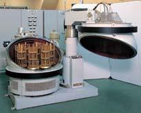
6 THE NACHI DIFFERENCE -- COATING TECHNOLOGY Technical Data DLC Coating Coating Series with Excellent Characteristics Composite Multi-Layer Coating Diamond Coating Coating Equipment
7 THE NACHI DIFFERENCE -- COATING TECHNOLOGY 5 Name G (TiN) Comparison of characteristics of NACHI coating film Evaluation of relative characteristics Features Technical Data SG (TiCN + TiN) UG (TiCN) AG (TiALN) X's (TiALN) AQUA (ALCRN base) DLC DIA
8 THE NACHI DIFFERENCE -- ECO & ECO CONCEPT Technical Data NACHI s Efficiency Theme Eco & Eco Sets The New Standard for Cutting Tools ECO = Economy of Cost Reduction ECO = Ecologically Friendly Achieving The Cost Efficient Environmentally Friendly Solution Reduction of Energy Consumption High Speed & Economical Environmentally Manufacturing Reduction of Coolant oil Dry & Semi-Dry Cutting NACHI s Efficient Eco & Eco Lines Dry & Semi-Dry Cutting Drilling Milling Tapping AQUA Drill Series for Steel, Hi-Temp Alloys, Stainless DLC Drill Series for Aluminum DLC Endmill Series for Aluminum X's Mill GEO Series for Steel X's Mill Series for Steel DLC TAFLET Series for Aluminum
9 THE NACHI DIFFERENCE -- ECO & ECO CONCEPT 7 Reducing Machining Costs If you can reduce coolant use, you can reduce cost by more than % The "Dry" Advantages The NACHI Solution High Speed and Cutting The Machining Energy Story The NACHI Solution High Speed & Cutting Reduced Machining Time E n e r g y Reduce Working and Static Energy Less Energy = High Speed Efficient Cutting ( High Speed & Cutting ) Drilling Milling NACHI High Speed & Lines AQUA Drill Series for Steel, Hi-Temp Alloys, Stainless AG /UG Power Series for Steel X's mill GEO Series X's mill Series
10 8 GUIDE TO MARK (TOOL SPECIFICATION) Technical Data Mark Explanation Mark Explanation Coating Tool Materials AQ EX Flutes of Drills Drill Dimension Lip Relief of Drills Thinning of Drills
11 GUIDE TO MARK (TOOL SPECIFICATION) 9 Mark Explanation Mark Explanation Tolerance of Drills Dia. Flutes of End Mills Flutes of End Mills Type of Taps Flutes of Taps Chamfer of Taps


12 VISUAL INDEX DRILLS ENDMILLS TAPS
13 Drills / Visual Index List 900 AQUA DRILL EX XD STUB / METRIC SIZES AQ EX h8 5 0 h * REPLACEMENT FOR List 9550 List 90 AQUA DRILL EX XD STUB / FRACTIONAL AQ EX List 90 AQUA DRILL EX 5XD JOBBER LENGTH / METRIC SIZES AQ EX List 90 AQUA DRILL EX 5XD JOBBER LENGTH / FRACTIONAL AQ EX P5, 57 P P57 P P58, 59 P P59 P List 90 AQUA DRILL EX OIL HOLE D / METRIC SIZES P0, List 905 AQUA DRILL EX OIL HOLE D / FRACTIONAL AQ P, List 90 AQUA DRILL EX OIL HOLE 5D / METRIC SIZES List 907 AQUA DRILL EX OIL HOLE 5D / FRACTIONAL P P P P P P List 908 AQUA DRILL EX OIL HOLE 8D / METRIC SIZES P, 5 List 909 h8 5 0 h * REPLACEMENT FOR List 955 h8 5 0 h * REPLACEMENT FOR List 955 h8 5 0 h * REPLACEMENT FOR List 955 AQ h7 5 EX 0 AQ h7 5 EX 0 h7 5 EX 0 AQ h7 5 EX 0 AQ h7 5 EX 0 h * REPLACEMENT FOR List 9558 h * REPLACEMENT FOR List 9558 h * REPLACEMENT FOR List 955 h * REPLACEMENT FOR List 955 h * REPLACEMENT FOR List 955 AQUA DRILL EX OIL HOLE 8D / FRACTIONAL AQ h7 5 EX 0 h * REPLACEMENT FOR List 959 HIGH PERFORMANCE DRILLS NEW NEW NEW NEW NEW NEW NEW NEW NEW NEW P P5 P
14 Drills / Visual Index List 90 AQ EX AQUA DRILL EX FLAT / METRIC SIZES NEW P, 7 P DRILLS List 9 AQ EX AQUA DRILL EX FLAT / FRACTIONAL NEW P7 P List 980 AQ EX AQUA DRILL EX FLAT RADIUS / METRIC SIZES NEW P7 P List 988 AQ EX 0º AQUA DRILL EX FLAT REGULAR / METRIC SIZES NEW P8 P List 98 AQUA DRILL EX FLAT LONG SHANK / METRIC SIZES AQ EX 0º NEW P9 P List 98 AQ EX AQUA DRILL EX FLAT OIL HOLE XD NEW P70 P5 List 98 AQ EX AQUA DRILL EX FLAT OIL HOLE 5XD NEW P7 P5
15 Drills / Visual Index List 98 AQ EX AQUA DRILL EX OIL HOLE FLUTE XD js 0º NEW P7 P List 980 AQ EX AQUA DRILL EX OIL HOLE FLUTE 5XD js 0º NEW P7 P DRILLS List 9 AQUA DRILL EX OIL HOLE 0D P7 AQ EX List 9 AQUA DRILL EX OIL HOLE 5D P7 AQ EX List 9 AQUA DRILL EX OIL HOLE 0D P7 AQ EX h7 0º h7 0º h7 0º Micro s.0 ~.0 Micro s.0 ~.0 Micro s.0 ~.0 NEW NEW NEW P-7 P-7 P-7 List 9 AQUA DRILL EX OIL HOLE MICRO COOLANT THRU P7 h7 50º Pilot Drill for L9, L9, L9 Series * NON-COOLANT * List 95 AQUA MICRO DRILLS / METRIC SIZES P75 P8
16 HIGH PERFORMANCE DRILLS List 95 MQL PILOT DRILLS List 95 List 95 MQL POWER LONG DRILLS P NEW List 757P SG-ESR DRILLS METRIC, List 7575P SG-ESR DRILLS FRACTIONAL NEW List 757P SG-ESS MICRO DRILL METRIC FAX HELIX NEW P >.9 List 757P STUB LENGTH SG-ESS / FRACTIONAL, WIRE, LETTER P
17 5 List 7570P JOBBERS LENGTH SG-ES / METRIC SIZES P List 757P JOBBERS LENGTH SG-ES / FRACTIONAL, WIRE, LETTER P List 759P List 759P SG DRILLS WITH OIL-HOLE P List 59P AG-SUS DRILLS SHORT / METRIC SIZES P List 59P AG-SUS DRILLS REGULAR / METRIC SIZES P * REPLACEMENT FOR List 58P List 595P AG-SUS DRILLS REGULAR / FRACTIONAL SIZES P * REPLACEMENT FOR List 57U List 50P List 5P AG-POWER LONG DRILLS P List 50 AG STARTING DRILL NEW List 50 AG STARTING DRILL NEW
18 Drills / Visual Index List 5 DLC-HSS DRILLS / METRIC SIZES P List 95 DLC MICRODRILLS / METRIC SIZES P List 950 DLC DRILLS REGULAR / METRIC SIZES P STRAIGHT SHANK DRILLS List 500 STRAIGHT SHANK JOBBERS LENGTH DRILL / METRIC SIZES STRAIGHT SHANK JOBBERS LENGTH DRILL / LETTER SIZES List 50 List 50A List 50 List 50 STRAIGHT SHANK COBALT DRILL TYPE I / METRIC SIZES List 50P G STANDARD DRILLS / METRIC SIZES P P P P P P
19 Drills / Visual Index STRAIGHT SHANK JOBBERS LENGTH DRILLS / FRACTIONAL List 50 P List 50A List 50 P P List 50P P List 57P P STRAIGHT SHANK JOBBERS LENGTH DRILLS / WIRE GAUGE SIZES List 50 List 50A List 50 List 50P List 57P P P P P P SCREW MACHINE LENGTH / FRACTIONAL SIZES List 5 List 5P P P
20 Drills / Visual Index SCREW MACHINE LENGTH / FRACTIONAL SIZES List 5 List 5 SCREW MACHINE LENGTH / WIRE GAUGE SIZES List 5 P P P List 5P P List 5 List 5 SCREW MACHINE LENGTH / LETTER SIZES List 5 List 5 List 5 STRAIGHT SHANK TAPER LENGTH / FRACTIONAL SIZES List 5 List 5 P P P P P P P List 55P P
21 Drills / Visual Index STRAIGHT SHANK DRILL-EXTRA LENGTH List 55 P List 55 List 58 OIL HOLE DRILLS / STRAIGHT SHANK P P TAPER SHANK DRILLS List 0 TAPER SHANK DRILLS / REGULAR SHANKS / FRACTIONAL P P List 8 OIL HOLE DRILLS / TAPER SHANK P SPECIAL List 575 SILVER AND DEMING DRILLS P List 599 DRILL SETS / JOBBERS LENGTH P
22 0 HIGH PERFORMANCE END MILLS END MILLS List 000 GENAC VGX FOUR FLUTE List 00 GENAC VGX FOUR FLUTE, CORNER RADIUS List 00 GENAC VGX FOUR FLUTE, BALL NEW List 98 GS-MILL TWO FLUTE List 98 GS-MILL FOUR FLUTE List 98 GS-MILL BALL List 908 MOLD MEISTER BALL List 998 GS-MILL HARD List 9 GS-MILL HARD BALL List 999 GS-MILL HARD / INCH SIZES List 9 GS-MILL HARD BALL / INCH SIZES List 9 X S-MILL GEO / METRIC SIZES NEW NEW P P P P P P P P P P P P
23 List 9 X S-MILL GEO / INCH SIZES List 9 X S-MILL GEO RADIUS List 98 X S-MILL GEO SLOT List 9 X S-MILL GEO KV TWO FLUTES List 98 X S-MILL GEO KV FOUR FLUTES List 90 X S-MILL GEO BALL List 9 X S-MILL GEO MICROBALL List 90 DLC-MILL FOR ALUMINUM / METRIC SIZES List 978 DLC-MILL SHARP CORNER TWO FLUTE List 90 DLC-MILL RADIUS List 990 DLC-MILL SLOT LONG SHANK List 90 DLC-MILL BALL List 50 DLC-HSS MILL / METRIC SIZES P P P P P P P P P P P P P END MILLS
24 END END MILLS MILLS List HD DLC-HSS MILL / INCH SIZES P List 85 AG-MILL ROUGHING / INCH SIZES List 0 AG-MILL HEAVY / INCH SIZES List 0 List 8 List 8 List 88 List 0 List 0 AG-MILL ROUGHING SHORT AG-MILL ROUGHING REGULAR LENGTH SHORT AG-MILL ROUGHING MEDIUM AG-MILL ROUGHING LONG AG-MILL HEAVY AG-MILL HEAVY LONG P P P P P P P P END MILLS GENAC END MILLS SG COATED CARBIDE List 9X P List 97X List 9X P P
25 GENAC END MILLS SG COATED CARBIDE List 97X List 95X List 97X ROUGHING AND FINISHING (HEAVY DUTY) END MILLS List 7 P P P P List 7X ROUGHING (HOG) END MILLS List 0 P P END MILLS List 0X List 07 TWO FLUTE END MILLS / REGULAR-SINGLE END List List X P P P P
26 TWO FLUTE END MILLS / LONG, SINGLE END List METRIC SIZES, REGULAR, SINGLE END List 0 List 0 MULTI FLUTE END MILLS / REGULAR SINGLE END CENTER CUTTING List M P P P P END MILLS List X MULTI FLUTE END MILLS / LONG SINGLE END, CENTER CUTTING List P P
27 5 HIGH PERFORMANCE TAPS List 955 DLC TAFLET THREAD FORMING TAPS / FRACTIONAL SIZES P List 957 P List 95 DLC TAFLET THREAD FORMING TAPS / METRIC SIZES P List 959 P List 958 SG LO-SPIRAL FLUTED TAPS / METRIC SIZES P VIPER T-SERIES List 798 VIPER T SERIES-SPIRAL FLUTED / GENERAL PURPOSE P List 797 VIPER T SERIES-SPIRAL POINTED / GENERAL PURPOSE VIPER T SERIES-METRIC TAPS / GENERAL PURPOSE List 7980 P P TAPS List 7970 List 7987 VIPER T SERIES-SPIRAL FLUTED / FOR STAINLESS STEEL P P
28 List 7977 VIPER T SERIES-SPIRAL POINTED / FOR STAINLESS STEEL P VIPER T SERIES METRIC TAPS / FOR STAINLESS STEEL List 798 P List 797 P VIPER TAFLET VIPER TAFLET FOR STEELS List 995 P List 995 P List 99 VIPER TAFLET METRIC TAPS FOR STEELS P TAPS VTP SPIRAL FLUTED List 98 VTP TAPS P List 98 P
29 7 VTP SPIRAL POINTED List 97 P List 97 P List 980 VTP METRIC TAPS SPIRAL FLUTED P List 98 VTP METRIC TAPS SPIRAL POINTED STANDARD TAPS STANDARD HAND TAPS List 9 P List 9 P TAPS
30 8 STANDARD TAPS SPIRAL POINTED / FRACTIONAL SIZES List 9 P List 99 STANDARD HAND TAPS / FOR CAST IRON P STANDARD TAPS SPIRAL POINTED / MACHINE SCREW SIZES List 9 P TAPS
31 9 TAPER PIPE TAPS / STRAIGHT FLUTED List 9 TAPER PIPE TAPS / SPIRAL FLUTED List 97 P P List 90 STANDARD METRIC HAND TAPS P List 90 STANDARD METRIC TAPS / SPIRAL POINTED P TAPS

32 DRILLS


 Flowing curve")
 (μm) Hole 00 50 00 50 00 50 000 5000")

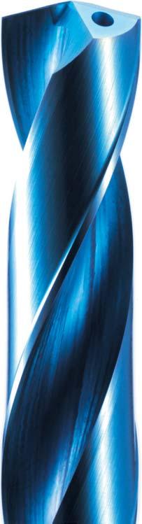
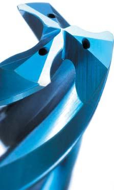
33 DRILLS TECHNICAL INFORMATION / AQUA EX DRILL NEW Features Designed for consistent high performance drilling in stainless steels to high temperature alloys. Unique J-shape flute design helps to generate easy chip break up. Smooth flute polishing facilitates fluid chip evacuation. Deep pockets ensure minimal chip packing. Aqua EX Drill Series Coating Aqua EX coating is designed for superior performance in both dry and wet conditions. EX = Exotic materials, extreme conditions. Engineered Per to withstand heavy wear and maintain consistent performance. AQUA EX coating Anti-Adhesive Coating Film TiAlCr type multi-layered film True Blue DRILLS Deep Pocket Tungsten Carbide Smooth Flute Long Tool Life Fine Chips with AQUA DRILL EX Cutting resistance is low SS00 S50C (Carbon Steel) Flowing curve Durability comparison Durability comparison (Service Life) (μm) Hole SCM0 (Alloy Steel) SKD (Tool Steel) AQUA Drill EX Competitor 0 AQUA Drill EX Competitor AQUA Drill EX Competitor Cutting Conditions NAK55 (Mold Steel) SUS0J (00 SS) Tool : AQDEXR.0 (L90) Speed : 00m/min (=500) : 0.8mm/rev (90mm/min) Work Material Cutting Fluid : : : IPR /.0 IPM S50C (Carbon Steel) Water Soluble

 00 00 Aqua EX 00 AQUA Drill EX Competitor 0 8")
 Cutting conditions : 0mm/min (IPR = 0.")
 Work Material : 0 Stainless Cutting Fluid : Water Soluble NEW AQUA")
 Engineered to handle the full range of applications.")


34 DRILLS TECHNICAL INFORMATION / AQUA EX DRILL Tool Life Features Delicate Cut Tough Heart DRILLS Comparison of wear after 5 Holes in 0 SS Crater Wear Comparison of wear on 0 SS 500 Competitor B Competitor A 00 Margin Wear WEAR (μm) Aqua EX 00 AQUA Drill EX Competitor CUTTING DEPTH (m) Tool : Ø9.0 5D Speed : 90m/min ( =,00) Cutting conditions : 0mm/min (IPR = / IPM = 5) Depth : 0mm (.57") Work Material : 0 Stainless Cutting Fluid : Water Soluble NEW AQUA DRILL EX DESIGN V/S AQUA DRILL AQUA Drill EX (New Design) AQUA Drill (Old Design) Engineered to handle the full range of applications. Aqua EX coating stands up to the highest temperatures. Optimal design for hard materials like Nickel / Titanium alloys. From start to finish designed with optimum chip evacuation in mind. Special cutting edge shape has superior wear resistance. High web thickness to increase tool rigidity Innovative AQUA coating was the first of it's kind. Not suitable for Stainless Steel TORQUE / THRUST COMPARISON AQUA Drill EX Competitor Thrust Thrust Torque Torque Time Time Consistent Thrust & Torque with Aqua Drill EX


35 DRILLS TECHNICAL INFORMATION / AQUA EX FLAT DRILL NEW Features One drill does it all - eliminates the need to use a center drill or end mill on inclined or curved surfaces. True 80º flat cutting edges create minimal exit burr in tubing and thin plates Ideally suited for flat bottom applications in the Oil, Gas, Automotive and General Industries. Double Margin for stable and precision drilling. DRILLS Per 80º True Flat Face Completely Flat Point Not a Flat Point Drilling Performance of Aqua Drill EX Flat Aqua EX Coating One Step Drilling with Minimal Burr Drilling for Eccentric Hole

36 DRILLS TECHNICAL INFORMATION / AQUA EX FLAT DRILL NEW SS00 Wear after 05m (00 ) DRILLS L90, L9 Non-Coolant Thru Stub Drill L988, L989 Non-Coolant Thru Jobber Drill L98, L987 Extended up to 0D Reach L98, L98 Coolant Thru D Flat Drill L98, L985 Coolant Thru 5D Flat Drill L980, L98 Ex Flat with Radius List No. Diameter Metric Fractional L L9 /8 - / L L989 /8 - / L L987 /8 - / L L98 /8 - / L L985 /8-5/8 L980 L /8 - / Applicable Work Materials Structural Steels Carbon Steels Pre-Hardened Steels Alloy Steels Hardened Steels Mold Steels Hardened Steels Stainless Steels Titanium Alloys Nickel Alloys Cast Irons Aluminum Alloys Copper Alloys = Great = Good

 0 Competitor Large vibrations AQDEXOH0D")
37 DRILLS TECHNICAL INFORMATION / AQUA DRILL EX MICRO COOLANT THRU NEW 5 Features Oil-Hole Drills for high efficiency drilling of small diameter deep holes Stable drilling of small diameter holes with new cutting edge geometry and large oil holes for efficient chip evacuation Suitable for wide work materials like Carbon Steels, Alloy Steels and Stainless Steels Multi-layered Aqua Ex Coating (TiALN+TiAlCr) plus anti-adhesive coating film for added lubrication DRILLS Performance New Oil Hole Design delivers coolant directly to the cutting edges New Cutting -Edge geometry breaks chips effectively Extremely smooth Aqua EX coating evacuates chips smoothly Smooth Drill Flute Surface Stable Drilling of Deep Holes Cutting Force Comparison (N-cm) 0 Competitor Large vibrations AQDEXOH0D Consistent vibrations Smooth coating surface for outstanding chip evacuation Torque Processing Time (Secs) Cutting Conditions Tool Ø Cutting Speed Work Material Ø.8 50 SFM (5m/min) 0.00 IPR (0mm/min) Carbon Steel (S50C) Coolant Type Hole Depth Step Interval Guide Hole Water Soluble - Coolant Thru 8. mm (.5 ) (0D) Blind Hole 0.7 (0.5 mm) / 0.5D AQDEXOHPLT085 for.8 mm hole Long Tool Life 00 No. of Holes (μm) Corner wear Competitor Initial wear breaking AQDEXOH0D Cutting Conditions Tool Ø Cutting Speed /Speed Hole Depth Step Interval Coolant Type Guide Hole Ø.0 50 SFM (5m/min) 0.00 IPR (0mm/min) 8. mm (.5 ) (0D) Blind Hole 0.7 (0.5 mm) / 0.5D Water Soluble - Coolant Thru AQDEXOHPLT005 for.0 mm hole 0 Competitor AQDEXOH0D Cutting Holes

38 DRILLS TECHNICAL INFORMATION / AQUA DRILL EX OIL-HOLE FLUTES NEW DRILLS Features High Precision drilling as deep as 5xD of drill. High accuracy achieved at high feed rate with optimized cutting edge form and superior drilling balance of -flutes. Multi-layered Aqua EX Coating (TiAlN + TiAlCr) Anti-adhesive coating film for added lubrication Performance Hole enlargement 5 Competitor 00 Holes Comparison of cutting force Cutting force is small, and controls amount of oversize. AQDEXOHF5D Competitor Hole enlargement (μm) 0 97 Holes 5 AQDEXOHF Holes Torquecm Torque Thrust Time Thrust (N) Torquecm Torque Thrust Time Thrust (N) Cutting condition SS00 Wear after 05m (00 ) Tools Ø Speed Ø 00 SFM (0m/min) 59 IPM 500mm/min (0.mm/rev) Carbon Steel (S50C) Water Soluble 0mm -. (5D) Work Material Type of Coolant Depth/Blind Hole 00 Wear (μm) Competitor formance of Aqua Drill EX Flat AQDEXOHF SUS0 Wear after 0m (0 ) Cutting length (m) Cutting condition Cutting condition Tools Ø Speed Ø 8 SFM (00m/min) 50 IPM 80mm/min (0.mm/rev) 00 Stainless (SS00) Work Material Water Soluble Type of Coolant 0mm -. (5D) Depth/Blind Hole Tools Ø Speed Ø SFM (50m/min) 8 IPM 80mm/min (0.8mm/rev) 0 Stainless (SUS0) Water Soluble 0mm -. (5D) Work Material Type of Coolant Depth/Blind Hole Applicable work materials Structural Steels SS00 Carbon Steels S5C/S50C Pre-Hardened Steels Alloy Steels SCR/NAK Hardened Steels Mold Steels Hardened Steels 0 0HRC 0 50HRC 50 5HRC X Stainless Steels Titanium Alloys Nickel Alloys Cast Irons SUS0/SUS SUS0 FCD/FC X Aluminum Alloys AC/ADC Copper Alloys Cu Great Good X Not Suitable

 Processing time Reamer Drill Center Drill 0 8 0")
39 DRILLS TECHNICAL INFORMATION / AQUA DRILL EX OIL-HOLE FLUTES 7 Performance -Flute Drill Cutting Speed 50 SFM (5m/min) Speed 0.00 IPR - IPM (00mm/min) Roundness.5 μm Cutting Conditions Tool Diameter Hole Depth/Blind Hole Work Material Cutting Fluid Ø mm mm (. ) SUS0 Water Soluble DRILLS Superior Hole Finish AQDE XOHF Cutting Speed Speed Roundness 70 SFM (50m/min) 0.07 IPR - IPM (570mm/min).7 μm Streamline Process & Reduce Cycle Time Usual Process AQDEX OHF + Center Drill Drill Reamer Drill AQDEXOHF Cycle Time (secs) Processing time Reamer Drill Center Drill Shortening of process and processing time Usual Process AQDEXOHF Cutting Conditions Diameter of Hole Ø H7 Hole Depth 0 mm Work Material Carbon Steel
 Precision ground end mill style shank for accurate and precision drilling.")

40 8 DRILLS TECHNICAL INFORMATION / SG ESR DRILLS NEW Features -Facet self-centering point Designed & Engineered for drilling Stainless Steel & Hi-temp alloys Made from Premium powdered metal cobalt substrate Composite Multi-layer SG Coating (Tin+TiCN) Precision ground end mill style shank for accurate and precision drilling. DRILLS Work Materials Hi-temp alloys Stainless Steels Alloy Steels Aluminum Alloys Carbon Steels Cast Irons Structural Steels Brass & Bronze Performance Equals Solid Carbide drill in performance in Stainless, Inconel & titanium. 0 ~ 0% Cheaper than Carbide Drills Self-centering point eliminates need for center drill operations. Well Suited for Drilling: Tool life in Carbon Steel Tool life in Alloy Steel SG Coating (Tin+TiCN) Number of Holes SG-ESR Drill Competitor Corner wear after drilling 80 holes Cutting Conditions Drill Diameter SFM () Work Material Hole Depth Cutting Fluid mm 0 (00) ipr /.5 ipm Carbon Steel 9mm (Through Hole) Water soluble Number of Holes SG-ESR Drill Competitor Chisel wear after drilling 00 holes Cutting Conditions Drill Diameter SFM () Work Material Hole Depth Cutting Fluid mm 90 (,00) 0.00 ipr / 5.7 ipm Alloy Steel(HRC) mm(blind Hole) Water Soluble Serious corner damage Collapse Tool life in 00-Series Stainless Tool life in 0 Stainless Steel Number of Holes SG-ESR Drill Competitor Corner wear after drilling 80 holes Cutting Conditions Drill Diameter SFM () Work Material Hole Depth Cutting Fluid mm 0 (00) ipr / 5.7 ipm 00-Series Stainless 9mm(Through Hole) Water soluble Number of Holes SG-ESR Drill Competitor SG-ESR after drilling0 holes Cutting Conditions Drill Diameter SFM () Work Material Hole Depth Cutting Fluid mm 0 (0) 0.00 ipr /. ipm 0 Stainless Steel 8mm(Through Hole) Water soluble Chipping Keep sharp edge : Great : Good : Not recommended Drill name Structural Steels SS00 Carbon Steels S5C/S50C Alloy Steels Pre-hardened Steels SCR/NAK Hardened Steels Mold Steels 00HRC Titanium Hardened Steels Stainless Steels Alloys Cast Irons Nickel 050HRC 505HRC 0SS/SS 00-Series Alloys FCD/FC Aluminum Alloys AC/ADC Copper Alloys Cu SGESR Drill
 End mill style shanks for highly precise and accurate drilling Work Materials Structural Steels, Carbon Steels, Alloy Steels, Stainless Steels, Cast Irons, Aluminum Alloys DRILLS")
41 DRILLS TECHNICAL INFORMATION / SG E SS & SG ES DRILLS 9 Features Utilizes a high accuracy shape of lip relief ( rake, rake + x-thinning) Made from premium powder metal with Composite Multi-Layer SG Coating (TiCN) End mill style shanks for highly precise and accurate drilling Work Materials Structural Steels, Carbon Steels, Alloy Steels, Stainless Steels, Cast Irons, Aluminum Alloys DRILLS Performance Streamline the process and reduce machining time dramatically. Eliminate the center drill operation with our SG-ESS drills (Stub length) Stable positioning within 0.000" (5μm) Faster feed & speed rates than regular HSS-Co drills Better cost performance than carbide drills SG-ESS Drills (stub length) Self centering point: SG-ES Drill (jobber's length): Positioning 5μm 0μm Brand A (TiN Coated) SG-ES Drill Performance and cutting data of SG drill series Surface properties (Smoothness) Characteristics of SG coating Wear resistance 5 0 TiN SG Toughness (μm) Enlargement Brand A (TiN Coated) SG-ES Drill Number of Drilled Holes Cutting Condition Drill Dia: 9.0mm. Hole Depth: mm Cutting Speed: 0m/min. (5. SFM) : mm/min (5. IPM) Work piece Material: Alloy steel (00HB) Machine: Vertical machining center Deposition resistance (for iron) Heat resistance Composite multi-layer film coating method characterized by improved wear resistance as compared to TiN.
42 0 DRILLS TECHNICAL INFORMATION / SG MICRO DRILLS NEW Features Premium PM-Cobalt Substrate with composite SG Coating (Tin+Ticn) Equals Solid Carbide Drill in performance due to tough PM Cobalt Substrate DRILLS Work Materials Structural Steels, Carbon Steels, Alloy Steels, Stainless Steels, Cast Irons, Aluminum Alloys Performance 0-0% more tool life than conventional HSS/HSCO micro drills. mm diameter end mill style shanks for highly precise and accurate drilling. Precision ground end mill style shank for accurate and precision drilling. Drilling Performance of SG-ESS Micro Drill Diameter Carbon Steel 0 Stainless Steel 0.5 mm Number of Holes SG-ESS Drill Competitor Number of Holes SG-ESS Drill Competitor SFM () Hole Depth Cutting Fluid 80 (5,500) ipr / 9. ipm.5mm (Blind Hole) Water solube SFM () Hole Depth Cutting Fluid (5000) ipr /.0 ipm.5mm (Blind Hole) 0.5mm-peck depth Water Solube 0.99 mm (μm) Wear After drilling 80 holes Margin wear SG-ESS Drill Competitor Number of Holes SG-ESS Drill Competitor SFM () Hole Depth Cutting Fluid 80 (8,000) ipr / ipm.5mm (Blind Hole) Water Solube SFM () Hole Depth Cutting Fluid 0 (,00) 0.00 ipr /.5 ipm mm (Blind Hole) 0.5mm-peck depth Water Solube Well Suited for Drilling: : Great : Good : Not recommended Drill name SGESS Structu al Steels SS00 Carbon Steels S5C/S50C Alloy Steels Pre-hardened Steels SCR/NAK Hardened Steels Mold Steels 00HRC Titanium Hardened Steels Stainless Steels Alloys Cast Irons Nickel Alloys 050HRC 505HRC 0SS/SS 00-Series FCD/FC Aluminum Alloys AC/ADC Copper Alloys Cu
 Micro Structure Conventional HSS Powder Metal HSS FM-HSS DRILLS Toughness Heat Resistance Wear Resistance GOOD EXCELLENT End mill style shanks for highly precise and accurate drilling Work")
 Hole Depth: 0mm through Speed: 78 SFM (.75 rpm) : 90mm/min (7.8 IPM) Pecking: Non Coolant: Emulsion TOOL LIFE 700 00 500 00 00 00 CHIP SHAPE- NACHI AG-SUS DRILL VS.")
 : 00mm/min (.")
43 DRILLS TECHNICAL INFORMATION / AG-SUS DRILLS Features Utilizes a high accuracy shape of lip relief ( rake thinning) Made from New HSS (FM-HSS: Fine melting HSS) with Composite Multi-Layer AG Coating (TiAIN) Micro Structure Conventional HSS Powder Metal HSS FM-HSS DRILLS Toughness Heat Resistance Wear Resistance GOOD EXCELLENT End mill style shanks for highly precise and accurate drilling Work Materials Austenitic Stainless Steels, Martensitic Stainless Steels, Feritic Stainless Steels, Structural Steels, Low Carbon Steels Performance CUTTING CONDITION Drill Dia.: mm Material: S00 (SUS0J) Hole Depth: 0mm through Speed: 78 SFM (.75 rpm) : 90mm/min (7.8 IPM) Pecking: Non Coolant: Emulsion TOOL LIFE CHIP SHAPE- NACHI AG-SUS DRILL VS. COMPETITOR FOR STAINLESS STEEL 00 0 AG-SUS Regular Drill Brand B AG-SUS DRILL COMPETITOR CUTTING CONDITION Drill Dia.: mm (0.09 ) Material: S0 (75 HB) Hole Depth: 5mm blind Speed: 9 SFM (.775 rpm) : 00mm/min (.9 IPM) Pecking: mm Coolant: Emulsion N U M B E R O F H O L E S AG-SUS Regular Drill Brand C Stocked Drill Name AG-SUS Drill Short/Metric s AG-SUS Drill Regular/Metric s AG-SUS Drill Regular/Fractional s List No. 59P 59P 595P Page
 and HSS-Co material increases tool life. DRILLS Work Materials Carbon Steels, Alloy Steels, Mold Steels, Hardened Steels (under 0HRC), Cast Irons Performance AG POWER LONG DRILL VS.")
44 DRILLS TECHNICAL INFORMATION / AG POWER LONG DRILLS Features New style Parabolic Drills Flute geometry and coating enables non pecking deep hole drilling up to 0XD. AG Coating (TiAlN) and HSS-Co material increases tool life. DRILLS Work Materials Carbon Steels, Alloy Steels, Mold Steels, Hardened Steels (under 0HRC), Cast Irons Performance AG POWER LONG DRILL VS. STANDARD DRILL AG Power Long Drill Competitor Stable Torque Torque is stable. Entry Side Exiting Side Clogging at 50mm depth. Broken at 8mm depth. CUTTING CONDITION Drill: mm (0.in) Material: 050 (7HB) S50C Hole Depth: 0 mm (.0in : 7D) through Speed: 590 rpm (98 SFM) : 0.mm/rev (. IPM) non-pecking drilling Fluid: Emulsion Entry Side Exiting Side Long Tool Life Number of Holes AG Power Long Drill Conventional Drill Competitor 0 Stocked Drill Name AG Power Long Drill/Metric s AG Power Long Drill/Fractional s List No. 50P 5P Page
45 DRILLS Features Cutting Performance DRILLS Limit Comparison at Drilling surface roughness and tool life in double margin Double Margin Single Margin Margin Non-Step Drilling Improves Machining Efficiency by 5x 5mm 5mm Work Materials MQL Pilot Drills Precision guide hole drills for MQL Long Drills Features Work Materials

 Material: AIMg.5 (A505) Hole Depth: 7.5mm (.0 ) blind Speed: 00m/min (8 SFM) : 0.08mm/rev (8.")
46 DRILLS TECHNICAL INFORMATION / DLC DRILLS Features Utilizes high accuracy shape of lip relief ( rake thinning) Utilizes flute geometry resulting in excellent chip control and dry milling with no edge build-up End mill style shanks for highly precise and accurate drilling DRILLS Work Materials Aluminums, Aluminum alloys, Aluminum Alloy Casting, Aluminum Alloy Die-casting, Copper alloys Performance WET DRILLING BY DLC DRILL Interruption After Drilling 000 Holes NUMBER OF HOLES DLC Drill Breaks After Drilling 570 Holes Non-Coat Carbide Drill CONDITION Drill: 5.5mm (0.5 ) Material: AIMg.5 (A505) Hole Depth: 7.5mm (.0 ) blind Speed: 00m/min (8 SFM) : 0.08mm/rev (8. IPM) Coolant: Emulsion Small wear after drilling 000 holes DRY DRILLING BY DLC DRILL NUMBER OF HOLES Break after drilling 57 holes DLC Drill Breaks After Drilling Holes Non-Coat Carbide Drill CONDITION Drill: 5.5mm (0.5 ) Material: ADC Hole Depth:.5mm (0.5 ) blind Speed: 00m/min (8 SFM) : 0.08mm/rev (8. IPM) Coolant: Dry Stocked Drill Name DLC HSS Drill/Metric s DLC Micro Drill/Metric s DLC Drill Regular/Metric s List No Page
47
48 Drills / Selection Chart HIGH PERFORMANCE DRILLS LIST No. Drill Name Material Coating Stock Product Page DRILLS Aqua Drill EX Stub Metric Fractional.0 to.0 /8 to 5/8 p.5, 57 p Jobber Aqua Drill EX Oil Hole Metric Fractional.0 to.0 /8 to 5/8 p.58, 59 p D Metric.0 to.0 Fractional /8 to 5/8 p.0, p D Metric Fractional.0 to.0 /8 to 5/8 p., p Aqua Drill EX Flat 8D Metric.0 to.0 Fractional /8 to 5/8 p., 5 p Stub Stub Carbide AQUA EX Metric.0 to.0 Fractional.0 to.0 p., 7 p Jobber Metric.0 to 0.0 p.8 98 Long Shank Metric.0 to 0.0 p.9 Aqua Drill EX Flat Oil Hole 98 XD Metric.0 to.0 p XD Metric.0 to.0 p.7 Aqua Drill EX Flute 98 Metric.0 to 0.0 p Aqua Drill EX Oil Hole Micro Metric.0 to.0 p.7 9 0D Metric.0 to.0 p.7 9 5D Metric.0 to.0 p.7 9 0D Metric.0 to.0 p.7 9 Metric.0 to.0 p.7 Aqua Drill 95 Micro Carbide AQUA Metric.0 to.99 p.75 Continue to next page...
49 7 : Great : Good : OK Drilling Depth * Workpiece Material Carbon Steel Alloy Die Hardened Steel Stainless Steel Cast Iron Aluminum Cutting Titanium Nickel Condition _ D _ 5D _ 7D >7D Low Carbon High Carbon Steel Steel HRc Austenitic Martensitic Alloys Alloys Soft Hard 0 Casting High Si Page 00,08 05,05 0,0 D up to 5 5 to 5 5 to 5 00 Series 00 Series < 00HB > 00HB 7075 Si _ % Si > % Aqua Drill EX LIST No p. p. Copper Alloys DRILLS 90 p. 90 p. Aqua Drill EX Oil Hole 90 p p. p. p. p. 909 p. Aqua Drill EX Flat 90 p p. p. 98 p. Aqua Drill EX Flat Oil Hole 98 p.5 98 p.5 Aqua Drill EX Flute 98 p. 980 p. Aqua Drill EX Oil Hole Micro 9 p. 9 9 p. p Aqua Drill Mist Hole 95 p.8 *Some sizes do not meet this preference. Please make sure of flute length of each size before use.
50 8 Drills / Selection Chart HIGH PERFORMANCE DRILLS LIST No. Drill Name Material Coating Stock Product Page DRILLS D 5D 0D 5D MQL SG Drills Pilot Power Long Carbide GS Metric Metric Fractional Metric Fractional to 7.5 /8 to / 5D,0D.0 to 0.0 5D.0 to 8.0 p.9 p.95 p P 7575P SG-ESR Metric.0 to.0 Fractional / to / p.9,97 p P Cobalt Micro Metric.0 to 0.0 p P Metric.0 to 0.0 p P Stub Fractional / to / p.0 757P PM-HSS SG Letter Wire B to Z # to #5 p P Metric.0 to 0.0 p P Jobbers Fractional / to / p.0 757P Letter Wire B to Z # to #5 p.0 759P 759P Oil Hole Metric 5.0 to 0.0 Fractional 5/ to / p.08 p.08 Continue to next page...
51 9 : Great : Good : OK Drilling Depth * Workpiece Material Carbon Steel Alloy Die Hardened Steel Stainless Steel Cast Iron Aluminum LIST Cutting Titanium Nickel Condition _ D _ 5D _ 7D >7D Low Carbon High Carbon Steel Steel HRc Austenitic Martensitic No. Alloys Alloys Soft Hard 0 Casting High Si Page 00,08 05,05 0,0 D up to 5 5 to 5 5 to 5 00 Series 00 Series < 00HB > 00HB 7075 Si _ % Si > % MQL Drills p.9 p.0 Copper Alloys DRILLS 95 p.0 SG Drills 757P p. 7575P 757P Micro 757P 757P 757P 7570P 757P 757P p. p. p. p. p. p. p. p. 759P p. 759P p. *Some sizes do not meet this preference. Please make sure of flute length of each size before use.
52 5 Drills / Selection Chart LIST No. Drill Name Material Coating Stock Product Page 59P AG Drills Short Metric.0 to 0.0 p.90 DRILLS 59P Regular 595P FMX Metric Fractional Metric Fractional.0 to 0.0 / to /.0 to.0 /8 to / p.9 p.9 p.9 p.9 HSS-Co 50 Metric.0 to 0.0 p.95 Starting Drill 50 Metric.0 to.0 p.95 50P AG Parabolic Power Long 5P DLC Drills HSS Metric.0 to.0 p.9 Micro DLC Metric 0.5 to.9 p.97 Carbide Regular Metric.0 to.0 p.98 STRAIGHT SHANK DRILLS LIST No. Drill Name Material Coating Stock Product Page 500 Jobbers Metric 0. to 7.5 p Black Oxide Fractional Wire / to / # to #0 p.0 p.0 50 Letter A to Z p.0 50A 50A Standard HSS Bright Fractional / to / Wire # to #80 p.0 p.0 50A Letter A to Z p.0 50P Fractional / to / p.05 50P TiN Wire # to #5 p.05 50P Metric 0.5 to.0 p.0 50 High Helix HSS-Co Black Oxide Metric 0.5 to.0 p Aircraft NAS 907- HSS-Co Black Oxide Fractional / to / p.0 Wire # to #80 p.0 50 Letter A to Z p.0 57P 57P Parabolic HSS TiN Fractional / to / Wire # to #5 p.0 p.0 Continue to next page...
53 5 : Great : Good : OK Drilling Depth * Workpiece Material Carbon Steel Alloy Die Hardened Steel Stainless Steel Cast Iron Aluminum LIST Cutting Titanium Nickel Condition _ D _ 5D _7D >7D Low Carbon High Carbon Steel Steel HRc Austenitic Martensitic No. Alloys Alloys Soft Hard 0 Casting High Si Page 00,08 05,05 0,0 D up to 5 5 to 5 5 to 5 00 Series 00 Series < 00HB > 00HB 7075 Si _ % Si > % AG Drills 59P p. Copper Alloys 59P 595P 50P 5P 50 p. p. p. p. DRILLS 50 DLC Drills 5 p p. p. : Great : Good : OK Drilling Depth * Workpiece Material Carbon Steel Alloy Die Hardened Steel Stainless Steel Cast Iron Aluminum LIST Cutting Titanium Nickel Condition _ D _ 5D _7D >7D Low Carbon High Carbon Steel Steel HRc Austenitic Martensitic No. Alloys Alloys Soft Hard 0 Casting High Si Page 00,08 05,05 0,0 D up to 5 5 to 5 5 to 5 00 Series 00 Series < 00HB > 00HB 7075 Si _ % Si > % Jobbers 500 p.5 Copper Alloys p.5 p.5 p.5 50A 50A 50A 50P 50P 50P P 57P p.5 p.5 p.5 p.5 p.5 p.5 p.5 p.5 p.5 p.5 p. p. *Some sizes do not meet this preference. Please make sure of flute length of each size before use.
54 Drills / Selection Chart STRAIGHT SHANK DRILLS LIST No. Drill Name Material Coating Stock Product Page 5 Screw Machine Fractional / to p.07 DRILLS 5 5 Standard Black Oxide Wire Letter # to #0 A to Z p.07 p.07 5P 5P HSS TiN Fractional Wire / to / # to #5 p.08 p.08 5 Fractional / to / p.09 5 Black Oxide Wire # to #5 p Aircraft NAS 907-C Letter Fractional A to Z / to / p.09 p.0 5 HSS-Co Black Oxide Wire # to #5 p.0 5 Taper Letter A to Z p Standard HSS HSS-Co Black Oxide Fractional / to / p. Fractional / to / p. 55P Extra Parabolic 8 HSS HSS TiN Bright Fractional / to / Fractional /8 to Fractional /8 to p. p. p Oil Hole Drill 0 HSS-Co HSS-Co Black Oxide Bright Fractional / to / Fractional /8 to -/ p.5 p. Continue to next page...
55 : Great : Good : OK Drilling Depth * Workpiece Material Carbon Steel Alloy Die Hardened Steel Stainless Steel Cast Iron Aluminum LIST Cutting Titanium Nickel Condition _ D _ 5D _7D >7D Low Carbon High CarbonSteel Steel HRc Austenitic Martensitic No. Alloys Alloys Soft Hard 0 Casting High Si Page 00,08 05,05 0,0 D up to 5 5 to 5 5 to 5 00 Series 00 Series < 00HB > 00HB 7075 Si _ % Si > % Screw AG Drills Machine 5 p.5 Copper Alloys 5 5 p.5 p.5 DRILLS 5P p.5 5P p.5 p.5 p.5 p.5 p.5 5 p.5 5 p.5 Taper 5 p.5 5 p.5 55P p. Extra 55 p. 55 p. 55 p. Oil Hole Drill 58 p.7 *Some sizes do not meet this preference. Please make sure of the flute length of each size before use.
56 Drills / Selection Chart TAPER SHANK DRILLS LIST No. Drill Name Material Coating Stock Product Page Taper Shank Drills 0 Regular Black Oxide Fractional 9/ to -/ p.7 DRILLS 5 5 Extra HSS-Co Bright Fractional Fractional / to -/ 5/ to -/ p.8 p.8 8 Oil Hole Drill HSS Bright Fractional /8 to -/ p.9 TAPER SHANK DRILLS LIST No. Drill Name Material Coating Stock Product Page Silver & Deming Drills 575 HSS Bright Fractional / to -/ p.0 Jobbers / Set Drills 599 HSS-Co Black Oxide, Bright Several Several p.
57 55 : Great : Good : OK Drilling Depth * Workpiece Material Carbon Steel Alloy Die Hardened Steel Stainless Steel Cast Iron Aluminum LIST Cutting Titanium Nickel Condition _ D _ 5D _ 7D >7D Low Carbon High Carbon Steel Steel HRc Austenitic Martensitic No. Alloys Alloys Soft Hard 0 Casting High Si Page 00,08 05,05 0,0 D up to 5 5 to 5 5 to 5 00 Series 00 Series < 00HB > 00HB 7075 Si _ % Si > % Taper Shank Drills Copper Alloys 0 5 p.8 p. DRILLS 5 p. 8 p.8 : Great : Good : OK Drilling Depth * Workpiece Material Carbon Steel Alloy Die Hardened Steel Stainless Steel Cast Iron Aluminum LIST Cutting Titanium Nickel Condition _ D _ 5D _ 7D >7D Low Carbon High Carbon Steel Steel HRc Austenitic Martensitic No. Alloys Alloys Soft Hard 0 Casting High Si Page 00,08 05,05 0,0 D up to 5 5 to 5 5 to 5 00 Series 00 Series < 00HB > 00HB 7075 Si _ % Si > % AG Silver Drills & Deming Drill Copper Alloys 575 p.8 Jobbers / Set Drills 599 p.5 *Some sizes do not meet this preference. Please make sure of the flute length of each size before use.
58 AQ EX Flute Shank Dia Item Code DRILLS List No. 900 Decimal Equivalent Flute Shank Dia Item Code Decimal Equivalent *Replaces List No. 9550
59 Flute Shank Dia Item Code Decimal Equivalent DRILLS Flute Shank Dia Item Code Decimal Equivalent Flute Shank Dia Item Code Decimal Equivalent Flute Shank Dia Item Code Decimal Equivalent AQ EX List No. 90 List. No
60 AQ EX Flute Shank Dia Item Code DRILLS List No. 90 Decimal Equivalent Flute Shank Dia Item Code Decimal Equivalent 955
61 Flute Shank Dia Item Code Decimal Equivalent DRILLS Flute Shank Dia Item Code Decimal Equivalent Flute Shank Dia Item Code Decimal Equivalent Flute Shank Dia Item Code Decimal Equivalent AQ EX List No. 90 List. No
62 Flute Shank Dia Item Code DRILLS List No. 90 Decimal Equivalent Flute Shank Dia Item Code Decimal Equivalent h7 5 h AQ EX
63 Flute Shank Dia Item Code Decimal Equivalent DRILLS Flute Shank Dia Item Code Decimal Equivalent Flute Shank Dia Item Code Decimal Equivalent Flute Shank Dia Item Code Decimal Equivalent List No. 905 List. No. 90 h7 5 h AQ EX
64 Flute Shank Dia Item Code DRILLS List No. 90 Decimal Equivalent Flute Shank Dia Item Code Decimal Equivalent h7 5 h AQ EX 0 955
65 Flute Shank Dia Item Code Decimal Equivalent DRILLS Flute Shank Dia Item Code Decimal Equivalent Flute Shank Dia Item Code Decimal Equivalent Flute Shank Dia Item Code Decimal Equivalent List No. 907 List. No. 90 h7 5 h AQ EX 0 955
66 Flute Shank Dia Item Code DRILLS List No. 908 Decimal Equivalent Flute Shank Dia Item Code Decimal Equivalent h7 5 h AQ EX 0 955
67 Flute Shank Dia Item Code Decimal Equivalent DRILLS Flute Shank Dia Item Code Decimal Equivalent Flute Shank Dia Item Code Decimal Equivalent Flute Shank Dia Item Code Decimal Equivalent List No. 909 List. No. 908 h7 5 h AQ EX 0 959
68 Flute Shank Dia Item Code DRILLS List No. 90 AQDEXZ Aqua Drill EX Flat L Decimal Equivalent Flute Shank Dia Item Code L Decimal Equivalent
69 Flute Shank Dia Item Code DRILLS List No. 9 L Decimal Equivalent Flute Shank Dia Item Code L Decimal Equivalent List No. 980 Flute Shank Dia Item Code L Decimal Equivalent Radius
70 Flute Shank Dia Item Code DRILLS List No. 988 AQDEXZR Aqua Drill EX Flat Regular L Decimal Equivalent Flute Shank Dia Item Code L Decimal Equivalent
71 DRILLS List No. 98 Flute Shank Dia Item Code L Decimal Equivalent Flute Shank Dia Item Code L Decimal Equivalent AQDEXZLS Aqua Drill EX Flat Extended
72 Flute Shank Dia Item Code HIGH PERFORMANCE DRILLS List No. 98 AQDEXZOHD Aqua Drill EX Flat Oil Hole XD L Decimal Equivalent Flute Shank Dia Item Code L Decimal Equivalent
73 HIGH PERFORMANCE DRILLS List No. 98 Flute Shank Dia Item Code L Decimal Equivalent Flute Shank Dia Item Code L Decimal Equivalent AQDEXZLS Aqua Drill EX Flat Oil Hole 5XD Drill Dia (in mm) Corner Chamfer
74 List No. 98 AQDEXOHFD Aqua Drill EX Oil Hole Flute D js 0º DRILLS Item Code Decimal Equivalent Flute Shank Dia Item Code Tolerance (js) Decimal Equivalent Flute Shank Dia
75 7 List No. 980 js 0º AQDEXOHF5D Aqua Drill EX Oil Hole Flute 5D Item Code Decimal Equivalent Flute Shank Dia Item Code Tolerance (js) Decimal Equivalent Flute Shank Dia DRILLS
76 List No. 9 h7 0º AQDEXOH0D Aqua Drill EX Oil Hole 0D DRILLS Item Code Flute Shank Dia List No. 9 Item Code Flute Shank Dia AQDEXOH5D Aqua Drill EX Oil Hole 5D Item Code Flute Shank Dia Item Code Flute Shank Dia List No. 9 AQDEXOH0D Aqua Drill EX Oil Hole 0D Item Code Flute Shank Dia Item Code Flute Shank Dia List No. 9 h7 50º AQDEXOHPLT Precision Guide Hole Drills for Aqua Micro Coolant Thru Drills Item Code Flute Shank Dia Item Code Flute Shank Dia
77 List No. 95 SOLID CARBIDE AQUA COATED EDP Decimal Equivalent Flute Shank Diameter EDP Decimal Equivalent Flute Shank Diameter EDP Decimal Equivalent Flute Shank Diameter
78 List No. 95 SOLID CARBIDE GS COATED DRILLS D Decimal Metric Equivalent Fractional D Decimal Metric Equivalent Fractional
79 SOLID CARBIDE GS COATED COOLANT THRU List No. 95 List No. 95 MQL Drills Recommended Cutting Conditions List No. 95 List No. 95 Guide Hole Drilling Initial Cutting with MQL Drill Deep Hole Drilling Retracting the Drill from the Hole 5 Breaking Through
80 DRILLS List No. 757P EDP No. EDP No.
81 7 DRILLS List No. 757P EDP No. EDP No.
82 8 List No. 7575P PM-HSCO SG Coated DRILLS EDP No. EDP No. SG-ESR DRILLS LIST NO. 757P, 7575P Workpiece Material Structural Steels Mold Steels Nickel Alloys Aluminum Alloys Alloy Steels Stainless Steels Cast Irons Copper Alloys Speed (SFM) Carbon Steels Series Titanium Alloys Nonferrous Alloys Drill Diameter 5-5 SFM SFM 0-50 SFM 0 SFM 0-50 SFM 00-0 SFM Fractional Metric Decimal mm (IPR) (IPR) (IPR) (IPR) (IPR) (IPR)
83 FAX h7 N HELIX 8 h7 Diameter Flute Shank Dia Item Code Diameter Flute Shank Dia Item Code DRILLS List No. 757P PM-HSCO SG Coated New Micro s
84 HIGH PERFORMANCE DRILLS Decimal EDP No. Shank Dia. Flute Wire Equivalent Decimal EDP No. Shank Dia. Flute Wire Equivalent #0 #59 #58 #57 #5 /" #55 #5 / # #50 #9 #8 5/ #7 # #5 # # # / # List No. 757P New Incremental s
85 HIGH PERFORMANCE DRILLS Decimal EDP No. Shank Dia. Flute Wire Equivalent Decimal EDP No. Shank Dia. Flute Wire Equivalent #0 #9 #8 #7 # 7/ #5 # # / #0 #9 #8,9/ #7 # # # List No. 757P
86 HIGH PERFORMANCE DRILLS Decimal EDP No. Shank Dia. Flute Wire Equivalent Decimal EDP No. Shank Dia. Flute Wire Equivalent / # # #0 #9 / #5 # / #0 #9 #7 / # #5 # # List No. 757P
87 HIGH PERFORMANCE DRILLS Decimal EDP No. Shank Dia. Flute Wire Equivalent Decimal EDP No. Shank Dia. Flute Wire Equivalent / # # List No. 757P
88 HIGH PERFORMANCE DRILLS List No. 757P EDP Fractional Wire Decimal Equivalent Metric Equivalent # # # # / # # # # # # / # # / # # / # # # # # # / # # # # / # # / # # # # / # # # # / # # Flute / / / / / / / / / / / 5/8 7/8 7/8 / 5/ 5/ / 5/ / / / / / /8 /8 / / / / /8 / / / / /8 5/ 5/ / / / / / / / 7/8 5/ 5/ /8 /8 /8 /8 7/ 7/ 7/ 7/ 7/ /8 / / / / /8 9/ 9/ /8 7/8 / / / / 7/8 /8 /8 Shank Decimal Metric EDP Dia. Fractional Letter Equivalent Equivalent /8 55 5/ /8 09 B /8 5 C /8 D /8 58 / /8 580 F /8 G 0.0. /8 57 7/ /8 50 I /8 7 J / / /8 7 L /8 80 M / / /8 / / / / / / N O Q / 50 R / 555 / / 55 / / U / 558 / / 50 V / 555 5/ / 58 X / 599 Y / 550 / / 0 Z / / / 558 7/ / / / 505 5/ / 5 / / 58 / / / / / / / / / / / / 8090 / / 8099 / / 8095 / / Flute / /8 /8 /8 / 7/ 7/ /8 / / /8 9/ 9/ /8 5/8 / / / / / 5/8 5/8 / 5/8 7/8 / 5/ 5/ / 7/8 7/8 7/8 7/8 / /8 7/ 7/ 9/ / / / / / / 5/ 5/ / /8 /8 / 7/ /8 / /8 / / / / 5/8 / / 7/8 / / 7/8 / /8 /8 /8 / / / 5 / 5 /8 5 5/8 5 / 5 5/ / Shank Dia. / / / / / /8 /8 /8 /8 /8 /8 /8 /8 /8 /8 /8 /8 /8 /8 /8 /8 /8 /8 /8 / / / / / / / / / / / / 5/8 5/8 / / / / 7/8 7/8
89 HIGH PERFORMANCE DRILLS List No. 7570P PM-HSS SG COATED EDP Decimal Equivalent Flute Shank Dia EDP Decimal Equivalent Flute Shank Dia EDP Decimal Equivalent Flute Shank Dia
90 List No. 757P PM-HSS SG COATED DRILLS EDP Decimal Fractional Wire Equivalent 9 # # # # / # # # # # # / # # / # # # / # # # # # / # # # # / # # # # # # / # # # # / # Metric Equivalent Flute /8 /8 / / /8 /8 /8 /8 7/ 7/ 7/ / / / /8 5/8 / / / 7/8 7/8 7/8 / /8 /8 /8 7/8 / / 7/ 7/ 7/ 7/ / 7/ / / / / 5/8 /8 /8 / / /8 5/8 5/8 / 7/8 7/8 7/8 / 5/ 5/ 5/8 / / / 7/8 5/ 5/ 5/ 7/ 7/ /8 7/ 9/ 9/ 9/ / 5/8 5/8 / / / / 7/8 / 5/ 5/ 5/ 7/8 7/ Shank Dia. /8 /8 /8 /8 /8 /8 /8 /8 /8 /8 /8 /8 /8 /8 /8 / / / / / / / / / / / / / / / / / / / / / / / / / / / / EDP Fractional Letter Decimal Equivalent Metric Equivalent # / B C D / F G / I J / L M / N / O / Q R / U / V / X Y / Z / / / / / / / / / / / / / Flute 5/8 /8 / / / /8 7/8 7/8 / 7/8 7/8 / 5/ / 7/8 / 7/8 / 7/8 7/ 7/ / 5/8 / 5/8 /8 / 7/8 /8 7/8 / / / / / / / / 5 /8 5 /8 5 / 7/ / 9/ 9/ 9/ / / / 5/8 / / 5/8 / 7/8 / 7/8 / 5 / 5 / 5 / 5 /8 5 7/ 5 /8 5 / 5 / 5 7/ 5 / 5 / 5 / 5 7/8 5 7/8 5 7/8 / / / / 7 / 7 5/8 7 / 7 7/8 Shank Dia. / / / / / / /8 /8 /8 /8 /8 /8 /8 /8 /8 /8 /8 /8 /8 /8 /8 /8 /8 /8 / / / / / / / / / / / 5/8 5/8 5/8 / / / 7/8 7/8
91 List No. 759P List No. 759P PM-HSS SG COATED DRILLS EDP Decimal Equivalent Flute EDP Decimal Equivalent Flute 505 5/ 0. -/8 -/ 507 / /8 -/ / 0.5 -/ -5/ / 0.8 -/ -5/ / /8 -/ 5 5/ 0.5-7/8 -/ 5 / 0.8-7/8 -/ 59 / 0.8 -/ 5-/8 55 / / 5-/8 55 / / 5-/8 58 5/ /8 5-/ 57 / 0.0 -/8 5-/ 580 7/ 0.9 -/ 5-7/ / / 5-7/8 50 9/ 0.5 -/ 5-7/8 59 5/ / 55 / 0.8 -/ 5 / / 58 7/ 0.5 -/ -/ 55 9/ / / / / / 7-/ 58 5/ / 7-/ 590 / / 505 / /8 7-5/8 5 / /8 7-/ 58 / / 7-7/8
92 List No. 59P FM HSS AG COATED DRILLS EDP Decimal Equivalent Flute Shank Dia EDP Decimal Equivalent Flute Shank Dia EDP Decimal Equivalent Flute Shank Dia
93 List No. 59P FM HSS AG COATED EDP Decimal Equivalent Flute Shank Dia EDP Decimal Equivalent Flute Shank Dia EDP Decimal Equivalent Flute Shank Dia DRILLS
94 List No. 595P FM HSS AG COATED DRILLS EDP Decimal Equivalent Flute Shank Diameter 87 / /8 -/8 / / / -/ /8 87 / /8-5/8 / / 0.0 -/ -7/8 / / 0.5 -/ -/8 / 8795 / /8 -/ / 8800 / /8 / 887 / 0.0 -/ -7/8 / 88 7/ / -7/8 / 880 5/ 0. -/8 -/ / 88 / /8 -/ / 885 7/ 0.5 -/ -5/8 / / 0.8 -/ -5/8 / / /8 -/ / / 0.5-7/8 -/ / / 0.8-7/8 -/ /8 890 / 0.8 -/ 5-/8 /8 890 / / 5-/8 /8 89 / / 5-/8 /8 89 5/ /8 5-/ / 899 / 0.0 -/8 5-/ / / 0.9 -/ 5-7/8 / 89 7/ / 5-7/8 / / 0.5 -/ 5-7/8 / 898 5/ / / 8990 / 0.8 -/ / 9005 / / / 90 7/ 0.5 -/ -/ 5/ / / 7 5/8 90 7/ / 7 5/ / / 7-/ / / / 7-/ / 90 / / / 9070 / /8 7-5/8 / 908 / /8 7-/ 7/8 909 / / 7-7/8 7/8 per tube
95 USA & JAPAN STOCK ITEM* List No. 50P HSS-Co AG COATED EDP Decimal Equivalent Flute EDP Decimal Equivalent Flute EDP Decimal Equivalent Flute DRILLS
96 List No. 5P HSS-Co AG COATED DRILLS EDP Fractional s Decimal Equivalent Flute 78 / / / / / / / / / / / / / / / / EDP Fractional s Decimal Equivalent Flute 797 / / / / / / / / / / / / / / / / EDP Fractional s Decimal Equivalent Flute 7 / / / / / / / /
97 Flute Shank Dia Item Code DRILLS List No. 50 AG Starting Drill Decimal Equivalent Drill Point Angle Flute Shank Dia Item Code List No. 50 AG Starting Drill Decimal Equivalent Drill Point Angle
98 JAPAN STOCK ITEM* List No. 5 HSS DLC COATED DRILLS EDP Decimal Equivalent Flute Shank Dia EDP Decimal Equivalent Flute Shank Dia per tube *JAPAN STOCK ITEM : Please allow - weeks delivery
99 JAPAN STOCK ITEM* List No. 95 SOLID CARBIDE DLC COATED EDP Decimal Equivalent Flute Shank Dia DRILLS
100 JAPAN STOCK ITEM* List No. 950 SOLID CARBIDE DLC COATED DRILLS EDP Decimal Equivalent Flute Shank Dia EDP Decimal Equivalent Flute Shank Dia EDP Decimal Equivalent Flute Shank Dia
101 DRILLS List No. 500 HIGH SPEED STEEL EDP Decimal Equivalent Flute EDP Decimal Equivalent Flute EDP Decimal Equivalent Flute
102 JAPAN STOCK ITEM* List No. 50 HIGH SPEED STEEL COBALT - Black Oxide DRILLS EDP Decimal Equivalent Flute EDP Decimal Equivalent Flute EDP Decimal Equivalent Flute
103 JAPAN STOCK ITEM* List No. 50P HIGH SPEED STEEL - TiN Coated EDP Decimal Flute Equivalent EDP Decimal Equivalent Flute EDP Decimal Equivalent Flute DRILLS
104 DRILLS List No. 50 HIGH SPEED STEEL Black Oxide EDP Fractional Wire Letter Decimal Equivalent Flute # / 5/8 000 # / 5/8 009 # / 5/8 005 # / / 00 # / / 008 / 0.09 / / 005 # /8 7/8 000 # /8 7/ # /8 7/8 008 / /8 7/ # /8 7/ # # # # / # # /8 / # /8 /8 008 # /8 /8 009 # / / 0008 # / / 00 / / / 000 # /8 / # /8 /8 00 # /8 / # / / 00 # / / 007 # / / / 0.09 / 5/ # / 5/ # 0.0 / 5/8 007 # 0.0 / 5/8 00 # 0.0 5/8 / 000 # /8 / 00 / /8 / 005 # /8 / 009 #9 0.0 / 7/ # / 7/ / 0.0 / 7/ # / # / # /8 EDP Fractional Wire Letter Decimal Equivalent Flute 005 # 0.50 /8 005 # 0.50 / / 0.5 / # /8 005 # /8 / #0 0.0 /8 / 0058 #9 0.0 /8 / # /8 / 00 # / /8 000 / 0.79 /8 / 009 # / /8 005 # / /8 00 # 0.80 / / # / / 00 / / / 0070 # / / 0087 # / / 009 # / 5/ # / 5/ # / 5/8 007 # / 5/ / 0.0 7/ 5/8 007 # 0.00 / / # / / 0077 # / / 0077 # 0.0 / / / 0.88 / / 0079 # 0.0 5/8 7/ # /8 7/ A 0.0 5/8 7/ / 0. 5/8 7/ B 0.80 / C 0.0 / D 0.0 / E / 008 / / F /8 / G 0.0 7/8 / / 0.5 7/8 / H 0.0 7/8 / I /8 / J /8 / K / / EDP Fractional Wire Letter Decimal Equivalent Flute / 0.8 5/ / L / / M / / / 0.99 / / N 0.00 / / / 0.5 / / O 0.0 / / P 0.0 5/ 5/ / 0.8 5/ 5/ Q 0.0 7/ / R / / 0088 / 0.8 7/ / S 0.80 / 7/ T / 7/ / 0.59 / 7/ U / / / V / W 0.80 / 5 / / 0.90 / 5 / X / 5 / Y /8 5 / 0097 / 0.0 7/8 5 / Z 0.0 7/8 5 / 009 7/ 0.9 5/ 5 / / 0.75 / 5 / / 0.5 / 5 5/ / / 5 / / 0.8 /8 5 7/ / / 9 / 0.55 / 5/8 75 7/ 0.5 / 5/8 8 5/ 0.59 / 5/8 98 9/ 0.55 / 5/8 70 7/ / 5/8 70 9/ / 7 /8 7 9/ / 7 /8 7 5/ / 7 /8 79 / / 7 /8 755 / / 7 /8 7 / /8 7 5/8 778 / /8 7 5/8
105 DRILLS List No. 50A HIGH SPEED STEEL Bright Finish EDP Decimal Flute EDP Decimal Flute Flute Fractional Wire Letter Equivalent Fractional Wire Letter Equivalent EDP Decimal Fractional Wire Letter Equivalent # /8 / 055 # / / 0557 E / # /8 / 058 7/ 0.09 / 5/ F /8 / / 0.05 / / 0559 # / 5/ G 0.0 7/8 / # / 7/ # 0.0 / 5/ / 0.5 7/8 / # / 7/8 055 # 0.0 / 5/ H 0.0 7/8 / # / 7/ # 0.0 5/8 / I /8 / # / 0558 # /8 / J /8 / # / 05 / /8 / K / / # / / # /8 / / 0.8 5/ / 0009 # / / #9 0.0 / 7/ L / / # /8 / 055 # / 7/ M / / # /8 / / 0.0 / 7/ / 0.99 / / # / / # / N 0.00 / / # / / # / / 0.5 / / 000 / 0.0 / /8 055 # / O 0.0 / / 000 # / / # 0.50 / P 0.0 5/ 5/ # 0.00 / /8 055 # 0.50 / / 0.8 5/ 5/ # /8 / 057 5/ 0.5 / Q 0.0 7/ / 0005 # /8 / # / R / / 0008 # /8 / # /8 / 0578 / 0.8 7/ / 0007 # /8 / 0559 #0 0.0 /8 / S 0.80 / 7/ # / 5/ #9 0.0 /8 / T / 7/ # / 5/ # /8 / / 0.59 / 7/ # / 5/ # / / U / # / 5/8 057 / 0.79 /8 / 0580 / / # / / # / / V / # / / 0555 # / / W 0.80 / 5 / / 0.09 / / # 0.80 / / / 0.90 / 5 /8 055 # /8 7/ # / / 0559 X / 5 / # /8 7/ / / / Y /8 5 / 055 # /8 7/ # / / 0587 / 0.0 7/8 5 / 0509 / /8 7/ # / / Z 0.0 7/8 5 / 0557 # /8 7/ # / 5/ / 0.9 5/ 5 / # # / 5/ / 0.75 / 5 / # # / 5/ / 0.5 / 5 5/ # # / 5/ / / 5 / 0557 # / 0.0 7/ 5/ / 0.8 /8 5 7/ / # 0.00 / / / / 055 # # / / 78 / 0.55 / 5/ # /8 / # / / 790 7/ 0.5 / 5/8 055 # /8 / # 0.0 / / 80 5/ 0.59 / 5/ # /8 / / 0.88 / / 8 9/ 0.55 / 5/ # / / 0557 # 0.0 5/8 7/8 89 7/ / 5/ # / / 0558 # /8 7/8 85 9/ / 7 /8 05 / / / A 0.0 5/8 7/8 8 9/ / 7 / # /8 / / 0. 5/8 7/ / / 7 / # /8 / B 0.80 / 8 / / 7 / # /8 / C 0.0 / 870 / / 7 / # / / D 0.0 / 887 / /8 7 5/8 055 # / / 057 / / 89 / /8 7 5/8
106 DRILLS List No HIGH SPEED STEEL COBALT Black Oxide EDP Decimal Flute Fractional Wire Letter Equivalent EDP Decimal Flute Decimal Flute Fractional Wire Letter Equivalent EDP Fractional Wire Letter Equivalent 057 # /8 / 005 # /8 /8 000 # 0.0 5/8 7/ # /8 / 000 # /8 /8 00 # /8 7/ / 0.05 / / 0077 # / / 0505 A 0.0 5/8 7/ # / 7/8 008 # / / 009 5/ 0. 5/8 7/ # / 7/ # / / B 0.80 / 058 # / 7/ / 0.09 / 5/ C 0.0 / 0580 # / 0005 # / 5/ D 0.0 / 058 # / 00 # 0.0 / 5/8 005 / / 058 # / /8 008 # 0.0 / 5/8 05 E / 0585 # / /8 00 # 0.0 5/8 / 058 F /8 / # /8 / 000 # /8 / 05 G 0.0 7/8 / # /8 / 0057 / /8 / 00 7/ 0.5 7/8 / # / /8 00 # /8 / 0557 H 0.0 7/8 / # / / #9 0.0 / 7/8 05 I /8 / / 0.0 / /8 008 # / 7/ J /8 /8 059 # / / / 0.0 / 7/8 058 K / / 059 # 0.00 / / # / / 0.8 5/ / 0599 # /8 / 00 # / L / / 0595 # /8 / 000 # /8 05 M / / # /8 / 007 # 0.50 /8 00 9/ 0.99 / / # /8 / 00 # 0.50 /8 057 N 0.00 / / # / 5/ / 0.5 / / 0.5 / / # / 5/8 00 # / O 0.0 / / # / 5/8 007 # /8 / 05 P 0.0 5/ 5/ # / 5/ #0 0.0 /8 / 0087 / 0.8 5/ 5/ # / / 0095 #9 0.0 /8 / 0589 Q 0.0 7/ / # / / 0000 # /8 / 0595 R / / / 0.09 / / 00 # / /8 009 / 0.8 7/ / # /8 7/8 007 / 0.79 /8 / 057 S 0.80 / 7/8 000 # /8 7/8 000 # / /8 05 T / 7/8 000 # /8 7/8 00 # / / / 0.59 / 7/ / /8 7/8 005 # 0.80 / /8 05 U / # /8 7/8 009 # / / 0075 / / # / / / 059 V / # # / / 0575 W 0.80 / 5 / # # / / 007 5/ 0.90 / 5 / # # / 5/ X / 5 / / # / 5/8 050 Y /8 5 / # # / 5/ / 0.0 7/8 5 / # /8 /8 005 # / 5/8 05 Z 0.0 7/8 5 / 000 # /8 / / 0.0 7/ 5/ / 0.9 5/ 5 /8 009 # /8 / # 0.00 / / / 0.75 / 5 / 005 # / / 005 # / / / 0.5 / 5 5/8 00 # / / # / / / / 5 / 059 / / / 0058 # 0.0 / / / 0.8 /8 5 7/8 008 # /8 / / 0.88 / / 0079 / /
107 List No. 50P HIGH SPEED STEEL-TIN COATED EDP Fractional Wire Decimal Equivalent Flute 0758 / /8 7/ # /8 7/ # # # # / # # /8 / # /8 / # /8 / # / / 00 # / / 50 / / / 00 # /8 /8 000 # /8 / # /8 / # / / 007 # / / 0095 # / / 7/ 0.09 / 5/ # / 5/8 008 # 0.0 / 5/ # 0.0 / 5/ # 0.0 5/8 / 0050 # /8 / 00 / /8 / 005 # /8 / 0059 #9 0.0 / 7/ # / 7/8 99 9/ 0.0 / 7/8 000 # /8 00 # /8 005 # /8 009 # 0.50 /8 007 # 0.50 / / 0.5 /8 009 # / # /8 / 000 #0 0.0 /8 / EDP Fractional Wire Decimal Equivalent Flute 007 #9 0.0 /8 / 007 # /8 / 007 # / /8 50 / 0.79 /8 / 000 # / /8 000 # / / # 0.80 / /8 000 # / / 5 / / / 007 # / / # / / 008 # / 5/ # / 5/ # / 5/ # / 5/ / 0.0 7/ 5/ # 0.00 / / 008 # / / 009 # / / 0008 # 0.0 / / 5 7/ 0.88 / / 007 # 0.0 5/8 7/ # /8 7/8 5/ 0. 5/8 7/8 59 / / 0 7/ 0.5 7/8 /8 09 9/ 0.8 5/ / 0 9/ 0.99 / /8 9 5/ 0.5 / / 085 / 0.8 5/ 5/ / 0.8 7/ / 085 / 0.59 / 7/8 085 / / / 0.90 / 5 / / 0.0 7/8 5 / / 0.9 5/ 5 / / 0.75 / 5 / / 0.5 / 5 5/ / / 5 / 08 / 0.8 /8 5 7/8 08 / / DRILLS
108 List No. 57P 5 HIGH SPEED STEEL-TIN COATED DRILLS EDP Fractional Wire Decimal Equivalent Flute 090 / /8 7/ # /8 7/ # # # # / # # /8 /8 09 # /8 / # /8 /8 095 # / / 0978 # / / 0978 / / / 0980 # /8 / # /8 / # /8 /8 008 # / / 005 # / / 00 # / / / 0.09 / 5/8 009 # / 5/8 005 # 0.0 / 5/8 007 # 0.0 / 5/ # 0.0 5/8 / 0059 # /8 / 005 / /8 / 0055 # /8 / #9 0.0 / 7/ # / 7/ / 0.0 / 7/8 008 # /8 000 # /8 008 # /8 007 # 0.50 / # 0.50 / / 0.5 / # / # /8 / 0088 #0 0.0 /8 / EDP Fractional Wire Decimal Equivalent Flute 009 #9 0.0 /8 / # /8 / 0057 # / /8 008 / 0.79 /8 / 0 # / /8 07 # / /8 0 # 0.80 / /8 075 # / / 08 / / / 00 # / / 08 # / / 055 # / 5/8 05 # / 5/8 059 # / 5/8 00 # / 5/8 07 / 0.0 7/ 5/8 00 # 0.00 / / 08 # / / 070 # / / 077 # 0.0 / / 07 7/ 0.88 / / 0779 # 0.0 5/8 7/8 080 # /8 7/8 08 5/ 0. 5/8 7/8 08 / / 087 7/ 0.5 7/8 / / 0.8 5/ / 089 9/ 0.99 / / / 0.5 / / 09 / 0.8 5/ 5/8 099 / 0.8 7/ / 095 / 0.59 / 7/8 098 / / / 0.90 / 5 / / 0.0 7/8 5 / 000 7/ 0.9 5/ 5 / / 0.75 / 5 / 00 9/ 0.5 / 5 5/ / / 5 / 007 / 0.8 /8 5 7/8 005 / /
109 List No. 5 HIGH SPEED STEEL Bright Finish EDP Decimal Flute Shank Decimal Flute Shank Decimal Flute Shank EDP Fractional Wire Letter Equivalent Dia. Fractional Wire Letter Equivalent Dia. EDP Fractional Wire Letter Equivalent Dia. 08 # / /8 # # 0.90 / / # 579 9/ 0.5 /8 9/ 9/ 0 # / /8 # # / / # / 0.88 /8 5/8 5/ 00 # / /8 # # / / #9 57 / 0.8 / / / 07 # / /8 #57 08 # / / # / / / / 05 # / /8 #5 080 # / / #7 578 / 0.55 /8 7/8 / 58 / 0.09 / /8 / 5589 / 0.0 / / / / 0.5 /8 7/8 7/ 07 # /8 5/8 #55 08 # 0.00 / /8 # 580 5/ 0.59 / 5/ 08 # /8 5/8 # # / /8 #5 58 9/ 0.55 / 9/ 099 # /8 5/8 #5 08 # / /8 # 589 7/ /8 /8 7/ 59 / /8 5/8 / 087 # 0.0 / /8 # 585 9/ /8 /8 9/ 00 # / / # / 0.88 / /8 7/ 58 9/ 0.09 / / 9/ 07 # / / # # 0.0 5/ 7/ # / / / 5/8 0 # / / # # / 7/ # 58 / 0.0 7/8 / / 00 # / / #9 097 A 0.0 5/ 7/ A 5870 / 0.5 7/8 / / 05 # / / # / 0. 5/ 7/ 5/ 5887 / /8 5/8 / / / / 5/ 090 B 0.80 /8 / B 589 / /8 5/8 / 079 # / / #7 09 C 0.0 /8 / C / 0.70 / 5/ 085 # / / # 095 D 0.0 /8 / D 595 / / / 09 # / / #5 57 / /8 / / 59 7/ 0.7 /8 5 7/ 007 # / / # 0975 E /8 / E 598 / /8 5 / 0 # / / # 098 F / 5/8 F 59 9/ 0.75 / 5 /8 9/ 00 # / / # 0998 G 0.0 7/ 5/8 G / 0.78 / 5 /8 5/ 55 / / / / 5 7/ 0.5 7/ 5/8 7/ 597 5/ /8 5 / 5/ 0 # / / # 009 H 0.0 / / H 597 / 0.85 /8 5 / / 059 # / / #0 005 I 0.70 / / I / 0.88 / 5 /8 5/ 05 # / / #9 00 J / / J 599 7/ 0.88 / 5 /8 7/ 07 # / / #8 008 K 0.80 / / K / / 5 / 55/ 088 # / / #7 50 9/ 0.8 / / 9/ 07 7/ / 5 / 7/8 09 # 0.05 / / # 000 L / / L 0 57/ /8 5 5/8 57/ 550 7/ 0.09 / / 7/ 0077 M / / M 00 9/ /8 5 5/8 9/ 05 # /8 7/8 #5 5 9/ / / 9/ 0 59/ 0.99 / 5 / 59/ 05 # 0.0 7/8 7/8 # 0090 N /8 / N 05 5/ / 5 / 5/ 059 # 0.0 7/8 7/8 # 55 5/ 0.5 5/8 / 5/ 09 / /8 5 7/8 / 055 # 0.0 7/8 7/8 # 0 O 0.0 / 5/ O 075 / /8 5 7/8 / 055 # /8 7/8 # 08 P 0.0 / 5/ P 08 / 0.98 / 557 / /8 7/8 /8 59 / 0.8 / 5/ / # / 5/ #0 00 Q 0.0 / Q 0 /.05 / 057 # / 5/ #9 057 R 0.90 / R 0 /8.50 / # / 5/ #8 575 / 0.8 / / /.875 / 5/8 55 9/ 0.0 5/ 5/ 9/ 070 S 0.80 / / S /.500 /8 / 00 #7 0.0 / #7 08 T / / T 9 5/.5 /8 7 / 09 # 0.70 / # 58 / 0.59 / / / 55 /8.750 / 7 /8 / 05 # / #5 008 U 0.80 / /8 U 7/.75 / 7 /8 / 0 # 0.50 / # 598 / / /8 /8 78 / /8 7 / / 08 # 0.50 / # 00 V /8 / V 8 9/.55 7/8 7 / / / 0.5 / 5/ 07 W /8 / W 90 5/8.50 7/8 7 / / 00 # / /8 # 570 5/ /8 / 5/ 0 / /8 8 / 077 # / /8 # 050 X / 5/ X / /8 8 / 08 #0 0.0 / /8 #0 0 Y / 5/ Y 9 /.85 5 /8 8 / / 090 #9 0.0 / /8 #9 570 / 0.0 5/ 5/ / 5 7/ /8 8 / / 0705 # / /8 #8 089 Z 0.0 /8 Z 5/ /8 8 / / 55 / 0.79 / /8 / 57 7/ 0.9 /8 7/ /8 8 / / 078 # /8 / #7 57 7/ 0.75 / 7/ 7/ 07 # /8 / # 070 # /8 / # # 0.80 /8 / # 07 # /8 / # 557 / /8 / / 078 # / / # DRILLS
110 List No. 5P HIGH SPEED STEEL-TIN COATED DRILLS EDP Decimal Flute Shank Decimal Flute Shank EDP Fractional Wire Letter Equivalent Dia. Fractional Wire Letter Equivalent Dia / /8 5/8 / 009 # /8 # # / / # / /8 / 09 # / / #5 00 # / #7 095 # / / # # / # 09 # / / #9 000 # / #5 097 # / / #8 00 # / # / / / 5/ 05 # / # 090 # / / # / / / 09 # / / # 00 # / # 095 # / / #5 055 # 0.90 / / # 0950 # / / # 09 # / / # # / / # 05 # / / #9 095 # / / # 057 # / / #8 087 / / / / 00 # / / # # / / # / 0.0 / / / 098 # / / #0 05 # 0.00 / /8 # 0989 # / / #9 07 # / /8 # # / / #8 099 # / /8 # 00 # / / #7 070 # 0.0 / /8 # 0099 # 0.05 / / # / 0.88 / /8 7/ / 0.09 / / 7/ 07 # 0.0 5/ 7/ # 007 # /8 7/8 #5 079 # / 7/ # 00 # 0.0 7/8 7/8 # / 0. 5/ 7/ 5/ 008 # 0.0 7/8 7/8 # 0877 / /8 / / 0080 # 0.0 7/8 7/8 # / 0.5 7/ 5/8 7/ 0050 # /8 7/8 # / 0.8 / / 9/ 087 / /8 7/8 / / / / 9/ 0058 # / 5/ # / 0.5 5/8 / 5/ 0050 # / 5/ # / 0.8 / 5/ / 0058 # / 5/ # / 0.8 / / / 0.0 5/ 5/ 9/ / 0.59 / / / 00 #7 0.0 / # / / /8 /8 00 # 0.70 / # / /8 / 5/ 00 # / # / 0.0 5/ 5/ / # 0.50 / # / 0.9 /8 7/ 0070 # 0.50 / # / 0.75 / 7/ 7/ / 0.5 /8 5/ / 0.5 /8 9/ 9/ # /8 # / 0.88 /8 5/8 5/ 008 # /8 # / 0.8 / / / 0089 # /8 # / / / / # /8 #9
111 List No. 5 5 HIGH SPEED STEEL Black Oxide EDP Decimal Flute Shank Decimal Flute Shank EDP Fractional Wire Letter Equivalent Dia. Fractional Wire Letter Equivalent Dia. 050 / 0.09 / /8 / / 0.5 /8 5/ 050 / /8 5/8 / # /8 # 0509 # / / # # /8 # # / / # # /8 #0 050 # / / # # /8 # # / / # # /8 # # / / # / /8 / / / / 5/ 050 # / # # / / #7 050 # / # 0507 # / / # 0509 # / # # / / # # / # # / / # 050 # / # 0507 # / / # / / / # / / # 0508 # / # 0507 / / / / # 0.90 / / # # / / # 050 # / / # # / / #0 05 # / / # # / / #9 059 # / / # # / / #8 055 # / / # # / / # / 0.0 / / / 0508 # 0.05 / / # 05 # 0.00 / /8 # / 0.09 / / 7/ 0558 # / /8 # # /8 7/8 #5 05 # / /8 # # 0.0 7/8 7/8 # 0570 # 0.0 / /8 # # 0.0 7/8 7/8 # / 0.88 / /8 7/ # 0.0 7/8 7/8 # 059 # 0.0 5/ 7/ # # /8 7/8 # 0509 # / 7/ # / /8 7/8 /8 055 A 0.0 5/ 7/ A # / 5/ #0 05 5/ 0. 5/ 7/ 5/ 0598 # / 5/ #9 058 B 0.80 /8 / B # / 5/ #8 05 C 0.0 /8 / C / 0.0 5/ 5/ 9/ 0550 D 0.0 /8 / D #7 0.0 / #7 057 / /8 / / # 0.70 / # 057 E /8 / E # / # F / 5/8 F # 0.50 / # 059 G 0.0 7/ 5/8 G # 0.50 / # 050 7/ 0.5 7/ 5/8 7/ DRILLS EDP Decimal Flute Shank Fractional Wire Letter Equivalent Dia H 0.0 / / H 058 I 0.70 / / I 05 J / / J 050 K 0.80 / / K 057 9/ 0.8 / / 9/ 055 L / / L 050 M / / M 057 9/ / / 9/ 058 N /8 / N / 0.5 5/8 / 5/ 050 O 0.0 / 5/ O 050 P 0.0 / 5/ P 057 / 0.8 / 5/ / 05 Q 0.0 / Q 050 R 0.90 / R 055 / 0.8 / / 05 S 0.80 / / S EDP Fractional Wire Letter Decimal Equivalent Flute Shank Dia T / / T 0585 / 0.59 / / / 059 U 0.80 / /8 U / / /8 / V /8 / V 055 W /8 / W / /8 / 5/ 055 X / 5/ X 055 Y / 5/ Y / 0.0 5/ 5/ / 0555 Z 0.0 /8 Z / 0.9 /8 7/ / 0.75 / 7/ 7/ / 0.5 /8 9/ 9/ / 0.88 /8 5/8 5/ 05 / 0.8 / / / 05 / / / /
112 List No. 5 HIGH SPEED STEEL COBALT 5 DRILLS EDP Fractional Wire Letter Decimal Equivalent Flute Shank Dia. EDP Fractional Wire Letter Decimal Flute Shank Equivalent Dia. EDP Fractional Wire Letter Decimal Equivalent Flute Shank Dia / 0.09 / /8 / / /8 5/8 / 0859 # / / #5 085 # / / #5 087 # / / # # / / #9 089 # / / # / / / 5/ 0800 # / / #7 08 # / / # 08 # / / #5 089 # / / # 085 # / / # 085 # / / # 0807 / / / / 088 # / / # 087 # / / # # / / # # / / #8 080 # / / #7 089 # 0.05 / / # / 0.09 / / 7/ 085 # /8 7/8 #5 08 # 0.0 7/8 7/8 # 088 # 0.0 7/8 7/8 # 085 # 0.0 7/8 7/8 # 080 # /8 7/8 # / /8 7/8 / # / 5/ #0 088 # / 5/ # # / 5/ # / 0.0 5/ 5/ 9/ #7 0.0 / #7 085 # 0.70 / # 0858 # / #5 085 # 0.50 / # 0850 # 0.50 / # / 0.5 /8 5/ # / /8 # 085 # / /8 # #0 0.0 / /8 # #9 0.0 / /8 # # / /8 # / 0.79 / /8 / 0808 # /8 / #7 08 # /8 / # 080 # /8 / #5 087 # 0.80 /8 / # 08 # /8 / # / /8 / / 0850 # / / # 08 # 0.90 / / # 087 # / / # # / / # # / / # # / / # / 0.0 / / / 0877 # 0.00 / /8 # 087 # / /8 # # / /8 # 087 # 0.0 / /8 # / 0.88 / /8 7/ 0875 # 0.0 5/ 7/ # 0879 # / 7/ # 0800 A 0.0 5/ 7/ A / 0. 5/ 7/ 5/ 0808 B 0.80 /8 / B 080 C 0.0 /8 / C 978 D 0.0 /8 / D 0808 / /8 / / 0800 E /8 / E 0807 F / 5/8 F 0805 G 0.0 7/ 5/8 G / 0.5 7/ 5/8 7/ 0800 H 0.0 / / H 0807 I 0.70 / / I 0808 J / / J K 0.80 / / K / 0.8 / / 9/ 080 L / / L 080 M / / M / / / 9/ 087 N /8 / N / 0.5 5/8 / 5/ 08 O 0.0 / 5/ O 080 P 0.0 / 5/ P / 0.8 / 5/ / 085 Q 0.0 / Q 08 R 0.90 / R / 0.8 / / 0879 S 0.80 / / S 0885 T / / T / 0.59 / / / 089 U 0.80 / /8 U 0809 / / /8 / V /8 / V 08 W /8 / W / /8 / 5/ 080 X / 5/ X 08 Y / 5/ Y / 0.0 5/ 5/ / 08 Z 0.0 /8 Z / 0.9 /8 7/ / 0.75 / 7/ 7/ / 0.5 /8 9/ 9/ / 0.88 /8 5/8 5/ / 0.8 / / / / / / /
113 DRILLS List No. 5 HIGH SPEED STEEL Black Oxide EDP Decimal Equivalent Flute 78 / / / / 0.0 / 70 / 0.09 /8 / 87 / 0.05 / 9 5/ / 09 / / / 5 7/ 0.09 / 5/8 / / 5 /8 8 9/ /8 5/ /8 50 / 0.79 /8 5 / 7 / /8 5 / 7 / 0.0 5/8 80 7/ /8 9 5/ 0. / /8 0 / / /8 8 7/ 0.5 7/8 / 9/ 0.8 7/8 / 0 9/ 0.99 /8 7 5/ 0.5 /8 5 / 0.8 /8 / 0 / 0.8 /8 / 7 / 0.59 / / 8 / / / 99 5/ 0.90 / / 0.0 / / 0.9 5/8 7 / 57 7/ /8 7 / 5 9/ 0.5 / 7 / 50 5/ 0.88 / 7 / 55 / 0.8 / 7 / 5 / / 7 /
114 List No. 5 Co 5 HIGH SPEED STEEL COBALT Black Oxide EDP Decimal Equivalent Flute DRILLS 0597 / 0.05 / / / 0595 / / / / 0.09 / 5/ / / 5 / / / / / / 0.79 /8 5 / 0505 / /8 5 / 050 / 0.0 5/ / / / 0. / / / / / / 0.5 7/8 / 059 9/ 0.8 7/8 / 050 9/ 0.99 /8 05 5/ 0.5 /8 057 / 0.8 /8 / 0500 / 0.8 /8 / 050 / 0.59 / / 055 / / / 058 5/ 0.90 / / 0.0 / / 0.9 5/8 7 / 059 7/ /8 7 / / 0.5 / 7 / 05 5/ 0.88 / 7 / 0578 / 0.8 / 7 / 058 / / 7 / / 0.55 / / 0.5 / / /8 8 / / /8 8 / / /8 8 / / /8 8 / / /8 8 / / /8 8 / 0587 / / / / / /8 9 / / /8 9 / / /8 9 / / /8 9 / / /8 9 / / /8 9 /
115 List No. 55P 5 HIGH SPEED STEEL-TIN COATED EDP Decimal Equivalent Flute 000 / 0.05 / DRILLS 008 5/ / 008 / / / 00 7/ 0.09 / 5/8 005 / / 5 / / / / /8 008 / 0.79 /8 5 / 00 / /8 5 / / 0.0 5/8 00 7/ / / 0. / / / / / / 0.5 7/8 / / 0.8 7/8 / 005 9/ 0.99 /8 00 5/ 0.5 /8 007 / 0.8 /8 / 007 / 0.8 /8 / / 0.59 / / 0090 / / / 009 5/ 0.90 / / 0.0 / / 0.9 5/8 7 / 007 7/ /8 7 / / 0.5 / 7 / 005 5/ 0.88 / 7 / 0085 / 0.8 / 7 / 009 / / 7 /
116 HIGH PERFORMANCE DRILLS List No. 55 HIGH SPEED STEEL Bright Finish EDP 0590 / / / / / / / / / / / / / / / / / / / / / / / / / / / / / / / / / / / / / / / / Decimal Equivalent Flute EDP Decimal Equivalent Flute 055 / / / / / / / / / / / / / / / / / / / / / / / / / / / / / / / / / / / /
117 List No. 55 HIGH SPEED STEEL COBALT Black Oxide H 8 EDP / / / / / / / / / / / / / / / / / / / / / Decimal Equivalent Flute DRILLS
118 List No M5 COBALT Bright Finish DRILLS EDP Decimal Equivalent Flute 0597 / / / / 0.90 / / 0.0 / / 0.9 5/8 7 / 009 7/ /8 7 / / 0.5 7/8 7 / 009 5/ /8 7 / / / 0570 / / 057 / / / / / /8 8 / / /8 8 / 057 7/ /8 8 / 057 9/ /8 8 / / / 8 / / / 8 / 07 / / / / / / 0575 / / / 0.70 / 9 / / / 9 / / 0.7 /8 9 / 05 / /8 9 / / 0.75 / 9 7/ / 0.78 / 9 7/ / /8 0 EDP Decimal Equivalent Flute / / / 0.88 / 0 / / 0.88 / 0 / / / 0 7/ / / / / / / / / / 0577 / /8 0 7/ / /8 0 7/ / / / / / / /.0 7 5/ / /.09 7 /8 / /.05 7 /8 / / /8 / / /8 / /.5 8 7/ / / /.88 8 /8 / / / / /.5 9 / / 0579 / / / / /8 / / /8 5
119 List No. 0 HIGH SPEED STEEL Black Oxide EDP Decimal Equivalent Flute Taper Shank EDP Decimal Equivalent Flute Taper Shank EDP Decimal Equivalent Flute Taper Shank 705 9/ 0.8 / 9097 / /8 709 /.5 0 /8 7 / / 0.99 /8 / / 0.5 /8 /8 7 / 0.8 / / 95 / 0.98 / /8 905 /.05 / / /.79 0 /8 7 / / /8 7 / /.70 0 /8 7 /8 5 DRILLS 770 / 0.8 / / 9 /.0 / /8 700 / /8 7 / / 0.59 / / 90 /.09 5/8 / 70 7/.7 0 /8 7 / / / / 9 /.05 5/8 / 70 / /8 7 / / / /.078 7/8 / /.78 0 /8 7 /8 5 7 / 0.0 5/8 7 9 /.098 7/8 / 709 /.85 0 /8 7 / / 0.9 7/8 7 / 97 7/.09 7 /8 / /.88 0 /8 7 / / /8 7 / 9 / /8 / / /8 7 / / 0.5 /8 7 / 900 9/.0 7 / 7/ /.90 0 /8 7 / / 0.88 /8 7 / 90 5/.5 7 / 7/ / /8 7 / / 0.8 /8 8 / 99 /.79 7 /8 700 / /8 7 / / /8 8 / 998 / / /8 7 / / /8 8 / 95 /.0 7 / / /.0 0 /8 7 / / 0.5 5/8 8 / 9 7/.88 7 / /8 707 /.05 0 / 7 / / /8 8 / /. 7 7/8 / / / 7 / / /8 8 / 977 / /8 / / / 7 / / /8 8 / 980 7/.5 8 / / /.5 0 / 7 / / /8 8 / /.8 8 / / / / 7 / / /8 8 / 990 9/ /8 / /.88 0 /8 7 / / /8 8 / 997 5/.5 8 5/8 / 7087 / /8 7 / / / /.8 8 / / /.5 0 /8 7 / / / /.8 8 / / / /8 7 / / /8 9 / 995 / /8 / /.75 / 8 / / /8 9 / 99 / /8 / 709 /.5000 / 8 / / /8 9 / / / /.55 7/8 9 / 5 89 / /8 9 / 88 7/ /8 9 / 880 / /8 9 / 870 9/ / / / / /8 0 / 889 / 0.85 /8 0 / / 0.88 /8 0 / 89 7/ 0.88 /8 0 / / /8 0 / 89 7/ /8 0 / / /8 0 / / 0.90 /8 0 / 90 59/ 0.99 /8 0 / 905 5/ /8 0 / 9080 / 0.95 / /.0 9 5/ /.9 9 /8 / /.75 9 /8 / 700 9/.5 9 / 7/ /.88 9 / 7/8 700 /.8 9 / / / /.55 9 /8 / /.5 9 /8 / / /8 5/ / /8 5/ / /8 5/ / /8 7/ / / /.0 0 /8 7 / /8.50 7/8 9 / /.875 / 0 / /.7500 / 0 / /.85 /8 / / /8 / /.975 / / /.05 5/8 / 708 /8.50 5/8 / 70 /.875 5/8 / 700 / / 5 / 707 5/.5 5 / 5 / 707 / / 5 / 77 7/.75 5 / 5 / 779 /.5000 /8 /
120 List No. 5 HIGH SPEED STEEL Bright Finish EDP Decimal Equivalent Flute Taper Shank EDP Decimal Equivalent Flute Taper Shank DRILLS / / / / / / / / / / / / / / / / / / / / / / / / / / / / / / / / / / / / / / / / / / / / / / / / / / / / / / / / / / / / / / / / / / / / / / / / / / / / / / / /.55 0 / / / / / / / / / / / / / / / / / / / / / / / / / / / / / / / / / / / /
121 List No. 8 M5 COBALT Bright Finish EDP Decimal Equivalent Flute Taper Shank / / 8 / / 0.90 /8 8 / 0570 / 0.0 /8 8 / / 0.9 5/8 8 / / /8 8 / / 0.5 7/8 8 / / /8 8 / 0570 / / / / / /8 9 / 057 7/ /8 9 / / / 9 7/ / / 9 7/ / / 0 / / / 0 / / /8 0 / / /8 0 / / / 0 /8 057 / / 0 / / /8 0 / 0578 / /8 0 / / 0.70 /8 0 / 0570 / /8 0 / / 0.7 / 0 7/8 057 / / 0 7/8 EDP Decimal Equivalent Flute Taper Shank / 0.75 / / 0.78 / / / / / 0.85 / / / /8 / / /8 / / /8 / / /8 / / /8 / / /8 / / /8 / 057 5/ /8 / / / / / / /8 / /8 / /.05 7 / 7/ / / / / / / / 7/ /.5 9 /8 / / / /.75 9 / 5 / / / 5 /8 DRILLS
122 0 DRILLS SILVER AND DEMING DRILLS List No. 575 HIGH SPEED STEEL Bright Finish Shank Diameter / by / long Range / to / Used for general purpose drilling when / shank is required. Used in drill presses and portable electric drills. DRILLS EDP Decimal Equivalent Flute 00 / / / 0.55 / / 0.5 / / 0.59 / / 0.55 / / / / /8 05 9/ 0.09 /8 00 5/ /8 055 / 0.0 /8 09 / 0.5 / / 0.79 /8 09 / / / 0.70 / / / / 0.7 / / / / / / / / / / / per box EDP Decimal Equivalent Flute / / / / / / / / / / / / / / / /.8 / /.5 / 005 /.8 / /8.750 / 00 /.0 / /.75 / 0 5/.88 / /.5000 /

123 DRILLS List No. Black Oxide EDP HIGH SPEED DRILLS SETS SET NO. Fractional s Fractional s 5990 / To / By ths S / To / By nds S / To /8 By ths S 5999 / To / By ths S9 Wire Gauge s Wire Gauge s No. To No.0 S No. To No. 80 S0 Letter s Letter s 5990 A To Z S Combination s Combination s 5995 S9, S0, S S5 COBALT DRILL SETS COBALT DRILL SETS SET NO. Fractional s Fractional s / To / By ths C9
124 Aqua Drill EX Stub Drills List No. 900, 90 AQDEXS DRILLS Cutting Condition Aqua Drill EX Jobber List No. 90, 90 AQDEXR Aqua Drill EX Flat List No. 90, 9
125 Aqua Drill EX Oil Hole D List No. 90, 905 AQDEXOHD Aqua Drill EX Oil Hole 8D List No. 908, 909 AQDEXOH8D Aqua Drill EX Oil Hole 5D List No. 90, 907 AQDEXOH5D
126 Aqua Drill EX Flat Drills List No. 988 AQDEXZR DRILLS Cutting Condition Aqua Drill EX Flat Drills List No. 98 AQDEXZLS Drilling conditions for Angled Surfaces
127 Aqua Drill EX Flat Drills List No. 98 AQDEXZOHD DRILLS Cutting Condition Aqua Drill EX Flat Drills List No. 98 AQDEXZOH5D Drilling conditions for Angled Surfaces
128 Work Material Speed (SFM) Drilling Diameter Aqua Drill EX Flute Drills List No. 98, 980 Cast Irons/Carbon Steel Alloy Steels/Pre-Hardened Mold Steels/Hardened Hardened Steels Cast Irons Stainless Steel Cast Aluminum (0-0 HRC) Steels (0-0 HRC) (0-50 HRC) (00-Series Stainless) 5-0 SFM 0-5 SFM 5-0 SFM SFM 0-5 SFM 0-5 SFM 0-00 SFM Metric Decimal (IPR) (IPR) (IPR) (IPR) (IPR) (IPR) (IPR) Drill Dia. (mm/inches) DRILLS Cutting Condition Note: Formulas: Work Material Speed (SFM) Drilling Diameter Aqua Drill EX Micro Drills List No. 9, 9, 9 Structural Steels Alloy Steels/Pre-Hardened Mold Steels/Hardened Hardened Steels Cast Irons Stainless Steel Nickel Alloys Carbon Steels (0-0 HRC) Steels (0-0 HRC) (0-50 HRC) (00-Series Stainless) Titanium Alloys 5-80 SFM 0-5 SFM 5-50 SFM 5-80 SFM 5-50 SFM SFM 0-0 SFM Metric Decimal (IPR) (IPR) (IPR) (IPR) (IPR) (IPR) (IPR) Drill Dia. (mm/inches)
129 Use Guide Hole Drill (AQDEXOHPLT ) Aqua Drill EX Oil Hole 0D, 5D, 0D, PLT. Deep Hole Drilling into guide Hole. Deep Hole Drilling DRILLS Cutting Condition Deep Hole Drilling (Breaking thru or blind hole) 5. Retracting Drill from the Hole 0.5mm Precautions for Small Diameter Drills
130 DRILLS Cutting Condition AQUA Micro Drills List No. 95
131 STANDARD DRILLING CONDITION 9 Drilling in MQL Conditions Drill Dia. (mm/ inches) Drill Dia. (mm/ inches) Work Material Cast Irons / Carbon Steels Alloy Steels / Pre-Hardened Steels Mold Steels / Hardened Steels (-0HRc) Ductile Cast Irons Drilling Condition 5-0 SFM 00-5 SFM 0-85 SFM 00-5 SFM Fractional Metric (mm) Decimal (IPR) (IPR) (IPR) (IPR) Drilling in WET Conditions Work Material 0.8 7, , , , , , , , , , , , , , , , , , , , , , , , , , , , ,00 0.0, , , Cast Irons / Carbon Steels Alloy Steels / Pre-Hardened Steels Mold Steels / Hardened Steels (-0HRc) Ductile Cast Irons Stainless Steel Drilling Condition 95-0 SFM 00-5 SFM 0-85 SFM 00-5 SFM 0-70 SFM Fractional Metric (mm) Decimal (IPR) (IPR) (IPR) (IPR) (IPR) 0.8 9, , , , , , , , , , , , , , , , , , , , , , , , , , , , , , ,00 0.0, , , , , , , , , NOTE: ) It is recommended that the pilot hole size be.05mm or.mm bigger than the MQLPLD. ) Drill Depth for Pilot Holes: ~D or deeper. ) Utilize the standard drilling condition shown in catalog just as a general guide, when starting operation. ) Adjust drilling conditions when unusual vibration or unusual sound occurs when cutting. 5) When using low speed machines, use maximum speed and adjust the feed rate. Formulas: SFM.8 Drill dia. Rate (in/min): IPR DRILLS Cutting Condition
132 0 STANDARD DRILLING CONDITION DRILLS Cutting Condition 0D 5D 0D 5D Drilling in MQL Conditions Drill Dia. (mm/ inches) MQL Power Long Drills List No. 95, 95 Work Material Cast Irons / Alloy Steels Mold Steels / Carbon Steels Pre-Hardened Steels Hardened Steels (-0HRc) Ductile Cast Irons Drilling Condition 5-0 SFM 00-5 SFM 0-85 SFM 00-5 SFM Fractional Metric (mm) Decimal (IPR) (IPR) (IPR) (IPR) / / Drill Dia. / (mm/ inches) / / / / D 5D 0D 5D Drilling in WET Conditions Work Material Cast Irons / Alloy Steels Mold Steels / Ductile Cast Carbon Steels Pre-Hardened Steels Hardened Steels (-0HRc) Irons Stainless Steel Drilling Condition 95-0 SFM 00-5 SFM 0-85 SFM 00-5 SFM 0-70 SFM Fractional Metric (mm) Decimal (IPR) (IPR) (IPR) (IPR) (IPR) / / Drill Dia. / (mm/ inches) / / Drill Dia. (mm/ inches) / / NOTE: ) Guide (Pilot) hole is required. It is recommended to use same diameter or up to 0.mm larger than diameter of the long drill. The depth of cut of the pilot hole should be xd in most cases or deeper. ) We recommend using Nachi Guide (Pilot) Hole Drills with MQL Long Drills. ) Utilize the standard drilling condition shown in catalog just as general guide when starting operation. ) Adjust drilling conditions when unusual vibration or unusual sound occurs when cutting. 5) When using low speed machines, use maximum speed and adjust the feed rate Formulas : SFM.8 Drill dia. Rate (in/min) : IPR
133 DRILLS STANDARD DRILLING CONDITION SG-ESR Drills List No. 757P, 7575P Workpiece Material Structural Steels, Mold Steels Nickel Alloys, Aluminum Alloys, Alloy Steels Stainless Steels Cast Irons Copper Alloys, Speed (SFM) Carbon Steels series Titanium Alloys Nonferrous Alloys Drill Diameter 5-5 SFM SFM 0-50 SFM 0 SFM 0-50 SFM 00-0 SFM Fractional Metric Decimal mm (IPR) (IPR) (IPR) (IPR) (IPR) (IPR) / /8 5/ / / 5/ /8 / ,000 5,000,000,800,000,500,500,900,500,500,50,00, ,800,000,00,000,00,000,900,500,00,00, ,800,00,00, ,800 5,700,500,50,00,850,700,00,750,700,50,00,00, ,500 8,700 7,000,500 5,00,00,00,00,00,00,00,00,700,50,00, ) The above values apply when coolant is used in vertical machine & horizontal machine. When drilling in stainless steel and hard-to-cut material using pecking. ) Adjust drilling condition when unusual vibration or different sound occurs. ) Recommended feeds and speeds are starting points only. Actual performance will be determined by specific material, the condition of equipment being used and coolant. Formulas: = SFM x.8, Rate (in/min)= x IPR Drill dia. DRILLS Cutting Condition Workpiece Material Structural Steels, Mold Steels Nickel Alloys, Aluminum Alloys, Alloy Steels Stainless Steels Cast Irons Copper Alloys, Speed (SFM) Carbon Steels series Titanium Alloys Nonferrous Alloys Drill Diameter 5-5 SFM SFM 0-50 SFM 0 SFM 0-50 SFM 00-0 SFM Fractional Metric Decimal mm (IPR) (IPR) (IPR) (IPR) (IPR) (IPR) / /8 5/ / / 5/ /8 / ,000 5,000,000,800,000,500,500,900,500,500,50,00, ,800,000,00,000,00,000,900,500,00,00, ,00,800,500,00, ,800 5,700,500,50,00,850,700,00,750,700,50,00,00, ,500 8,700 7,000,500 5,00,00,00,00,00,00,00,00,700,50,00, ) The above values apply when coolant is used in vertical machine & horizontal machine. When drilling in stainless steel and hard-to-cut material using pecking. ) Adjust drilling condition when unusual vibration or different sound occurs. ) Recommended feeds and speeds are starting points only. Actual performance will be determined by specific material, the condition of equipment being used and coolant. Formulas: = SFM x.8, Rate (in/min)= x IPR Drill dia.
134 DRILLS STANDARD DRILLING CONDITION DRILLS Cutting Condition Workpiece Material Speed (SFM) Drill Diameter Fractional / /8 5/ / / 5/ /8 / Metric mm Decimal SG-ES Drills List No. 7570P, 757P Structural Steels, Carbon Steels,000 5,00,00,800,00,550,00,900,500,500,00,00, (IPR) Alloy Steels,800,000,00,00,50,000,900,500,00,00, (IPR) Die Steels Steels(5-5HRc) 00 Series Stainless Steel,00,800,50,75, (IPR) Cast Irons,800 5,700,500,00,50,900,700,00,750,700,500,00,00, (IPR) Aluminum Alloys, Copper Alloys, Nonferrous Alloys 5-5 SFM SFM 0-50 SFM 0-50 SFM 00-0 SFM 0,00 8,700,900,570 5,00,00,00,00,700,00,00,00,750,50,00, ) SG-ES is not recommended for 00-series Stainless Steels. ) SG-ES is suitable for driling into 00-series Stainless Steels. ) Pilot hole required for deep hole drilling applications. It is recommended to use same diameter pilot drill. The depth of cut for pilot hole is to times drill diameter. ) Use pecking in hard-to-cut materials. 5) Recommended feeds and speeds are starting points only. Actual performance will be determined by specific material, the condition of equipment being used and coolant. Formulas: = SFM x.8, Rate (in/min)= x IPR Drill dia. (IPR) Workpiece Material Structural Steels, Die Steels Aluminum Alloys, Alloy Steels Hardened Steels Stainless Steels Cast Irons Copper Alloys, Speed (SFM) Carbon Steels (5-5HRc) Nonferrous Alloys Drill Diameter 0-0 SFM 05-0 SFM 0-50 SFM 0-70 SFM 0-50 SFM 00-0 SFM Fractional Metric Decimal mm (IPR) (IPR) (IPR) (IPR) (IPR) (IPR) / ,00, ,900, ,00, ,700, ,00, / , , , , , , , , / , , , , / ,00, ,00,00, ,000,700,00,00, ) The above values apply when coolant is used in vertical machine & horizontal machine. When drilling in stainless steel and hard to cut material using pecking. ) Adjust drilling condition when unusual vibration or different sound occurs. ) Recommended feeds and speeds are starting points only. Actual performance will be determined by specific material, the condition of equipment being used and coolant. Formulas: = SFM x.8, Rate (in/min)= x IPR Drill dia.
135 STANDARD DRILLING CONDITION Workpiece Material Speed (SFM) Drill Diameter Fractional / /8 5/ / / 5/ /8 / / AG-SUS Short Drills List No. 59P Austenitic Stainless Steels 0, Metric mm Decimal (IPR) ,00,00,800,00,00, Austenitic Stainless Steels 0N,00,700,00,00, (IPR) Martensitic Stainless Steels 0, 0 5,00,50,0,770,80,0,0, (IPR) Ferritic Stainless Steels 05, 0 5,00,50,0,750,50,0,0, (IPR) Low Carbon Steels 0-50 SFM 0-0 SFM 50-0 SFM 50-5 SFM 00-5 SFM 0,00 5,00,50,500,00,50,50,00,80,50,00,00, ) The above values apply when coolant is used in vertical machine & horizontal machine. ) Adjust drilling condition when unusual vibration or different sound occurs. ) Recommended feeds and speeds are starting points only. Actual performance will be determined by specific material, the condition of equipment being used and coolant. Formulas: = SFM x.8, Rate (in/min)= x IPR Drill dia. (IPR) DRILLS Cutting Condition Workpiece Material Speed (SFM) Drill Diameter Fractional /8 / / 9/ 5/ / Metric mm Decimal Structural Steels, Carbon Steels 5,800,900,950,800,00, (IPR) Alloy Steels,00,00,00, (IPR) Hardened Steels, (-0 HRc), Tool Steels,00, (IPR) Stainless Steels Series,900, (IPR) Cast Irons 0-80 SFM 5-50 SFM - 5 SFM 0-0 SFM - 8 SFM,000,000,000,800,00,00, ) Pilot Hole is required. It is recommended to use same diameter or up to 0.mm larger than diamter of the long drill. The depth of cut of the pilot hole is to times diameter of the drill diameter. ) Above drilling table is applied to Series &. In case of series &, reduce the and feed to 80% of table values. ) Use pecking when drilling in Stainless Steel & Hardened Steels. ) Recommended feeds and speeds are starting points only. Actual performance will be determined by specific material, the condition of equipment being used and coolant. Formulas: = SFM x.8, Rate (in/min)= x IPR Drill dia. (IPR)
136 STANDARD DRILLING CONDITION DRILLS Cutting Condition Drill Diameter Metric mm Decimal (IPR) ,00 9,00,700 7,00,800,800,00,00, DLC-HSS Drill List No. 5 Drilling in Wet Condition Workpiece Material Aluminum Aluminum Alloys Aluminum Alloy Copper Alloys Speed (SFM) 07 0, Casting 0-90 SFM 0-0 SFM 80-0 SFM 0-0 SFM 0-0 SFM SFM 0,00,700 8,500 5,00,00,500,00,00,00 (IPR) ,500 5,900 0,00,00,000,00,700,000,00 ) The table values are for drilling with water soulble cutting fluid. ) DLC-HSS Drills are used in Nonferrous Metals such as Aluminum or Copper alloys. ) Adjust drilling condition when unusual vibration or different sound occurs. ) If drilling a deep hole over times drill diameter, use pecking. (IPR) ,00,700 8,500 5,00,00,500,00,00,00 (IPR) DLC Microdrills List No. 95 DLC Drills Regular List No. 950 Drilling in Wet & Semi Dry (Mist Coolant) Condition Workpiece Material Speed (SFM) Aluminum 07 0, 0 Aluminum Alloys ,00,700 8,500 5,00,00,500,00,00,00 (IPR) Aluminum Alloy Casting 5,00 9,00,00,800,00,900,00,00,000 (IPR) Copper Alloys Drill Diameter SFM SFM SFM SFM SFM 0-0 SFM Metric mm Decimal (IPR) (IPR) (IPR) (IPR) (IPR) (IPR) ,000 50,000 0,000,500,000 0,000 8,000, ,000 8,000,000,000 9,00,000,800, ,000 50,000,000,000,700 8,000,00 5, ,000 50,000,000,000,700 8,000,00 5, ,000 8,000 9,000 9,000,500 7,00 5,700, ,000 5,000,000 0,500,00,000,00, Drilling in Dry Condition Workpiece Material Aluminum Speed (SFM) 07 Aluminum Alloys 0, Aluminum Alloy Casting Copper Alloys Drill Diameter SFM 80-0 SFM 0-90 SFM 80-0 SFM - 9 SFM Metric mm Decimal (IPR) (IPR) (IPR) (IPR) (IPR) (IPR) ,000 0,000, ,000 5,000, ,000 0,000 9, ,000 5,000, ,000 5,000 9, , , , , , Not Used , , , , , ,00,550, ,000,00, ,800,800, ,000,00, ,00,900, ) DLC Drills are used in Nonferrous Metals such as Aluminum or Copper Alloys. ) Adjust drilling condition when unusual vibration or different sound occurs. ) When using low speed machines, use the maximum speed and adjust the feed rate.
137 STANDARD DRILLING CONDITION 5 Straight Shank Drills Jobbers List No. 500, 50, 50A, 599 Screw Machine List No. 5, 5 Taper List No. 5 Straight Shank Cobalt Drills Jobbers List No. 50, 50, 599 Screw Machine List No. 5 Taper List No. 5 ) Workpiece Material Alloy Steels Mold Steels Titanium Alloys Aluminum Alloys Carbon Steels High Temperature Cast Irons Speed (SFM) Hardened Steels Stainless Steels Alloys ) Nonferrous Metals Drill Diameter 50-5 SFM 0-5 SFM 0-0 SFM 0-0 SFM 55-7 SFM 8-5 SFM Fractional Metric Decimal mm (IPR) (IPR) (IPR) (IPR) (IPR) (IPR) 0.09, , , , , , / , , , , , , ,900, ,00, ,700, ,00, ,900, / , , , , , / ,00, , ,00, ,00,750, / , / , / ) The cutting condition of Titanium Alloys and Nickel Alloys are for HSS-Co drills only. ) The above values apply when coolant is used in a vertical machine. In a horizontal machine or deep hole, use pecking. ) Adjust drilling condition when unusual vibration or different sound occurs. DRILLS Cutting Condition Straight Shank Drills TiN Coated Jobbers Screw Machine List No. 50P, 50P List No. 5P Workpiece Material Die Steels Aluminum Alloys Carbon Steels Alloy Steels Hardened Steels Cast Irons Speed (SFM) Stainless Steels Nonferrous Metals Drill Diameter 0-85 SFM 7-5 SFM - 8 SFM - 90 SFM 00-0 SFM Fractional Metric mm Decimal (IPR) (IPR) (IPR) (IPR) (IPR) / /8 / /8 / 5/ ,800,00,500,500,00,00,00, ,00,00,800,000,000,00, ,500,500,000,500, ,00,00,800,800,00,700,00, ,800 7,000 5,900,00,00,00,00,700,00,00,00, ) The above values apply when coolant is used in a vertical machine. In a horizontal machine or deep hole, use pecking. ) Adjust drilling condition when unusual vibration or different sound occurs.
138 STANDARD DRILLING CONDITION DRILLS Cutting Condition Straight Shank Drills Parabolic Style TiN Coated Jobbers List No. 57P Taper List No. 55P Workpiece Material Speed (SFM) Drill Diameter Metric Fractional mm /.588 / /.5 8 / /.7 5/ Decimal Die Steels Carbon Steels Alloy Steels Hardened Steels Cast Irons Stainless Steels 0-85 SFM 7-5 SFM - 8 SFM - 90 SFM (IPR) (IPR) (IPR) (IPR) 5,800,00,500,500,00,00,00, ,00,00,800,000,000,00, ,500,500,000,500, ,00,00,800,800,00,700,00, ) The above values apply when coolant is used in a vertical machine. In a horizontal machine or deep hole, use pecking. ) Adjust drilling condition when unusual vibration or different sound occurs. Straight Shank Drills Extra List No. 55, 55 Taper Shank Drills Extra List No. 5 Workpiece Material Speed (SFM) Drill Diameter Fractional Decimal / /8 / / 5/ /8 / 5/8 / Carbon Steels,700,00, (IPR) Alloy Steels Hardened Steels,000, (IPR) Stainless Steels,000, (IPR) Cast Irons,00,800,00, ) The above values apply when coolant is used in a vertical machine. In a horizontal machine or deep hole, use pecking. ) Adjust drilling condition when unusual vibration or different sound occurs. (IPR) Brass Nonferrous Metals - 55 SFM - 0 SFM - 0 SFM 5-5 SFM 8-0 SFM,000,700,00, (IPR)
139 DRILLS STANDARD DRILLING CONDITION 7 Workpiece Material Speed (SFM) Drill Diameter Fractional Decimal / /8 / /8 / 5/ Straight Shank Oil Hole Drills / Cobalt List No. 58 Carbon Steels,00,000, (IPR) Alloy Steels,700, (IPR) Die Steels Hardened Steels Stainless Steels,00, (IPR) Cast Irons,800,00, (IPR) Aluminum Alloys Nonferrous Metals 55 - SFM - 5 SFM - 0 SFM - 7 SFM 9 - SFM ) The above values apply when coolant is used in a vertical machine. In a horizontal machine or deep hole, use pecking. ) Adjust drilling condition when unusual vibration or different sound occurs. 5,800,500,750, (IPR) DRILLS Cutting Condition
140 8 STANDARD DRILLING CONDITION DRILLS Cutting Condition Taper Shank Drills Regular Shank / Core Drills List No. 0 Silver and Deming Drills List No. 575 Workpiece Material Speed (SFM) Drill Diameter Fractional Decimal /8 / / 5/ /8 7/ / 5/8 / 7/8 /8 / /8 / 5/8 / 7/ Carbon Steels,000,00, (IPR) Alloy Steels,900, (IPR) Die Steels Hardened Steels Stainless Steels, (IPR) ,500,700, Cast Irons (IPR) Aluminum Alloys Nonferrous Metals 55-5 SFM 50-0 SFM 5-5 SFM 5-80 SFM 00-0 SFM,00,00,700,00, (IPR) Taper Shank Oil Hole Drills / Cobalt List No. 8 Workpiece Material Speed (SFM) Drill Diameter Fractional Decimal /8 7/ / 5/8 / / 7/8 / / Carbon Steels (IPR) Alloy Steels Hardened Steels (IPR) Mold Steels Stainless Steels (IPR) ) The above values apply when coolant is used in a vertical machine. In a horizontal machine or deep hole, use pecking. ) Adjust drilling condition when unusual vibration or different sound occurs. Cast Irons (IPR) Aluminum Alloys Nonferrous Metals 55-5 SFM 50-0 SFM 5-5 SFM 5-80 SFM 00-0 SFM, (IPR)
141 TECHNICAL REFERENCE / DRILLS 9 TERMS FOR DRILLS Drill Diameter Flute Flute Flute Shank Shank Diameter Morse Taper Shank Tang DRILLS. PROPER SELECTION OF DRILLS Depending on work material and cutting conditions, standard drills can be used for drilling holes in materials. However, to ensure efficient and economical production, it is important that the proper drill is selected for each drilling operation.. CORRECT HOLDING OF DRILLS Of the time spent in drilling operations, net cutting time is surprisingly short and setting up time is much longer. Consequently, improved efficiency in attaching and detaching of drill from its holder is decidedly important from the point of view of increased productivity. 5. PROPER CUTTING SPEED AND FEED RATE Incorrect cutting speed and feed may cause the drill to wear excessively or even to break and will greatly shorten drill life. Cutting conditions are determined by the shape and machining qualities of the material, condition of the drilling machine, jigs and so forth, select proper values, referring to the cutting conditions. When deep hole drilling, reduce the cutting speed and feed in accordance with table shown in below. Speed and feed reductions for drilling deep holes HOLE CUTTING SPEED FEED DEPTH REDUCTION RATE REDUCTION RATE Times Diameter 0% 0% Times Diameter 0% 0% 5 Times Diameter 0% 0% -8 Times Diameter 5-0% 0%. MAINTENANCE OF DRILLING MACHINE, JIGS AND FIXTURES For prolonging the drill life and maintaining accurate hole production, both the drilling machine used and jigs and fixtures must preserve high rigidity.. CORRECT CLAMPING OF WORKPIECE. REGRINDING When a drill is used until it is completely worn and does not cut, disadvantages will accumulate such as decreased production, deterioration of surface finish, reduced accuracy, drill breakage, increased amount of stock removal in regrinding and so forth. It is much better to sharpen a drill before it is worn completely. When correcting regrinding, the following five points should be carefully observed: a) Completely remove the worn part (rough grind). b) Center the chisel point. c) The lengths of each cutting edge must be equal. d) Regardless of the point angle, each cutting edge must be equally inclined to the axis of the drill. e) Make the clearance angles proper and each clearance angle identical.
142 0 TECHNICAL REFERENCE / DRILLS THE MAIN GEOMETRY FACTOR OF DRILLS AND THEIR WORK DRILLS CHARACTERISTICS GEOMETRY FACTORS OF DRILLS Helix Angle Point Angle Cutting Resistance Thrust Torque Body Rigidity Cutting Edge Chip Removable Guide Prfrmnc. Amount of burr at the end High Small Small Small Good Good Small Low Big Big Big Big Bad Big Big Big Small Small Small Small Big Big Big Big Big Big Bad Remark When the helix angle is getting bigger, the cutting resistance is decreased, but the drill s rigidity down. High helix angle is adopted for soft material, and low helix angle is adopted for brittle material. When the point angle is getting small, thrust is also small, but torque the gets bigger. For general purpose, 8 point angle is adopted. For hard material, or for high-speed cutting, 5 is recommended. Web Thickness To increase the drill web thickness, the rigidity of drill should be bigger. But thrust is also increased because of long chisel edge. To decrease thrust, the thinning is treated. Clearance Angle Back Taper Small Small Small Small Good Big Small Small Small Small Big Big Big Big Small Bad Small Big Good If large clearance angle is taken, thrust is decreased, and flank wear is also decreased, but cutting edge is getting brittle. For hard material, small clearance angle is taken, for soft material, large clearance angle is taken. When back taper is getting bigger, torque is smaller, and worn margin length is also smaller. But too much back taper has less guide performance, and straightness of hole is decreased.
143 TECHNICAL REFERENCE / DRILLS Shape of Lip Relief The conical grinding method is broadly adopted as the most normal one. The other lip reliefs are chosen according to the application when it is preferable to make the highly accurate holes. Shape Features - Effects Application Symbol Conical the most normal grinding method The lip relief angle becomes greater as to it approaches to the center from corner because of grinding the lip relief conically. General purpose Flat grind the lip relief planely easy grinding small diameter DRILLS Three-rake having good centripetalability because of no chisel edge less enlargement of hole need special grinder drilling high accurate hole and location Spiral point lip relief spirally ground makes an S-shaped chisel edge brings good centripetalability and high accuracy drilling high accurate hole Radial-lip making load uniformly disperse on curved-edge depending on grinding cutting edges to curved-one get good accuracy and surface roughness by this point less burr on exit side of through hole need special grinder cast iron, light alloy and steel plate Fishtail bring good centripetalability and less shock when penetrate less burr when penetrate thin plate Web Thinning The proportion of drill resistance caused by the various drilling force concentrates on the chisel edge. The thrust force on the chisel edge is in the same proportion as that on the lip. Drill-thrust force is very sensitive to variations of chisel-edge length or web thickness. Web thinning reduces drilling thrust and produces other advantages such as reduced cutting temperature, increased drill life and improved hole geometry. In order to recondition the drill properly, it is necessary to reduce this web thickness. Type Features - Effects Application Symbol S-type very easy to make thinning General purpose for steel, cast iron, nonferrous metal X-type (split point) N-type reduce thrust force substantially advantage when entering This type of thinning is very effective for thick web effective for thick web drilling deep hole ex. oil-hole of crankshaft material of lowmachinability and of machining hardenability drilling deep hole R-type reduce thrust force substantially lessen chipping on cutting edges heavy duty rail or manganese steel XS-type easier grinding than x-type reduce thrust force substantially advantage when entering drilling deep hole H-type lessen web thickness and strengthen chisel at same time heavy duty Figures reference only
144 TECHNICAL REFERENCE / DRILLS Chip Breaker Because continuous chips do not discharge easily, it is necessary to break these forcibly. Particularly, to change the shape of continuous chips generated in the deep hole processing of tough materials, it is desirable that the drill shall be provided with a chipbreaker. Examples of chipbreakers are shown below. DRILLS ex. Characteristics of the drills for deep hole To drill a very deep hole, it is necessary for the drills to have the following four features:. Good removal of the cutting chip. Good penetration of the cutting coolant. Good heat resistance. High rigidity General Purpose Drills Deep hole Drills We show the geometries for the drills in the illustration. The drill has a thick web for strength and proper thinning for less thrust force. Drilling Terminology Terms Descriptions Formulas IPM Inches Per Minute IPR x IPR Inches Per Revolution Revolutions Per Minute IPM SFM x.8 D SFM Surface Feet Per Minute D x x 0. D Drill Diameter
145 DRILLS TECHNICAL REFERENCE / DRILLS OPERATING INSTRUCTIONS FOR RE-SHARPENING OF SG-ES & SG-ESS DRILLS Accurate re-sharpening is one of the most important skills that a qualified worker must have. SG-ESS RE-SHARPENING. DIMENSIONS OF THREE RAKE POINTING DRILLS A Fig. A 0. A-A. RE-SHARPENERS The relief flank is re-sharpened in an ordered sequence. () The cutting tools are held parallel to the table. () The drill swings from the same horizontal plane, about 0 degrees (Fig.). () The grinding wheel swings from the same number of degrees as the relief angle. () Re-sharpening relief flank (Fig.). Fig. Fig.. THINNING (RD RAKE) The thinning is re-sharpened according to the following stipulations: () The drills rotate about 0 degrees towards the re-sharpening surface (Fig. ). () The drills swings about 0 degrees (Fig. 5). () The thinning surface must be re-sharpened done at 0. to 0. mm ( ") increments. Fig. Fig. 5
146 DRILLS TECHNICAL REFERENCE / DRILLS SG-ES RE-SHARPENING. DIMENSIONS OF TWO-RAKE+X-THINNING Diameter P (/-/) DRILLS A A (/-/).-0.0 (7/-/) A-A Table 0 8. GRINDING OF RELIEF FLANK -. Utilize a drill grinder or a universal tool grinder. -. Grind relief flank as having 8 deg. as relief angle shown in Table. and Fig.. -. Fix the drill after incline it. Then grind relief flank as having 0 deg. as secondary relief. -. At this time, regrind it to meet the edgeline of these two relief in center line (Fig.). Fig. Fig. Fig.. WEB THINNING -. As shown Fig., incline drill in deg. then grind the corner of secondary relief remaining.05-. mm ( in.). At this time, give attention not to grind the center of drill, then remain approx. 0. mm (.00 in.). -. Rotate drill in 0 5 deg., then grind it. And secure the pocket of 05 0 deg. Fig.. INSPECTION Please check the following points before using. -. Lip height exist within 0.0 mm. (0.00 in.). -. No remainder of damage on cutting edges after regrind. -. Burr by regrind is removed.
147 TECHNICAL REFERENCE / DRILLS 5 GUIDELINES FOR TROUBLESHOOTING TWIST DRILL PROBLEMS Remedial measure is highly effective Possible Cause Remedial measure is relatively effective Trouble with device Faulty jig, clamp, or fixture Faulty tool (design) Faulty tool (regrinding) Faulty tool holder Defect in workplace Unsatisfactory cutting conditions Faulty coolant or lubricating system Faulty process design DRILLS Problems Solution Remedy Oversize holes Reduce material build up on cutting lips and flutes Reduce difference in cutting resistance between Right and left cutting lips. 7 5B B Curved hole or drilled off center Prevent defective leading Increase drill rigidity Reduce difference in cutting resistance between right and left cutting lips. 5B 7 0 A 7B 9 8 B 7 Prevent rifling 8B 9 Distorted Holes Reduce irregular motion and vibration A Eliminate clogging with chips 9A 5 Hole position shift Rough Finish or tearing in hole Reduce galling (material build up on cutting lips) Reduce wear A 9 5B 9 0 Reduce chatter and vibration 7 9A 0 A Eliminate clogging with chips 9A 5 A Breakage of drill Increase drill rigidity Reduce feed at breakthrough B Prevent drill deflection 5B 7 A 9 B Abnormal wear of drill corner edge Reduce wear Prevent chipping 7 8A 5B B B Wrapping of chip around drill Increase or decrease helix angle and cutting speed from the recommended angle and speed 5A 9 A
148 TECHNICAL REFERENCE / DRILLS GUIDELINES FOR TROUBLESHOOTING TWIST DRILL PROBLEMS... continued No. Remedial action and important points No. Remedial action and important points Increase rigidity (column and spindle) of machine tool. 9 Eliminate relative lip height (difference in cutting resistance between right and left cutting edges). DRILLS Take steps to insure a steady feed (particularly components with pneumatic or hydraulic controls). Increase accuracy of alignment of bushing. (Increase alignment of preliminary hole and spindle for hole with large diameter.) 0 Thinning (take care to prevent excessive thinning). Eliminate unevenly chiseled areas. Rework worn margin completely. Use bushing and reduce bushing clearance. 5 5A: 5B: Rotate workpiece instead of tool. 7 Secure workpiece or replace fixture on the workpiece with fittings that have less clamp distortion. 8 Check contact of drill taper (clean) and reduce run-out of holder and spindle. 9 9A: 9B: Clearance between workpiece to be drilled and bushing Widen this clearance. Narrow this clearance. Helix angle Increase this angle. Decrease this angle. 0 Shorten overall length and flute length to Increase rigidity. Increase web thickness. Check workpiece to be drilled, for proper grain structure and heat treatment. (HB: 80 or more) 5 5A: 5B: A: B: Cutting speed Increase this speed. Decrease this speed. Increase feed rate. Decrease feed rate. 7 Decrease feed at entrance to workpiece. 8 Decrease feed at exit from workpiece. 9 Use non-water-soluble coolant. 0 Use sulfuric or chloric extreme-pressure oils. Provide chipbreaker. Increase quantity of coolant discharged. Use surface treatment. Point angle oil in correct direction. Drill center hole in preceding process. A: B: Increase this angle Decrease this angle. Increase flute width ratio. Effect intermittent feed. (Narrow step for deep holes.) 5 Select such helix angle and end angle that cutting 5 Use oil-hole drill. Decrease feed rate for deep holes Upgrade material of tool. 7 7A: 7B: 8 8A: 8B: Back taper Increase back taper. Decrease back taper (Check a slight decrease in diameter from point to back). Lip relief angle Increase this angle. Decrease this angle.
149 TECHNICAL REFERENCE / DRILLS MORSE TAPER SHANK 7 TAPER SHANK WITH TENON d R d b D C e R R a D DRILLS r Taper shank with tenon Morse taper Taper Angle on Side D () a D () () d d R R b e Basic Basic Basic Basic Tolerance Tolerance Tolerance Tolerance size size size size C () Basic Tolerance size R Max. r 0 5 / / / / / / / Tolerance of Drill Diameter Unit : 0.00mm Diameter (mm) Under.0 D_ Above.0 Under.0 <D_ Above.0 Under 0 <D_0 Above 0 Under 8 0<D_8 Above 8 Under 0 8<D_0 Above 0 Under 50 0<D_50 Above 50 Under 80 50<D_80 Above 80 Under 0 80<D_0 js ± ± ±.5 ±5.5 ±.5 ±8 ±8.5 ± h Tolerance h h
150 8 TECHNICAL REFERENCE / DRILLS BASES OF TOLERANCES, DEVIATIONS AND FITS NUMERICAL VALUES OF STANDARD TOLERANCE IT (JIS B 00- : 998 EXTRACT) Grades Unit : 0.00mm Base size (mm) IT IT IT IT IT 5 IT IT 7 IT 8 IT 9 IT 0 IT IT IT IT DRILLS Above Up to and including TOLERANCE GRADE (JIS B 00- : 998 EXTRACT) Tolerance ( ) Tolerance (+) Tolerance ( ) Tolerance (+) j js Basic size h fg g Zero Line f k m n J Js Basic size K F FG M N Zero Line G H (Shafts) (Holes)
151

152 END MILLS
 Ra=0.")
 : 90mm/min (7.")
 Material: SCM0 (0HRC) Coolant: Air Blow Milling : 7m 0.")
153 END MILLS TECHNICAL INFORMATION / GS-MILL 5 Features Sharp corner type solid carbide end mill. Smooth chip flow by GS coat, (New TiAIN coating). Multi purpose use and long tool life. Ra=0.078 μm GS-mill (Smooth surface!) Ra=0.7 μm Competitor Work Materials Structural Steels, Carbon Steels, Alloy Steels, Pre-hardened Steels, Hardened Steels, Stainless Steels, Nickel Alloys, Titanium Alloys, Cast Irons Performance END MILLS GS-Mill Two Flute GS-Mill Ball Milling Condition Milling Condition Dia. of Mill: ø8mm - Speed:,00min (98 SFM) : 90mm/min (7.5 IPM) Material: Pre-hardened Steels Coolant: Air Blow Milling : 0m 8mm 0.8mm of Mill: R - Speed:,000min (990 SFM) :,90mm/min (75. IPM) Material: SCM0 (0HRC) Coolant: Air Blow Milling : 7m 0.mm mm GS-Mill Two Flute (μm) chisel wear ball radius flank wear Competitor Wear on the Relief of Ball-end 0 0 localized flank wear Chipping 0 0 GS-mill Ball Competitor Stocked GS-mills -Flute GS-mills -Flute GS-mills Ball End Mills Name List No Page 8 8 9


 0. Mold Meister Ball 0.")
 Cutting Speed: 00m/min(5 SFM) Speed:.00mm/min(.")
154 5 END MILLS TECHNICAL INFORMATION / MOLD MEISTER BALL JAPAN STOCK ITEM* Features Ultra highly precise end mill which realizes polishing less die & mold milling μm ( 0.000") Enlarged R tolerance range from ball edge to outside cutting edge by seamless processing Combination of X s coat and micro grain hard metal which are suitable for mold & die steel, direct high-speed milling is possible END MILLS Work Materials Mold steels, Pre-Hardened steels, Carbon steels, Alloy steels, Stainless steels, Nickel alloys, Titanium alloys, Cast Irons Performance Wear comparison Gap actual survey value of milling surface 0. Competitor Competitor Mold Meister Ball 0. Wear (mm) 0. Mold Meister Ball 0. Competitor Mold Meister Ball Cutting length(m) NAK55 scanning line milling Milling Condition Tool: R(R0.in) Cutting Speed: 00m/min(5 SFM) Speed:.00mm/min(.7 IPM) Work Material: D(SKD), 0HRC Cutting Fluid: Air Blow Pf=0.5mm aa=mm Contour Line Milling * JAPAN STOCK ITEM : Please allow - weeks delivery. R precision difference; gap outbreak of 8 μm(0.000") Stocked End ills Name List No. Mold Meister Ball 908 Page 9
 GS Hard coat of new development improves in heat resistance")

 such as High Speed Steels, Alloy Steels Performance Ultra-high-speed side milling ø0mm (0.")

 0mm 0.mm Stocked End Mills Name List No.")
155 END MILLS TECHNICAL INFORMATION / GS-MILL HARD GEO-MILL HARD USA & JAPAN STOCK ITEM* 5 Features Realize ultra high speed milling of cutting speed 800m/min (5 SFM) GS Hard coat of new development improves in heat resistance and wear resistance in Uitra high speed milling Oxidation resistance coating Wear resistance coating Microstructure enhances coating strength High hardness carbide Chip removal excellent with smooth carve groove form High rigidity by wide lend width END MILLS Conventional GS-MILL Hard Work Materials Hardened steels of 5~70HRC) such as High Speed Steels, Alloy Steels Performance Ultra-high-speed side milling ø0mm (0.9in)(six flutes) Reduce wear to / in cutting speed of 800m/min (5 SFM) 0 0 Corner Wear (μm) 80 Flank Localized flank 0 GS MILL Hard Competitor 0 GS-MILL Hard Competitor Milling Condition Tool: ø0(0.9in) Cutting Speed: 800m/min(5 SFM)(5,000min - ) : 0,500mm/min( IPM) Work Material: H(SKD), 5HRC Cutting Fluid: Air Blow Milling : 75m(FEET) 0mm 0.mm Stocked End Mills Name List No. Page GS-MILL Hard / Metric s GEO-MILL Hard / Inch s * JAPAN STOCK ITEM : Please allow - weeks delivery.


 500 Hardness TiAIN TiAISiN Heat resistance good 800 TiSiN Wear (mm) 0.")
156 5 END MILLS TECHNICAL INFORMATION / GS-MILL HARD BALL GEO-MILL HARD BALL USA & JAPAN STOCK ITEM* Features Durable tool life by newly developed coating Newly developed smooth coating makes kinetic friction smaller and improves wear resistance. Optimal for hardened steel milling Ultra micro grain carbide with low Cobalt content suppresses micro plastic deformation during milling and increases tool life. High accuracy ball nose +~-7μm Realize high accuracy ball nose by "One-Pass" grinding process and precise milling is possible. END MILLS Work Materials Hardened Steels(5~5HRC), Pre-Hardened Steels, Mold Steels, High Speed Steels New Coating Performance Smoothness and heat resistance are combined GS Hard Coat good TiCN GS MILL Hard Ball Competitor Smoothness Improves wear resistance (mgf/μm ) 500 Hardness TiAIN TiAISiN Heat resistance good 800 TiSiN Wear (mm) Chisel Side Tool 0 GS MILL Hard Ball Competitor Milling Condition : R mm Cutting Speed : SFM (5m/min) 50 :. IPM (mm/min) Work Material : D (SKD) 0HRC Milling : 97 Feet (0m) Cutting Fluid : Dry Air Blow aa : 0.0" (0.mm) P f : 0.0" (0.mm) GS MILL Hard Ball Competitor Stocked End Mills Name List No. Page GS-MILL Hard Ball / Metric s 9 70 GEO-MILL Hard Ball / Inch s 9 7 * JAPAN STOCK ITEM : Please allow - weeks delivery.


157 END MILLS TECHNICAL INFORMATION / X S-MILL GEO USA & JAPAN STOCK ITEM* 55 Features Utilizes flute geometry resulting in fast groove milling and excellent chip ejection. Tough micro grain carbide enables a longer tool life. TiAIN coating has high heat resistance that enhances a longer tool life. Multi-functional end mill that allows high speed grooving and highly precise side milling. Chip form to flow smoothly Cross section of geo mill H I G H RI G IDITY S M A LL H I GH R IGI DIT Y Geo Mill Current Flute End Mill Work Materials Carbon Steels, Alloy Steels, Pre-Hardened Steels, Hardened Steels, Stainless Steels, Nickel Alloys, Titanium Alloys, Cast Irons Performance CUTTING ABILITY- NACHI S GEO MILL VS. OTHER BRAND Milling Condition Dia. of Mill: 0mm flute - Speed:,00min (5 SFM) : 5mm/min (0 IPM) Material: SKD (0HRC) Coolant: DRY Cutting : 7.5m (5feet) 5mm 0mm SURFACE ROUGHNESS (UNDULATION & INCLINATION)- NACHI GEO MILL VS. OTHER BRANDS Milling Condition Dia. of Mill: /8 flute - Speed:,800min (75 SFM) :,000mm/min (9. IPM) Material: Carbon (8HRC) Coolant: DRY Cutting : 7m (90feet) 0mm.0mm END MILLS WEAR (mm) Geo Mill Competitor VBC VB VBN 0.0mm 0.08mm 0.0mm Corner Wear is Reduced by 50% Geo Mill Competitor 0.0mm Geo Brand A Brand B * * Stocked End Mills Name X s-mill Geo / Metric s X s-mill Geo / Inch s X s-mill Geo Radius List No Page * Stocked End mills Name List No. Page X s-mill Geo SLOT X s-mill Geo KV * JAPAN STOCK ITEM : Please allow - weeks delivery.

 50 00 50 0 X s Mill Geo SLOT Milling 5m(9.")
158 5 END MILLS TECHNICAL INFORMATION / X S-MILL GEO SLOT JAPAN STOCK ITEM* Features It can be processed into grooving continuously from slotting - times faster grooving than conventional end mill By the adoption of the end teeth which has excellent chip flow and well-balanced three flutes, efficient slotting is possible. Non-step slotting of D depth is possible. Shape Step slotting Conventional grooving Ramping Grooving continuously from slotting Grooving continuously from slotting END MILLS Carbon Steels, Alloy Steels, Pre- ardened Steels, Hardened Steels, Stainless Steels, Nickel Alloys, Titanium Alloys, Cast Irons Wear Work Materials Performance Slotting and grooving (l m) X s Mill Geo SLOT Milling 5m(9. FEET) Cutting resistance when slotted Broken Corner Flank Boundary Conventional Milling Condition End Mill Cutting Speed Depth Milling Nus of Gloove ork Material Cutting Fluid : 0mm (0.9in) : 80m/min ( SFM) (,550min ) : Slotting 00mm/min (7.9 IPM) (0.08mm/rev)(0.00 IPR) Grooving,000mm/min (9. IPM) (0.mm/tooth)(0.00 IPT) : 0mm (0.9in) : 50mm (.99in) : 00glooves : D(SKD), 80HB : Air blow N 000 Thrust (N) Torque (N cm) N cm 500 N 000 Thrust (N) Torque (N cm) N cm Thrust Torque Thrust Torque Depth (mm) X s Mill Geo SLOT Depth (mm) 0 Conventional -500 Stocked End Mills Name X s-mill Geo SLOT * JAPAN STOCK ITEM : Please allow - weeks delivery. List No. Page 98 75


 Material: AA505 Coolant: Dry Milled with DLC")


159 END MILLS TECHNICAL INFORMATION / DLC-MILL USA & JAPAN STOCK ITEM* 57 Features Excellent surface finish. DLC (Diamond like carbon) coating has low friction. Designed for dry-milling. Excellent chip control due to special flute geometry. Work Materials Aluminums, Aluminum Alloys, Aluminum Alloy Casting, Aluminum Alloy Die-casting, Copper Alloys Performance Milling Condition Dia. of Mill: 0mm - Speed: 0,000min (,00 SFM) :,000mm/min (9. IPM) Material: AA505 Coolant: Dry Milled with DLC Coated Endmill Breakage END MILLS Excellent surface finish without burr Condition of tool after operation Milling with un-coated carbide end mill DLC mill maintains very good surface finish!! * * * * * Stocked End Mills Name DLC-mill for Aluminum DLC-mill Sharp Corner Two Flute DLC-mill Radius DLC-mill Slot Long Shank DLC-mill Ball DLC-HSS mill / Metric s DLC-HSS mill / Inch s * JAPAN STOCK ITEM : Please allow - weeks delivery. List No HD Page


 00 00 0 AG-Mill Roughing Milling Condition Competitor 0 Milling.")


 Work Material: D(SKD), 0HB Cutting Fluid: Wet Stocked End Mills Name AG-Mill Roughing Short")
160 58 END MILLS TECHNICAL INFORMATION / AG-MILL USA & JAPAN STOCK ITEM* Features Super HSS of new development and AG coating by new process. Cost performance of rough, semi-finish milling. Fine pitch nick and heavy nick that a chip break is good, and there is high depth of cut. Comparison of Cutting Chips AG-Mill Roughing Competitor After 5m Cutting Early Time END MILLS Work Materials Carbon steels, Alloy steels, Mold Steels, Pre-Hardened steels, Stainless steels, Nickel alloys, Cast Irons, Aluminum alloys Performance Excellent Chipping-Resistant / Wear-Resistant Side Milling of AG-Mill Roughing Wear (μm) (μm) Wear Chipping (%) Chipping (%) Wear (μm) AG-Mill Roughing Milling Condition Competitor 0 Milling... AG-Mill Roughing Milling Condition Tool: ø0(0.787in)(agrers) Cutting Speed: 0m/min( SFM) : 0.mm/tooth(0.00 IPT) Work Material: 050(S50C), 80HB Cutting Fluid: Wet Stocked End Mills Name AG-Mill Roughing / Inch s AG-Mill Heavy / Inch s... m Competitor 0 List No Page 8 8 Tool: ø0(0.787in)(agrers) - Cutting Speed: 55min (m/min)(7. SFM) : mm/min(5.0 IPM) Work Material: D(SKD), 0HB Cutting Fluid: Wet Stocked End Mills Name AG-Mill Roughing Short AG-Mill Roughing Regular Short AG-Mill Roughing Medium AG-Mill Roughing Long AG-Mill Heavy AG-Mill Heavy Long List No Page * JAPAN STOCK ITEM : Please allow - weeks delivery.
161
162 0 Endmills / Selection Chart HIGH PERFORMANCE ENDMILLS LIST No Endmills Name Material Coating Stock Product Page Genac-VGX -Flute 000 Inch /8 to p. 00 Corner Radius AG Inch / to p.7 00 Ball Inch /8 to p.7 GS-Mill 98 Flute Metric 0.5 to.0 p.8 98 Flute GS Metric.0 to.0 p.8 98 Ball Metric R0.5 to R p Hard Metric.0 to 0.0 p.70 END MILLS GEO-Mill Hard Ball Hard GS Hard Metric Inch R0. to R / to / p.70 p.7 9 Hard Ball Inch / to / p.7 Mold Meister 908 Ball Metric R0.5 to R p.9 9 X s-mill Geo Solid Carbide Inch /8 to p.7 9 Metric.0 to.0 p.7 9 Radius Metric.0 to 0.0 p.7 98 Slot X s Metric.0 to.0 p.75 9 Flute Metric 0.5 to.0 p.7 98 Flute Metric.0 to.0 p.7 90 Ball Metric R0.5 to R5 p.77 9 Micro Ball Metric R0. to R p.78 X s-mill Geo 90 Aluminum Metric.0 to 0.0 p Flute Radius DLC Metric Metric.0 to to 0.0 p.79 p Long Shank Metric.0 to 0.0 p.8
163 LIST No 000 Cutting Condition Page Genac-VGX -Flute p.99 : Great : Good : OK Side Milling Grooving Semi- Semi- Rough Finish Rough Finish Finish Finish Profile Milling Rib Process Structural Steel Carbon Steel Alloy Low Carbon High Carbon Steel 00,08 05,05 Prehardened Steel Die Steel HRc 0 to 5 Workpiece Material Hardened Steel Stainless Steel Titanium Nickel HRc Austenitic Martensitic Alloys Alloys 5 to to 0 0 to 5 00 Series 00 Series Cast Iron Aluminum Casting Si _ % High Si Si >% Copper Alloys 00 p p.99 GS-Mill 98 p p.00 p p.0 p.0 GEO-Mill 999 p.0 9 p.0 Mold Meister 908 p.07 X s-mill Geo 9 p.05 9 p.05 9 p p.0 9 p p p.07 9 p.08 X s-mill Geo 90 p p.0 90 p p.0,,
164 Endmills / Selection Chart HIGH PERFORMANCE END-MILLS LIST No Endmills Name Material Coating Stock Product Page DLC-Mill 90 Ball Metric R0.5 to R0 p.8 HD HSS-Co DLC Inch /8 to p.8 50 Metric.0 to 0.0 p.8 AG-Mill Roughing 85 Inch / to p.8 0 Short Metric.0 to 50.0 p.85 8 Short Metric.0 to 50.0 p.85 END MILLS AG-Mill Heavy Medium Long HSS-Co AG Metric Metric Inch.0 to to 50.0 / to p.8 p.8 p.8 0 Metric.0 to 50.0 p.87 0 Long Metric.0 to 50.0 p.88 COATED END-MILLS LIST No Endmills Name Material Coating Stock Product Page Genac-Mill 9X Regular Inch /8 to p.89 97X Ball Inch /8 to p.89 9X 97X Regular Solid Carbide SG Inch Inch /8 to /8 to p.89 p.90 97X Ball Inch /8 to p.89 95X Inch / to -/ p.90
165 LIST No DLC-Mill 90 Cutting Condition Page p. : Great : Good : OK Side Milling Grooving Semi- Semi- Rough Finish Rough Finish Finish Finish Profile Milling Rib Process Structural Steel Carbon Steel Alloy Low Carbon High Carbon Steel 00,08 05,05 Prehardened Steel Die Steel HRc 0 to 5 Workpiece Material Hardened Steel Stainless Steel Titanium Nickel HRc Austenitic Martensitic Alloys Alloys 5 to to 0 0 to 5 00 Series 00 Series Cast Iron Aluminum Casting Si _ % High Si Si >% Copper Alloys HD p. 50 p. AG-Mill Roughing 85 0 p.5 p p.5 p.5 88 p.5 AG-Mill Heavy 0 p. END MILLS 0 0 p. p. LIST No Cutting Condition Page Genac-Mill 9X p.7 : Great : Good : OK Side Milling Grooving Semi- Semi- Rough Finish Rough Finish Finish Finish Profile Milling Rib Process Structural Steel Carbon Steel Alloy Low Carbon High Carbon Steel 00,08 05,05 Prehardened Steel Die Steel HRc 0 to 5 Workpiece Material Hardened Steel Stainless Steel Titanium Nickel HRc Austenitic Martensitic Alloys Alloys 5 to to 0 0 to 5 00 Series 00 Series Cast Iron Aluminum Casting Si _ % High Si Si >% Copper Alloys 97X p.8 9X p.7 97X p.7 97X p.8 95X p.9
166 Endmills / Selection Chart COATED END-MILLS LIST No Endmills Name Material Coating Stock Product Page SG X Flute Inch /8 to -/ p.9 X 7X Multi Flute Roughing & Finishing HSS-Co SG Inch Inch /8 to -/ / to p.97 p.9 0X Roughing Inch / to p.9 NON COATED END-MILLS END MILLS LIST No Endmills Name High Speed Steel Material Stock Product Page Flute HSS Inch /8 to p.9 Flute Long Inch / to p.95 0 Flute HSS-Co Metric.0 to 50.0 p.9 Multi Flute Long HSS Inch / to -/ p.98 0 Flute Metric.5 to 50.0 p.9 M Multi Flute Inch /8 to p.97 7 Roughing & Finishing HSS-Co Inch / to p.9 0 Roughing Inch / to p.9 07 Roughing Inch / to p.9
167 5 LIST No SG X Cutting Condition Page p.9 : Great : Good : OK Side Milling Grooving Semi- Semi- Rough Finish Rough Finish Finish Finish Profile Milling Rib Process Structural Steel Carbon Steel Alloy Low Carbon High Carbon Steel 00,08 05,05 Prehardened Steel Die Steel HRc 0 to 5 Workpiece Material Hardened Steel Stainless Steel Titanium Nickel HRc Austenitic Martensitic Alloys Alloys 5 to to 0 0 to 5 00 Series 00 Series Cast Iron Aluminum Casting Si _ % High Si Si >% Copper Alloys X p.0 7X p. 0X p. LIST No Cutting Condition Page High Speed Steel p. : Great : Good : OK Side Milling Grooving Semi- Semi- Rough Finish Rough Finish Finish Finish Profile Milling Rib Process Structural Steel Carbon Steel Alloy Low Carbon High Carbon Steel 00,08 05,05 Prehardened Steel Die Steel HRc 0 to 5 Workpiece Material Hardened Steel Stainless Steel Titanium Nickel HRc Austenitic Martensitic Alloys Alloys 5 to to 0 0 to 5 00 Series 00 Series Cast Iron Aluminum Casting Si _ % High Si Si >% Copper Alloys END MILLS p. 0 p. p., 0 p., M p., 7 p.5 0 p.5 07 p.5
168 HIGH PERFORMANCE END MILLS GENAC VGX CARBIDE AG COATED ENDMILLS List No. 000 Four Flute, corner radius Variable Helix-Variable Index Carbide Endmill with TialN+AlTiCR (Dual Coating for Hi-temp Alloys). Used for Titanium and High Tensile Alloys (Unit) : mm EDP Corner Radius Diameter of Mill Shank Diameter of Cut /8 /8 /8 / / / 7/ / / / / / 5/ / / /8 /8 / / /8 /8 7/8 / / 7/ / / / 5/8 / / / END MILLS / / / / 9/ 5/8 5/8 / /8 / / 7/8 / / / / / / / per tube
169 HIGH PERFORMANCE END MILLS GENAC VGX CARBIDE AG COATED ENDMILLS List No. 00 Four Flute, Corner Radius Variable Helix-Variable Index Carbide Endmill with TialN+AlTiCR (Dual Coating for Hi-temp Alloys). Used for Titanium and High Tensile Alloys (Unit) : mm EDP Corner Radius Diameter of Mill / Shank Diameter / of Cut /8 Reach / Cutting dia. R of cut Reach length length Shank dia /8 /8 / 7/ / / 5/8 / /8 5/8 / / /8 5/8 / / / / / / / / /8 / / /8 / /8 / 7 per tube END MILLS List No. 00 Four Flute, Ball Variable Helix-Variable Index Carbide Endmill with TialN+AlTiCR (Dual Coating for Hi-temp Alloys). Used for Titanium and High Tensile Alloys (Unit) : mm EDP Cutting Diameter Shank Diameter of Cut 05 /8 /8 /8 / 00 5/ / 7/ 05 / / 7/ 00 / / / / 05 5/ 5/ / / 050 /8 /8 7/8 / 055 / / 00 5/8 5/8 / / 05 / / / 070 / per tube
170 HIGH PERFORMANCE END MILLS GS-MILL TWO FLUTE GS-MILL FOUR FLUTE List No. 98 Two Flute This end mill having sharp edge corner is suitable for high-speed and long life milling of workpiece materials from raw materials to hardened materials, and is used in grooving. (Unit) : mm EDP Diameter of Mill Shank Diameter of Cut per tube Dia. of Mill (mm) Tolerance (mm) Above Up to 0~ ~ List No. 98 Four Flute This end mill having sharp edge corner is suitable for high-speed and long life milling of workpiece materials from raw materials to hardened materials, and is used in side milling. (Unit) : mm EDP Diameter of Mill Shank Diameter of Cut per tube Dia. of Mill (mm) Tolerance (mm) Above Up to 0~ ~
171 GS-MILL BALL MOLD MEISTER BALL List No. 98 GS-MILL BALL This end mill is suitable for high-speed and long life milling, and is used in profile milling. (Unit) : mm EDP Ball Radius Diameter of Mill Shank Diameter of Cut per tube Tolerance (mm) Dia. of Mill Ball Radius 0~ 0.0 ±0.0 END MILLS List No. 908 MOLD MEISTER BALL This end mill is the best in manual polish less milling of precise die and mold. Ball tolerance ±μm. Ball accuracy range (Unit) : mm EDP Ball Radius Diameter of Mill Shank Diameter of Cut Tolerance (mm) Dia. of Mill Ball Radius ±0.00 ±0.00 per tube JAPAN STOCK ITEM : Please allow - weeks delivery *
172 GS-MILL HARD / METRIC SIZES GS-MILL HARD BALL / METRIC SIZES JAPAN STOCK ITEM* List No. 998 Gs Mill-Hard This end mill is most suitable for super-high-speed machining of hardened material by GS Hard Coat. (Unit) : mm EDP Diameter of Mill Shank Diameter of Cut Number of Flutes END MILLS per tube Dia. of Mill (mm) Tolerance (mm) Above Up to 0~ ~-0.00 * J List No. 9 Suitable for high efficiency and high precision finishing of hardened die and mold. (Unit) : mm EDP Ball Radius Diameter of Mill Shank Diameter of Cut L per tube *JAPAN STOCK ITEM : Please allow - weeks delivery Tolerance of Ball Radius : +0.00~-0.007mm L R L ud ud a ud D < d d=d + appro 0.05mm
173 END MILLS GEO-MILL HARD / INCH SIZES GEO-MILL HARD BALL / INCH SIZES List No. 999 Geo-Mill Hard This end mill is most suitable for super-high-speed machining of hardened material by GS Hard Coat. EDP. NO Dia. of Mill Shank Dia. of Cut No. of Flutes /" /8" /" 5/8" /" /" /8" /" 5/8" /" 5/8" " -/8" -/" -/" /" " -/" " -/" List No. 9 Geo-Mill Hard Ball Suitable for high efficiency and high precision finishing of hardened die and mold. EDP. NO Ball Radius /" /" /" /" /8" 5/" /" Dia. of Mill D /" /" /8" /" /" 5/" /8" Shank Dia. /" /" /" /" /" 5/" /8" of Cut /" /" /" 9/" /8" 5/" 9/" L (mm) " " " " " -/" -/" ud D < d L R L ud a ud d=d + appro 0.05mm
174 HIGH PERFORMANCE END MILLS X S-MILL GEO / METRIC SIZES JAPAN STOCK ITEM* List No. 9 This end mill realizes feed speed of 80 IPM, and is adaptable in workpiece material from Carbon Steels and Mold Steels to Hard-to-cut materials. (Unit) : mm EDP Diameter of Mill Shank Diameter of Cut EDP Diameter of Mill Shank Diameter of Cut EDP Diameter of Mill Shank Diameter of Cut Dia. of Mill (mm) Above 0 Up to Tolerance of Dia. (mm) 0.0~ ~ ~ ~ per tube *JAPAN STOCK ITEM : Please allow - weeks delivery
175 X S-MILL GEO / INCH SIZES List No. 9 This end mill realizes feed speed of 80 IPM, and is adaptable in workpiece material from Carbon Steels and Mold Steels to Hard-to-cut materials. EDP Diameter of Mill Shank Diameter of Cut Number of Flutes 000 /8 /8 /8 -/ 000 / / 5/ / / / -/ 000 5/ 5/ / -/ 00 /8 /8 7/8 -/ 00 7/ 7/ -/ 00 / / 000 5/8 5/8 -/ -/ 00 / / -/ 00 -/ per tube END MILLS
176 HIGH PERFORMANCE END MILLS X S-MILL GEO RADIUS JAPAN STOCK ITEM* List No. 9 This end mill realizes feed speed of 80 IPM. This end mill having corner radius is used for corner radius milling. (Unit) : mm EDP Diameter of Mill Corner Radius Shank Diameter of Cut per tube * JAPAN STOCK ITEM: Please allow - weeks delivery Dia. of Mill (mm) Above 0 Up to 0 Tolerance (mm) Dia. of Mill Corner Radius 0.0~ ~ ~ ~ ~ 0.059
177 HIGH PERFORMANCE END MILLS X S-MILL GEO SLOT JAPAN STOCK ITEM* List No. 98 This end mill is available from plunging to slotting continuously and is used for workpiece materials from raw materials to hardened materials. (Unit) : mm EDP Diameter of Mill Shank Diameter of Cut per tube *JAPAN STOCK ITEM : Please allow - weeks delivery Dia. of Mill (mm) Above 0 Up to 0 Tolerance of Dia. (mm) 0.0~ ~ ~ ~ 0.059
178 X S-MILL GEO KV TWO FLUTESX S-MILL GEO KV FOUR FLUTES JAPAN STOCK ITEM* List No. 9 Two Flute This end mill is the best in grooving of Fiber optics component, and controls less burr. of Cut :.5xD (Unit) : mm EDP Diameter of Mill Shank Diameter of Cut L per tube of Cut :.5xD (Unit) : mm EDP Diameter of Mill Shank Diameter of Cut L END MILLS Tolerance of Diameter : 0~-0.05mm per tube *JAPAN STOCK ITEM: Please allow - weeks delivery List No. 98 Four Flute This end mill the best in side milling of Fiber optics component, and controls less burr. of Cut :.5xD (Unit) : mm EDP Diameter of Mill Shank Diameter of Cut per tube *JAPAN STOCK ITEM: Please allow - weeks delivery L 5 d D L D < d d=d+0.05mm
179 HIGH PERFORMANCE END MILLS X S-MILL GEO BALL JAPAN STOCK ITEM* List No. 90 X S-Mill Geo Ball This end mill is suitable for high efficiency and high precision finishing of molding dies, and is adaptable in workpiece material from Carbon Steels and Mold Die Steels to hardened materials. (Unit) : mm EDP Ball Radius Diameter of Mill Shank Diameter of Cut L Helix Angle END MILLS per tube *JAPAN STOCK ITEM : Please allow - weeks delivery Ball Radius (mm) Above Up to 8 8 Tolerance (mm) Dia. of Mill Ball Radius 0~ ~ 0.00 ±0.0
180 HIGH PERFORMANCE END MILLS X S-MILL GEO MICROBALL JAPAN STOCK ITEM* List No. 9 This end mill is suitable for high precision and fine milling, and is adaptable in workpiece material from Carbon Steels and Mold Die Steels to hardened materials. (Unit) : mm EDP Ball Radius Diameter of Mill Shank Diameter of Cut L Helix Angle END MILLS per tube *JAPAN STOCK ITEM : Please allow - weeks delivery Ball Radius (mm) Above Up to Tolerance (mm) Dia. of Mill 0~ 0.05 Ball Radius 0~ ±0.00 a L d D D > d d=d b (b =0.05~0.0mm)
181 HIGH PERFORMANCE END MILLS DLC-MILL FOR ALUMINUM / METRIC SIZES DLC-MILL SHARP CORNER TWO FLUTE USA & JAPAN STOCK ITEM* List No. 90 (Unit) : mm DLC-Mill for Aluminum/ Metric s USA STOCK ITEM* This is suitable for Dry-milling of Aluminum with DLC coat. EDP Diameter of Mill Shank Diameter of Cut Tolerance of Dia. is same as List No.978 List No. 978 DLC-Mill Sharp Corner Two Flute JAPAN STOCK ITEM* (Unit) : mm This end mill having sharp edge corner is suitable for excellent cutting surface of Aluminum. EDP Diameter of Mill Shank Diameter of Cut Dia. of Mill (mm) Above 0 Up to 0 Tolerance of Dia. (mm) 0.0~ ~ ~ ~ per tube *JAPAN STOCK ITEM : Please allow - weeks delivery
182 HIGH PERFORMANCE END MILLS DLC-MILL RADIUS JAPAN STOCK ITEM* List No. 90 (Unit) : mm This end mill is suitable for used for corner radius milling or copying of Aluminum. EDP Diameter of Mill Corner Radius Shank Diameter of Cut One per tube *JAPAN STOCK ITEM : Please allow - weeks delivery Dia. of Mill (mm) Above 0 Up to 0 Tolerance of Dia. (mm) 0.0~ ~ ~ ~ Corner radius Tolerance (mm) +0.05~ ~ ~ ~0
183 HIGH PERFORMANCE END MILLS DLC-MILL SLOT LONG SHANK JAPAN STOCK ITEM* List No. 990 This end mill is for slotting and deep pocket milling in Aluminum Alloys. (Unit) : mm EDP Diameter of Mill Shank Diameter of Cut L D per tube *JAPAN STOCK ITEM : Please allow - weeks delivery Dia. of Mill (mm) Above 0 Up to 0 Tolerance of Dia. (mm) 0.0~ ~ ~ ~ d D
184 HIGH PERFORMANCE END MILLS DLC-MILL BALL JAPAN STOCK ITEM* List No. 90 This end mill is used in profile milling of Aluminum. (Unit) : mm EDP Ball Radius Diameter of Mill Shank Diameter of Cut per tube *JAPAN STOCK ITEM : Please allow - weeks delivery Ball Radius (mm) Above Up to 8 8 Tolerance (mm) Dia. of Mill Ball Radius 0~ ~
185 DLC-HSS MILL / METRIC SIZESDLC- HSS MILL / INCH SIZES USA & JAPAN STOCK ITEM* List No. 50 DLC-HSS Mill / Metric s This end mill is suitable for grooving of Aluminums. JAPAN STOCK ITEM* EDP Diameter of Mill Shank Diameter of Cut Dia. of Mill (mm) Above Up to Tolerance of Dia. (mm) 0 0~ ~ 0.05 per tube *JAPAN STOCK ITEM : Please allow - weeks delivery END MILLS List No. HD DLC-HSS Mill / Inch s USA STOCK ITEM* This end mill is suitable for grooving of Aluminums. EDP Diameter of Mill Shank Diameter of Cut 5 /8 /8 /8-5/ 570 / /8 7/ -5/ 58 / /8 5/8-7/ 59 5/ /8 / -/ 508 /8 /8 / -/ 5 7/ /8 -/ 50 / / -/ -/ 57 5/8 5/8-5/8 -/ 5 / / -5/8 -/ / per tube
186 AG-MILL ROUGHING/INCH SIZESAG-MILL HEAVY/INCH SIZES List No. 85 Roughing/Inch s This end mill is most suitable for high-speed rough milling, fine pitch nick is used. EDP Diameter of Mill Shank Diameter of Cut Number of Flutes 8070 / /8 5/8-7/ 807 5/ /8 / -/ 807 /8 /8 / -/ 8079 / / -/ -/ /8 5/8-5/8 -/ 807 / / -5/8-7/ /8 7/8-7/8 5 -/ / / -/ -/ / -/ -/ END MILLS 808 -/ 8 -/ per tube List No. 0 Heavy/Inch s This end mill is suitable for high-speed rough milling and semi-finish milling. EDP Diameter of Mill Shank Diameter of Cut Number of Flutes 8000 / /8 5/8-7/ 807 5/ /8 / -/ 80 /8 /8 / -/ 800 / / -/ -/ 80 5/8 5/8-5/8 -/ 805 / / -5/8-7/ /8 7/8-7/8 -/ / 808 -/ -/ -/ / -/ -/ / 8 -/ per tube
187 AG-MILL ROUGHING SHORT AG-MILL ROUGHING REGULAR LENGTH SHORT JAPAN STOCK ITEM* List No. 0 Short u d L u d L u D This end mill is suitable for high-feed rough milling, fine pitch nick is used. (Unit) : mm EDP Diameter of Mill Shank Diameter of Cut L D Number of Flutes Tolerance of Diameter : ±0.mm per tube *JAPAN STOCK ITEM : Please allow - weeks delivery END MILLS List No. 8 Regular Short This end mill is most suitable for high-speed rough milling, fine pitch nick is used. (Unit) : mm EDP Diameter of Mill Shank Diameter of Cut Number of Flutes Tolerance of Diameter : ±0.mm per tube *JAPAN STOCK ITEM : Please allow - weeks delivery
188 HIGH PERFORMANCE END MILLS AG-MILL ROUGHING MEDIUM AG-MILL ROUGHING LONG JAPAN STOCK ITEM* List No. 8 Medium u d L u d L u D This end mill is most suitable for high-speed rough milling, fine pitch nick is used. (Unit) : mm EDP Diameter of Mill Shank Diameter of Cut L D Number of Flutes Tolerance of Diameter : ±0.mm per tube *JAPAN STOCK ITEM : Please allow - weeks delivery List No. 88 Long This end mill is most suitable for high-speed rough milling, fine pitch nick is used. (Unit) : mm EDP Diameter of Mill Shank Diameter of Cut Number of Flutes Tolerance of Diameter : ±0.mm per tube *JAPAN STOCK ITEM : Please allow - weeks delivery
189 HIGH PERFORMANCE END MILLS AG-MILL HEAVY JAPAN STOCK ITEM* List No. 0 (Unit): mm This end mill is suitable for high-speed rough milling and semifinish milling. EDP Diameter of Mill Shank Diameter of Cut Number of Flutes per tube *JAPAN STOCK ITEM : Please allow - weeks delivery Dia. of Mill (mm) Above Up to Tolerance of Dia. (mm) +0.05~ ~0 +0.0~0 +0.0~ ~0 +0.0~0
190 AG-MILL HEAVY LONG JAPAN STOCK ITEM* List No. 0 This end mill is suitable for high-speed rough milling and semifinish milling. (Unit) : mm EDP Diameter of Mill Shank Diameter of Cut Number of Flutes END MILLS per tube *JAPAN STOCK ITEM : Please allow - weeks delivery
191 GENAC END MILLS SG COATED CARBIDE List No. 9X Regular List No. 97X Ball Nose Two Flute, Single End SG COATED CARBIDE Two Flute, Ball Nose SG COATED CARBIDE EDP Diameter of Mill Shank Diameter of Cut Number of Flutes EDP Diameter of Mill Shank Diameter of Cut Number of Flutes 087 /8 /8 / / 05 / / 5/8 057 / / / / 00 5/ 5/ / / 07 /8 /8 / 08 7/ 7/ / 077 / / 070 5/8 5/8 / / 07 / / / 0785 / 8097 /8 /8 / / 80 / / 5/8 89 / / / / 85 5/ 5/ / / 8 /8 /8 / 88 7/ 7/ / 85 / / 80 5/8 5/8 / / 877 / / / 88 / per tube List No. 9X Regular List No. 97X Ball Nose Four Flute, Single End SG COATED CARBIDE Four Flute, Ball Nose SG COATED CARBIDE EDP Diameter of Mill Shank Diameter of Cut Number of Flutes EDP Diameter of Mill Shank Diameter of Cut Number of Flutes 08 /8 /8 / / 087 / / 5/8 09 / / / / 095 5/ 5/ / / 0997 /8 /8 / 000 7/ 7/ / 007 / / /8 5/8 / / 00 / / / 0 / 98 /8 /8 / / 9 / / 5/8 950 / / / / 97 5/ 5/ / / 97 /8 /8 / 980 7/ 7/ / 99 / / 90 5/8 5/8 / / 98 / / / 9 / per tube
192 GENAC END MILLS SG COATED CARBIDE List No. 95X Roughing Center Cutting SG COATED CARBIDE EDP Diameter of Mill Shank Diameter of Cut Number of Flutes 978 / / / / 979 /8 /8 7/8 / 9808 / / 98 / / 980 5/8 5/8 / 5 / 987 5/8 5/8 / / / / 9850 / / *item will be discontinued, after stock has depleted. per tube List No. 97X Four Flute Long, Single End SG COATED CARBIDE EDP Diameter of Mill Shank Diameter of Cut Number of Flutes 0 /8 /8 / / 7 / / / / / / /8 0 5/ 5/ /8 5 /8 /8 /8 7/ 7/ / 79 / / / 85 5/8 5/8 / 5 9 / / / / 5 per tube
193 END MILLS ROUGHING AND FINISHING (HEAVY DUTY) END MILLS List No. 7 List No. 7X Surface Treat EDP Diameter of Mill Shank Diameter of Cut Number of Flutes EDP Diameter of Mill Shank Diameter of Cut Number of Flutes 07 / /8 5/8 7/ 07 5/ /8 / / 07 /8 /8 / / 08 / / / / 0858 / / 08 5/8 5/8 5/8 / /8 5/8 / 5/8 09 / 5/8 5/8 / 0950 / / 5/8 7/8 095 / / 5 / 099 7/8 / 7/8 / /8 7/8 7/8 / /8 7/8 / 5 / 0509 / / 050 / 050 / 0590 /8 / 087 / / / 0955 / / / 05 / / / 055 / / / 0880 / / / 0900 / / / 0550 / / / 059 / / / 050 / / / 058 / / / 058 / 8 / 057 / 8 / / / / 088 / 8 7 / 08 / 8 9 / 080 / 8 8 / 087 / 0 8 / 085 / 0 7 / 080 / 0 9 / 087 / 8 0 / 088 / 0 0 / 0899 / 0 5 / Shanks And Larger Have Combination Drive per tube 8 And 0 Flutes Are Not Center Cutting / /8 5/8 7/ / /8 / / 7599 /8 /8 / / 7007 / / / / 700 5/8 5/8 5/8 / 7059 / / 5/8 7/ /8 7/8 7/8 /8 700 / / 75 / 78 / 70 / / / 79 / / / 78 / / / 75 / / / 70 / / / 78 / 8 / /
194 END MILLS ROUGHING (HOG) END MILLS List No. 0 List No. 0X Bright Finish 8% COBALT HSS 8% COBALT SG COATED EDP Diameter of Mill Shank Diameter of Cut Number of Flutes EDP Diameter of Mill Shank Diameter of Cut Number of Flutes 085 / /8 5/8 7/ / /8 / / / /8 / / / /8 /8 / /8 /8 / / 085 /8 /8 / / 0850 / / / / 0857 / / 085 5/8 5/8 5/8 / /8 5/8 / 5/8 085 / 5/8 5/8 7/ / 5/8 5 / 087 / / 5/8 7/8 087 / / 5 / /8 / 7/8 5 / /8 / / 5 5 / /8 7/8 7/8 5 / /8 7/8 / 5 5 / 0855 / 5 / / 5 / / / / 080 /8 5 / 0809 / / / / / / 080 / / / / / / 0808 / / 5 / / / / 080 / / / 08 / / / 089 / / / 085 / / 5 / 08 / / / 0858 / / / 08 / / / 0870 / / / 0887 / / 5 / 089 / 8 / 0809 / 8 / 085 / 8 5 / / / / / Shanks And Larger Have Combination Drive per tube All s Are Not Center Cutting 7550 / /8 5/8 7/ 755 5/ /8 / / 7555 /8 /8 / / / / / / / / /8 5/8 5/8 / /8 5/8 / 5/8 75 / / 5/8 7/8 75 / / 5 / /8 / 7/8 5 / /8 7/8 7/8 5 /8 759 / 5 / / / / 7577 / / / / / / / / 5 / 7585 / / / 758 / / / 7588 / / 5 / / / / 7588 / / / / / 5 / / 8 / / / /
195 END MILLS ROUGHING (HOG) END MILLS List No. 07 8% COBALT HIGH SPEED STEEL Fine Pitch Multi Flute Non-Center Cutting EDP Diameter of Mill Shank Diameter of Cut Number of Flutes 879 / /8 5/8 7/ 8755 / /8 / / 87 5/ /8 / / / /8 /8 /8 878 /8 /8 / / 8790 /8 /8 / / 880 / / / / 88 / / 889 5/8 5/8 5/8 / 885 5/8 5/8 / 5/8 88 / 5/8 5/8 7/8 88 / / 5/8 7/ /8 / 7/8 5 / /8 7/8 7/8 5 /8 89 / 5 / 89 5 / / / 897 /8 5 / 8000 / / / 807 / / / 80 / / 5 / 805 / / / 809 / / / 8075 / / 5 / 80 / / / 8 / / 89 / / 8 7 / / Shanks And Larger Have Combination Drive per tube
196 TWO FLUTE END MILLS / REGULAR-SINGLE END List No. List No. X 8% COBALT HIGH SPEED STEEL 8% COBALT HIGH SPEED STEEL SG COATED EDP Diameter of Mill Shank Diameter of Cut EDP Diameter of Mill Shank Diameter of Cut END MILLS 0059 /8 /8 /8 5/ 078 5/ /8 /8 5/ 00 / /8 7/ 5/ / /8 7/ 5/ 007 / /8 / 5/ 080 9/ /8 / 5/ 007 5/ /8 9/ 5/ 08 / /8 9/ 5/ /8 /8 9/ 5/ 089 / /8 / / / /8 / / 085 5/ /8 / / 0080 / / 08 / /8 / / / / /8 / / / /8 / /8 5/8 5/ 7/ 08 5/8 / /8 /8 009 / 5/8 5/ 7/ 0870 / / 5/ 5/ / 5/8 5/ 7/ 0887 / / 5/ 5/ 009 / / 5/ 9/ 97 / 5/8 / 5/8 00 7/8 7/8 / / 089 7/8 5/8 / 5/8 07 7/8 / / / / 5/8 / 5/8 00 5/8 /8 0 / / / 095 5/8 / 5/ /8 / / 09 /8 5/8 /8 070 /8 / 5/8 7/8 07 /8 7/8 5/8 7/8 098 / 5/8 /8 07 / / 5/8 7/8 079 / 7/8 5/8 7/8 00 / / 5/8 /8 0 /8 5/8 / /8 / 5/8 7/8 0 / 5/8 /8 07 / / 5/8 7/8 090 / / 5/8 /8 0 / / 5/8 /8 09 / 5/8 /8 Shanks and Larger Have Combination Drive 790 /8 /8 /8 5/ 7 / /8 7/ 5/ 7 / /8 / 5/ 757 5/ /8 9/ 5/ 770 /8 /8 9/ 5/ 79 7/ /8 / / 7 / / 7 9/ / /8 / /8 5/8 5/ 7/ 77 / 5/8 5/ 7/ 795 / 5/8 5/ 7/ 757 / / 5/ 9/ 750 7/8 7/8 / / 75 7/8 / / / 759 5/8 / / / / 70 /8 5/8 /8 7 / / 5/8 /8 77 / / 5/8 /8 per tube
197 TWO FLUTE END MILLS / LONG, SINGLE END List No. 8% COBALT HIGH SPEED STEEL EDP Diameter of Mill Shank Diameter of Cut 079 / /8 / 085 5/ /8 / 5/ 09 /8 /8 / / 0507 /8 /8 / 05 / / 050 / / / / 05 / / /8 5/8 /8 057 / / / / 000 7/8 7/8 / / 09 5 / 07 /8 5 / 080 / / 5 / 070 / / 5 / 075 / / 5 / 070 / 5 / per tube END MILLS
198 END MILLS METRIC SIZES, REGULAR, SINGLE END List No. 0 List No. 0 Two Flute End Mill 8% COBALT HIGH SPEED STEEL Four Flute Center Cutting 8% COBALT HIGH SPEED STEEL (Unit) : mm EDP Diameter of Mill Shank Diameter of Cut EDP Diameter of Mill Shank Diameter of Cut END MILLS * * * * * * * * * * * * * * * * * * * * * * * * * * * * * * * * * * * * * * * * * * *JAPAN STOCK ITEM : Please allow - weeks delivery per tube
199 END MILLS MULTI FLUTE END MILLS / REGULAR SINGLE END CENTER CUTTING List No. M 8% COBALT HIGH SPEED STEEL EDP Diameter of Mill Shank Diameter of Cut Number of Flutes 005 /8 /8 /8 5/ 090 / /8 / /8 005 / /8 5/8 7/ 0 5/ /8 / / 08 /8 /8 / / 0 / / / / 005 / / / / 00 5/8 5/8 5/8 / 008 5/8 5/8 5/8 / 057 / / 5/8 7/8 007 / / 5/8 7/8 0 7/8 7/8 7/8 / /8 7/8 7/8 /8 070 / 000 / 08 /8 / 009 /8 / 09 / / / 005 / / / 008 / / / 0058 / / / 0 / / 0850 / / END MILLS List No. X 8% COBALT SG COATED EDP Diameter of Mill Shank Diameter of Cut Number of Flutes EDP Diameter of Mill Shank Diameter of Cut Number of Flutes 779 /8 /8 /8 5/ 775 / /8 / /8 77 / /8 5/8 7/ / /8 / / 77 /8 /8 / / 7770 / / / / 7787 / / / / 779 5/8 5/8 5/8 / /8 5/8 5/8 / 785 / / 5/8 7/8 78 / / 5/8 7/ /8 7/8 7/8 /8 78 7/8 7/8 7/8 / / 787 / 787 /8 / 7880 /8 / 789 / / / 790 / / / 798 / / / 79 / / / per tube
200 MULTI FLUTE END MILLS / LONG SINGLE END, CENTER CUTTING List No. Long, Single End 8% COBALT HIGH SPEED STEEL EDP Diameter of Mill Shank Diameter of Cut Number of Flutes 07 / /8 / / / /8 /8 /8 07 /8 /8 / / 0770 / / /8 5/8 / 5/8 079 / / 5 / /8 7/8 / 5 / 085 / END MILLS 08 / / / per tube
201 END MILLS STANDARD MILLING CONDITION END MILLS Cutting Condition Slot Milling Work Material Vmill Diameter /8 / / 5/ /8 7/ / 9/ 5/8 / Side Milling /8 / / 5/ /8 7/ / 9/ 5/8 / Carbon Steels 08/ Genac VGX Mill List No. 000, 00, 00 Medium Alloys 0/ Stainless Steels 00/ Titanium AL V ) Speeds and s are based upon A/DOC=.5x Diameter, R/DOC=x Diameter High Temp Alloys Inconel etc. Cast Irons 50 SFM 00 SFM 00 SFM 00 SFM 70 SFM 5 SFM ) Speeds and s are based upon A/DOC=0.75x Diameter, R/DOC=x Diameter
202 STANDARD MILLING CONDITION Work Material Milling Conditions Dia. of Mill (mm) 8 0 Depth of Cut aa ar H,00,00,00,00,800, D 0.5D GS-Mill Flute List No. 98 Structural Steels Carbon Alloy Steels Hardened Steels Hardened Steels Stainless Titanium Alloys Nickel Alloys Steels Cast Irons Hardened Steels 50~50HB 5~5HRC 5~5HRC 5~55HRC Steels Ti-Al-V Inconel SFM 5-70 SFM SFM0-5 SFM0-5 SFM85-00 SFM70-85 SFM 0,500,000,00,00,00,00.5D ,00,00,000,00,800, D 0.D ,00,000,00,00, , D 0.0D 0.05D ) When slotting in Stainless Steels, reduce the 0%, and the feed rate 0% of table values. ) Use coolant when machining Stainless Steels, Nickel Alloys and Titanium Alloys. ) Adjust milling condition when unusual vibration or sound occurs. 5,00,000,00,00, , D 0.D 0.5D,00,00,00, D:Dia. of Mill Slotting,00,900,00, D 0.05D 0.05D Side Milling END MILLS Cutting Condition Dia. of Mill (mm) 8 0 Depth of Cut aa ar H,800,800,00,00,800, D 0.5D GS-Mill Flute List No. 98 Conventional Condition Work Material Carbon Steels Alloy Steels Hardened Steels Hardened Steels Stainless Titanium Alloys Nickel Alloys Cast Irons Hardened Steels Milling 50~50HB 5~5HRC 5~5HRC 5~55HRC Steels Ti-Al-V Inconel78 Conditions 0-80 SFM 5-70 SFM SFM 0-5 SFM 0-5 SFM SFM SFM,000,00,00,00,00,00.5D ,00,00,000,00,800, D 0.D ,000,00,00,00, , D 0.0D 0.05D ) When slotting in Stainless Steels, reduce the 0%, and the feed rate 0% of table values. ) Use coolant when machining Stainless Steels, Nickel Alloys and Titanium Alloys. ) Adjust milling condition when unusual vibration or sound occurs. Dia. of Mill (mm) 8 0 Depth of Cut aa ar 7,800,900,000,000 9,00 8, ,800,900,000,000 9,00 8,000.5D 0.05D ,800 9,900,00 0,000 8,000, ,800 5,900 0,00 8,000, , D 0.0D,000,00,00,00, , D 0.D 0.D High Speed Condition Work Material Carbon Steels Alloy Steels Hardened Steels Hardened Steels Stainless Cast Irons Hardened Steels Milling 50~50HB 5~5HRC 5~5HRC 5~55HRC Steels Conditions SFM SFM SFM 5-55 SFM 5-5 SFM ) When slotting in Stainless Steels, reduce the 0%, and the feed rate 0% of table values. ) Use coolant when machining Stainless Steels, Nickel Alloys and Titanium Alloys. ) Adjust milling condition when unusual vibration or sound occurs. 5,900 8,000 5,00,000, , D 0.05D H,00,00,00, Slotting D D:Dia. of Mill H,700,000,00, D 0.05D 0.D D Side Milling aa a a Side Milling ar aa a r ar
203 STANDARD MILLING CONDITION Conventional Condition Work Material Milling Conditions Ball Radius (mm) R R R R R5 R Depth of Cut aa Pf Carbon Steels Cast Irons 50~50HB 9, ,800. 7,700 5., , , D 0.D,800 7,00 5,00,000,00,700 GS-Mill Ball List No. 98 Alloy Steels Hardened Steels 5~5HRC SFM 5-0 SFM 0-70 SFM 80-5 SFM 80-5 SFM 0-75 SFM 0-75 SFM Hardened Steels 5~5HRC 0,00 5,700,00,00,00, ) Use coolant when machining Stainless Steels, Nickel Alloys and Titanium Alloys. ) Adjust milling condition when unusual vibration or sound occurs. Hardened Steels 5~55HRC 8,900 5,000,00,800,00 0.9, D 0.D Stainless Steels 8,900 5,000,00,800, , D 0.D Titanium Alloys Ti-Al-V,00,00,00,000, , D 0.D Nickel Alloys Inconel78,00,00,00,000, , D 0.D High Speed Condition Work Material Milling Conditions Ball Radius (mm) R R R R R5 R Depth of Cut aa Pf Carbon Steels Cast Irons 50~50HB SFM SFM SFM SFM SFM 5,000 5,500 7,000,800 0,00 8, Alloy Steels Hardened Steels 5~5HRC 9,800 9,900,00 0,000 8,000, D 0.D Hardened Steels 5~5HRC 5,700 7,900,900 9,000 7,00, ) When using low machines, use the maximum and adjust the feed rate. ) Use coolant when machining Stainless Steels, Nickel Alloys and Titanium Alloys. ) Adjust milling condition when unusual vibration or sound occurs. Hardened Steels 5~55HRC,700,900 7,900,000, , D 0.05D Stainless Steels 5,700 7,900,900 9,000 7, , D 0.D aa Pf aa Pf END MILLS Cutting Condition
204 STANDARD MILLING CONDITION Conventional Condition Work Material Milling Conditions Dia. of Mill (mm) Depth of Cut aa ar H Carbon Steels, Alloy Steels ~5HRC 0,000 9,000 5,000,00 9,000 7,500 5,00,500,750,800, D 0.D GS Mill Hard List No. 998 Pre-Hardened Steels, Mold Steels 5~5HRC 0,000 7,00,00 0,000 8,000,700 5,000,000,50,500,000 Adjust milling condition when unusual vibration or sound occurs Hardened Steels, H 5~55HRC 5,00,00 0,00 7,800,00 5,00,900,00,00,950, ,00 0,500 8,00,00,900,00,050,50,050,50.,0 ~.5D 0.05D 0.05D Hardened Steels, D 55~0HRC Hardened Steels, M 0~5HRC,00 9,500 7,00 5,00,00,700,800,00,850,00, Hardened Steels, M5, PM 5~70HRC 00-0 SFM 50-0 SFM 80-0 SFM 0-50 SFM 00-0 SFM 0-0 SFM 7,800,700 5,00,900,00,00,950,550, D ~0.05D Max.0.5mm D:Dia. of Mill Slotting Side Milling H END MILLS Cutting Condition aa High Speed Condition Work Material Carbon Steels, Pre-Hardened Steels, Hardened Steels, Hardened Steels, Hardened Steels, Alloy Steels Mold Steels H D M Milling ~5HRC 5~5HRC 5~55HRC 55~0HRC 0~5HRC Conditions SFM SFM SFM SFM SFM Dia. of Mill (mm) ,000 8,000,000,000 9,00,000,000 9,00 8,000,000, ,000 8,000,000,000 9,00,000,000 9,00 8,000,000, ,000 8,000,000,000 9,00,000,000 9,00 8,000,000, ,000,000,000 8,000,00,000 9,000 7,00,000,500, ,000,000,000,000 9,00 8,000,000,800,000,000, Depth of Cut aa ~.5D ar 0.D 0.05D 0.0D 0.0D ) When using low machines, use the maximum and adjust the feed rate. ) Recommend dry machining when high speed milling. ) Adjust milling condition when unusual vibration or sound occurs. Side Milling D ar aa ar
205 STANDARD MILLING CONDITION Conventional Condition Work Material Milling Conditions Dia. of Mill (inch) / /8 / 5/8 / Depth of Cut aa ar H Carbon Steels, Alloy Steels ~5HRC 7,00,700,550,800, D 0.D GEO Mill Hard List No. 999 Pre-Hardened Steels, Mold Steels 5~5HRC,50,00,50,500,00 Adjust milling condition when unusual vibration or sound occurs Hardened Steels, H 5~55HRC,900,50,50,950, ,850,00,950,550.5,00 ~.5D 0.05D 0.05D Hardened Steels, D 55~0HRC Hardened Steels, M 0~5HRC,500,00,750,00, Hardened Steels, M5, PM 5~70HRC 00-0 SFM 50-0 SFM 80-0 SFM 0-50 SFM 00-0 SFM 0-0 SFM,50,50, D ~0.05D Max.0.5mm D:Dia. of Mill Slotting Side Milling H aa High Speed Condition Work Material Carbon Steels, Pre-Hardened Steels, Hardened Steels, Hardened Steels, Hardened Steels, Alloy Steels Mold Steels H D M Milling ~5HRC 5~5HRC 5~55HRC 55~0HRC 0~5HRC Conditions SFM SFM SFM SFM SFM Dia. of Mill (inch) / /8 / 5/8 / 5,00 0,000 7,550,000 5, ,00 0,000 7,550,000 5, ,00 0,000 7,550,000 5, ,500 7,500 5,750,500, ,500 5,000,750,000, Depth of Cut aa ~.5D ar 0.D 0.05D 0.0D 0.0D ) When using low machines, use the maximum and adjust the feed rate. ) Recommend dry machining when high speed milling. ) Adjust milling condition when unusual vibration or sound occurs. Side Milling D ar aa END MILLS Cutting Condition ar
206 STANDARD MILLING CONDITION GS Mill Hard Ball List No. 9 Conventional Condition Work Material Milling Conditions Ball Radius (mm) R0. R0. R0.5 R0.75 R R.5 R.5 R R.5 R R R5 R Depth of Cut aa Pf Mold Steels, Pre-Hardened Steels (0-50 HRC) 50,000 50,000 50,000 50,000 8,00 0,500 5,00 9,00 5,00,700 9,500 7,00, D 0.5D Hardened Steels (50-55 HRC) 50,000 50,000 50,000 50,000 8,00 0,500 5,00 9,00 5,00,700 9,500 7,00, Hardened Steels (55-0 HRC) 50,000 50,000 50,000 7,00 8,000,00 8,700,000,00 9,00 7,000 5,00, ) Recommended oil mist process. ) When depth of the cut is reduced, it can increase feed rate more. ) When using machine with low, use maximum speed and adjust the feed rate relatively. ) Adjust milling condition when unusual vibration or sound occurs. 50,000 50,000,000 8,000,000,800,000 0,500 8,00 7,000 5,00,00 55., D 0.5D Hardened Steels (0-5 HRC) SFM SFM SFM 00-0 SFM D:Dia. of Mill R:Ball Radius aa D Pf END MILLS Cutting Condition Dia. of Mill (inch) / /8 / 5/8 / Depth of Cut Ball Radius (inch) /8 / / 5/ /8 aa Pf,000 8,000,000,800, GEO Mill Hard Ball List No. 9 Conventional Condition Work Material Mold Steels, Hardened Steels Hardened Steels Hardened Steels Pre-Hardened Steels Milling (0-50 HRC) (50-55 HRC) (55-0 HRC) (0-5 HRC) Conditions SFM SFM SFM 00-0 SFM 0.08D 0.5D,000 8,000,000,800, ,800 5,900,00,550, ) Recommended oil mist process. ) When depth of the cut is reduced, it can increase feed rate more. ) When using machine with low, use maximum speed and adjust the feed rate relatively. ) Adjust milling condition when unusual vibration or sound occurs.,00,00,00,50 5., D 0.5D D:Dia. of Mill R:Ball Radius a a D Pf
207 STANDARD MILLING CONDITION Fractional Work Material Milling Conditions Dia. of Mill (inch) /8 / / 5/ /8 7/ / 5/8 / Depth of Cut aa ar H Structural Steels Carbon Steels Cast Irons 50~50HB 9,000,000,500,00,000,500,00,800,500, D D 5,500,00,700,00,800,500,00, X's-mill Geo List No. 9 Alloy Steels Hardened Steels 5~5HRC Hardened Steels 0~50HRC,500,000,00,800,500,00, D 0.D.5 5,000.5,00 5.0, , ,00 5.0,00.5,00.5, D ) When slotting in Stainless Steels, reduce the 0%, and the feed rate 0% of table values. ) Use coolant when machining Stainless Steels, Nickel Alloys and Titanium Alloys. ) Adjust milling condition when unusual vibration or sound occurs. Stainless Steels 0.D 0.D Titanium Alloys Ti-Al-V,500,0,750,00, D:Dia. of Mill Slotting 0.05D 0.D Nickel Alloys Inconel SFM SFM 5-5 SFM 55-5 SFM 0-5 SFM SFM,500,00,50, Side Milling H aa D ar Metric Work Material Milling Conditions Dia. of Mill (mm) Depth of Cut aa ar H X's-mill Geo, X's-mill Geo Radius List No. 9, 9 Structural Steels Carbon Steels Cast Irons 50~50HB 9,900,00,800,00,800,00,00,800,00, D D Alloy Steels Hardened Steels 5~5HR,000,500,000,00,800,500,00,00, Hardened Steels 0~50HRC,000,000,500,000,500,00, D 0.D. 5, , , , , ,500.,00.8, D Stainless Steels 0.D 0.D Titanium Alloys Ti-Al-V,900,500,800,00, D 0.D Nickel Alloys Inconel SFM 5-80 SFM 85-5 SFM 5-5 SFM 80-5 SFM SFM ) When slotting in Stainless Steels, reduce the 0%, and the feed rate 0% of table values. ) Use coolant when machining Stainless Steels, Nickel Alloys and Titanium Alloys. ) Adjust milling condition when unusual vibration or sound occurs. D:Dia. of Mill Slotting,00,000,00, Side Milling H aa END MILLS Cutting Condition D ar
208 STANDARD MILLING CONDITION Side Milling & Slotting Condition Work Material Milling Conditions Dia. of Mill (mm) 8 0 Depth of Cut aa ar H Carbon Steels Cast Irons 50~50HB 9,000,00,800,00,800,00,00, X's-mill Geo Slot List No D D Alloy Steels Hardened Steels 5~5HRC,000,500,000,00,800,500,00, Hardened Steels 5~5HRC,000,000,500,000,500,00, D 0.D 9. 5,500.0,000.0,000.8,000.8,700.0,500 0.,00 9.,000.5D ) When slotting in Stainless Steels, reduce the 0%, and the feed rate 0% of table values. ) Use coolant when machining Stainless Steels, Nickel Alloys and Titanium Alloys. ) Adjust milling condition when unusual vibration or sound occurs. Stainless Steels 0, 0.D 0.D Titanium Alloys Ti-Al-V,900,500,800,00, D 0.D Nickel Alloys Inconel SFM 5-85 SFM SFM 5-85 SFM 80-5 SFM SFM D:Dia. of Mill Slotting,00,000,00, D 0.D Side Milling H aa D ar END MILLS Cutting Condition Plunging Condition Work Material Milling Conditions Dia. of Mill (mm) 8 0 Carbon Steels Cast Irons 50~50HB 9,000,00,800,00,800,00,00, Alloy Steels Hardened Steels 5~5HRC,000,500,000,00,800,500,00, Hardened Steels 0~50HRC,000,000,500,000,500,00, Stainless Steels 5,500,000,000,000,700,500,00, Titanium Alloys Ti-Al-V 5,000,00,00,00, Nickel Alloys Inconel SFM 5-85 SFM 85-0 SFM 5-85 SFM 85-5 SFM SFM ) When slotting in Stainless Steels, reduce the 0%, and the feed rate 0% of table values. ) Use coolant when machining Stainless Steels, Nickel Alloys and Titanium Alloys. ) Adjust milling condition when unusual vibration or sound occurs.,00,000,00,
209 STANDARD MILLING CONDITION Ball Radius (mm) R 0.5 R R R R 5 R 8 R0 R5 Depth of Cut aa Pf,000,000 8,000 5,00,00,000,00, Mold Meister Ball List No. 908 X's-mill Geo Ball List No. 90 Conventional Condition Work Material Carbon Steels Alloy Steels Hardened Steels Stainless Steels Hardened Steels Pre-Hardened Steels Hardened Steels Milling Cast Irons Die Steels 0~8 HRC 8~5HRC 5~55HRC Conditions 0-0 SFM 0-0 SFM 0-70 SFM 5-0 SFM SFM,000 5,000 7,00 5,00,00,900,500, ,000,000,00,00,500,00, D (R<0.5mm) 0.D (R>=0.5mm) 0.D ) Use coolant when machining Stainless Steels, Nickel Alloys and Titanium Alloys. ) When using low machines, use the maximum and adjust the feed rate. ) Adjust milling condition when unusual vibration or sound occurs.,000,000 5,00,700,00,00, ,000 9,00,800,00,900, D 0.D D:Dia. of Mill R:Ball Radius aa D Pf High Speed Condition Work Material Milling Conditions Ball Radius (mm) R 0.5 R R R R 5 R 8 R 0 R 5 Depth of Cut aa Pf Carbon Steels Cast Irons SFM SFM 0-80 SFM 0-70 SFM 0-70 SFM 0,000 5,000 5,000 7,000 0,00,00 5,00, Alloy Steels Die Steels Hardened Steels Pre-Hardened Steels 0~8 HRC 0, , ,000 8, , ,000, , ,000,000 9.,000.,000 9,00,000,800, ,000 5,000,000, ,00,00,700, D (R<0.5mm) 0.5mm (R>=0.5mm) D.0 ) Use coolant when machining Stainless Steels, Nickel Alloys and Titanium Alloys. ) When using low machines, use the maximum and adjust the feed rate. ) Adjust milling condition when unusual vibration or sound occurs. Stainless Steels Hardened Steels 8~5HRC Hardened Steels 5~55HRC 0,000 5,000 8,000,000 7,000,00,500,00 D D:Dia. of Mill R:Ball Radius aa D Pf END MILLS Cutting Condition
210 STANDARD MILLING CONDITION X's-mill Geo Micro Ball List No. 9 Conventional Condition Work Material Milling Conditions Ball Radius (mm) R 0. R 0.5 R 0. R 0.5 R 0. R 0. R 0.5 R 0.75 R R.5 R Depth of Cut aa Pf Carbon Steels Cast Irons 0-0 SFM SFM 0-50 SFM 0-55 SFM 0-95 SFM,000,000,000,000,000,000,000,000,000,000, Alloy Steels Die Steels,000,000,000,000,000,000,000,000 8,500 9,000, Hardened Steels Pre-Hardened Steels 0~8 HRC,000,000,000,000,000,000,000,000 5,000 7, , D (R<0.5mm) 0.D (R>=0.5) 0.D ) Use coolant when machining Stainless Steels, Nickel Alloys and Titanium Alloys. ) When using low machines, use the maximum and adjust the feed rate. ) Adjust milling condition when unusual vibration or sound occurs. Stainless Steels Hardened Steels 8~5HRC,000,000,000,000,000,000,000 9,500,000,500, Hardened Steels 5~55HRC,000,000,000,000,000,000,000 5,500 9,000, , D 0.D D:Dia. of Mill R:Ball Radius aa D Pf END MILLS Cutting Condition High Speed Condition Work Material Carbon Steels Alloy Steels Hardened Steels Stainless Steels Hardened Steels Pre-Hardened Steels Hardened Steels Milling Cast Irons Die Steels 0~8 HRC 8~5HRC 5~55HRC Conditions SFM SFM SFM SFM 95-0 SFM Ball Radius (mm) R 0. R 0.5 R 0. R 0.5 R 0. R 0. R 0.5 R 0.75 R R.5 R Depth of Cut aa Pf 0,000 0,000 0,000 0,000 0,000 0,000 0,000 0,000 8,000,000, ,000 0,000 0,000 0,000 0,000 0,000 0,000 0,000 5,000 0,000, ,000 0,000 0,000 0,000 0,000 0,000 0,000 55,000,500 7,500 0, D 0.D ) Use coolant when machining Stainless Steels, Nickel Alloys and Titanium Alloys. ) When using low machines, use the maximum and adjust the feed rate. ) Adjust milling condition when unusual vibration or sound occurs. 0,000 0,000 0,000 0,000 0,000 0,000 0,000 5,000 8,000 5,000 9, ,000 8,000 8,000 8,000 8,000 8,000 8,000,500,000,000, D:Dia. of Mill R:Ball Radius aa D Pf
211 STANDARD MILLING CONDITION Slotting Milling Conditions Dia. of Mill (mm) Depth of cut H X's-mill Geo KV / Flute, Flute List No. 9, 98,000,000 9,000 5,000 9,000 7,500 SFM Max 0.5D ) Mill using coolants. ) When using low machines, use the maximum and adjust the feed rate. ) Adjust milling condition when unusual vibration or sound occurs. D:Dia. of Mill H D Side Milling Milling Conditions Dia. of Mill (mm) Depth of cut aa ar,000,000 9,000 5,000 9,000 7,500 SFM D Max 0.0D ) Mill using coolants. ) When using low machines, use the maximum and adjust the feed rate. ) Adjust milling condition when unusual vibration or sound occurs. D:Dia. of Mill aa ar END MILLS Cutting Condition
212 STANDARD MILLING CONDITION Work Material Milling Conditions Dia. of Mill (mm) Depth of Cut aa ar H 50,000,000 5,000,000,000,000 0,000 7,800,00 DLC-mill for Aluminum List No. 90 DLC-mill Radius List No. 90 DLC-mill Sharp Corner List No. 978 Aluminum Aluminum Alloys Aluminum Alloy Copper Alloys 070 0, Casting SFM SFM SFM SFM SFM 0-90 SFM ,000 0,000 8,000 5,000,000 9,000 7,500 5,00, ,000,000 9,000,000,000 9,00 8,000,000, ,000,000 9,000,000,000 0,000 8,000,000, ,000 9,000 7,000,000 0,700 8,00 7,00 5,00, ,00,700 7,00,00,800,800,00,00,900.5D 0.D 0.D 0.5D (In dry-milling) D (In wet-milling) ) In case of using DLC Sharp Corner, use in Minimum Quanity of Lubrication (MQL) condition or with coolants. ) When using low machines, use the maximum and adjust the feed rate. ) When slotting, reduce the 0%, and the 75% of table values. ) Adjust milling condition when unusual vibration or sound occurs. D:Dia. of Mill Slotting Side Milling H aa D ar END MILLS Cutting Condition Conventional Condition : Side Milling Work Material Milling Conditions Dia. of Mill (mm) Depth of Cut aa ar Aluminum 070 DLC-mill Slot Long Shank List No Aluminum Alloys Aluminum Alloy Casting Si -% Si % Copper Alloys SFM 50-0 SFM SFM 0-70 SFM 0-70 SFM 0-70 SFM SFM 00-0 SFM, ,00 5.,00.9, ,00 5., , , ,900.0,000 7, , ,900.9, , , , , ,000 7., , , ,000 5, , , , , , , ,500 7., , , ,00.9, , ,00 0.,00 5,00,500,000,500, ,000,700 5,700 5,000,00, ,00,000 5,00,500,000, ,00 5,900 5,000,00,900, ,00,000 5,00,500,000, ,800 5,700,800,00,800, ,00,700,00,000,800, D 0.D
213 STANDARD MILLING CONDITION Conventional Condition: Slotting Work Material Milling Conditions Dia. of Mill (mm) Depth of Cut H DLC-mill Slot Long Shank List No. 990 Aluminum Aluminum Alloys Aluminum Alloy Casting Si -% Si % SFM 50-0 SFM SFM 0-70 SFM 0-70 SFM 0-70 SFM SFM,500 5,900 7,00 8.7,00 90., ,700., ,900 7.,00 59., ,000.9,000 8., ,00 55.,700.9, , ,000 8., , , , , , , , , , ,00 8,700 7,00,500 5,700 5, ,00 5,00,500,000,500, ,000,700 5,700 5,000,00, ,00,000 5,00,500,000, ,00 5,900 5,000,00,900, ,00,000 5,00,500,000, ,800 5,700,800,00,800, D ) When using low machines, use the maximum and adjust the feed rate. ) When dry milling, reduce the and the 0% of table values. ) Adjust milling condition when unusual vibration or sound occurs. D:Dia. of Mill Side Milling aa Slotting H ar D High Speed Condition: Side Milling Work Material Aluminum Aluminum Alloys Aluminum Alloy Casting Copper Milling Si -% Si % Alloys Conditions SFM SFM SFM SFM SFM SFM SFM SFM Dia. of Mill (mm), , , ,000.7,00.0,000.7, , ,800 9., , , ,00. 5, ,900 8.,000 8,000 8., ,00., , , ,500 9., , ,00 9.9, ,500.,00 5.,500., , , , ,00., ,00., , , , ,00.,00.,00., ,00 7,700, , , ,00 7.7,00.,000.,00. 9, , ,500. 9, , , , , ,00., , , ,800., ,700. 8, , , , , , ,00 5.5, ,00.,900, Depth of Cut aa.d ar 0.D END MILLS Cutting Condition
214 STANDARD MILLING CONDITION High Speed Condition: Slotting Work Material Milling Conditions Dia. of Mill (mm) Depth of Cut H DLC-mill Slot Long Shank List No. 990 Aluminum Aluminum Alloys Aluminum Alloy Casting Si -% Si % SFM SFM SFM SFM SFM SFM SFM, , ,800 0., , , ,500. 5, , , , , , , , , ,00.7,00.0 5,700.8,00.0 0, , ,00.,900., ,00.0, , , ,00. 9,00. 7,00 7.8, ,00 7.8, ,700 8.,800 8.,000.,00 7.8,00.0,00 7.8, ,700. 0,900., ,00.9,000.0,00.9 9, , ,500 0., , , , ,00 98., , , ,800. 8, ,800., ,00., ,000. 7, , , , D ) When using low machines, use the maximum and adjust the feed rate. ) When dry milling, reduce the and the 0% of table values. ) Adjust milling condition when unusual vibration or sound occurs. D:Dia. of Mill Side Milling aa Slotting H ar D END MILLS Cutting Condition Plunging Work Material Milling Conditions Dia. of Mill (mm) Aluminum Aluminum Alloys Aluminum Alloy Casting Si -% Si % SFM 50-0 SFM SFM 0-70 SFM 0-70 SFM 0-70 SFM SFM,500 5,900 7,00,000 0,00 8,700 7,00,500 5,700 5, ,00,000 0,700 8,000,00 5,00,500,000,500, ,00 9,900,00 0,000 8,000,700 5,700 5,000,00, ,900 8,000,000 9,000 7,00,000 5,00,500,000, ,900 8,000,000 9,000 7,00,000 5,00,500,000, ) When using low machines, use the maximum and adjust the feed rate. ) When dry milling, reduce the and feed rate by 0%. In dry plunging, reduce 0% and 80% of values on table above. ) Adjust milling condition when unusual vibration or sound occurs.,00 7,00,700 8,800 7,00 5,900 5,000,00,900,500 8,00,000 9,00 7,000 5,00,700,000,500,00,
215 STANDARD MILLING CONDITION Work Material Milling Conditions Ball Radius (mm) R 0.5 R R R R 5 R 8 R 0 Depth of Cut aa Pf,000,000,000,000 8,000 5,000, DLC-mill Ball List No. 90 Conventional Condition Aluminum Aluminum Alloys Aluminum Alloy Copper Alloys 070 0, Casting SFM SFM 0-0 SFM 0-0 SFM 00-0 SFM 5-70 SFM 0,000 7,000 5,000,00,900,00, ,000,000,000,000,000,000, ) When using low machines, use the maximum and adjust the feed rate. ) In dry milling (recommended air blow), reduce the rotation and feed 0% of table values. ) Adjust milling condition when unusual vibration or sound occurs.,000,000,000,000,000,000 5.,00 0.D 0.D ,000,000,000 0,000,000,00, ,000 0,000,000,000,500,00,00 D:Dia. of Mill R:Ball Radius D aa Pf High Speed Condition Aluminum Aluminum Alloys Aluminum Alloy Copper Alloys 070 0, Casting SFM SFM SFM SFM SFM 0-80 SFM Work Material Milling Conditions Ball Radius (mm) R 0.5 R R R R 5 R 8 R 0 Depth of Cut aa Pf,000 5,000 7,000,000,000,000 0, ,000,000,000 8,000,800,000, ,000 8,000,000 7,000,000 9,900 8, ,000 8,000,000 7,000,000 9, , D 0.D ,000,000,000,000,000 9,000 7, ,000 9,000,000,000,00,000,00 D:Dia. of Mill R:Ball Radius D END MILLS Cutting Condition aa Pf
216 STANDARD MILLING CONDITION Work Material Milling Conditions Dia. of Mill (inch) /8 / / 5/ /8 7/ / 5/8 / Depth of Cut aa ar H DLC-HSS mill / Inch s List No. HD Aluminum Aluminum Alloys 070 0, SFM SFM SFM SFM 0,000 0,000 5,000,000 0,000 8,500 7,500,000 5,000, ,900,00 0,000 8,000,700 5,700 5,000,000,00, ,00,800,00 0,00 8,0 7,0,70 5,00,80, ,900,00 9,90 7,950,0 5,80,970,980,0, D 0.D D DLC-HSS mill / Metric List No. 50 END MILLS Cutting Condition Work Material Milling Conditions Dia. of Mill (mm) Depth of Cut aa ar H Aluminum 070,000 9,00,000,000 9,00 8,000,000, , 0,00,700 0,00 7,900,00 5,00,000, Aluminum Alloys,00,000,00 0,000 8,000,700 5, ,000.5D 0.D D SFM SFM SFM SFM ) Mill using coolants. ) Recommend to use List No. 90 in milling of Aluminum Alloy Casting(A80,A90). ) When slotting, reduce the 0% and the 0% of table values. ) When using low machines, use the maximum and adjust the feed rate. 5) Adjust milling condition when unusual vibration or sound occurs ,00,700 0,00 7,900,00 5,00,000, D:Dia. of Mill Slotting H D Side Milling aa ar
217 END MILLS STANDARD MILLING CONDITION 5 Work Material Milling Conditions Dia. Of Mill inch - / 5/ - /8 - - / - 5/8 / - 7/8 - - / / - - Work Material Speed (SFM) Milling Conditions Dia. of Mill(mm) Metric mm ,00,00,00, AG-mill Roughing Short List No. 0, 85 AG-mill Roughing Regular Short List No. 8 Structural Steels, Carbon Steels,000,900,500,500,00,00, Alloy Steels, Pre-Hardened Steels,500,00,00,00, Mold Steels, Stainless Steels,00,00,000, Nickel Alloys, Titanium Alloys, Cast Irons,00,00,800,800,500,00,00, Aluminum Alloys, Copper Alloys, Nonferrous Alloys 0-0 SFM SFM SFM 0-5 SFM 5-50 SFM SFM ) In dry miling which is recommended air blow, reduce the and feed to 70% of above table values. ) Adjust milling condition when unusual vibration or different sound occur. AG-mill Roughing Medium List No. 8 Structural Steels, Carbon Steels Alloy Steels, Pre-Hardened Steels,00, Mold Steels, Stainless Steels,00, Nickel Alloys, Titanium Alloys, ,00,800,00, Cast Irons ,500,00,00,00,900,700,00,00,800,700,00,00,00,00, ,500,00,700,00,800,00, Aluminum Alloys, Copper Alloys, Nonferrous Alloys 0-0 SFM SFM SFM 0-5 SFM 5-50 SFM SFM AG-mill Roughing Long List No ,00,00,00, ,00, ,00, , ) In dry miling which is recommended air blow, reduce the and feed to 70% of above table values. ) Adjust milling condition when unusual vibration or different sound occur.,00,800,00, ,500,00,700,00,800,00, D Slotting.5D D Side Milling D 0.5D Slotting.5D D Side Milling.5D 0.5D Side Milling 0.5D END MILLS Cutting Condition
218 STANDARD MILLING CONDITION END Cutting Condition Work Material Milling Conditions Dia. Of Mill inch / 5/ - /8 - - / - 5/8 / - 7/8 - - / / - - Metric mm Structural Steels, Carbon Steels 5,000,000,500,00,900,900,00,500,00,00, AG-mill Heavy List No. 0, 0 Alloy Steels, Pre-Hardened Steels,800,00,900,800,00,00,00,00, Mold Steels, Stainless Steels,00,900,00,500,00,00,000, Nickel Alloys, Titanium Alloys,500,00,00,00,000, Cast Irons 5,800,500,900,800,00,00,800,700,00,00,00, Aluminum Alloys, Copper Alloys, Nonferrous Alloys SFM 5-5 SFM SFM SFM SFM 0-50 SFM ) In dry miling which is recommended air blow, reduce the and feed to 70% of above table values. ) Adjust milling condition when unusual vibration or different sound occur. Work Material Speed (SFM) Milling Conditions Dia. of Mill(mm) Structural Steels, Carbon Steels 5,000,000,500,900,500,50, ,800,00,900,00,00, AG-mill Heavy Long List No. 0 Alloy Steels, Pre-Hardened Steels Mold Steels, Stainless Steels,00,900,00,00, Nickel Alloys, Titanium Alloys,500,00,00, ) In dry miling which is recommended air blow, reduce the and feed to 70% of above table values. ) Adjust milling condition when unusual vibration or different sound occur. 5,800,500,900,00,700,00, Cast Irons ,800,500 5,00 5,00,00,00,500,00,800,00,00,00,700,700,500,00,00,00, ,800,500 5,00,00,00,800,00,700,00, Aluminum Alloys, Copper Alloys, Nonferrous Alloys SFM 5-5 SFM SFM SFM SFM 0-50 SFM D Grooving D Side Milling.5D 0.5D Side Milling.5D 0.5D
219 STANDARD MILLING CONDITION Genac Endmills Flute Single End Regular List No. 9X Work Material Milling Conditions Dia. of Mill (inch) /8 / / 5/ /8 7/ / 5/8 / Depth of Cut aa ar H Carbon Steels (up to 0HRc) Alloy Steels 0~5HRc 0.D (Long 0.05D) 0.5D Tool Steels 5~55HRC D (Long.0D) 0.05D (Long 0.0D) 0.D Cast Iron (up to 00HB) Cast Iron (00HB~) 0.D (Long 0.05D) 0.5D Stainless Steels 0.D (Long 0.05D) 0.D Titanium Alloys 50..0D (Long.0D) 0.05D (Long 0.D) 0.D Aluminum, Nonferrows Metals 00 SFM 50 SFM 00 SFM 0 SFM 0 SFM 0 SFM 0 SFM 590 SFM,0,070,00,0,00,70,50,0, ,580,00,90,80,50,00, ,00,00,50,0, ,70,80,0,90,0,90,80,50, ,890,0,50,90,0,00, ,80,850,0,700,0,0, ,80,850,0,700,0,0, ,00,00 9,00 7,00,00 5,00,500,00, , D (Long.0D) 0.D (Long 0.D) 0.5D Work Material Milling Conditions Dia. of Mill (inch) /8 / / 5/ /8 7/ / 5/8 / Depth of Cut Genac Endmills Flute Single End aa ar H Carbon Steels (up to 0HRc) Alloy Steels 0~5HRc 0.D (Long 0.05D) 0.5D D (Long.0D) 0.05D (Long 0.0D) 0.5D Regular List No. 9X Long List No. 97X 00 SFM 50 SFM 00 SFM 0 SFM 0 SFM 0 SFM 0 SFM 590 SFM,0,070,00,0,00,70,50,0, ,580,00,90,80,50,00, ,00,00,50,0, ,70,80,0,90,0,90,80,50, ,890,0,50,90,0,00, ,80,850,0,700,0,0, ,80,850,0,700,0,0, ,00,00 9,00 7,00,00 5,00,500,00, ) Mill using coolants. ) Adjust milling condition when unusual vibration or sound occurs. Tool Steels 5~55HRC Cast Iron (up to 00HB) Cast Iron (00HB~) 0.D (Long 0.05D) 0.5D Stainless Steels 0.D (Long 0.05D) 0.5D Titanium Alloys 50..0D (Long.0D) 0.05D (Long 0.D) 0.05D D:Dia. of Mill Slotting Aluminum, Nonferrows Metals, D (Long.0D) 0.D (Long 0.D) 0.5D Side Milling END MILLS Cutting Condition H aa D ar
220 STANDARD MILLING CONDITION Genac Endmills Flute Ball Nose Regular List No. 97X Work Material Milling Conditions Dia. of Mill (inch) /8 / / 5/ /8 7/ / 5/8 / Depth of Cut aa Pf Carbon Steels (up to 0HRc) 00 SFM 50 SFM 00 SFM 0 SFM 0 SFM 0 SFM 0 SFM 590 SFM,0,070,00,0,00,70,50,0, ,580,00,90,80,50,00, ,00,00,50,0, ,70,80,0,90,0,90,80,50, ,890,0,50,90,0,00, ,80,850,0,700,0,0, ,80,850,0,700,0,0, ,00,00 9,00 7,00,00 5,00,500,00, D 0.D Alloy Steels 0~5HRc Tool Steels 5~55HRC D 0.D Cast Iron (up to 00HB) Cast Iron (00HB~) Stainless Steels 0. 0.D 0.D 0.D Titanium Alloys D 0.D Aluminum, Nonferrows Metals, D 0.D Genac Endmills Flute Ball Nose Regular List No. 97X END MILLS Cutting Condition Work Material Milling Conditions Dia. of Mill (inch) /8 / / 5/ /8 7/ / 5/8 / Depth of Cut aa Pf Carbon Steels (up to 0HRc) 00 SFM 50 SFM 00 SFM 0 SFM 0 SFM 0 SFM 0 SFM 590 SFM,0,070,00,0,00,70,50,0, ,580,00,90,80,50,00, ,00,00,50,0, ,70,80,0,90,0,90,80,50, ,890,0,50,90,0,00, ,80,850,0,700,0,0, ,80,850,0,700,0,0, ,00,00 9,00 7,00,00 5,00,500,00, D 0.D Alloy Steels 0~5HRc ) Mill using coolants. ) Adjust milling condition when unusual vibration or sound occurs. Tool Steels 5~55HRC D 0.D Cast Iron (up to 00HB) Cast Iron (00HB~) Stainless Steels D 0.D 0.D Titanium Alloys D 0.D D:Dia. of Mill R:Ball Radius Aluminum, Nonferrows Metals, D 0.D D aa Pf
221 STANDARD MILLING CONDITION Work Material Milling Conditions Dia. of Mill (inch) / /8 / 5/8 / Depth of Cut aa ar H Genac Endmills Roughing Center Cutting List No. 95X Carbon Steels (up to 0HRc) 00 SFM 50 SFM 00 SFM 0 SFM 0 SFM 0 SFM 0 SFM 590 SFM,00,00,50,0, ,90,50, ,50, ,0,0,80,50, ,50,0, ,0,0, ,0,0, ,00,00,500,00, D 0.5D Alloy Steels 0~5HRc ) Mill using coolants. ) Adjust milling condition when unusual vibration or sound occurs. Tool Steels 5~55HRC 0.D 0.D D Cast Iron (up to 00HB) 0.5D 0.5D Cast Iron (00HB~) Stainless Steels 0.5D 0.5D D:Dia. of Mill Slotting Titanium Alloys D 0.D 0.D Aluminum, Nonferrows Metals, D 0.5D 0.5D Side Milling H aa D ar SG -Flute End mills List No.X Work Material Milling Conditions Dia. of Mill (inch) /8 / / /8 / 5/8 / / / Depth of Cut aa ar H Carbon Steels,00,00,800, Alloy Steels,00,700, Die Steels Stainless Steels,00,00, ,800, D 0.5D 0.5D Nickel Alloys Titanium Alloys Cast Iron,000,700,000,00, Aluminum Alloys Copper Alloys Nonferrous Alloys 8 SFM 8 SFM 70 SFM 0 SFM 0 SFM 0 SFM 8,000 5,00,000,700,000,00,00, END MILLS Cutting Condition
222 STANDARD MILLING CONDITION Flute Work Material Milling Conditions Dia. of Mill (inch) /8 / / /8 / 5/8 / / / Depth of Cut aa ar Carbon Steels,00,00,800, SG Multi-Flute End mills List No. X Alloy Steels,00,700, Die Steels Stainless Steels,00,00, Nickel Alloys Titanium Alloys,800, D 0.5D Cast Iron,000,700,000,00, Aluminum Alloys Copper Alloys Nonferrous Alloys 8 SFM 8 SFM 70 SFM 0 SFM 0 SFM 0 SFM 8,000 5,00,000,700,990,590,0, END MILLS Cutting Condition Flute Work Material Milling Conditions Dia. of Mill (inch) / 5/8 / / / Depth of Cut aa ar Carbon Steels Alloy Steels Die Steels Stainless Steels D 0.5D ) The above cutting speeds and feeds apply to regular end mill flute length. For long fluted end mills please use the following factors below: Cutting Reduce by.5 Diameter 5% Diameter 5% Diameter 55% ) In dry milling, reduce the and 0% of values on table above. ( recommended air blow ) ) Adjust drilling condition when unusual vibration or different sound occurs. Nickel Alloys Titanium Alloys Cast Iron, D:Dia. of Mill Side Milling aa ar Aluminum Alloys Copper Alloys Nonferrous Alloys SFM 8 SFM 70 SFM 0 SFM 0 SFM 0 SFM,700,990,590,0, Slotting H D
223 STANDARD MILLING CONDITION Work Material Milling Conditions Dia. of Mill (inch) / /8 / 5/8 / / / / Depth of Cut SG ROUGHING AND FINISHING (HEAVY DUTY) END MILLS aa ar H Carbon Steels,800, Alloy Steels, Die Steels Stainless Steels, D 0.5D 0.5D Nickel Alloys Titanium Alloys List No. 7X Cast Iron,000,00, Aluminum Alloys Copper Alloys Nonferrous Alloys 8 SFM 8 SFM 70 SFM 0 SFM 0 SFM 0 SFM,000,700,000,00,00, Work Material Milling Conditions Dia. of Mill (inch) / /8 / 5/8 / / / / Depth of Cut aa ar H SG ROUGHING(HOG) END MILLS Carbon Steels,800, , Alloy Steels, , Die Steels Stainless Steels, , D 0.5D 0.5D ) In dry milling, reduce the and feed rate 0% of values on table above. ( recommended air blow ) ) Adjust milling condition when unusual vibration or sound occurs. List No. 0X Nickel Alloys Titanium Alloys Cast Iron,000,00, ,00 Slotting D:Dia. of Mill Aluminum Alloys Copper Alloys Nonferrous Alloys 8 SFM 8 SFM 70 SFM 0 SFM 0 SFM 0 SFM,000,700,000,00,00, ,00 Side Milling END MILLS Cutting Condition H aa D ar
224 END MILLS STANDARD MILLING CONDITION -Flute End Mills Single End / Regular, HSS-Co List No. Single End / Long List No. Single End / Metric Regular, HSS-Co List No. 0 END MILLS Cutting Condition Work Material Milling Conditions Dia. of Mill (inch) (mm) /8.75 /.75 5 /.5 8 / /.7 5 5/ / /.75 / 8. 0 / Depth of Cut aa ar H Carbon Steels,000,700,00,700,00,00,00, Alloy Steels,800,900,800,00, Die Steels Stainless Steels,000,00, D 0.5D 0.5D ) The above cutting speeds and feeds apply to regular end mill flute length. For long fluted end mills please use the following factors below: Cutting Reduce by.5 Diameter 5% Diameter 5% Diameter 55% 5 Diameter 5% Diameter 75% ) In dry milling, reduce the and 0% of values on table above. ( recommended air blow ) ) Adjust drilling condition when unusual vibration or different sound occurs. Nickel Alloys Titanium Alloys,00,00, Cast Iron,800,00,00,00,900,00,00,00, Aluminum Alloys Copper Alloys Nonferrous Alloys 85 SFM 0 SFM 0 SFM SFM 00 SFM 00 SFM D:Dia. of Mill Side Milling aa ar 9,00,00,00,00,800,00,00,00,00,900,00,00,00,00, Slotting H D
225 END MILLS STANDARD MILLING CONDITION -Flute and Multi-Flute End Mills Regular, Center Cutting, HSS-Co List No. M Metric Regular HSS-Co List No. 0 Long, Center Cutting, HSS-Co List No. -Flute Work Material Milling Conditions Dia. of Mill (inch) (mm) /8.75 /.75 5 /.5 8 / /.7 5 5/ / /.75 / 8. 0 / Depth of Cut aa ar Carbon Steels,700,00,700,00,00,00, Alloy Steels,900,800,00, Die Steels Stainless Steels,00, D 0.5D Nickel Alloys Titanium Alloys,00, Cast Iron,00,00,00,900,00,00,00, Aluminum Alloys Copper Alloys Nonferrous Alloys 85 SFM 0 SFM 0 SFM SFM 00 SFM 00 SFM,00,00,00,800,00,00,00,00,900,00,00,00,00, END MILLS Cutting Condition
226 STANDARD MILLING CONDITION END MILLS Cutting Condition -Flute and Multi-Flute End Mills Single End Regular, Center Cutting Regular, Center Cutting, HSS-Co List No. List No. M Metric Regular HSS-Co List No. 0 Long, Center Cutting List No. Long, Center Cutting, HSS-Co List No. -Flute Work Material Milling Conditions Dia. of Mill (inch) / 5/8 / 7/8 / / Depth of Cut aa ar Carbon Steels Alloy Steels Die Steels Stainless Steels D 0.5D ) The above cutting speeds and feeds apply to regular end mill flute length. For long fluted end mills please use the following factors below: Cutting Reduce by.5 Diameter 5% Diameter 5% Diameter 55% 5 Diameter 5% Diameter 75% ) In dry milling, reduce the and 0% of values on table above. ( recommended air blow ) ) Adjust drilling condition when unusual vibration or different sound occurs. Extra Long - Center Cutting List No. 5 Double End Regular, Center Cutting List No. 7 Nickel Alloys Titanium Alloys Cast Iron D:Dia. of Mill H D Aluminum Alloys Copper Alloys Nonferrous Alloys 85 SFM 0 SFM 0 SFM SFM 00 SFM 00 SFM Slotting,00,00, Side Milling aa ar
227 STANDARD MILLING CONDITION Roughing and Finishing (Heavy Duty) End Mills List No. 7 Work Material Milling Conditions Dia. of Mill (inch) / /8 / 5/8 / / / / Depth of Cut aa ar H Carbon Steels, Alloy Steels Die Steels Stainless Steels D 0.5D 0.5D Nickel Alloys Titanium Alloys Cast Iron,00, Aluminum Alloys Copper Alloys Nonferrous Alloys 80 SFM 0 SFM 0 SFM SFM 00 SFM 00 SFM,00,00,00,00, Roughing (HOG) End Mills List No. 0 Roughing (HOG) End Mills / Fine Pich Multi Flute List No. 07 Work Material Milling Conditions Dia. of Mill (inch) / /8 / 5/8 / / / / Depth of Cut aa ar H Carbon Steels, Alloy Steels Die Steels Stainless Steels D 0.5D 0.5D ) The above cutting speeds and feeds apply to regular end mill flute length. For long fluted end mills please use the following factors below: Cutting Reduce by.5 Diameter 5% Diameter 5% Diameter 55% ) In dry milling, reduce the and 0% of values on table above. ( recommended air blow ) ) Adjust drilling condition when unusual vibration or sound occurs. Nickel Alloys Titanium Alloys Cast Iron,00, Aluminum Alloys Copper Alloys Nonferrous Alloys 80 SFM 0 SFM 0 SFM SFM 00 SFM 00 SFM D:Dia. of Mill Slotting H D,00,00,00,00, Side Milling aa ar END MILLS Cutting Condition
228 TECHNICAL REFERENCE END MILL NOMENCLATURE Shank Diameter of Mill Shank Diameter of Cut of Shank Center Hole Land Width Radial Relief Radial Primary Relief Angle END MILLS Radial Secondary Relief Angle Helix Angle End Teeth End Gash Cutting Face Rake Angle Flute Heel End Primary Relief Angle End Secondary Relief Angle End Cutting Edge Concavity A ngle Ball Radius(Ball Nose)
229 TECHNICAL REFERENCE THE PERIPHERAL TEETH AND THE FEATURES Type Square type Form Features Used for general purpose, that is slotting, side milling, etc. Used for every cutting. That is rough cut, semi-finish cut and finish cut. Tapered type Used for milling of draft angle of die components. The peripheral teeth is taper. Roughing type (HOG) Suitable for rough milling, because of the small cutting resistance, and small cutting chips by the wavy type nicks. Do not use for finish milling because of too much roughness. HEAVY type (Roughing and Finishing) The cutting resistance is larger than roughing endmill, but smaller than square teeth endmill. Suitable for semi-finish milling and the parts which not required accurate tolerance. END MILLS THE END TEETH TYPE AND THE FEATURE Type Form Features Square type with center hole Used for general purpose, that is slotting, side milling, etc. Can not be used for plunge feed. Square type without center hole Used for general purpose, that is slotting, side milling, etc. Can be used for plunge feed. Flutes is better than multi flutes for plunge cut. Ball Used for contour milling or copy milling of die components. The center of teeth does not have better cutting performance because of too small chip pocket and cutting speed. Corner radius Suitable for radius shape milling for corner of die components or machine parts. Suitable for high-speed contour milling because of it s rigidity.
230 TECHNICAL REFERENCE END MILLS / TOLERANCE OF DIAMETER DESCRIPTION LIST NO. Dia. of Mill Above Up to TOLERANCE (Inch) DESCRIPTION LIST NO. Dia. of Mill Above Up to TOLERANCE (Inch) END MILLS -FLUTE SINGLE END -FLUTE DOUBLE END -FLUTE SINGLE END 0 X H (mm) 0(mm) 0(mm) 0(mm) /8~(Inch) /8~-/(Inch) /~(Inch) /~(Inch) /8~-/(Inch) /8~(Inch) /8~-/(Inch).5~0.0(mm) /~-/(Inch) /8~(Inch) /8~(Inch) /8~(Inch) /8~(Inch) 0(mm) 0(mm) 0(mm) 0(mm) /~-/(Inch) /8~(Inch) /~(Inch) /~-/(Inch) /8(Inch) /8(Inch) 5/8(Inch) 5/8(Inch) (Inch) (Inch) 0/ / / / / / / / / /0 0/ /0 0/ / / / / / / / / / /0 0/ / / / FLUTE DOUBLE END MULTI-FLUTE SINGLE END ROUGHING (HOG) ROUGHING AND FINISHING PM-HSS HIGH HELIX GENAC SG -FLUTE SINGLE END GENAC SG -FLUTE SINGLE END GENAC SG ROUGHING HIGH HELIX -FLUTE 7 7 M X P X 7 7P 7X 7P 9X 95X 97X 975X 9X 97X 97X 977X 95X 9X /8~(Inch) /8~(Inch) /8~(Inch) /8~(Inch) /8~-/(Inch) /8~(Inch) /~(Inch) /~(Inch) /~(Inch) /~(Inch) /~(Inch) /~(Inch).0~50.0(mm) /~(Inch) /~(Inch) /~(Inch) /~(Inch) /~-/(Inch) /8~(Inch) /8~(Inch) /8~(Inch) /8~(Inch) /8~(Inch) /8~(Inch) /8~(Inch) /8~(Inch) /~-/(Inch) /8~(Inch) /0 0/ / / / / / /0 ±0.000 ±0.000 ±0.000 ±0.000 ±0.000 ± / / / /0 0/ / / / / / / / / / Milling Terminology Terms Descriptions Formulas SFM Surface Feet Per Minute D 0. Revolutions Per Minute SFM.8 D Cutter Diameter
231 TECHNICAL REFERENCE. Correct Selection of End Mills It is necessary to choose the most suitable end mills considering cutting efficiency, accuracy and so on for high efficient machining. Tool Material HSS-Co(equivalent to SKH59) shows excellent performance for cutting normal steel to non-ferrous alloy and cast iron. Select coated HSS, PM-HSS, FAX or Carbide for more efficient and long lasting milling. Number of Flutes Generally, -Flute is used for slot milling because of its wide chip pocket. -Flute is used for side milling because of its high rigidity. Helix Angle Generally 0 is used because better surface finish is obtained by helix angle around 0. Lower helix is good for keyway slotting because the slot inclination is small. The bigger is the helix, the better will be the surface finish so that the high helix end mills will be used for contour milling. Guidance for No. of Flutes Selection Functions Characteristics No. of Flutes -Flt -Flt Functions Characteristics No. of Flutes -Flt -Flt Strength Surface Finish Twist rigidity Bending rigidity Roughness Waving Inclination Tool Life (mm/tooth) Wear S50C (00HB) constant Broken SKD (0HB) (mm/min.) Wear constant Broken Drilling Cutting Slotting Counter Sink Surface Roughness Enlargement of Holes Finishing Light Duty Heavy Duty Chip exhaust Enlarge, Eccentricity Keyway Cutting END MILLS Chip disposal Chip jam Chip exhaust Side Milling Milling Accuracy Chattering Vibration Resharpening Form modify Out dia relief End teeth Ball nose, Taper Form Work Material Alloy Steel Cast Iron Non-ferrous material Difficult machining Great Good Great Good Characteristics of end mill helix Range of helix angle Cutting resistance Surface accuracy Tool life Resharpening Flank Out dia. Peripheral Torque Bending Thrust Roughness Waving Inclination Breakage End teeth Wear Downsize Relief Low helix Standard helix High helix Great Good OK Judging from usage of end mills
232 TECHNICAL REFERENCE HELIX ANGLE AND SURFACE ACCURACY END MILLS. Maintenance of Machine and Fixture. Correct Holding of End Mills It is important for the milling chuck to have the following conditions.. Strong chucking force. Accurate chucking. Rigid chucking. Easy handling 5. Excellent safety. Firm Fixture of the Work 5. Proper Selection of Cutting Conditions. Proper Resharpening
.")
233 TECHNICAL REFERENCE STRENGTH COMPARISON BY FLUTE LENGTH CUTTING DIRECTION FEED FEED WORKPIECE UPCUT WORKPIECE DOWNCUT Surface Finish Tool Life Application Flute length ratio..5 Upcut Finish Strength ratio 55 9 The best endmill selection is as short as possible Downcut Rough or Semi Finish HEAVY S FEATURES (Rough and Finish). Nachi Heavy is designed with specially formed and disposed nicks so that it may decrease cutting resistance and minimize waviness or vibrations on the surface finish.. Diameter rotation generates a straight line. Therefore surface finish is excellent.. Chips flow out easily because of their chopped form.. Cutting fluid penetration is very smooth. END MILLS Example of Heavy and other end mills performances

234 TECHNICAL REFERENCE NACHI THE BETTER ENDMILL CNC Tolerances New Nachi Premium Material End Mills are now made to CNC cutting diameter tolerances. The present close tolerance of Nachi End Mills is now closer than ever, as per table below. Lead Specified New Nachi Premium Material End Mills have the lead of spiral marked on the shank. This eliminates measuring the lead when setting up for resharpening and is a real time saver. END MILLS NACHI CNC TOLERANCE (Cutting Diameter) List No. Tool No. List No. Tool No. List No. Tool No. 0 0 PF PFL 7 PGE PK 0 90 MPG MPR 07 PFX 7P PKP 0 HPF 7X PKX ±.000 M PFC 7P PHP 0 PQ X PFCX 0P PQP 0 PFLC 0X PQX PG 0 MPQ X PGX 95 PC PRR PQA PQF *Some items, present stock until depleted.


 Non Coated TiN TiC SG Tool Life Surface Roughness of cut ft. 0 00 80 0 0 0 /8 dia.")
235 TECHNICAL REFERENCE WHEN PERFORMANCE COUNTS, COUNT ON GENAC Genac Mills Provide: Higher Productivity Greater Cost Efficiency Highest Wear Resistance x Longer Life than TiN Carbide Precision Cutting...and unique Nachi Geometry Plus Nachi s unique start-to-finish total quality control for higher precision, better performance, closer tolerances and greater durability. Genac mills available in six standard types for super cutting performance. All Competitively Priced! SG Coating with High Toughness & Hardness SG Coating offers Superior Wear Resistance END MILLS Toughness Tougher & Harder WC TiN SG TiCN TiAIN TiC (HV) Hardness Specific Wear Work Material AISI D Surface speed per minute (ft/min) Non Coated TiN TiC SG Tool Life Surface Roughness of cut ft /8 dia. flute 00 ft/min (00rpm) 7.5 /min AISI D (HB0) AIR-blow 0 Thousandth Work surface roughness after ft milled /8 dia. flute 0 ft/min (70rpm).7 /min AISI D (HBC0) AIR-blow Non TiN GENAC Coated Carbide MILL Carbide GENAC TiN Non MILL Carbide Coated Carbide

236 TECHNICAL REFERENCE End mills should be sharpened before wear land exceeds the values shown in table to the right by grinding the cutting surface. Care should be taken to duplicate the original factory rake angle. RESHARPENING OF ENDMILLS Grinding Wheel Selections and Grinding Operations Peripheral Primary Relief Wear max Kind of Cutting Operation Precision Cutting Keyway Cutting General Cutting Rough Cutting End Mill Material Application Shape Wheel Wheel Infeed Identification (SFPM) (.000 /pass) END MILLS Cobalt High Speed Steel Cobalt Vanadium High Speed Steel Carbide Peripheral Straight WA0J, WA0K Relief Rough ~ 800~5000 End Teeth Flare Cup WA0~80K Finish ~ Tooth Face Dish WA0K, WA80K Peripheral Straight CBN 0~0 Relief Rough ~8 800~5000 End Teeth Flare Cup CBN 0~0 Finish ~ Tooth Face Dish CBN 0~0 Straight DA00N ~8 Rough Flare Cup Dish GC0~80GmV ~ 00~00 Straight DA50~80N ~ Finish Flare Cup Dish GC00~0GmV ~ Resharpening Methods
237 TECHNICAL REFERENCE RESHARPENING OF ENDMILLS END MILLS
238 TECHNICAL REFERENCE CAUSES AND REMEDIES FOR ENDMILL PROBLEM There are so many factors that could affect the end mill performance. The end mills cannot work well unless every factor is in the best condition. Possible factors are shown in the figure below: END MILLS
239 TECHNICAL REFERENCE TROUBLE-SHOOTING GUIDE FOR ENDMILL PROBLEMS Surface Roughness Form Error Tool Life Troubles Factors Countermeasures Rough Finish Torn Finish Waviness Squareness (Perpendicularity) Short Life per Resharpening Total Tool Life Too Short Excessive Wear Chipping or Cracking Breakage Chatter Uneven hardness of workpiece Insufficient rake or relief Built-up edge, cold welding Dull cutting edge Speed too high Improper or lack of cutting fluid Uneven wear on teeth Cold welding on teeth Bruise on teeth Too small number of flutes Heavy cutting conditions Helix angle too big Heavy cutting conditions Excessive overhang of cutter or workpiece Angular error of fixture Material too hard Incorrect feed Built-up edge, cold welding Insufficient coolant Incorrect resharpening Less number of resharpening Improper time of resharpening Material defect of workpiece Improper rake or relief Insufficient performance of end mill Unsuitable cutting fluid Improper time of resharpening Incorrect resharpening Chatter Material defect or workpiece too high Dull cutting edge Deterioration of cutting fluid Lack of rigidity in set-up Dull cutting edge Careless handling Chip cram Increase rigidity of workpiece fixture Check machine condition, horsepower (H,P) Reduce cutting speed Consider conventional (up-cut) milling Use shortest possible length of tool, consider using special long reach holder Use even hardness material Resharpen cutter to correct geometry to suit cutting conditions Remove build-up edge & cold welding Check deterioration of cutting fluid Provide timely resharpening Reduce cutting speed Change cutting fluid or lubricating system Remove wear by regrinding Remove cold welding Change cutting fluid Handle end mill carefully Try multi flute end mill, FLFLFL Reduce amount of radial depth of cut and feed Use lower helix angle end mill Reduce depth of cut and feed Use shortest possible length of tool, consider using special long reach holder Correct fixture angle Provide proper annealing Reduce feed and use upper gread material end mill Define proper feed Remove build-up edge or cold welding Use activative cutting fluid Use proper cutting fluid Increase rate of coolant flow Resharpen cutter to correct geometry to suit cutting conditions Regrind relief angle smaller Provide proper resharpening amount Provide timely resharpening Use evenness hardness material Resharpen cutter to correct geometry to suit cutting conditions Use upper grade material end mill Try to use coated end mill Select proper cutting fluid Correct lubricating system Provide timely resharpening Improve surface roughness on resharpening Prevent overheat of cutter grinding Remove build-up edge and weld deposit Increase rigidity of workpiece fixture Use even hardness material Remove abnormal parts such as scale, sandtumbling etc. Reduce feed speed Provide resharpening Provide new cutting fluid Check component or fixture for security and rigidity Provide Resharpening Handle end mill carefully Remove chips by air-jet cutting fluid END MILLS

240 TAPS

 0 Stainless Vertical m/c T Premium Powder Metal Applications Selection Chart Carbon Steel C Die Steel Stainless Steel Alloy Steel 0Hrc Aluminum Cast Iron Grey Ductile Nickel Alloy eat Titanium")
241 SGSP Spiral Taps High Performance Tap for a Variety of Materials Features Properties Properties of NACHI Premium P-HSS High toughness can be obtained even at high hardness levels Performance Long tool life with Stainless Steels P/M High-Speed Tool Steels 577 Alloy Tool Steels Toughnes Better D High-Speed Tool Steels T5 M7 T M5 T P-HSS T5 HSSE-V M M PREMIUM P-HSS Cutting holes Average 5 Average Competitor SGSP 9 Characteristics Characteristics of SG Coating Wear Resistance Better W 0 T T Tapping Condition M x Depth mm 5 SFM SG Coating (Tin + TiCN) Composite Multi-Layer SG Coating (TiCN) 0 Stainless Vertical m/c T Premium Powder Metal Applications Selection Chart Carbon Steel C Die Steel Stainless Steel Alloy Steel 0Hrc Aluminum Cast Iron Grey Ductile Nickel Alloy eat Titanium Alloy Hardened Steel >5Hrc


242 0 TECHNICAL INFORMATION / VIPER TAFLET / DLC TAFLET Features. Nachi Viper Taflet Taps are specially engineered for steels, and require less torque than conventional coldform taps. This reduces the chance of breakage.. Nachi Viper Taflet Taps are steam oxide surface treated to limit adhesion from fusion, and carries coolant to the work area. Bright finish is available when required.. Nachi Viper Taflet Taps have more radial sections for higher accuracy of internal threads in steel.this compares favorably to coldform internal threads, which aren't always clean and accurate. VIPER TAFLET Work Materials Structural Steels, Carbon Steels, Alloy Steels, Stainless Steels, Aluminum Alloys DLC TAFLET Performance TAFLET Fiber flow is: NOT INTERRUPTED. Cutting Tap Fiber flow is: INTERRUPTED. DLC TAFLET Semi-Dry Tapping Forming tap with DLC coating can be used in Aluminum, Aluminum Alloys, Die Cast Aluminum. The tap shown below, Mx.0, tapped,000 holes in A0 with mist hole lube applied and has minimum adhesion of material. TAPS Female thread cut by a TAFLET Features of TAFLET Item Tap breakdown Trouble caused by chips Accuracy of female thread Female thread surface roughness Tapping torque Female thread strength Workpiece Female thread cut by a cutting tap Cutting tap TAFLET TAFLET features Does not break because there is no groove No trouble because there is no chip Little variations because of cold forming tapping Excellent because threads are finished by sliding over the tap surface.5 through.5 times the torque of a cutting tap Excellent because fiber flow is not interrupted in plastic working Limited to the material of good malleability : Mx.0 Work Material: A0-T Speed: 5m/min (9.SFM) :.0mm/rev (0.09IPR) Depth of Thread: mm Coolant: Mist Lube (5cc x nozzle /h ) 000 Hole Stocked Taps Name DLC TAFLET THREAD FORMING TAPS / Fractional s DLC TAFLET THREAD FORMING TAPS / Machine Screw s DLC TAFLET THREAD FORMING TAPS / Metric s VIPER TAFLET THREAD FORMING TAPS / Machine Screw s VIPER TAFLET THREAD FORMING TAPS / Fractional s VIPER TAFLET THREAD FORMING TAPS / Metric s List No Page


243 TECHNICAL INFORMATION / VIPER T SERIES TAPS Features Viper T Series are suitable for various material. "Viper T for STAINLESS" series are the best taps for STAINLESS STEEL. Work Materials Structural Steels, Carbon Steels, Alloy Steels, Stainless Steels, Aluminum Alloys Performance Taflet Relief Nachi TDT Viper T-Series Taps were specifically designed to overcome the major difficulties of spiral fluted taps: oversizing and chip control. An all-new approach to these limitations also provides double-action tapping - cutting with chamfered teeth, plus cold rolled forming with a specially engineered shape of thread that we call Taflet Relief. Chamfered Teeth The results provide two-fold benefits. The first is minimal or no oversized thread diameter over the entire thread length, with smooth thread surfaces. The second is smooth chip ejection, ensuring freedom from chips for trouble-free performance, especially on machining centers and on unattended machining lines. TAPS Conventional Taps Stocked Taps Name VIPER T / Spiral Flute-Machine Screw s VIPER T / Spiral Flute-Fractional s VIPER T / Spiral Point-Machine Screw s VIPER T / Spiral Point-Fractional s VIPER T / Spiral Flute-Metric s VIPER T / Spiral Point-Metric s VIPER T / Spiral Flute-Machine Screw s VIPER T / Spiral Flute-Fractional s VIPER T FOR STAINLESS STEEL / Spiral Point-Machine Screw VIPER T FOR STAINLESS STEEL / Spiral Point-Fractional s VIPER T FOR STAINLESS STEEL / Spiral Flute-Metric s VIPER T FOR STAINLESS STEEL / Spiral Point-Metric s T-Series Taps List No Page
244 Taps / Selection Chart HIGH PERFORMANCE TAPS LIST No. Drill Name Material Coating Stock Product Page 955 DLC Taflet Thread Forming Taps Fractional / to / p. 957 HSSE-V DLC Machine Screw to p SG Low Spiral Taps HSSE SG Metric Fractional Machine Screw Metric M to M to, / to M to M p.7 p.8 p.9 VIPER T-SERIES FOR GENERAL PURPOSE LIST No. Drill Name Material Coating Stock Product Page 797 Viper T / Spiral Point Fractional / to p Machine Screw to p Metric M to M p.5 Viper T / Spiral Flute HSSE-V Black Oxide 798 Fractional / to p Machine Screw to p Metric M to M p.5 VIPER T-SERIES FOR STAINLESS STEEL TAPS LIST No. Drill Name Material Coating Stock Product Page 7977 Viper T / Spiral Point Fractional / to p Machine Screw to p Viper T / Spiral Flute HSSE-V Black Oxide Metric M to M p Fractional / to p Machine Screw to p Metric M to M p.5
245 : Great : Good : OK Hole Condition Blind Hole Through Hole LIST Cutting Condition No. <.5x Dia. <.5x Dia. Page DLC AG Drills Taflet Thread Forming Taps 955 p.7 Structural Steel (SS) Carbon Steel Alloy Steel (SCM, SCR) Pre Hardened Steel Workpiece Material Die Steel HRc 5 to 0 Hardened Steel HRc 5 to to 5 Stainless Steel Cast Iron Aluminum Copper Alloy Alloy 957 p.7 95 p.7 SG Low Spiral Taps 959 p p.7 : Great : Good : OK Hole Condition Blind Hole Through Hole LIST Cutting Condition No. <.5x Dia. <.5x Dia. Page AG Viper Drills T / Spiral Point 797 p.7 Structural Steel (SS) Carbon Steel Alloy Steel (SCM, SCR) Pre Hardened Steel Workpiece Material Die Steel HRc 5 to 0 Hardened Steel HRc 5 to to 5 Stainless Steel Cast Iron Aluminum Copper Alloy Alloy 797 p p.7 Viper T / Spiral Flute 798 p p.7 p.7 : Great : Good : OK Hole Condition Blind Hole Through Hole LIST Cutting Condition No. <.5x Dia. <.5x Dia. Page Viper AG Drills T / Spiral Point 7977 p.7 Structural Steel (SS) Carbon Steel Alloy Steel (SCM, SCR) Pre Hardened Steel Workpiece Material Die Steel HRc 5 to 0 Hardened Steel HRc 5 to to 5 Stainless Steel Cast Iron Aluminum Copper Alloy Alloy 7977 p p.7 Viper T / Spiral Flute 7987 p p.7 p.7 *Some sizes do not meet this preference. Please make sure of the flute length of each size before use.
246 Taps / Selection Chart VIPER TAFLET LIST No. Drill Name Material Coating Stock Product Page 995 Viper Taflet Thread Forming Taps Machine Screw 0 to p HSSE-V Black Oxide Fractional / to / p Metric to 0 p.0 VTP TAPS LIST No. Drill Name Material Coating Stock Product Page 97 Viper T / Spiral Point Fractional / to p. 97 Machine Screw to 0 p. 98 Metric to 8 p. Viper T / Spiral Flute HSSE-V Black Oxide 98 Fractional / to p. 98 Machine Screw to 0 p. 980 Metric to 8 p. STANDARD TAPS LIST No. Drill Name Material Coating Stock Product Page TAPS Hand Taps 9 HSSE-V Bright Fractional / to -/ p.5 9 HSSE-V Bright Machine Screw 0 to p. 90 HSS Bright Metric M to M0 p Spiral Point HSSE-V HSS Black Oxide Bright Inch / to / p.7 Machine Screw 0 to p.8 9 HSSE-V Bright Fractional / to / p.7 90 Taper Pipe Taps HSS Bright Metric M.5 to M 9 HSS Bright NPT / to 97 HSSE-V Black Oxide NPT / to p.70 p.9 p.9
247 5 : Great : Good : OK Hole Condition Blind Hole Through Hole Structural LIST Cutting Condition Steel No. <.5x Dia. <.5x Dia. Page (SS) Viper Taflet Thread Forming Taps 995 p.7 Carbon Steel Alloy Steel (SCM, SCR) Pre Hardened Steel Workpiece Material Die Steel HRc 5 to 0 Hardened Steel HRc 5 to to 5 Stainless Steel Cast Iron Aluminum Copper Alloy Alloy p.7 p.7 : Great : Good : OK Hole Condition Blind Hole Through Hole LIST Cutting Condition No. <.5x Dia. <.5x Dia. Page AG Viper Drills T / Spiral Point 97 p.7 Structural Steel (SS) Carbon Steel Alloy Steel (SCM, SCR) Pre Hardened Steel Workpiece Material Die Steel HRc 5 to 0 Hardened Steel HRc 5 to to 5 Stainless Steel Cast Iron Aluminum Copper Alloy Alloy 97 p.7 98 p.7 Viper T / Spiral Flute 98 p p.7 p.7 : Great : Good : OK Hole Condition Blind Hole Through Hole LIST Cutting Condition No. <.5x Dia. <.5x Dia. Page AG Hand Drills Taps Structural Steel (SS) Carbon Steel Alloy Steel (SCM, SCR) Pre Hardened Steel Workpiece Material Die Steel HRc 5 to 0 Hardened Steel HRc 5 to to 5 Stainless Steel Cast Iron Aluminum Copper Alloy Alloy 9 p p.7 p.7 99 p.7 Spiral Points 9 p.7 9 p.7 90 p.7 Taper Pipe Taps 9 p.7 97 p.7
248 DLC TAFLET THREAD FORMING TAPS / FRACTIONAL SIZE DLC TAFLET THREAD FORMING TAPS / MACHINE SCREW SIZES List No. 955 Fractional Bottoming Style DLC Coating Forming TAP with DLC coating can be used in Aluminum Alloy, Die Cast Aluminum and Copper. Nominal Thread/Inch NC UNC NF UNF E. D. P. Numbers Dimensions H H H H5 H H7 H8 H0 of Thread Shank Dia. Std. Pack. / 5/ /8 7/ / / / / / 5/ 5/ 5/ / List No. 957 Machine Screw s Bottoming Style DLC Coating Forming TAP with DLC coating can be used in Aluminum Alloy, Die Cast Aluminum and Copper. Nominal Thread/Inch NC UNC NF UNF E. D. P. Numbers Dimensions H H H H5 H H7 H8 H0 of Thread Shank Dia. Std. Pack. TAPS / 7/8 /8 /8 /8 /
249 DLC TAFLET THREAD FORMING TAPS / METRIC SIZES List No. 95 Metric s Bottoming Style DLC Coating Forming TAP with DLC coating can be used in Aluminum Alloy, Die Cast Aluminum and Copper. Nominal (mm) E. D. P. Numbers Dimensions Pitch (mm) D D D5 D D7 D8 D9 D / / 5/ /8 /8 / / 5/ 5/ /8 of Thread Shank Dia Std. Pack. TAPS
250 SG LO-SPIRAL FLUTED TAPS / MACHINE SCREW SIZES & FRACTIONAL SIZE List No. 959 TAPS Nominal Modified Bottoming Style / to Thread Lead SG Coating Thread/Inch NC UNC NF UNF MACHINE SCREW SIZES FRACTIONAL SIZES / 0 8 5/ 8 /8 7/ 0 / 0 9/ 8 5/8 8 / 0 7/8 9 8 No. of Flutes GT GT GT E.D.P. Numbers GT GT GT *GT to H-limit conversion chart refer to Page: 0 GT / / / / 7/8 7/8 5/ 5/ /8 /8 /8 /8 /8 /8 / / / / 5/ 5/ 5/ 5/ /8 /8 9/ 9/ / / / / / / 5 /8 5 /8 Dimensions of Thread Shank Dia Std. Pack.
251 HIGH PERFORMANCE TAPS SG LO-SPIRAL FLUTED TAPS / METRIC SIZES 9 List No. 958 Metric s Modified Bottoming Style / to Thread Lead SG Coating Nominal (mm) METRIC Pitch (mm) E.D.P. Numbers No. Of Flutes GT5 GT GT7 GT8 GT *GT to H-limit conversion chart refer to Page: 0 5/ /8 /8 / / / 5/ 5/ /8 /8 9/ 9/ / / / / 5/ 5/ / / 9/ 9/ Dimensions of Thread Shank Dia Std. Pack. TAPS

252 TAPS VIPER Viper taps go straight to the heart of tough work with problem-free tapping of stainless steel and other advanced metals. They provide superior threads and less torque, faster chip removal and cooler tapping job after job. All this because Viper taps are made exclusively of specialty high speed steels, heat treated to maximize the advanced heat resistance characteristics of Cobalt and Tungsten and the wear resistance of Vanadium. No tap is better engineered than Viper to demonstrate a longer tool life working in advanced materials with less down time and more economy. The special geometry extends tap life and the standard steam oxide maximizes the cooling effect to make rigoroustapping easy. Bright finish taps are also available where requiredfor nonferrous materials or special coatings as required. CNC manufacturing assures consistent quality time after time. COMPARISON CHART
253 VIPER T SERIES-SPIRAL FLUTED / GENERAL PURPOSE List No. 798 Modified Bottoming Style, / To Thread Lead Surface Treated VANADIUM HIGH SPEED STEEL HSSE-V Nominal Thread/Inch NC UNC NF UNF MACHINE SCREW SIZES FRACTIONAL SIZES / 0 8 5/ 8 /8 7/ 0 / 0 9/ 8 5/8 8 / 0 7/8 9 8 No. of Flutes GT GT GT E.D.P. Numbers GT GT GT *GT to H-limit conversion chart refer to Page: 0 GT / / / / 7/8 7/8 5/ 5/ /8 /8 /8 /8 /8 /8 / / / / 5/ 5/ 5/ 5/ /8 /8 9/ 9/ / / / / / / 5 /8 5 /8 Dimensions of Thread Shank Dia Std. Pack. TAPS
254 VIPER T SERIES-SPIRAL POINTED / GENERAL PURPOSE List No. 797 VANADIUM HIGH SPEED STEEL HSSE-V TAPS Nominal Plug Style, To 5 Thread Surface Treated Thread/Inch NC UNC NF UNF MACHINE SCREW SIZES FRACTIONAL SIZES / 0 8 5/ 8 /8 7/ 0 / 0 9/ 8 5/8 8 / 0 7/8 9 8 No. of Flutes GT GT E.D.P. Numbers GT GT GT GT *GT to H-limit conversion chart refer to Page: 0 GT / / / / 7/8 7/8 5/ 5/ /8 /8 /8 /8 /8 /8 / / / / 5/ 5/ 5/ 5/ /8 /8 9/ 9/ / / / / / / 5 /8 5 /8 Dimensions of Thread Shank Dia Std. Pack.
255 VIPER T SERIES-METRIC TAPS / GENERAL PURPOSE List No Spiral Fluted VANADIUM HIGH SPEED STEEL HSSE-V Modified Bottoming Style, / To Thread Surface Treated Nominal (mm) METRIC List No E.D.P. Number Pitch (mm) No. Of Flutes GT5 GT GT7 GT8 GT Spiral Pointed VANADIUM HIGH SPEED STEEL HSSE-V *GT to H-limit conversion chart refer to Page: 0 5/ /8 /8 / / / / 5/ 5/ /8 /8 9/ 9/ / / / / 5/ 5/ / / 9/ 9/ Dimensions of Thread Shank Dia Std. Pack. Plugstyle, To 5 Thread Surface Treated Nominal (mm) METRIC E.D.P. Number Pitch (mm) No. Of Flutes GT5 GT GT7 GT8 GT *GT to H-limit conversion chart refer to Page: 0 5/ /8 /8 / / / / 5/ 5/ /8 /8 9/ 9/ / / / / 5/ 5/ / / 9/ 9/ Dimensions of Thread Shank Dia Std. Pack. TAPS
256 VIPER T SERIES-SPIRAL FLUTED / FOR STAINLESS STEEL List No Modified Bottoming Style / To Thread Lead Surface Treated COBALT/VANADIUM HIGH SPEED STEEL HSSE TAPS Nominal Thread/Inch NC UNC NF UNF MACHINE SCREW SIZES FRACTIONAL SIZES / 0 8 5/ 8 /8 7/ 0 / 0 9/ 8 5/8 8 / 0 7/8 9 8 No. of Flutes GT GT GT E.D.P. Numbers GT GT GT *GT to H-limit conversion chart refer to Page: 0 GT / / / / 7/8 7/8 5/ 5/ /8 /8 /8 /8 /8 /8 / / / / 5/ 5/ 5/ 5/ /8 /8 9/ 9/ / / / / / / 5 /8 5 /8 Dimensions of Thread Shank Dia Std. Pack.
257 VIPER T SERIES-SPIRAL POINTED / FOR STAINLESS STEEL List No COBALT/VANADIUM HIGH SPEED STEEL HSS Nominal Plug Style, To 5 Thread Lead Surface Treated Thread/Inch NC UNC NF UNF MACHINE SCREW SIZES FRACTIONAL SIZES / 0 8 5/ 8 /8 7/ 0 / 0 9/ 8 5/8 8 / 0 7/8 9 8 No. of Flutes GT GT GT E.D.P. Numbers GT GT GT *GT to H-limit conversion chart refer to Page: 0 GT / / / / 7/8 7/8 5/ 5/ /8 /8 /8 /8 /8 /8 / / / / 5/ 5/ 5/ 5/ /8 /8 9/ 9/ / / / / / / 5 /8 5 /8 Dimensions of Thread Shank Dia Std. Pack. TAPS
258 VIPER T SERIES METRIC TAPS / FOR STAINLESS STEEL List No. 798 Spiral Fluted COBALT/VANADIUM HIGH SPEED STEEL Modified Bottoming Style / To Thread Lead Surface Treated Nominal (mm) METRIC List No. 797 E.D.P. Number Pitch (mm) No. Of Flutes GT5 GT GT7 GT8 GT Spiral Pointed COBALT/VANADIUM HIGH SPEED STEEL HSSE *GT to H-limit conversion chart refer to Page: 0 5/ /8 /8 / / / / 5/ 5/ /8 /8 9/ 9/ / / / / 5/ 5/ / / 9/ 9/ Dimensions of Thread Shank Dia Std. Pack. TAPS Plug Style, To 5 Thread Lead Surface Treated Nominal (mm) METRIC Pitch (mm) E.D.P. Number No. Of Flutes GT5 GT GT7 GT8 GT *GT to H-limit conversion chart refer to Page: 0 5/ /8 /8 / / / / 5/ 5/ /8 /8 9/ 9/ / / / / 5/ 5/ / / 9/ 9/ Dimensions of Thread Shank Dia Std. Pack.

259 TAPS VIPER TAFLET TAPS (THREAD FORMING) Taflet Taps for conomical and fficient hread orming NACHI Viper Taflet taps are designed for economical and efficient tapping of steel. No chips are produced with Taflet taps. The threads are formed by displacement of the metal. Threads produced this way are generally more accurate and stronger than threads produced by conventional tapping. Advantages of NACHI Viper Taflet Taps Conventional coldform taps for steel require high torque. NACHI Viper Taflet taps have been specially engineered for steels and require less torque, reducing the chance of breaking. In conventional coldform threading, rapid wear and adhesion due to high frictional heat may occur. NACHI Viper Taflet tap s steam oxide surface treatment limits adhesion from fusion and carries coolant to the work area. Bright finish is also available when required. Conventional coldform internal threads aren t always clean and accurate. NACHI Viper Taflet taps have more radial sections for higher accuracy of internal threads in steel.
260 VIPER TAFLET FOR STEELS List No. 995 Machine Screw s VANADIUM HIGH SPEED STEEL HSSE-V Plug & Bottoming Style Surface Treated TAPS Nominal * P : Plug, B : Bottom Thread/Inch NC UNC NF UNF Chamfer Style * B B B B B B B P B P B P B P B P B P B P B P B P B P B P B P B H H E.D.P. Numbers H H H H /8 / / / / / / 7/8 7/8 7/8 7/8 5/ 5/ 5/ 5/ /8 /8 /8 /8 /8 /8 /8 /8 /8 /8 /8 /8 Dimensions of Thread Shank Dia Std. Pack.
261 VIPER TAFLET FOR STEELS List No. 995 Fractional s VANADIUM HIGH SPEED STEEL HSSE-V Plug & Bottoming Style Surface Treated Nominal / 5/ /8 7/ / 9/ 5/8 / * P : Plug, B : Bottom Thread/Inch NC UNC NF UNF Chamfer Style * P B P B P B P B P B P B P B P B P B P B P B P B P B P B P B P B H H E.D.P. Numbers H H H H / / / / / / / / 5/ 5/ 5/ 5/ 5/ 5/ 5/ 5/ /8 /8 /8 /8 9/ 9/ 9/ 9/ / / / / / / / / Dimensions of Thread Shank Dia Std. Pack. TAPS
262 VIPER TAFLET METRIC TAPS FOR STEELS TAPS List No. 99 Metric s Plug & Bottoming Style Surface Treated VANADIUM HIGH SPEED STEEL HSSE-V P B P B P B P B P B P B P B P B P B P B P B P B P B P B P B P B P B P B P B P B P B P B P B P B / / / / / / 5/ 5/ /8 /8 /8 /8 /8 /8 / / / / / / / / 5/ 5/ 5/ 5/ /8 /8 /8 /8 9/ 9/ 9/ 9/ / / / / / / / / 5/ 5/ 5/ 5/ D0 D D9 D8 D7 D D D D of Thread Shank Dia. Std. Pack. Nominal (mm) E.D.P. Numbers Dimensions Pitch (mm) Chamfer Style* * P : Plug, B : Bottom
263 THEORETICAL HOLE SIZES TAPS Taflet Taps 75% Theoretical Core Hole Nearest Drill Dia. 5% Theoretical Core Hole Nearest Drill Dia. 55% Theoretical Core Hole Nearest Drill Dia / 5/ /8 7/ / 9/ 5/8 / mm.5mm.5mm.95mm 5/.5mm #.5mm #8 # #.mm /8.7mm #5 #7 #0 5.0mm 5.7mm 7.mm 7.mm / 9.0mm #.5mm 7/ 9/ / mm 5/.0mm #.mm #9.mm #.9mm.mm #5 # / 5.0mm #8 # A 7.mm M S / 7/ 5/ #5 #5 #5.0mm.mm.5mm.mm #7 # #.mm #0 #.9mm #7.5mm 5.mm.0mm 7.mm 9/ / mm 7/ 5mm Nom. Dia Basic Major Dia. Threads/Inch NC UNC NF UNF Theoretical Core Hole Max. Min. 5H Class H Class Inches Pitch Suggested Taps mm Inches mm Inches mm H5 H5 H H H7 H8 H9 H0 H H H H H7 H7 H8 H9 H0 H H H H H Nom. Dia
264 TAPS VTP SPIRAL FLUTED List No. 98 Machine Screw s List No. 98 Fractional s Modified Bottoming Style -/ To Thread Lead Surface Treated Modified Bottoming Style -/ To Thread Lead Surface Treated VANADIUM HIGH SPEED STEEL HSSE-V Nominal Thread/Inch NC UNC NF UNF E.D.P. Numbers No. of Flutes H H H H5 H H / / 7/8 5/ /8 /8 /8 Dimensions of Thread Shank Dia Std Pack. TAPS Nominal / 5/ /8 7/ / 9/ 5/8 / 7/8 Thread/Inch NC UNC NF UNF E.D.P. Numbers No. of Flutes H H H H5 H H / / / / 5/ 5/ 5/ 5/ /8 /8 9/ 9/ / / / / / / 5 /8 Dimensions of Thread Shank Dia Std Pack.
265 TAPS VTP SPIRAL POINTED List No. 97 Machine Screw s List No. 97 Fractional s Plug Style to 5 Threads Surface Treated VANADIUM HIGH SPEED STEEL HSSE-V Plug Style to 5 Threads Surface Treated Nominal Thread/Inch NC UNC NF UNF 8 E.D.P. Numbers No. of Flutes H H H H5 H H7 H / / 7/8 5/ /8 /8 /8 Dimensions of Thread Shank Dia Std. Pack. Nominal / 5/ /8 7/ / 9/ 5/8 / 7/8 Thread/Inch NC UNC NF UNF E.D.P. Numbers No. of Flutes H H H H5 H H7 H / / / / 5/ 5/ 5/ 5/ /8 /8 9/ 9/ / / / / / / 5 /8 Dimensions of Thread Shank Dia Std. Pack. TAPS
266 TAPS VTP METRIC TAPS SPIRAL FLUTED VTP METRIC TAPS SPIRAL POINTED List No. 980 Spiral Fluted VANADIUM HIGH SPEED STEEL HSSE-V Modified Bottoming Style -/ To Thread Lead Surface Treated Nominal (mm) E.D.P. Number Pitch (mm) No. Of Flutes D D D5 D D7 D / /8 /8 / / / / 5/ 5/ /8 /8 9/ 9/ / / / / Dimensions of Thread Shank Dia Std. Pack. List No. 98 Spiral Pointed VANADIUM HIGH SPEED STEEL HSSE-V Plug Style, To 5 Thread Lead Surface Treated TAPS Nominal (mm) E.D.P. Number Pitch (mm) No. Of Flutes D D D5 D D7 D / /8 /8 / / / / 5/ 5/ /8 /8 9/ 9/ / / / / Dimensions of Thread Shank Dia Std. Pack.
267 TAPS STANDARD HAND TAPS List No. 9 Fractional s HIGH SPEED STEEL Bright Finish / / / / / 5/ 5/ 5/ 5/ 5/ /8 /8 /8 /8 /8 7/ 7/ / / / / 9/ 9/ 5/8 5/8 5/8 5/8 / / / / / / 7/8 7/8 /8 /8 / / /8 /8 / / UNC Thread UNF UNS Pitch Diameter Limits H H H5 H H H H H5 H H H H H5 H H H H H H5 H H5 H H H H5 H H5 H H H H5 H H5 H H H H H H H H H H H H H Number of Flutes Taper L E.D.P. Plug L Bottom L / / / / / / / / / / 5/ 5/ 5/ 5/ 5/ 5/ 5/ /8 /8 /8 /8 9/ 9/ / / / / / / / / / / / / 5 /8 5 /8 5 /8 5 7/ 5 7/ 5 / 5 / / / /8 /8 Dimensions Thread /8 /8 /8 /8 /8 / / / / / 7/ 7/ / / / / / / / / / / / / 7/ 7/ / / / 9/ 9/ 9/ 9/ Shank Dia Std. Pack. TAPS Order by EDP Number
268 TAPS STANDARD HAND TAPS List No. 9 Machine Screw HIGH SPEED STEEL Bright Finish TAPS Nominal Tap NC UNC NS Threads NF UNF Pitch Diameter Limits H H H H H H H H H H H H H H H H H H H H H H H H H H7 H H H H H7 H H H H H7 H H H7 H H Number of Flutes Taper L E.D.P. Numbers Plug L Bottom L /8 5/8 / / / / / / / / / / / / 7/8 7/8 7/8 7/8 7/8 5/ 5/ 5/ 5/ /8 /8 /8 /8 /8 /8 /8 /8 /8 /8 /8 /8 /8 Dimensions Thread 5/ 5/ /8 /8 /8 /8 7/ 7/ 7/ 7/ / / / / 9/ 9/ 9/ 9/ 9/ 5/8 5/8 5/8 5/8 / / / / / / / / / / 7/8 7/8 7/8 7/8 7/8 7/8 5/ 5/ Shank Dia Std. Pack. Order by EDP Number
269 TAPS STANDARD TAPS SPIRAL POINTED / FRACTIONAL SIZES STANDARD HAND TAPS / FOR CAST IRON List No. 9 Fractional s Plug Style Bright Finish HIGH SPEED STEEL Nominal Tap / / / 5/ 5/ 5/ /8 /8 /8 /8 7/ 7/ / / 9/ 5/8 / Threads per inch NC NF UNC UNF Pitch Diameter Limits H H H H H H H H H5 H H H H H H H H Number of Flutes E.D.P. Numbers Dimensions Thread Shank Dia. / 0.55 / 0.55 / 0.55 / /8 0.8 / /8 0.8 / / / / 0.8 5/ / 0.8 5/ / 0.8 5/ / 0.8 5/ 7/ 0. 5/ 7/ 0. /8 / 0.7 /8 / 0.7 9/ / 0.9 / / 0.80 / Std. Pack. Order by EDP Number List No. 99 For Cast Iron HIGH SPEED STEEL Surface Treated / 5/ /8 7/ / 9/ 5/8 / UNC Threads UNF Thread Limits H H5 H H H5 H H H5 H H H5 H H5 H H5 H H5 H H H H H H Number of Flutes Plug E.D.P. Bottom Dimensions Thread / / / / /8 / /8 / /8 5/ / 5/ / 5/ / 5/ 7/ 5/ 7/ 5/ 7/ 5/ 7/ /8 / /8 / /8 / /8 / 9/ / 9/ / / / / / / / Shank Dia Std. Pack. TAPS
270 TAPS STANDARD TAPS SPIRAL POINTED / MACHINE SCREW SIZES List No. 9 Machine Screw s Plug Style Bright Finish HIGH SPEED STEEL Nominal Tap Threads per inch NC UNC NF UNF Pitch Diameter Limits Number of Flutes E.D.P. Numbers Plug L9 Dimensions Thread Shank Dia. Std. Pack. TAPS NS H H H H H H H H H H H H H H H H H H H H H7 H H H H7 H H H H7 H H H7 H /8 5/8 / / / / / / / / / 7/8 7/8 7/8 7/8 5/ 5/ 5/ /8 /8 /8 /8 /8 /8 /8 /8 /8 /8 /8 5/ 5/ /8 /8 /8 /8 7/ 7/ 7/ / / 9/ 9/ 9/ 9/ 5/8 5/8 5/8 / / / / / / / / 7/8 7/8 7/8 7/8 7/8 7/8 5/ Order by EDP Number
271 TAPS TAPER PIPE TAPS / STRAIGHT FLUTED TAPER PIPE TAPS / SPIRAL FLUTED List No. 9 (NPT) HIGH SPEED STEEL Taper Pipe Taps Bright Finish Nominal Tap / /8 /8SS / /8 / / / / Threads per Inch / / / / Number of Flutes E.D.P. Number L Thread Dimensions Shank Dia Square of Square Std. Pack List No. 97 (NPT) Taper Pipe-Spiral Fluted Surface Treated PREMIUM TYPE STEEL Nominal Tap / /8 /8SS / /8 / / Thread Per Inch / Number of Flutes 5 5 E.D.P. Numbers L Thread Dimensions Shank Dia Square of Square Std. Pack. TAPS
272 TAPS STANDARD METRIC HAND TAPS STANDARD METRIC TAPS / SPIRAL POINTED List No. 90 HIGH SPEED STEEL Bright Finish Nominal Tap (mm) M M M.5 M M5 M M7 M8 M0 M M M M M8 M8 M0 M M M7 M0 Millimeter Pitch (mm) Pitch Dia. Limits D D D D D D5 D5 D5 D D D5 D7 D7 D7 D7 D7 D7 D8 D8 D9 Number of Flutes Taper E.D.P. Numbers Plug Bottom / 5/ /8 /8 / / / 5/ /8 9/ 9/ / / / 5/ / 9/ 5 /8 5 7/ Dimensions Thread 7/ 5/8 / / 7/8 /8 /8 / / / / / / / 7/ 7/ / 9/ Shank Dia Std. Pack. Order by EDP Number List No. 90 HIGH SPEED STEEL Bright Finish TAPS Nominal Tap (mm) M.5 M M M5 M M8 M0 M M M Pitch (mm) Pitch Diameter Limits D D D D D5 D5 D D D7 D7 Number of Flutes E.D.P. Numbers / 5/ /8 /8 / / 5/ /8 9/ / Dimensions Thread / 5/8 / 7/8 /8 / / / / Shank Dia Std. Pack. Order by EDP Number
273 TAPPING SPEEDS SG-Low Spiral Taps List No. 958, 959 SFM : Surface Feet per Minutes Work Materials Tapping Speed SFM Low Carbon Steel 00, Medium Carbon Steel 05, High Carbon Steel 05, Alloy Steel 0,0 5-0 Die Steels D,H 5-5 Hardened Die Steels(0-0HRC) D,H 8-5 Stainless steel (Austentic) 0,0, 5-5 Stainless steel (Martensitic) 0,0-0 Stainless steel (PH) up to 5HRC 7-PH -0 Titanium Alloy Up to HRC ALV 5-0 Magnesium Alloy 0-80 Ductile cast Irons Cast Irons Nodular,Grey 0-5. These are general tapping condition, may be altered by your condition.. These conditions are for tapping depth.5d. In case of deeper thread you may multiply these values by the coefficient of next table. Thread depth Coefficient Up to.5d.5d.5d 0.9.5DD 0.8 Over D 0.7 SFM:Surface Feet per Minutes Viper T SPIRAL Flute TAP List 798,7980,7987,798 Work Materials Tapping Speed SFM Low Carbon Steel 00, Medium Carbon Steel 05, High Carbon Steel 05, Alloy Steel 0,0 5-0 Die Steels D,H 0-5 Hardened Die Steels(0-0HRC) D,H - Stainless steel (Austentic) 0,0, 0-5 Stainless steel (Martensitic) 0,0 0-5 Stainless steel (PH) up to 5HRC 7-PH 8-5 Titanium Alloy Up to HRC Magnesium Alloy ALV Ductile cast Irons Cast Irons Nodular,Grey - Copper 5-0 Brass, Brass casting 0-0 Bronze, Brass casting These are general tapping condition, may be altered by your condition.. These conditions are for tapping depth.5d,in case of deeper thread you may multiply these values by the coefficient of next table Thread depth Coefficient Up to.5d.5d.5d 0.9.5D D 0.8 Over D 0.7 VIPER T Series SFM:Surface Feet per Minutes Viper T SPIRAL POINTED TAP List797,7970,7977,797 Work Materials Tapping Speed SFM Low Carbon Steel 00, Medium Carbon Steel 05, High Carbon Steel 05, Alloy Steel 0, Die Steels D,H 5-0 Hardened Die Steels(0-0HRC) D,H 8-5 Stainless steel (Austentic) 0,0, 5-5 Stainless steel (Martensitic) 0,0 5-5 Stainless steel (PH) up to 5HRC 7-PH 0-0 Titanium Alloy Up to HRC ALV 5-0 Magnesium Alloy 0-80 Ductile cast Irons Cast Irons Copper Nodular,Grey Brass, Brass casting Bronze, Bronze casting These are general tapping condition, may be altered by your condition.. These conditions are for tapping depth.5d,in case of deeper thread you may multiply these values by the coefcient of next table Thread depth Coefficient Up to.5d.5d.5d 0.9.5D D 0.8 Over D 0.7 DLC TAFLET THREAD FORMING TAPS List No. 955, 95, 957 Other TAPS Aluminum Alloys Brass Bronze Copper High Temperature Alloys Iron, Ductile, Gray, Malleable Work Materials Aluminum Alloys Material Cobalt Base Iron Base Nickel Base Annealed as Cast Tempered Annealed as Cast Heat Treated Annealed Magnesium Alloys Manganese Molybdenum Alloys Monel Nickel Alloys Plastics, Reinforced Thermoplastics Thermosetting Plastics Steels, Alloys, Annealed or Cold Drawn Quenched & Tempered Armor Plate Stress Relieved Annealed Annealed Tapping Speed SFM (Steels, Cont.) Carbon Steel, Plain Cast, Carbon Cast, Corrosion Resistant, Heat Resistant, Low Alloy Precipitation Hardening, Stainless Free Machining, Tool Steels, High Speed, Water Hardening, Ultra High Strength Steels Maraging Steels Tapping Speed SFM 70-0 Material Annealed Tempered Annealed Tempered Annealed as Cast Annealed Tempered Treated Annealed Tempered Annealed Annealed Annealed Annealed Normalized Tempered Annealed Maraged Stress Relieved Annealed Annealed Tantalum Alloys Titanium Alloys, Commercial Pure, Alpha & Alpha Beta Alloys, Tungsten Alloys, Pressed & Sintered Zinc Alloys Die Cast Tapping Speed SFM CONVERSION TABLE Surface Feet Per Minute to Revolutions Per Minute SFM TAP SIZE REVOLUTIONS PER MINUTE / / / / / / / / / The material being tapped is the primary factor in determining the most effective TAPPING SPEED. However there are a number of other factors which may require consideration. Among these are: thread pitch, thread length, percent of thread, lubrication, tap ute style and chamfer, equipment and method of tapping. The best speed is determined by experiment on the iob. The table below lists speeds which have proven satisfactory under average conditions. TAPS Cutting Condition
274 TECHNICAL REFERENCE TAP NOMENCLATURE Square Width Square Thread Shank Male Center Thread Chamfer Complete Thread Portion Straight Fluted Taps (Hand Taps) Spiral Fluted Taps Spiral Flute TAPS Shank Diameter Male Center Rake Angle Radial Thread Relief Heel Heel Angle Flute Land Land Width Spiral Pointed Taps Spiral Point Angle Spiral Point Flute Helix Angle Web Diameter TAFLET Thread Forming ( ) Radial Point Relief Drop
275 TECHNICAL REFERENCE STANDARDS & DIMENSIONS Standard System of Marking General Taps, dies, and other threading tools will be marked with the nominal size, number of threads per inch, and the proper symbol to identify the thread form. These symbols are in agreement with the ANSIB Standard on Nomen-clature, Definitions and Letter Symbols for Screw Threads. NBUTT V SB STI National Buttress Screw Thread A 0 "V" Thread with Truncated Crests and Roots. The Theoretical "V" Form is usually flatted several thousandths of an inch to the user s specifications. Manufacturers Stovebolt Standard Thread Special Threads for Helical Coil Wire Screw Thread Inserts. Symbols used for American Threads are: Symbol Reference NC NF NEF N NH NM NGO NS NPT NPTF ANPT NPS NPSC NPSF NPSH NPSI NPSL NPSM NPTR AMO ACME C ACME G STUB ACME American National Coarse Thread Series American National Fine Thread Series American National Extra Fine Thread Series American National 8, and Thread Series (8N, N, in) American (National) Hose Coupling and Fire Hose Coupling Threads National Miniature Screw Thread American (National) Gas Outlet Thread American Special Thread American (National) Taper Pipe Thread Dryseal American (National) Taper Pipe Thread Military Aeronautical Pipe Thread Specification MIL-P-7 05 American (National) Straight Pipe Thread American (National) Straight Pipe Thread in Pipe Couplings Dryseal American (National) Fuel Internal Straight Pipe Thread American (Standard) Straight Pipe Thread for Hose Couplings and Nipples Dryseal American (National) Intermediate Internal Straight Pipe Thread American (National) Internal Straight Pipe Thread for Locknut Connections (Loose Fitting Mechanical Joints) American (National) Internal Straight Pipe Thread for Mechanical Joints (Free Fitting) American (National) Internal Taper Pipe Thread for Railing Joints (Mechanical Joints) American Standard Microscope Objective Thread Acme Screw Thread Centralizing Type Acme Screw Thread General Purpose Type Stub Acme Threads Group Thread Taps Limit Numbers All standard Ground Thread Taps will be marked with the letter G to designate Ground Thread. The letter G will be followed by the letter H to designate above basic (L below basic) and a numeral to designate the Pitch Diameter limits. Example: GH indicates a Group thread Tap with Pitch Diameter limits.000 to.005 over basic. Pitch Diameter limits for Taps to " diameter inclusive. L = Basic to Basic minus.0005 H = Basic to Basic plus.0005 H = Basic plus.0005 to Basic plus.000 H = Basic plus.000 to Basic plus.005 H = Basic plus.005 to Basic plus.000 H5 = Basic plus.000 to Basic plus.005 H = Basic plus.005 to Basic plus.000 Pitch Diameter limits for Taps over " diameter to /" diameter inclusive. H = Basic plus.000 to Basic plus.000 American National 8,, and NEF Thread Series National 8 pitch Series " to /" by /8ths /" to " by /ths National pitch Series /" to /" /ths /" to " by /8ths " to " by /ths National pitch Series /" to /" by /ths /" to " by /8ths " to " by /ths National Extra Fine Thread Series # /" 5/" /8" 7/" 8 /" 8 9/" 5/8" /" /" 0 /" 0 7/8" 0 5/" 0 " 0 /" 8 /" 8 /8" 8 /" 8 /" 8 5/" 8 /8" 8 7/" 8 /" 8 9/" 8 5/8" 8 /" 8 /" " TAPS
276 TECHNICAL REFERENCE STANDARD TAP BLANK DIMENSIONS TAPS C Nominal Diameter Range - Inches D D D THREAD LENGTH INCL. CHAMFER C C B B A A A STYLE STYLE STYLE Mach. Screw No Nominal Fractional Diameter Inches Nominal Metric Diameter Mill. Over To (lncl) / / / /.7.97 /.97. 7/..0 /.0. 5/..85 / /.8.50 / / / / /.70.8 / M /8 M / M M5 M / / / / M / /8 M /.8.50 / M M9 M / 7/ / /8 M /8.5.0 / M / / / M /8 M /8.5.0 / M / / /8 M / / M00 * Styles shown are for ground thread taps Style* THREAD LENGTH INCL. CHAMFER TABLE 0 GENERAL DIMENSIONS M. M.8 M,MZ M.5 M, M.5 M.5 M M.5, M5 M, M. M7, M8 M0 MI M.5 M M M8 A -5/8 -/ -/ -/ -7/8-5/ -/8 -/8 -/8 -/ -/ -5/ -5/ -/8-9/ -/ -/ -/ -5/ -/ -9/ 5-/8 5-/8 5-7/ 5-7/ 5-/ 5-/ -/ -/ -/8 -/ 7 7-5/ 7-5/8 8 8 / 8 / 8 / 8 / 9 / 9 / 9 / 9 / / 0 / 0 / 0 / 0 / Tap Dimensions Inches Thread B 5/ /8 7/ / 9/ 5/8 / / 7/8 5/ /8 / 7/ / / / / 7/ 7/ / / 9/ 9/ 9/ 9/ / / 9/ 9/ 9/ 9/ 9/ 9/ 9/ 9/ 5/ 5/ 5 5/ 5 5/ 5 5/ Square C / / / / / / / / / 9/ 5/ /8 7/ / 7/ / 9/ 5/8 / / / / / 7/8 7/8 / / /8 /8 /8 / / /8 /8 7/ 7/ / / 9/ 9/ 5/8 5/8 / / /8 /8 / THREAD LENGTH INCL. CHAMFER B Shank Diameter D of Square
277 TECHNICAL REFERENCE TAP RECOMMENDATION FOR CLASSES B & B UNIFIED INCH SCREW THREADS Threads Per Inch Recommended Tap Limits Internal Thread Pitch Diameter Units NC UNC NF UNF Class B Class B Min. All Classes (BASIC) Max. Class B Max. Class B / / 5/ 5/ /8 /8 7/ 7/ / / 9/ 9/ 5/8 5/8 / / 7/8 7/8 /8 /8 / / /8 /8 / / NS H H H H H H H H H H H H H H H H H H H H5 H H5 H H5 H H5 H5 H5 H5 H5 H5 H5 H5 H5 H5 H H H H H H8 H H8 H H8 H H8 H H H H H H H H H H H H H H H H H H H H H H H H H H H H H H H H H H H5 H H H H H H H H H H H H H H TAPS The above recommended taps normally produce the Class of Thread indicated average materials when used with reasonable care. However, if the tap specified does not give a satisfactory gage fit in the work, a choice of some other limit tap will be necessary.
278 TECHNICAL REFERENCE PRE-TAPPING DRILLING SIZES Drilling size is strictly concerned Percent of Thread. The following picture shows the relations between the height of the female thread and its sectional area. Here, it's very important to choose the minimized Percent of Thread as possible the thread needs. Because too much Percent of Thread brings increased cutting torque which causes excess wear and breakage of the taps. Female side Height of Thread (%) Sectional Area (%) Tap side P Percent of Thread = Basic thread OD. x Pre-Tapping Diameter x 00% x (Basic Height of Thread) Pre-tapping diameter for Cutting Taps TAPS Pre-tapping Diameter = Basic thread OD. Pre-tapping Diameter for Roll Forming Taps.099 x Percent of Thread No. of threads per inch Pre-tapping Diameter = Basic thread OD..008 x Percent of Thread No. of threads per inch
279 TECHNICAL REFERENCE TAP DRILL SIZES The following tables show the Theoretical Percentage of Thread obtained from stock sizes of drills and also the Probable Percentage after allowance for oversize drilling. Tap Tap Drill Decimal Probable Percent Decimal Probable Percent Decimal Probable Percent Tap Tap Equiv. of Hole of Tap Equiv. of Hole of Tap Equiv. of Hole of Drill Drill Tap Drill Thread Tap Drill Thread Tap Drill Thread / / / / / / /-0 /-8 5/-8 5/ / 7 5 5/ 5/ 0 9 / / / 5 7/ F G 7/ H H I /8- /8-7/- 7/-0 /- /-0 9/- 9/-8 5/8-5/8-8 /-0 /- 7/8-9 7/ / O P / Q R T / U /8 V W 5/ X 7/ 7/ 9/ 5/ / / / 7/ 5/ 9/ 7/ / / / 9/ 5/ 5/ / 55/ 7/8 57/ 9/ 9/ 59/ 5/ 59/ 5/ TAPS { } FORMULA FOR OBTAINING TAP DRILL SIZES (Select nearest commercial stock drill) { } { } Outside Diam. minus.099 Amount of percentage of full thread Drilled of Thread Number of threads per inch Hole { } No. of Threads x Outside Diam. of thread Selected Drill Diam Percentage of per inch.099 full Thread = =
280 TAPS TECHNICAL REFERENCE TAP DRILL SIZES For Thread Forming Taps For Pipe Taps / / 5/ 5/ /8 /8 7/ 7/ / / 9/ 9/ 5/8 5/8 / / mm.5mm.5mm.95mm 5/.5mm.5mm 8.mm /8.75mm mm 5.7mm 7.mm 7.mm / 9.0mm Z.5mm 7/ 9/ / mm.5mm.95mm mm.mm.mm.8mm mm 7.5mm 8.75mm 9.0mm Y 0.5mm 7/ / mm /.0mm.mm 9.mm.9mm.mm 5 / 5.0mm 8 A 7.mm M S / 5/ mm.mm.mm 8.mm.9mm /8.5mm.8mm / 8 7 5/ L 7.5mm 8.9mm T 5/ 8.0mm Nominal Threads per Inch 75% THREAD 70% THREAD 5% THREAD 0% THREAD NC UNC NF UNF Theor. Hole Core Nearest Drill Dec. Equiv. Theor. Hole Core Nearest Drill Dec. Equiv. Theor. Hole Core Nearest Drill Dec. Equiv. Theor. Hole Core Nearest Drill Dec. Equiv. Nominal Pipe / /8 / /8 / / / / / -/ -/ -/ D R 7/ 7/ 5/ 59/ 5/ / 7/ 7/ / / 7/ 9/ / 57/ /8 5/ 5/ / / / 7/ 7/ / 59/ 5/ Threads Per Inch NPT NPTF NPT NPTF ANPT NPS NPSF (When Drilled Only) (When Taper Reamed) Dr. Dec. Equiv. Dr. Dec. Equiv. Dr. Dec. Equiv.
281 TECHNICAL REFERENCE TAP DRILL SIZES (METRIC) For Cutting Taps Unit : mm Nominal size Pitch Percentage of thread engagement hole diameter 00% 90% 80% 70% Minor dia of internal thread Nominal size Pitch Percentage of thread engagement hole diameter 00% 90% 80% 70% Minor dia of internal thread M M M M M M M M M M M M M M M M M M For Thread Forming Taps Unit : mm Nominal size Pitch Percentage of thread engagement hole diameter 00% 90% 80% 70% Nominal size Pitch Percentage of thread engagement hole diameter 00% 90% 80% 70% M M M M M M M M M M M M M M M M M Note:.Determine hole diameter by tapping test. The dimensions in this table are for reference only. TAPS
282 TECHNICAL REFERENCE THE MANY ADVANTAGES OF NACHI TDT VIPER T-SERIES TAPS These tops are made of high vanadium E grade high speed steel (HSSEV), which is primarily used for heavy duty taps. The taps are heat treated, followed by a special steam oxide treatment that prevents adhesion. This results in the ability to obtain suitable internal threads from the start, which also extends tap life to more than double that of other taps! The Specific Advantages. Less Oversizing Taflet Relief reforms cut threads and controls the thrust of the tap completely. Even if tapped material is mild steel, cutting stops within one thread! High precision uniformity of the tapped limit is obtainable with little oversizing, regardless of the rigidity of the tapping mechanism. Even when slight oversizing occurs, the chip-bite between taps and internal threads gets hard so tap breakage and/or torn threads are reduced.. Ideal Flute Shape All cutting edges on the chamfered portion are at exactly the same angle, so the chip shape is consistent. Smaller than conventional curvature on the bottom flute stretching from the cutting face results in small curled chips. In addition, Nachi Viper T-Series Taps release chips smoothly, thanks to their specially designed helix angle.. Shorter Thread Shorter than conventional thread lengths prevent chips from clogging the flutes; reduce bite, twine-round and breakage of the cutting edge. Flute length also provides for excellent chip ejection.. GT System For Thread Limit Instead of the usual GH limits, GT limits are applied to Nachi Viper T-Series Taps. Each top has just one GT number instead of several GH numbers, eliminating troublesome limit selection (see Comparison Chart, below, for details). COMPARISON OF NACHI GT AND ANSI GH NUMBERS THREAD TOLERANCE IN TEN THOUSANDTHS OF AN INCH (.000") COMPARISON OF NACHI GT AND ANSI GH NUMBERS THREAD TOLERANCE IN TEN THOUSANDTHS OF AN INCH (.000 ) SIZE GT= TAPS (H) (H) (H) (H) (H) (H) (H) (H) (H5) (H5) (H5) (H5) (H5) (H5) (H5) (H5) (H) (H) /-0 5/-8 /8-7/- /- 9/- 5/8- /-0 7/ BASIC PITCH DIAMETER GT GT GT GT5 GT5 GT5 GT GT GT7 GT7 GT8 GT8 GT8 GT8 GT9 GT9 GT9 GT9 B THREAD B THREAD GH GH GH GH GH5 GH GH7 GH8 GH9 GH0 GH GH 0.00(5) (0) 0.005(7) 0.005() 0.00(0) 0.005(89) 0.00(77) 0.005() 0.00(5) 0.005(0) 0.00() ()
283 TECHNICAL REFERENCE TAP TOLERANCE TABLE GT Limits Table Fractional, Machine screw, and Metric Taps Over TPI, or less than 0.mm pitch GT LIMITS CONVERSION CHART Recommended tap limits for B and B Class MIN MAX GT GT GT GT GT GT Fractional, Machine screw, and Metric Taps Less than TPI, or over 0.mm pitch Class MIN MAX GT GT GT GT GT GT GT GT GT TAP CLASS B CLASS B SIZE H LIMITS GT LIMITS H LIMITS GT LIMITS -5 H GT H - - H GT H - -8 H GT H - -5 H GT H - -0 H GT5 H - -8 H GT H H GT5 H - 5- H GT5 H - - H GT5 H - -0 H GT5 H - 8- H GT5 H - 8- H GT5 H - 0- H GT H - 0- H GT5 H - - H GT H - -8 H GT H - /-0 H5 GT7 H GT /-8 H GT H GT 5/-8 H5 GT7 H GT 5/- H GT7 H GT /8- H5 GT8 H GT /8- H GT7 H GT 7/- H5 GT8 H GT 7/-0 H5 GT8 H GT /- H5 GT8 H GT /-0 H5 GT8 H GT 9/- H5 GT8 H GT 9/-8 H5 GT8 H GT 5/8- H5 GT9 H GT 5/8-8 H5 GT8 H GT /-0 H5 GT9 H5 GT /- H5 GT8 H GT 7/8-9 H GT9 H GT5 7/8- H GT9 H GT5-8 H GT9 H GT5 - H GT9 H GT5 TAPS
284 TECHNICAL REFERENCE TAP TOLERANCE TABLE H Limits Table Fractional and Machine screw types Class MIN MAX H H H H H H H H H H H H D Limits Table Metric Taps Tap D Class MIN MAX MX0. D M.5X0.5 D MX0.5 D M.5X0. D MX0.7 D M5X0.8 D MX D M7X D M8X D M8X.5 D M0X.5 D M0X.5 D MX.5 D MX.75 D MX.5 D MX D MX.5 D MX.0 D M8X.50 D M8X.5 D M0X.5 D MX.5 D MX.0 D M7X.0 D M0X.5 D TAPS
285 TECHNICAL REFERENCE The depth of regrind can be times the thread height; it is not necessary to regrind full depth of the flute. However, it must be as smooth as possible from the ground rake face position to the root radius.. Setting the rake angle RESHARPENING OF TAPS When to Resharpen Taps. When the taps get or appear to be damaged.. When the dimensions of the tapped threads begin to get out of tolerance.. When the surface roughness on threads decreases.. When the cutting torque starts to increase. 5. When the taps start to make a squealing noise.. When the shape of the tapping chips begin to change. A. Flute Grinding Way. The following table shows the common grinding condition for resharpening the taps. Item General Mass Production Wheel Dimension WA 0 80K CBN 0 70 Wheel Speed 970 ft/mm,900 5,900 ft/mm Depth of Grinding.00" " Rate. ft/mm. 0.0 ft/min Coolant Wet Wet To grind the rake face is to remove wear and the damaged portion. It is very important to set the rake angle very carefully, otherwise it brings unstable accuracy of female thread, bad surface roughness, short tool life and chipping. The following picture indicates two types of resharpening, which are Grinding Hook Angle by Formed wheel and Grinding Rake Angle by Disk Type wheel. Grinding Wheel Rake Angle Grinding Wheel Rake Angle TAPS Grinding Hook Angle by Formed Wheel Grinding Rake Angle by Disk Type Wheel
286 TECHNICAL REFERENCE RESHARPENING OF TAPS B. Chamfer Grinding Way The Chamfer Grinding is carried out by some chamfer grinding machines with being held by collet or between centers. Chamfer length and angle are specified as follows: Kind of Taps Chamfer Chamfer Angle hand taps (Taper) 8~9 threads ~5 hand taps (Plug) 5 threads 7.5 hand taps (Bottoming).5 threads taper pipe taps.5 threads 5 parallel pipe taps threads spiral fluted taps.5 threads 5 spiral pointed taps threads 9.5 Relation between length and angle of taper Relief Angle) is calculated as next. TAPS = tan - (P x tan / )= 0 : relief angle on taper P : pitch : taper angle d : basic minor diameter 0 : effective minimum relief angle 0 is decided as table v Material Relief Angle Steel ~ 5 Hard Steel ~ Stainless Steel Cast Iron Aluminum Resharpening of taper
287 TECHNICAL REFERENCE TROUBLE-SHOOTING GUIDE FOR TAPPING PROBLEMS Troubles Factors Countermeasures Chamfer length too short Increase chamfer length Wrong cutting angle Apply proper cutting angle Surface Roughness Torn or Rough Thread Galling Use thread relieved taps Reduce land width Apply surface treatment such as steam oxide or chrome Use proper cutting lubricant Reduce tapping speed Use larger drill size Obtain proper alignment between tap and work Chip Packing Use spiral pointed or spiral fluted taps Use larger drill size Chattering on Tapped Thread Tool Free Cutting Tool Condition Avoid too narrow land width Reduce amount of thread relief Reduce cuffing angle Do not grind the bottom of the flute Incorrect Taps Use proper GH limits Use longer chamfered taps Chip Packing Use spiral point or spiral fluted taps Reduce number of flutes to provide extra chip room Use National fine pitch, if applicable Use larger drill size If tapping a blind hole, allow deeper hole where applicable or shorten the thread length of the parts Use proper lubricant Dimensional Error Oversize Pitch Diameter Oversize Internal Diameter Galling Operating Conditions Tool Conditions Drill Hole Galling Apply proper surface treatment such as steamoxide Use proper cutting lubricant Reduce tapping speed Use proper cutting angle in accordance with material being tapped. Use larger drill size Apply proper tapping speed Correct alignment of tap and drill hole Free cutting either tap or workpiece Use proper tapping speed to avoid torn or rough thread Use lead screw tapper Use proper tapping machine with suitable power Avoid misalignment of tap and drill hole from loose spindle or worn holder Obtain proper indexing angle for the flutes at the cutting edge Grind proper indexing angle and chamfer angle Avoid too narrow land width Remove burrs from reground edge Use minimum size drill hole Avoid tapered hole Use proper chamfered taps Galling solutions I through above can be applied to this specific problem TAPS
288 TECHNICAL REFERENCE Troubles Factors Countermeasures Dimensional Error Undersize Pitch Diameter Incorrect Tap Selection Damaged Thread Use one oversize taps ) Use for cuffing materials such as copper alloy, aluminum alloy, and cast iron ) Use for cuffing tubing which will have :spring back action after tapping Apply proper chamfer angle Increase cutting angle Use proper reversing speed to avoid damaging tapped thread on the way out of the hole Increase cutting performance to avoid any leftover chip in the hole Remove leftover chip from the hole for gauge checking Left over Chips Undersize Internal Diameter Drill Hole size Use maximum drill size Incorrect Tap Selection Use high speed steel taps Avoid chip packing in the flutes or the bottom of hole Use spiral pointed or spiral fluted taps or Roll Taps Apply correct surface treatment such as steam oxide or other coating Use larger drill size Try to shorten thread length Apply National Fine Pitch if applicable Increase cutting angle Apply a tap with more thread relief and reduced land width Use spiral pointed or spiral fluted taps Reduce tapping speed Avoid misalignment between tap and the hole and tapered hole Use floating type of tapping holder Use tapping holder with torque adjustment Avoid hitting bottom of the hole with tap Do not grind the bottom of the flutes Avoid too narrow a land width Do not leave sections on the reground flutes which tapping wear still remains Regrind tool more frequently Reduce cutting angle Use a different kind of high speed steel taps Reduce hardness of the taps Increase chamfer length Avoid chip packing in the flutes or the bottom of the hole by using spiral pointed or fluted taps Breakage Excessive Tapping Torque Operating Conditions Tool Condition TAPS Tool Life Chipping Incorrect Tap Selection Operating Conditions Reduce tapping speed Avoid misalignment between tap and hole Avoid sudden return or reverse in blind hole tapping Avoid galling Use larger drill size Wear Incorrect Tap Selection Operating Conditions Apply specially designed taps for tapping heat treated material Change to a type of high speed steel material contained vanadium Apply special surface treatment such as nitriding or TiN Increase chamfer length Reduce tapping speed Apply proper cutting lubricants Avoid work hardened hole Use larger drill size Grind proper cutting angle Avoid hardness reduction from grind process Tool Condition
289 MATERIAL SYMBOL CHART BY STANDARD Others General Structural Steel Carbon Steel Alloy Steel SM90A SM90B SM570 SS00 SS0 SS90 SS50 SM90A SM90B SM90C SM90Y SM50 SV0 SV00 S5C S5C S5C S50C SB0 SB50 SB50M SB80 SB80M SCM5 SCM5H SCM5TK SCM8 SCM8H SCM8TK SCM0 SCM0H SCM0TK SCM SCM0 SCM0TK SCM SCM5 SCM5H SCM5TK SCM0H SCM0TK SCM5 SCM5H SCM8 SCM8H SCr5 SCr5H SCr0 SCr0H SCr0TK SCr0 SCr0H SCr5 SCr5H SCr0 SCr0H SCr5 SMn0 SMn0H SMn SMnH SMn8 SMn8H C A B C C D E A B 50W A B 0 5 A 70 B H 7H 0 0H H 5 7 5H 7H H 5H 55 55H 50 50H H 5H 5 5H St St5- Ust CK5 C5 CK5 C5 CK5 C5 CK50 C50 H@ 7Mn CrMo CrMo CrMo CrMo Cr Cr Cr 7Cr Cr 7Cr 7Cr Cr 7Cr Cr C5E C5 C5E C5 C5E C50 C50E P7 P P8 8CrMo 8CrMo CrMo CrMo CrMo MnCr5 MnCr5 MnCr5 MnCr5 Cr Cr Cr 7Cr Cr 7Cr 7Cr Cr 7Cr Cr Mn Mn Mn Mn Mn Description ISO Japan JIS U.S.A. Germany ASTM AISI DIN Alloy Steel Carbon Tool Steel Die Steel Tool Steel Pipe Steel SMn SMnH SNC SNC5 SNC5H SNC SNCH SNC85 SNC85H SNC8 SNCM0 SNCM0H SNCM0 SNCM5 SNCM0 SNCM0H SNCM SNCM9 SNCM7 SNCM SNCM5 SNCM0 SNCM85 SK SK SK SK SK5 SK SK7 SKS SKS SKS SKS5 SKS SKS7 SKS8 SKS SKS SKS SKS SKS SKS SKS5 SKS9 SKS9 SKS95 SUJ SKD SKD SKT SKT STAM90GB SGP STKMA STPT70 STB0 STPG70 STS70 STPT0 STB0 STPG0 STK00 STKMB STKR00 STAM90G STS0 STKMA STKMC STKM8C STKM9A STKM9C STK90 STKR90 W-/ W-0 W-9 W-8 F W-9/ W-8/ L 500 D H TypeF 008 A E-A A B C A- E-B B 00 5H H 80H 8H H 0 C05W C80W C80W C70W 05WCr 05WCr 00Cr X0CrMoV5 55NiCrMoV St8 St St- St5.8 St5.8 St7.8 St7.0 St7. St.8 St.8 St5.8 St.0 St.0 St- St- St- St- St. St5 St5 St5 St5 St5 St5- St5- Mn 5NiCr 0NiCrMo 0NiCrMo CrNiMo TC0 TC0 TC05 TC90 TC90 TC80 TC70 05WCr 05WCr TCV05 0CrMoV5 55NiCrMoV TS9 TS8 Description ISO Japan JIS U.S.A. Germany ASTM AISI DIN
290 MATERIAL SYMBOL CHART BY STANDARD Others Description Pipe Steel Heat Resistant Steel Free Cutting Steel Spring Steel Stainless Steel Cast Steel Cast Iron Ductile Cast Iron Aluminum Alloy U.S.A. Japan Germany ASTM AISI JIS DIN S5007 S008 S07 S0900 S000 N080 S0900 S00 S00 S8 R055 S000 S0500 S00 S000 S00 S700 S7700 S000 HT L B0 STS80 STKMA STKMC STKMB STKMB STKMC STKM5A STKM5C STKMA STKMC STKM7A STKM7C STKM8A STKM8B STKM0A SUH SUH SUH SUH SUH SUH SUH5 SUH SUH7 SUH8 SUH09 SUH0 SUH0 SUH09 SUH09L SUH SUH00 SUH SUH0 SUH SUM SUM SUM SUM SUML SUM SUML SUML SUM5 SUM SUML SUM SUM SUM SUM SUP SUP SUP7 SUP9 SUP9A SUP0 SUPA SUP SUP SUS0 SUS05 SUS0F SUS0 SUS0A SUS0 SUS SUS0 SCH5 FC50 FC00 FCD00 FCD00 A080 A070 A050 A00 A00 A0 A07 A07 A0BD A0BE A0 P St5. XCrTi 9SMn8 9SMnPb8 9SMnPb8 9SMn 5S0 55Cr 50CrV 5SiCr X5CrNi80 XCrAl XCr7 X7CrNiAl77 X0Cr GGG-0 Al99.8 Al99.7 Al99.5 Al99 AlCuSiMn AlCuMg AlCuSiMn AlCuMg AlCuMg EN AW-0 R R50 Ti H7 9S0 SMn8 SMnPb SMnPb8 SMn5 SMn ISO Al99.5 Al99.0Cu Al99.0 Al-CuSiMg Al-CuMgSi Al-CuSiMg AlCuMg AlCuMg AlCuMg Description Aluminum Alloy Aluminum Alloy Casting Magnesium Alloy Copper, Copper Casting Brass, Brass Casting Bronze, Bronze Casting U.S.A. Japan Germany ASTM AISI JIS DIN A A.0 A A80.0 A A90.0 AZ9A AZ9B AZ9D AZ0A AZ0B AZA AZ80A AM0A AM50A AM0B ASA ASB AEA C000(B87:9) C000(B5:9) C000(B5:9) C000(B:95) C000(B:95) C000(B:95) C000(B5:95) C000(B:9) C00(B9:95) A0 S A0 TD A0 TE A0 W A00 A505 BD A505 BE A505 FH A505 P A505 S A505 TD A505 TE A505 W A505 A508 A0 A0 A7075 BD A7075 BE A7075 FD A7075 FH A7075 P A7075 S A7075 TD A7075 TE ACA ACB ACA ACB ACA ACA ACB ACC ACCH ACD AC5A AC7A AC7B AC8A AC8B AC8C AC9A AC9B ADC ADC ADC5 ADC ADC0 ADC0Z ADC ADCZ ADC MDA MDB MDD MB MDB C00 B C00 P C00 R C00 B C00 P C00 R C00 T C00 W C0 P AlCuMg AlCuMg AlCuMg AlCuMg AlMg.5 EN AW-505 AlMg.5 AlMg5 AlMg.5Mn AlZnMgCu.5 AlZnMgCu.5 AlZnMgCu.5 AlZnMgCu.5 EN AW-7075 AlZnMgCu.5 AlZnMgCu.5 AlZnMgCu.5 G(GK)-AlCuTi G(GK)-AlCuTiMg G(GK)AlSi G(GK)-AlSi0Mg G(GK)-AlSiCu G(GK)AlSi7Mg G(GK)-AlMg5 GD-AlSi(Cu) GD-AlSi0Mg GD-AlMg9 GD-AlSi9Cu GD-AlSi9Cu DG-MgAl9Zn DG-MgAl9Zn MgAl8Zn OF-Cu OF-Cu OF-Cu CuZn0 70:8 ISO AlCuMg AlCuMg AlCuMg AlMg.5 AlMg.5 AlMg.5 AlMg.5 Al-Mg.5Mn0.7 Al-MgSiCu Al-Mg0.7Si AlZn5.5MgCu AlZn5.5MgCu AlZn5.5MgCu AlZn5.5MgCu AlZn5.5MgCu AlZn5.5MgCu Al-CuMgTi Al-Si5Cu Al-SiCu Al-Sil Al-Si0Mg Al-Si7Mg Al-Si7Mg Al-Si5CuMg Al-CuNiMg Al-Mg0 Al-SilCuFe Al-Si8CuFe Al-Si9CuFe Mg-Al8Zn Cu-OF Cu-OF Cu-OF /l:8 CuZn0 CuZn0 70:8 /l:8 CuZn0 CuZn0 70:8 /l:8 CuZn0 CuZn0 770:8 CuZn0 CuZn0 CuZn0 CuZn0 8:8 CuAl 8Fe
291 COMPARISON CHART SCALE FOR HARDNESS Others Approximate relationship between various hardness scales (8) () () () (0) ( 8) ( ) ( ) ( ) ( 0) (09.0) (08.5) (08.0) (07.5) (07.0) (0.0) (05.5) (0.5) (0.0) (0.0) (0.5) (0.5) (0.0) (8) () () () (0) ( 8) ( ) ( ) ( ) ( 0) (HRC) Rockwell hardness C scale 50kg Brale (HV) Diamond Pyramid hardness number, Vickers (Hs) Shore scleroscope hardness number Approx. tensile strength N/mm (HRC) Rockwell hardness C scale 50kg Brale Rockwell hardness Tungsten carbide 0mm (HB) Brinell hardness 9.kN Rockwell hardness Standard 0mm ball Hultgren 0mm ball (HRA) A scale 588.N (0kg) Brale (HRB) B scale 980.7N (00kg) /" in Ball (HRD) D scale 980.7N (00kg) Brale 5N Superficial Load 7.N 0N Superficial Load 9.N 5N Superficial Load.N In the above chart, figures with ( ) are not commonly used.

292 INDEX
Your Cutting Tool Solution for DRILLS
 Your Cutting Tool Solution for DRILLS DRILLS / VISUAL INDEX AQUA DRILL EX STUB LENGTH AQ EX List 9600 List 9601 h8 15 0 h6 Metric s Fractional s Specs/s Speeds/s P22, 2 P2 AQUA DRILL EX JOBBER LENGTH AQ
SG DRILL SERIES POWDERED METAL COBALT DRILLS
 SG DRILL SERIES POWDERED METAL COBALT DRILLS Contributing to Progress in the World of Product Manufacture The NACHI Difference ~ NACHI-FUJIKOSHI CORP. is a pioneer of precision cutting tools in Japan and
Metric and Fractional Sizes
 Metric and Fractional Sizes AQUA DRILL EX FLAT AQUA DRILL EX FLAT New Features on D/D/Extd. Length: 1) Double Margin 2) Corner Chamfer ) Added Stability & Tool Life 10º TRUE FLAT FACE AQUA DRILL EX FLAT
AQDEXOH10D, 15D, 20D, 25D, 30D, 40D, PLT AQMD
 New USA Stock Items AQUA DRI EX CARBIDE DRI SERIES Aqua EX 2D, 4D Aqua EX Oil Hole 3D, D, D Aqua EX Deep Hole D, 1D, 20D, 2D, 30D, 40D Aqua EX Oil Hole Pilot Aqua EX Oil Hole Three Flute 3D, D Aqua Micro
NEW. Revolutionizing the World of Product Manufacturing. Aqua REVO Drills Stub/Regular LIST 9860 LIST 9862
 Revolutionizing the World of Product Manufacturing Aqua REVO Drills Stub/Regular IST 986 IST 9862 NEW NEW Revolutionizing the World of Product Manufacturing IST 986 / IST 9862 REVO Drills Stub/Regular
HIGH PERFORMANCE PRODUCT
 HIGH PERFORMANCE PRODUCT SYNCHRO TAPS (HSS-PM) High Speed, High Precision for CNC Machining Synchro Tap has an optimized short thread length and high thread reliefs. We guarantee you shorter cycle time,
SG Powdered Metal Drills
 SG Powdered Metal Drills Features of SG-Drill Powder Metal with a TiCN Based Multi-Layered Coating End Mill Shank for High Precision Drilling Features: High Accuracy 3 Rake Relief (SG-ESS) 2 Rake + X-Thinning
Carbide Tip Coolant Fed Drills
 KOOLTWIST, KOOLCARB, KOOLDEX Carbide Tip Coolant Fed Drills KOOLTWIST HIGH PERFORMANCE High performance, helical point, stub length. For alloy steels, tool steels, free machining stainless steels, Style
Vol 2. Carbide Flat Drills Designed for Various Applications EXOCARB ADF ADF-2D
 Carbide Flat Drills Designed for Various Applications EXOCARB ADF Vol 2 Cutting Data Improved Cutting Edge for reduced cutting forces and smaller chip size. Wide Chip Room for superior chip evacuation.
Special Tool Configurations
 Special Tool Configurations Special Overall and/or Flute Lengths While we recoend using a standard overall and flute length whenever possible, there are situations where the use of special overall and/or
INDEX. Drills. High Speed Steel 1/2" Round Shank S & D, 118 Point, Surface Treated Drill Sets
 D R I L L S 2 0 0 1 NOTES INDEX PRODUCT STYLE NO. PAGE STYLE NO. PAGE JOBBERS LENGTH, GENERAL PURPOSE High Speed Steel Fractional Sizes, 118 Point, Surface Treated................1600.....1 Fractional
Kooltwist Solid Carbide Case Histories
 Kooltwist Solid Carbide Case Histories CSE HISTORY for Style #293 Material: 17-4 PH Machine type: VMC Lubrication type: 50 PSI, synthetic Tool diameter:.1875 Hole depth: 1.125 blind SFM: 146 IPM: 9 Tool
NEXUS-GDS NEXUS-GDR PRODUCT INFORMATION. vol.2 HSS NEXUS DRILL!
 PRODUCT INFORMATION vol.2 HSS NEXUS DRILL! TM TM New generation HSS drill series! Utilizes the HSS-specifi c WDI Coating The WDI TM Coating inhibits wear on the margin! Achieves long tool life in high-speed
Solid Carbide Taps.
 Solid Carbide Taps www.vergnano.com VERGNANO CARBIDE TAPS The use of carbide tools has increased significantly in the last few years. Nowadays turning, drilling and milling operations are done, for the
SGS: Experts in Mold & Die.
 SGS: Experts in Mold & Die. SGS has the tools you need when it comes to high efficiency, high accuracy machining of hardened mold & die materials. Mold & die work requires tools that can handle difficult
CATALOG. Featuring BEST VALUE IN THE WORLD OF CUTTING TOOLS
 2010 2011 CATALOG Featuring NEW PRUCTS! BEST VALUE IN THE WORLD OF CUTTING TOOLS CONTENTS Inserted Drills 3 9 i - Dream drills 3 5 i - Dream Drill Carbide Inserts and Holders 6 9 i - Dream Drill Data and
Countersink Section 2018 Master Catalog
 Countersink Section 2018 Master Catalog For more than 95 years, M.A. Ford has been at the cutting edge of tooling design and manufacturing and has developed an enviable global reputation for performance
INNOVATIVE TAPS HYPER-Z SERIES CELEBRATE THE POLE POSITION TOP QUALITY LEADER. Optimized cutting geometry
 INNOVATIVE TAPS HYPER-Z SERIES CELEBRATE THE POLE POSITION TOP QUALITY LEADER Optimized cutting geometry TAPS HYPER-Z SERIES Innovative taps developed with s comprehensive experience Quality based on s
SEPDS/SEPDM TOOLS NEWS
 TOOLS NEWS HSS milling shank drills SE High Precision Drill Series 216.1 Update SEPDS/SEPDM B212G DS n P E S ditio Ad New HSS drill with newly developed proprietary D-STH surface treatment. Excellent for
General Purpose Drill Section 2018 Master Catalog
 General urpose Drill Section 2018 Master Catalog For more than 95 years, M.A. Ford has been at the cutting edge of tooling design and manufacturing and has developed an enviable global reputation for performance
SERIES
 eep Hole rills Spiral flute drilling from 15x to 40x CNC style solid carbide gun drills Miniature CNC style gun drills Classic gun drills with brazed head RT 100 T High penetration rate EB 100 CNC style
Tool Coatings TECHNICAL. TiN (Titanium ium Nitride) TiCN (Titanium Carbonitride) - Balinit FUTURA (Titanium Aluminum Nitride) Balinit X.
 TiCN (Titanium Carbonitride) - Balinit FUTURA (Titanium Aluminum Nitride) Balinit X.") Tool Coatings TiN (Titanium ium Nitride) General purpose coating low heat resistance. Good lubricity. TiCN (Titanium Carbonitride) Good abrasion resistance. Recommended for aluminum, brass and bronze applications.
Tool Coatings TiN (Titanium ium Nitride) General purpose coating low heat resistance. Good lubricity. TiCN (Titanium Carbonitride) Good abrasion resistance. Recommended for aluminum, brass and bronze applications.
drilling Products A3
 Drilling Products A3 A4 Notes TiAIN Tipped! Drills - General purpose drill - Split point for easier penetration - TiAIN tip for good wear resistance Catalog Code Material Surface Finish Color Ring & Application
Cutting Tools for Steels. Featuring coolant-fed premium cobalt taps
 Cutting Tools for Steels Featuring coolant-fed premium cobalt taps Threading Coolant Fed Cobalt Taps 2B class of fit, ANSI shank and overall length Green color ring for easy identification Form C, Semi-Bottoming
Tooling for Composites and Aerospace Materials. Diamond coated, carbide and PCD tools Routers, drills, and end mills Full special design capabilities
 Tooling for Composites and Aerospace Materials Diamond coated, carbide and PCD tools Routers, drills, and end mills Full special design capabilities DIAMOND COATED DRILLS Material-specific design and sub-micron
Deep Hole Drills. RT 100 T coolant fed, solid carbide twist drills EB 100 solid carbide gun drills EB 80 Conventional brazed head gun drills
 eep Hole rills RT 100 T coolant fed, solid carbide twist drills EB 100 solid carbide gun drills EB 80 Conventional brazed head gun drills RT 100 T High penetration rate carbide twist drill EB 100 Solid
4JER 4JER. For Superalloy Machining. High Efficiency and Stable Machining for Heat Resistant Alloys such as Inconel.
 Solid End Mill For Superalloy Machining High Efficiency and Stable Machining for Heat Resistant Alloys such as Inconel Resistant to Breakage and Capable of Stable and Trochoidal Machining Long Tool Life
2016 New Revision HIGH PERFORMANCE TAPS
 2016 New Revision HIGH PERFORMANCE TAPS Greenfield Industries is excited to announce the addition of high performance taps to the Cleveland brand. All taps in the Cleveland line are designed to machine
Tapping products B59
 Tapping Products B59 B60 Notes Hand Taps Taper, Plug and Bottoming Style - for Multi Purpose A3/A5/A7 Ansi EDP No. Bright Finish Bright Finish Bright Finish Thread per Inch No. of Taper Plug Bottoming
All-rounder drill Capable for a wide range of work materials
 PRODUCT INFORMATION WD-2D WD-4D WD Carbide Drill Worldwide Drill All-rounder drill Capable for a wide range of work materials Dc>4 Wave type Dc 4 Straight type www.osgeurope.com General Purpose Carbide
Keeping the Customer First. Tungaloy Catalogue TE0707-E2. Cutting Tools.
 Keeping the Customer First Tungaloy Catalogue TE0707-E2 2007 Cutting Tools www.tungaloy-eu.com Selection Guides List of... 410 Selection Guides... 412 Specifications Solid Carbide s For High Speed Deep
Cutting Speed Vc [M/min] Hardness
![Cutting Speed Vc [M/min] Hardness](/thumbs/94/119491657.jpg "Cutting Speed Vc [M/min] Hardness") HPD METRIC Non-alloyed steels, 1213, 13L13, 12, Cast steels Free-machining steels 12L14,1118 etc Low-alloyed steels, Cast steels(
HPD METRIC Non-alloyed steels, 1213, 13L13, 12, Cast steels Free-machining steels 12L14,1118 etc Low-alloyed steels, Cast steels(
Ball Corner Radius YE-EI10 INSERTS & STEEL / CARBIDE HOLDERS INSERTS & STEEL / CARBIDE HOLDERS
 YE-EI10 Ball Corner Radius Ball Corner Radius INSERTS & STEEL / CARBIDE HOLDERS HEAD OFFICE 68, Cheongcheon-Dong, Bupyeong-Gu, Incheon 4-0, KOREA PHONE :+82--526-09, FAX:+82--526-4373 Http://www.yg1.kr
MFH Micro. Micro Dia. Cutter for High Feed Machining. Low Resistance and Durable Against Chatter for Highly Efficient Machining
 Micro Diameter High Feed Mills Micro Dia. Cutter for High Feed Machining Low Resistance and Durable Against Chatter for Highly Efficient Machining Shortens Rough Machining Times Replaces Solid End Mills
DHC. Differential Helix Cutter
 DHC Differential Helix Cutter Universal Short and Long End Mills for the Highest Productivity in Roughing and Finishing Applications (Standard & with Corner Radius) 2 x d 1 x d DHC (Differential Helix
High Performance Varibale Index End Mills for Difficult to Machine Materials HY-PRO CARB VGX. Vol 7
 High Performance Varibale Index End Mills for Difficult to Machine Materials HY-PRO CARB VGX Vol 7 Technical Data Chatter free, high performance machining! The HY-PRO CARB VGx End Mill Series from OSG
PRECISION CUTTING TOOLS,INC
 CARBIDE DRILLS CARBIDE ENDMILLS COBALT ENDMILLS PRECISION CUTTING TOOLS,INC POWDER METAL ENDMILLS MACHINING Titanium MACHINING stainless StEEls For many years, Titanium has been the most commonly used
HIGH PERFORMANCE SOLID CARBIDE CUTTING TOOLS
 HIGH PERFORMANCE SOLID CARBIDE CUTTING TOOLS CATALOG 12 TECH PAGES RECOMMENDED TOOLS Recommended tools for: DRILLS SERIES PAGE COATING DESCRIPTION 1180 14 ALUMASTAR Jobber length, 3 flute, High performance
Application Products. High Performance Taps Thread Mills Carbide & PM End Mills
 2018 Application Products High Performance Taps Thread Mills Carbide & PM End Mills We have made it our mission to invest in the resources, technology, and people that enable us to provide these qualilty
YE-SY16. Coated HSS-PM (Powder Metallurgy) Taps for High-Speed Tapping on Rigid CNC Machine
 Taps for High-Speed Tapping on Rigid CNC Machine") YE-SY16 Coated HSS-PM (Powder Metallurgy) Taps for High-Speed Tapping on Rigid CNC Machine FEATURES OF GEOMETRY Shorter thread length will reduce chip trouble at higher speed tapping conditions Tolerance
YE-SY16 Coated HSS-PM (Powder Metallurgy) Taps for High-Speed Tapping on Rigid CNC Machine FEATURES OF GEOMETRY Shorter thread length will reduce chip trouble at higher speed tapping conditions Tolerance
TAKE IT ON WITH TITANOX
 YU-TP8 BEST VALUE IN THE WORLD OF CUTTING TOOLS FOR TITANIUM, STAINLESS STEEL AND ALLOY STEELS : TOUGH MATERIALS? TAKE IT ON WITH TITANOX INDUSTRY-LEADING SOLID CARBIDE END MILLS HIGH-PERFORMANCE MACHINING
TOOLING NEWS E-116. New SumiDrill Power Series Expansion. SDP Type. All-rounder for Drilling
 TOOLING NEWS E-116 P M K N S H New SumiDrill Power Series Expansion All-rounder for Drilling - High efficient drilling in wide application range - General purpose application - Maximum performance by increased
4 Flutes UTCOAT. Size φ1~φ20 CZS
 UTCOAT Size φ1~φ20 CZS Material Applications( Highly Recommended Recommended Suggested) Work Material Carbon Steels S45C S55C Alloy Steels SUS Prehardened Steels NAK HPM Hardened Steels Cast Iron Aluminum
1001 Business Center Drive Mount Prospect, IL Toll Free: (800) Phone: (847) Fax: (847)
 Phone: (847) Fax: (847)") 1001 Business Center Drive Mount Prospect, IL 60056-2181 Toll Free: (800) 950-5202 Phone: (847) 635-0044 Fax: (847) 635-7866 http://www.sumicarbide.com Sumitomo continues to develop innovative tooling
1001 Business Center Drive Mount Prospect, IL 60056-2181 Toll Free: (800) 950-5202 Phone: (847) 635-0044 Fax: (847) 635-7866 http://www.sumicarbide.com Sumitomo continues to develop innovative tooling
Price/1. Price/1. Price/1. 1/ 8 3/ 8 1 1/ 2 1/ 8 10g -4580K / 4 3/ 4 2 1/ 2 1/ 4 30g -4660K / / 2 3/ 8 60g -4740K 291.
 2 Flute For optimum performance and maximum swarf removal when plunging, slotting and routing in most materials including brass, aluminium, non-ferrous and other soft materials. Manufactured to USCTi Standards.
-CC-SUS. Features & Benefits. Revolutionary Technology
 Features & Benefits Revolutionary Technology 1 www.osgtool.com 800.837.2223 Cutting Data Great consistency, reliability and long tool life Tool M6 x 1.0 Work Material 304 Stainless Tapping Speed 33 SFM
Contents DRILLING TOOLS
 DRILLING TOOLS i-dream DRILLS, CARBIDE INSERTS SOLID CARBIDE DREAM DRILLS - GENERAL (with & without Coolant Holes) SOLID CARBIDE DREAM DRILLS - HIGH FEED (with Coolant Holes) SOLID CARBIDE DREAM DRILLS
Index. MEGA-Spike-Drill. Product presentation 4 General information 5 Technical specification 5. MEGA-Spike-Drill M9535 6
 The tool specialists for the trade. Standard product line MEGA-Spike-Drill The tool specialists for the trade. MILLER GmbH, Präzisionswerkzeuge in Altenstadt is a member of the tool-traders-partner association
VC-MHDRB. Great for Difficult-to-cut materials like stainless steel, titanium alloy and inconel. High Power, Corner Radius, Medium, 4 flute B011G
 B011G High Power, Corner Radius, Medium, 4 flute Great for Difficult-to-cut materials like stainless steel, titanium alloy and inconel. adue to high helix angle and newly designed corner radius, it is
4JER 4JER. For superalloy machining. High efficiency and stable machining for heat resistant alloys such as Inconel.
 Solid end mill For superalloy machining High efficiency and stable machining for heat resistant alloys such as Inconel Resistant to breakage and capable of stable slotting and trochoidal machining Long
Made in Germany. SELECTION Milling 2017 valid until Economical Tools for Milling
 Made in Germany SELECTIO Milling 2017 valid unti8.02.2018 Economical Tools for Milling EMUGE-FRAKE Industry Solutions Economical high performance cutting tools for the demanding industries of today and
High Performance Catalog
 High Performance Catalog www.sgstool.com As a technological leader, SGS Tool Company is committed to provide you with leading-edge, high-performance products. We address the complexities of High-Speed
Spiral Point SHEARTAP High Speed Steel Plug Style. Taps & Dies. *H7 Pitch Dia. Limit (Sizes 1³ ₄-5 and 2-4¹ ₂)
") High Speed Steel Plug Style tapping through holes. The spiral point forces the chips ahead of the tap. ShearTap offers exceptional value for high volume production tapping in carbon steels, and stainless
High Speed Steel Plug Style tapping through holes. The spiral point forces the chips ahead of the tap. ShearTap offers exceptional value for high volume production tapping in carbon steels, and stainless
83% 110 pcs. 60 pcs. for Steel P Wheel Bearing for Automotive Industry YG3020. life. Low Alloy Steel CNMG UM,YG3020 (CNMG 432-UM,YG3020)
") INSERT HIGHLIGHT for Steel P Wheel Bearing for Automotive Industry CNMG 120408-UM,YG3020 (CNMG 432-UM,YG3020) 83% 110 pcs Low Alloy Steel AISI 4140 JIS SCM440 DIN 42CrMo4 Vc Fn 350 m/min (1150 ft/min)
INSERT HIGHLIGHT for Steel P Wheel Bearing for Automotive Industry CNMG 120408-UM,YG3020 (CNMG 432-UM,YG3020) 83% 110 pcs Low Alloy Steel AISI 4140 JIS SCM440 DIN 42CrMo4 Vc Fn 350 m/min (1150 ft/min)
Nickel Alloy Solutions
 Industry Solutions for Nickel Materials & Hardened Vol 3 Nickel Solutions Nickel Solutions Index Nickel Solutions CONTENTS EXOPRO WHONi 4 Features & Benefits 5 Cutting Data 6 List 5950Ni 8 List 5955Ni
The most demanding Industries Applications Materials demand DATA FLUTE. Shouldn t you?
 The most demanding Industries Applications Materials demand DATA FLUTE. Shouldn t you? American Made American Owned A LITTLE HISTORY Data Flute s heritage stretches back to its humble beginnings as a specialty
YMW U.S.A. Yonezawa Plant (ISO 9001: 2000) Fukushima Plant (ISO 9001: 2000) Aizu Plant (ISO 9001: 2000)
 Fukushima Plant (ISO 9001: 2000) Aizu Plant (ISO 9001: 2000)") YAMAWA was founded with the lofty ideal of contributing to the progress and growth of the world s machine industry by producing taps, dies, center drills and other cutting tools of the highest quality.
YAMAWA was founded with the lofty ideal of contributing to the progress and growth of the world s machine industry by producing taps, dies, center drills and other cutting tools of the highest quality.
Feature of Flute Design
 Feature of Flute Design Recommended on a wide range of soft materials Raw materials and Hardened steels up to 55 HRC. Variable Helix design and Positive Rake angle offers stable milling under high speed
YU-VP17 YE- EI18 COATED EXCHANGEABLE CARBIDE INSERTS WITH CARBIDE & STEEL HOLDERS FOR VARIOUS MATERIALS
 YU-VP17 YE- EI18 europe COATED EXCHANGEABLE CARBIDE INSERTS WITH CARBIDE & STEEL HOLDERS FOR VARIOUS For General Purpose, Pre-Hardened Steels, High-Hardened Steels, Stainless Steels and Graphite High Precision
4 Flute All Purpose. duramill.com. for steels, stainless steels and high-temp alloys. roughing, slotting, pocketing & ramping applications
 4 Flute All Purpose for steels, stainless steels and high-temp alloys roughing, slotting, pocketing & ramping applications duramill.com 2 4 Flute AP The new WhisperKut GEN2 4 Flute AP has been engineered
DRILLING TOOLS CARBIDE & HSS-PM SPADE DRILLS TECHNICAL DATA
 DRILLING TOOLS i-dream, CARBIDE INSERTS SOLID CARBIDE DREAM - GENERAL (with & without Coolant Holes) SOLID CARBIDE DREAM - HIGH FEED SOLID CARBIDE DREAM - INOX (with Coolant Holes) SOLID CARBIDE DREAM
Countersinks. Smooth cutting, perfect chamfering - Counterbores - Cross Hole - Single Flute - Three Flute
 Countersinks Countersinks Smooth cutting, perfect chamfering - Counterbores - Cross Hole - Single Flute - Three Flute smooth cutting perfect chamfering countersinks Product Code: C108 This new generation
Kennametal Inc Technology Way Latrobe, PA USA. Tel: (United States and Canada)
") C WORLD HEADQUARTERS Kennametal Inc. 1600 Technology Way Latrobe, PA 15650 USA Tel: 800.446.7738 (United States and Canada) E-mail: ftmill.service@kennametal.com EUROPEAN HEADQUARTERS Kennametal Europe
C WORLD HEADQUARTERS Kennametal Inc. 1600 Technology Way Latrobe, PA 15650 USA Tel: 800.446.7738 (United States and Canada) E-mail: ftmill.service@kennametal.com EUROPEAN HEADQUARTERS Kennametal Europe
Carbide-tipped or Cermet-tipped Special Designs Ø>20mm up to 76.2mm HR 500 HIGH-PERFORMANCE REAMERS GUHRING - YOUR WORLD-WIDE PARTNER
 Carbide-tipped or Cermet-tipped Special Designs Ø>20 up to 76.2 HIGH-PERFORMANCE REAMERS GUHRING - YOUR WORLD-WIDE PARTNER Pictograms Tool material Carbide Carbide-tipped Cermet tipped Internal coolant
CUTTING TOOLS 8000 DISTRIBUTED BY SPARK PLUGS (USA), INC. NTK
, INC. NTK") CUTTING TOOLS P R O D U C T G U I D E 8000 Insert Grade Information BIDEMICS SERIES JX1 / JX3 JP2 CERAMIC-SILICON NITRIDE SERIES SX6, SP9 Si3N4 Type SX3 JX1/JX3 are made of an advanced composite cutting
CUTTING TOOLS P R O D U C T G U I D E 8000 Insert Grade Information BIDEMICS SERIES JX1 / JX3 JP2 CERAMIC-SILICON NITRIDE SERIES SX6, SP9 Si3N4 Type SX3 JX1/JX3 are made of an advanced composite cutting
Preview Edition: Beyond B284 HPS Drills INNOVATIONS CATALOG.
 Preview Edition: Beyond B284 HPS Drills INNOVATIONS CATALOG 2015 HPS Beyond Drills for Aluminum Machining with MQL Primary Application B284/B285_HPS Series Solid Carbide Drills offer the highest metal
Description Series Page. Turning. Grades for holemaking 256 IN1030, IN2505, IN6505. Replaceable tip drill shanks 258
 Turning Description Series Page IN1030, IN2505, IN6505 Grades for holemaking 256 Replaceable tip drill shanks 258 Drill/chamfer combo solution for inch & metric tap sizes 274 Indexable drill 276 CHAMFERING
Speed and Feed Recommendations
 Speed and Feed Recommendations Terms and Conditions of Sale To Order Faxed or e-mailed orders are required. Please specify quantity and EDP numbers. Minimum Orders $50 for standard items, $200 for special
COBALT & HSS TWIST HPD-SUS TWIST DRILL FOR STAINLESS STEELS HPD TWIST DRILL WORM PATTERN COBALT DRILLS JOBBER DIN338 DRILLS
 COBALT COBALT && HSS TWIST DRILLS DRILLS COBALT & HSS TWIST PRODUCTS SERIES DESCRIPTIO PAGE HPD-SUS TWIST DRILL FOR STAILESS STEELS 04 JOBBER HSS-EX SUPERIOR Ti COATED 234 ~ 2 DRILL HPD TWIST DRILL 0 JOBBER
TUBE AND SHEET DRILLS
 TUBE AND SHEET DRILLS 03 Tube and sheet drills The flutes of the RUKO high performance tube and sheet drills are BN ground from the solid hardened form. Because BN (cubical boron nitride) is a much harder
HR 500. USA Edition HR 500 Solid carbide high-performance reamers up to Ø 20 mm for universal application
 Solid carbide high-performance reamers up to Ø 20 mm for universal application T Solid carbide reamer head for Ø 16-38 mm NEW Cast Solid carbide high-performance reamers for the machining of and achieving
UTTING TOOLS. Stellram Cutting Tools NEW HIGH FEED 7793VX012 DOUBLE SIDED INSERT MILLING CUTTER SYSTEM
 UTTING TOOLS Stellram Cutting Tools NEW HIGH FEED 7793VX012 DOUBLE SIDED INSERT MILLING CUTTER SYSTEM 7793 VXO12 Features & Benefits Silver satin plated surface & Improved heat treatment Improved body
END MILLS ROUGHING DRILLING RAMPING SLOTTING FINISHING. Now with corner radius!
 END MILLS Now with corner radius! ROUGHING DRILLING RAMPING SLOTTING FINISHING Shank HA/HB Solid carbide 4-fluted 36 /38 helix Face geometry for drilling and ramping nano-si -coating Cutting edge preparation
New Large Diameter Drilling Solution with a Quick Change Tip and Indexable Inserts
 Diameters (All with Inch Shanks) Inch: 1.032" - 1.781" (every 1/32") Metric: 26.0mm - 45.0mm (every 1mm) Bodies Inch Weldon Shanks Metric Shanks Available Upon Request Length/Diameter Ratio 5xD Tip Geometry
Threading Tools. Cutting, milling and forming custom-made. Chip by Chip to the Top
 Threading Tools Cutting, milling and forming custom-made Chip by Chip to the Top Our Threading Tool Range Threading tools are together with drills, reamers and milling cutters the most important types
Core drills PRECISION TOOLS
 ORE DRILLS ore drills ore drills ore drill made of heavy-duty high speed steel. Suitable for steel (such as T-brackets, large sheets), cast iron, non-ferrous and light metals. ore drills E- ore drills
Eliminates pilot hole 135 Self - Centering Split Point Made of Super Cobalt Steel Performs best at low RPM Cuts extremely fast
 Double Ended Drill Bits Made of High Speed Steel for superb durability. 135 Split Point prevents the drill bit from walking. Long life. Won't break under normal use. Please use #12020 Boron Buster when
QUICK-SEARCH YG-1 PRODUCTS!! AEROSPACE SOLUTIONS. Search YG-1 on social media outlets YG1YEAS
 QUICK-SEARCH YG-1 PRODUCTS!! AEROSPACE SOLUTIONS Search YG-1 on social media outlets YG1YEAS170913001 YG-1 AND THE AEROSPACE INDUSTRY AN INNOVATION STORY Each industry in manufacturing presents multiple
QUICK-SEARCH YG-1 PRODUCTS!! AEROSPACE SOLUTIONS. Search YG-1 on social media outlets YG1YEAS
 QUICK-SEARCH YG-1 PRODUCTS!! AEROSPACE SOLUTIONS Search YG-1 on social media outlets YG1YEAS170913001 YG-1 AND THE AEROSPACE INDUSTRY AN INNOVATION STORY Each industry in manufacturing presents multiple
RF 100 Speed GUHRING - YOUR WORLD-WIDE PARTNER. High-performance roughing even at deep cutting depths. Smooth operation and high metal removal rate
 High-performance roughing even at deep cutting depths Smooth operation and high metal removal rate HPC milling in tough, low-alloyed and high-alloyed steels, and other difficult-to-machine materials GUHRING
Cutting Tool Materials and Cutting Fluids. Dr. Mohammad Abuhaiba
 Cutting Tool Materials and Cutting Fluids HomeWork #2 22.37 obtain data on the thermal properties of various commonly used cutting fluids. Identify those which are basically effective coolants and those
Six Flute High Performance End Mills
 Solid Carbide Tools Six Flute High Perfmance End Mills New Expanded Offering ISO 9001 Certified T-Carb 6-Flute High Perfmance End Mills are ideal f aggressive high speed machining using Trochoidal and
DCLB DCLB HSLB DCLB. For Hybrid composite resin & For Zirconium. Hybrid composite resin with DCLB. For Hybrid composite resin
 For Hybrid composite resin & For Zirconium For Hybrid composite resin DCLB DIA COAT 2 flute Long Neck Ball End Mills. Long life due to highly adhesive diamond coating layer. Coating Hardness : 9000 Hv
INTRODUCTION. Think HSS
 INTRODUCTION Think HSS SUMMARY METALLURGY 2 Excellent strength 3 A super sharp edge 4 Safe and reliable tools Alloy elements 6 The influence of alloy elements 7 Standard compositions of HSS 8 The HSS-PM
Endmills. Drills. Reamers. Where high performance is the standard. Countersinks Edgehog. Burrs. Performance, Precision, Economy
 Edgehog Where high performance is the standard Performance, Precision, Economy M.A. FORD Quality Policy Ultimately we are judged by our customer. The product that we supply must satisfy our customers needs
UNION TOOL UDC SERIES for Cemented Carbide. Copyright 2013 UNION TOOL CO. All rights reserved
 UNION TOOL UDC SERIES for Cemented Carbide CONTENTS Features of UDC series, patented Diamond Coating. Close study of milling Cemented Carbide. NEW drilling technology BONUS data UDC SERIES TARGET HARDNESS
Polycrystalline cubic boron nitride blanks and cut shapes for milling and turning tools. TOOLMAKER SOLUTIONS BZN Compacts Tool Blanks and Inserts
 Polycrystalline cubic boron nitride blanks and cut shapes for milling and turning tools TOOLMAKER SOLUTIONS BZN Compacts Tool Blanks and Inserts BZN COMPACTS TOOL BLANKS AND INSERTS Hyperion manufactures
High-Performance Solid Carbide End Mills Hard Materials
 High-Performance Solid Carbide Hard Materials..................................A39 A50 Series 7S05 Lists 7S05 7S15 7S25 Vision Plus..........................A40 Series 7S5F Vision Plus...........................A41
Get the advantage through innovative wear protection
 Get the advantage through innovative wear protection Your guide to more machining productivity and cost efficiency Cutting Tools Get all of the advantages for machining with BALINIT coatings High productivity,
Alloy Steel Application Material Group
 Alloy Steel Application Material Group 1.4 1.5 1.6 General Information Examples of Workpiece Materials - Categorisation into Application Material Groups (AMG) Application Material Group (AMG) Hardness
Allied Machine & Engineering Corp. Accuport 432 Port Contour Cutters -1
 Allied Machine & Engineering Corp. Accuport 4 Port Contour Cutters - Features and Benefits AMEC AccuPort 4 Port Contour Cutters are produced to strict manufacturing tolerances. This provides the customer
SUPER ALLOYS & STAINLESS STEEL ENGINEERED SOLUTIONS
 SUPER ALLOYS & STAINLESS STEEL ENGINEERED SOLUTIONS SUPER ALLOYS & STAINLESS STEELS Energy Oil & Gas Automotive Aviation Medical Cutting tools in industries such as aerospace, medical, oil & gas, are being
SANDVIK HYPERION BZN COMPACTS TOOL BLANKS AND INSERTS
 SANDVIK HYPERION BZN COMPACTS TOOL BLANKS AND INSERTS BZN COMPACTS TOOL BLANKS AND INSERTS Sandvik Hyperion manufactures a complete line of high quality polycrystalline CBN products for machining ferrous
Spiral Point Plug Taps
 Spiral Point Plug Taps Spiral Point taps are designed for machine tapping in through holes in a wide variety of materials. The point ejects the chips ahead of the tap, eliminating chip disposal problems
CBN / PCD. NPD10 / DA90 PCD Tool for Carbide and Hard Brittle Material. NPDB / NPDBR Binderless Ball-nose Endmill
 CBN / PCD NCB100 Binderless PCBN Grade NCB100 Binderless is a CBN sintered body which does not contain any binder and has directly bonded submicron CBN particles. Higher hardness and thermal conductivity
POW R PATH enduro STREAKERS POW R FEED OMEGA-6 INCONEX
 Power. Precision. Performance. POW R PATH enduro STREAKERS POW R FEED OMEGA-6 INCONEX M E T A L M O R P H O S I S THE NEW FRONTIER OF ADVANCED END MILLS M E T A L M O R P H O S I S THE NEW FRONTIER OF
NEW ANSI BORING BAR PROGRAM
 NEW ANSI BORING BAR PROGRAM STEEL q CARBIDE q CARBIDE WITH COOLANT q INSERTS 2011 TABLE OF CONTENTS PAGE TABLE OF CONTENTS 1 NOMENCLATURE 2 INSERTS 3 CUTTING DATA 3-5 BORING BARS ORDERING INFORMATION MIN
CUTTING TOOL TECHNOLOGY
 CUTTING TOOL TECHNOLOGY Tool Life Tool Materials Tool Geometry Cutting Fluids Cutting Tool Technology Two principal aspects: 1. Tool material 2. Tool geometry Three Modes of Tool Failure Fracture failure
2007 CATALOG. HIGH PERFORMANCE HSS-E PM Carbide Cut & Form Taps Thread Types UNC UNF M MF Standard Sizes 2-56 to 1 1 /2-6 M1.4 x 0.30 to M36 x 1.
 HIGH PERFORMANCE PM Cut & Form Taps Thread Types UNC UNF M MF Standard Sizes 2-56 to 1 1 /2-6 M1.4 x 0.30 to M36 x 1.50 GUHRING Tap Compass Tap Selection Made Easy 2007 CATALOG HOW TO FIND THE MOST SUITABLE
Solid boring bars with minimum bore as small as ø0.6mm
 TurnLine www.tungaloyamerica.com Tungaloy Report No. 402-US TINYMINI-TURN Solid boring bars with minimum bore as small as ø0.6mm ACCELERATED MACHINING TurnLine Sharp and precise cutting edge offers highly