NCHRP. Final Report. Comparing the Corrosion Protection of Hot Dip Batch versus Hot Dip Continuously Galvanized W-Beam Guardrail Sections
|
|
|
- Duane Hampton
- 6 years ago
- Views:
Transcription
1 NCHRP Final Report Comparing the Corrosion Protection of Hot Dip Batch versus Hot Dip Continuously Galvanized W-Beam Guardrail Sections Project Number: 20-07/Task 333 Task 16 Deliverable Submitted: November 2014 Contractor: Elzly Technology Corporation i
2 Executive Summary Testing was performed to compare the corrosion performance of batch hot dip galvanized (B- HDG) and continuous hot dip galvanized (C-HDG) Type I and II coated guardrails. Type I coating has a minimum specified average coating thickness which is half that of Type II. Testing was conducted in an accelerated corrosion test chamber meeting the characteristics of General Motors Test Procedure GMW [1], Cyclic Corrosion Laboratory Test. This specification is widely used in the automotive industry for predicting the behavior of steel and zinc coated steel materials in the automotive environment. Test articles were coated to the Type I and II standard per AASTHO M180 [2] by the B-HDG and C-HDG methods (four total combinations). Test article configurations included one-meter long straight samples, one-meter long spliced guardrail sections, and small coupons cut from production guardrail. The test articles were exposed for a period of 120-cycles, with evaluations every 30-cycles. The corrosion performance of coatings produced by B-HDG and C-HDG processes was similar provided the galvanizing thicknesses were similar. Corrosion of the factory edges of each sample was similar amongst all samples, despite the fact that edges of the C-HDG guardrails are fabricated after galvanizing while B-HDG guardrails are galvanized after fabricating. The most significant steel substrate corrosion, as measured by depth of pitting, was on the mating surfaces of the splice and under fasteners. The splice interface of B-HDG and C-HDG exhibited measurable pitting which was comparable for the two processes. An order of magnitude increase in pit depth was observed for the thinner (Type I) coating versus the thicker (Type II) coating. The B-HDG Type I samples tested exhibited thickness in excess of 4 oz/ft 2, more than twice the thickness of the C-HDG Type I samples. Because AASHTO M-180 only requires a minimum coating weight, the thicker B-HDG and thinner C-HDG both meet the Type I specification requirement. Discussions with industry representatives confirm that it is difficult to achieve the lower, Type I coating thickness in the batch hot dip process. Because Type I coating produced using the B-HDG process is inherently thicker than that of Type I produced using the C-HDG process, it exhibited better corrosion performance. This should not be misinterpreted to mean that B-HDG is intrinsically better than C-HDG. If the thickness issue is a concern to the community, a maximum weight for Type I coating could be added to the specification. Strategies to combat corrosion in the splice should be considered in areas where corrosion limits service life of the guardrails. The metallic mating surfaces experience an accelerated form of corrosion called crevice corrosion. Crevice corrosion is traditionally combated by using a dielectric (barrier) coating, though other strategies such as additional sacrificial coating may prove effective. The data in this report provide the basis for making material selection choices based on relative corrosivity, however a more specific correlation between environmental characteristics and corrosion performance would require the analysis of data in the literature and/or further testing. ii
3 Table of Contents Executive Summary... ii Table of Contents... iii Table of Figures... iv Introduction... 1 Background... 2 Experimental Approach... 6 Test Chamber Construction and Validation... 7 Sample Preparation... 9 Sample Exposure Orientation Results and Discussion Un-exposed Sample Characterization Pre-Conditioned Samples Test Chamber Process Control Exposed Guardrail Corrosion Performance Overall Visual Analysis Splice Interface ASTM A90 Coupon Performance Pre-Conditioned Coupon Performance Zinc Mass Loss Corrosion Acceleration Conclusions Recommendations References Appendix A iii
4 Table of Figures Figure 1: Corrosion rate of bare Cold Rolled Steel (CRS) and zinc after accelerated corrosion tests and field exposures [4]... 3 Figure 2: Crevice Corrosion at Bolt / Guardrail Interface... 3 Figure 3: Crevice Test Coupon... 4 Figure 4: Galvanized Crevice Coupons... 5 Figure 5: Temperature and Relative Humidity Data for GMW14872 Stages... 8 Figure 6: Steel Control Coupon Mass Loss Following Exposure to 6 Cycles... 8 Figure 7: Schematic Showing Test Specimen Fabrication Method... 9 Figure 8: Schematic Showing Coupon Sample Location Figure 9: Representative Mounting Rack (design and actual) Figure 10: Guardrails as Placed in GMW14872 Chamber Figure 11: View of Guardrail Assemblies in Closed GMW14872 Chamber Figure 12: Manual Application of GMW14872 Solution on Guardrail Surfaces Figure 13: DFT Measurement Locations Figure 14: Batch Hot Dip Galvanizing Type I Figure 15: Batch Hot Dip Galvanizing Type II Figure 16: Continuous Hot Dip Galvanizing Type I Figure 17: Continuous Hot Dip Galvanizing Type II Figure 18: Zinc Coating Thickness (bars indicate one standard deviation from the average) Figure 19: Average B-HDG Coating Intermetallic Layer Thicknesses Figure 20. Negative Chromate Present Test Figure 21. Confirmation of Test Accuracy Figure 22: Average, Min and Max DFT on Pre-Conditioned Samples Figure 23: Representative Pre-Conditioned Samples (B-HDG left, C-HDG right) Figure 24: 10-Cycle Iterative Steel Mass Loss Data for Test Control Coupons Figure 25: Cumulative Steel Mass Loss Data for Test Control Coupons Figure 26: Condition of B-HDG Type I Spliced Guardrail after 120-Cycles in GMW Figure 27: Condition of B-HDG Type II Spliced Guardrail after 120-Cycles in GMW Figure 28: Condition of B-HDG Type I Straight Guardrail after 120-Cycles in GMW iv
5 Figure 29: Condition of B-HDG Type II Straight Guardrail after 120-Cycles in GMW Figure 30: Spangle on B-HDG Samples Figure 31: Example of Red Rust Forming from Iron in the Iron-Zinc Phases Figure 32: Condition of C-HDG Type I Spliced Guardrail after 120-Cycles in GMW Figure 33: Condition of C-HDG Type II Spliced Guardrail after 120-Cycles in GMW Figure 34: Condition of C-HDG Type I Straight Guardrail after 120-Cycles in GMW Figure 35: Condition of C-HDG Type II Straight Guardrail after 120-Cycles in GMW Figure 36: Edge Corrosion on B-HDG Spliced Samples Figure 37: Edge Corrosion on C-HDG Spliced Samples Figure 38: Condition at Splice Interface of B-HDG Samples Figure 39: Condition at Splice Interface of C-HDG Samples Figure 40: Examples of Metal Loss on Mating Surface of Spliced Samples Figure 41: Depth of Attack Evaluated at Mated Surfaces Figure 42: Representative Condition of Guardrail/Splice Bolt Interface on B-HDG Samples Figure 43: Representative Condition of Guardrail/Splice Bolt Interface on C-HDG Samples Figure 44: Representative B-HDG Coupons throughout the Test Period Figure 45: Representative C-HDG Coupons throughout the Test Period Figure 46: Calculated Coating Thickness from ASTM A90 Coupon Samples Figure 47: Microscopy of C-HDG Type I Pre-Exposure (Left) and After 120-Cycles (Right) Figure 48: Microscopy of B-HDG Type II Pre-Exposure (Left) and After 120-Cycles (Right).. 35 Figure 49: Estimated Surface Area Percentage Exhibiting Red Rust Figure 50: Representative Pre-Conditioned B-HDG Coupons throughout the Test Period Figure 51: Representative Pre-Conditioned C-HDG Coupons throughout the Test Period Figure 52: Zinc Coating Loss calculated from Coupon Mass Loss Figure 53: Estimated Average Zinc Loss Rate as a Function of Measurement Method Figure 54: Time to First Maintenance Prediction (American Galvanizers Association [13]) v
6 Introduction This is the final report for NCHRP Project Number: 20-07/Task 333, Comparing the Corrosion Protection of Hot Dip Batch versus Hot Dip Continuously Galvanized W-Beam Guardrail Sections. The objective of this research was to determine and compare the corrosion resistance of guardrail materials prepared by each of two (2) processes using accelerated corrosion testing. The two (2) different processes for applying a zinc coating to steel are: 1. Batch hot dip galvanizing (B-HDG) 2. Continuous hot dip galvanizing (C-HDG) Galvanized guardrail manufactured to American Association of State Highway and Transportation Officials (AASHTO) designation M-180 [2] is used by all state highway agencies. Four types and two classes of guardrail are provided for in the specification as follows: Type I Zinc coated, 550 g/m² (1.80 oz/ft²) minimum single spot Type II Zinc coated, 1100 g/m² (3.60 oz/ft²) minimum single spot Type III Beams to be painted Type IV Beams of corrosion resistant steel Class A Base metal nominal thickness 2.67 mm (0.105 in) Class B Base metal nominal thickness 3.43 mm (0.135 in) For Type I and Type II guardrails, many agencies permit batch hot dip (B-HDG) and continuous hot dip galvanizing (C-HDG) processes. The difference in corrosion performance among guardrails produced using the two processes for both types was investigated during this project. During this project, accelerated laboratory testing of guardrail materials was conducted to the General Motors Test Procedure GMW 14872, Cyclic Corrosion Laboratory Test [1]. Test articles were coated to the Type I and II standard per AASTHO M180 by the B-HDG and C- HDG methods (four total combinations). Test article configurations included one-meter long straight samples, one-meter long spliced guardrail sections, and small coupons cut from production guardrail. The test articles were exposed for a period of 120-cycles, with evaluations every 30-cycles. The following sections address the details regarding the approach and the results following 120-cycles of testing. 1
7 Background Analysis of material corrosion resistance has long been an important research field in product development, and natural environmental exposure has been the standard form of testing. For corrosion resistant materials like galvanized steel, natural environmental exposure tests often take too long to test a material to failure. For this reason, accelerated corrosion tests have been developed. Continuous salt spray testing first became widely adopted as a corrosion test in 1939 when the American Society of Testing and Materials (ASTM) first published ASTM B117, Standard Practice for Operating Salt Spray (Fog) Apparatus. Research into the corrosion resistance properties of batch hot dip galvanized versus continuously galvanized W-beam guardrail sections was previously evaluated using the salt fog method [3]. This testing failed to show any difference in the performance of the two materials after a substantial exposure period of 5,000 hours (208 days). Salt fog testing has been shown to have a poor correlation with natural environments for galvanized steel due to the corrosion resistance mechanism of zinc. The auto industry, which relies heavily on zinc-coatings for their automobile rust-through warranties, regularly uses Cyclic Corrosion Testing (CCT) (as opposed to continuous exposure) as the de-facto standard for material performance. Many of these tests function on the same premise: a specimen is placed inside a chamber where it undergoes a multi-cycle test. Typically, samples are sprayed wet with a near-neutral ph, salt-containing electrolyte, exposed to a high humidity environment with an elevated temperature, and subsequently exposed to a low humidity, high heat dry-off cycle. Each testing method will vary the time, temperature, humidity and electrolyte content to produce a unique result. Figure 1 shows metal loss results from different automotive manufacturer CCTs [4]. The data compares various automotive CCTs with field exposure and continuous salt spray similar to the B117 test (ISO 9227). The data show that the GM 9540P test (presently incorporated into GMW14872) process closely represents the corrosion rates for steel and zinc materials when compared to on-vehicle coupons exposed in areas subject to periodic deicing salts. In addition to automotive manufacturers, the United States military also regularly uses the GMW14872 CCT to predict service life of various coatings and materials exposed on tactical vehicles. In the abovereported test data, the GMW14872 testing was conducted for 40 cycles (i.e., 40 days) and was found to be equivalent to nominally one year of natural exposure, an acceleration factor of approximately 10. The military testing for coated galvanized materials estimates that 150 cycles is equivalent to 25 years, an acceleration factor of 60. In one year of exposure, the zinc loss was 6.7 µm (0.27 mils) for the coupons exposed to deicing salts and 2.5 µm (0.10 mils) for the zinc exposed to the marine site. Other extensive testing has been carried out on zinc materials in a variety of environments. Among the harsher environments were industrial sites near Pittsburgh, PA, Chicago, IL, and Newark, NJ. Exposure tests at these locations have shown the worst case zinc metal loss is about 5 µm/yr (0.2 mils/year) [5][6]. 2
![Figure 1: Corrosion rate of bare Cold Rolled Steel (CRS) and zinc after accelerated corrosion tests and field exposures [4].](/docs-images/75/72440620/images/8-2.jpg "The form and magnitude of corrosion are also going to be dependent on the exposure configuration of the guardrail and any of its appurtenances.")
8 Figure 1: Corrosion rate of bare Cold Rolled Steel (CRS) and zinc after accelerated corrosion tests and field exposures [4]. The form and magnitude of corrosion are also going to be dependent on the exposure configuration of the guardrail and any of its appurtenances. Figure 1 presented corrosion loss for zinc materials directly exposed (flat specimens) to the different environments. Figure 2 shows corrosion occurring within a crevice formed at a joint between a fastener and the guardrail material both the fastener and the guardrail are corroding at this interface. A similar condition exists at the mating surfaces of a splice joint. Figure 2: Crevice Corrosion at Bolt / Guardrail Interface 3
9 Data from the US Army Pacific Rim Corrosion Research Program (PRCRP) included comparisons of accelerated testing and outdoor exposure for galvanized steel and zinc including boldly exposed and crevice samples [7]. The PRCRP included studies of crevices for their unique corrosion effects. Figure 3 shows the simple crevice samples. The samples were G60 galvanized steel. G60 is a continuous galvanizing process with a coating weight of 0.60 oz/ft 2 (about 1 mil). The panel was painted in all areas other than the test area, a circular unpainted area (exposing the galvanizing) covered with another flat, painted, G60 galvanized plate. A 0.25 mm shim separated the two plates. Figure 3: Crevice Test Coupon Figure 4 shows a comparison of corrosion observed on the crevice samples from 1 year of exposure at a marine site in Sea Isle City, NJ and in the SAE J2334 CCT. SAE J2334 CCT is similar to the GMW14872 testing. The results show the corrosion loss of the galvanized steel to be more than 7 mils; this is in excess of the original zinc thickness. The underlying steel is actively corroding. Similar results are obtained in the CCT, wherein a similar degree of corrosion appears to occur between 16 and 32 cycles. This is a similar magnitude of cycles as suggested by the round-robin testing of different CCTs illustrated in Figure 1, where 40 cycles of the GMW14872 were equivalent to one year of on-vehicle exposure. 4
10 Corrosion Loss (mils) Galvanized Crevice Coupons Untreated, SIC - 1yr, 7.10 Untreated, J cyc, 6.85 Untreated, J cyc, 7.32 SIC - 1yr J cyc J cyc Figure 4: Galvanized Crevice Coupons 5
11 Experimental Approach Testing consisted of exposing eight (8) Type I and Type II guardrail samples, representing both B-HDG and C-HDG, to a GMW14872 accelerated corrosion environment. Four (4) samples were 1-meter straight samples with no joint and four (4) were 1-meter joined (spliced) samples, as listed in Table 1. All samples were cut from 12.5-ft W-beam guardrails prepared to the M 180 specification. Table 1: Full Size Sample Test Matrix Process Type Form B-HDG I 1-meter sample, no joints B-HDG II 1-meter sample, no joints B-HDG I 1-meter joined sample B-HDG II 1-meter joined sample C-HDG I 1-meter sample, no joints C-HDG II 1-meter sample, no joints C-HDG I 1-meter joined sample C-HDG II 1-meter joined sample A suite of coupons, cut from the same guardrails as the full size samples, were also exposed for the purposes of ASTM A90 coating mass analysis and testing with pre-conditioned, reduced initial coating thickness samples. Samples were evaluated non-destructively and metallurgically to characterize the condition of the test samples as received and at periodic inspections points throughout the test. Table 2 outlines the evaluation methods for the test samples at each evaluation period. Following testing, the full sized spliced samples were disassembled for further evaluation. Table 2: Evaluation Methods for Each Inspection Interval Full Size Samples As received condition Reduced Initial Thickness Inspection Interval Visual (Including Photographs) Non-Destructive Thickness Visual (Including Photographs) Coating Mass Loss (ASTM A90) Non-Destructive Thickness Microscopy Visual (Including Photographs) Non-Destructive Thickness X X X X X X X X 30-cycles X X X X X X X 60-cycles X X X X X X X X 90-cycles X X X X X X X 120-cycles X X X X X X X X 6
12 The following subsections provide details on the construction and validation of the test chamber as well as galvanized guardrail test sample preparation and configuration. Test Chamber Construction and Validation There are three (3) stages to the GMW14872 test Ambient, Humid and Dry. Each stage requires specific temperature and humidity ranges as listed in Table 3. Table 3: Parameters Required by GMW14872 Stage Temperature, C Relative Humidity, %RH Ambient 25 ± 3 45 ± 10 Humid (1-hr transition time allowed) 49 ± 2 ~100 Dry (3-hr transition time allowed) 60 ± 2 30 During the Ambient Stage, the guardrails were placed in a 10-ft x 8-ft storage shed which contains environmental controls to maintain temperature and relative humidity levels. For the two remaining cycles, the guardrails were moved to a custom fabricated 6-ft x 4-ft test chamber. A steam generator maintained the requirements for the Humid Stage inside the test chamber. A temperature controller managed a solenoid valve on the generator to sustain the temperature and humidity requirements. Electric resistance heaters worked in conjunction with a venting system to reduce the humidity levels and increase the temperature during the Dry Stage. A custom control unit was designed to allow the Humid and Dry Stages to run automatically. A microprocessor and a series of relays power the components systematically to create the necessary environments. To ensure that the proper environmental parameters described in GMW14872 were met, temperature and relative humidity data was tracked throughout the test period for all three stages. Figure 5 shows representative data for a single cycle, demonstrating the compliance with the required conditions listed in Table 3. 7

13 Temperature, C GMW14872 Cycle Ambient Stage Humid Stage Dry Stage Exposure Time, hrs Temperature Relative Humidity Stress (Salt Spray) Figure 5: Temperature and Relative Humidity Data for GMW14872 Stages Relative Humidity, %RH After the individual stages were operational, three 1-inch x 2-inch x inch cold-rolled steel test coupons (purchased from ACT Test Panels, stated to meet the requirements of GMW14872) were subjected to six (6) cycles of testing to validate proper operation. The GMW14872 mass loss target for steel coupons after 6±1 cycles is 0.84±0.14 g (for reference, this corresponds to an average target penetration rate of 1.4 mils per 6 cycles). Figure 6 shows that the mass loss measured for the three (3) coupons fall within the target range. 1.2 Test Exposure Data - 6 Cycles Upper Control Limit Steel Mass Loss, g Lower Control Limit Figure 6: Steel Control Coupon Mass Loss Following Exposure to 6 Cycles 8

14 Sample Preparation Two, 12.5-foot lengths of Type I and Type II hot dip continuous galvanized and batch hot dip galvanized guardrail were obtained from commercial suppliers for testing. Samples meeting AASHTO M180 were requested. Coating weights were measured for validation and are presented in the Results and Discussion section of this report. For each guardrail material, coating thickness measurements were made using an electronic thickness gage to determine which of the two samples had the most consistent and representative coating thickness. The selected guardrail section was machined into the required sample sizes as described below. The remaining guardrail was held in reserve. Figure 7 shows how the test pieces were cut from the samples. The factory ends of the guardrail (shown in gray) were used for the joined test sample. The straight test sample was cut from the middle of the guardrail (shown in blue). Twenty (20) coupons were removed from the remaining piece of guardrail (shown in red). All cut edges on B-HDG samples resulting from test sample fabrication were touched up with a zinc-rich primer and were neglected during corrosion evaluations. Figure 8 shows a detail of where the test coupons were removed. These coupons were used for the preconditioned coupon tests and the ASTM A90 tests. The drawing shows a piece nominally 2 by 2½ inches (5 square inches) removed from a flat section of the guardrail. Ends cut off to create overlapped sample Factory edges used at overlap Cut edges will be finished with zinc-rich primer 1-m Section used for non-overlapped sample Cut edges on B-HDG samples finished with zincrich primer Remaining material used to fabricate 2-in x 2.5-in test coupons for mechanical stripping test and as-received ASTM A-90 tests Figure 7: Schematic Showing Test Specimen Fabrication Method 9
 test racks were fabricated, each of which holds two (2) test articles (spliced and straight).")

 Research has shown that test spacing as close as one inch does not impact accelerated corrosion")
15 Sample Exposure Orientation Figure 8: Schematic Showing Coupon Sample Location To adequately represent the pertinent characteristics with respect to guardrail mounting and orientation, four (4) test racks were fabricated, each of which holds two (2) test articles (spliced and straight). Standard splice and post bolts, conforming to ASTM A307 and galvanized per ASTM A153 were utilized for the overlapped guardrail sections. Galvanized carriage bolts, also conforming to ASTM A307 and galvanized per ASTM A153 were used for mounting purposes where post bolts could not be utilized. Only the splice and post bolts were considered during evaluations. Figure 9 shows a representative mounting rack. Figure 9: Representative Mounting Rack (design and actual) Research has shown that test spacing as close as one inch does not impact accelerated corrosion test results, provided the components are not shielded from the salt spray application process [8]. 10
, ASTM A90 and pre-conditioned coupons cut from other guardrail sections were placed on a table next to the guardrail racks.")

16 Therefore, samples were placed in the test chamber such that a minimum of 1-inch spacing was allowed between samples. Steel mass loss samples (used for test chamber process control only), ASTM A90 and pre-conditioned coupons cut from other guardrail sections were placed on a table next to the guardrail racks. Figure 10 and Figure 11 show the placement and orientation of guardrails in both an open and closed chamber. The positions of each guardrail rack were rotated every 30 cycles to avoid any potential exposure bias. Figure 10: Guardrails as Placed in GMW14872 Chamber Figure 11: View of Guardrail Assemblies in Closed GMW14872 Chamber During the Ambient Stage, GMW14872 salt spray solution was applied manually to all guardrail and coupons samples. This ensures thorough wetting of all guardrail surfaces, interior and exterior, as shown in Figure 12. The solution was sprayed four (4) times at 1.5-hour intervals until the surfaces were dripping wet, as required by the specification. The solution consists of 11
, and 0.")

17 0.9% Sodium Chloride (NaCl), 0.1% Calcium Chloride (CaCl2), and 0.075% Sodium Bicarbonate (NaHCO3) mixed with ASTM D1193 Type IV reagent water. Figure 12: Manual Application of GMW14872 Solution on Guardrail Surfaces 12
18 Results and Discussion Un-exposed Sample Characterization The coating thickness on the received guardrails was measured to characterize the samples and to develop a baseline of coating thickness data. Coating thickness was tracked throughout the exposure period using the same methods. The following three (3) methods were used to determine the coating thickness: 1. ASTM A90 Standard Test Method for Weight of Coating on Iron and Steel Articles with Zinc or Zinc-Alloy Coatings was completed on three unexposed samples for each guardrail. Assured Testing Services performed this test. 2. Electronic Dry Film Thickness (DFT) Coating thickness measurements were made at locations evenly distributed across each guardrail using an Elcometer 456 electronic coating thickness gage. The device is verified and adjusted with calibrated shims and is calibrated by the manufacturer annually. 3. Microscopy Two ½-inch long cross sections were evaluated from perpendicular planes on each guardrail. Measurements of galvanizing thickness were made using a metallurgical microscope with digital image analysis software and/or scanning electron microscope (SEM). Under AASHTO specification M180, galvanized guardrails are classified under two (2) types (Type I and Type II) based on coating weight. Table 4 is the table from M180 indicating the minimum coating weight to qualify for that particular type. Note that no maximum weight is indicated in the table. ASTM A90 (coating weight) measurements were taken from three (3) random samples cut from the guardrails. Table 5 shows these results, all of which meet the minimum for the single-spot test shown in Table 4, verifying that each of the test articles meets the coating weight requirement in AASHTO M180. Table 4: AASHTO M180 Weight of Coating Requirement Type Min Check Limit Single-Spot Test Min Check Limit Triple-Spot Test I 550 g/m oz/ft g/m oz/ft 2 II 1100 g/m oz/ft g/m oz/ft 2 Table 5: ASTM A90 Test Results Type Sample 1 Sample 2 Sample 3 Average Pass/Fail B-HDG Type I 4.33 oz/ft oz/ft oz/ft oz/ft 2 Pass B-HDG Type II 5.10 oz/ft oz/ft oz/ft oz/ft 2 Pass C-HDG Type I 2.49 oz/ft oz/ft oz/ft oz/ft 2 Pass C-HDG Type II 4.21 oz/ft oz/ft oz/ft oz/ft 2 Pass Five (5) electronic coating thickness measurements (DFT) were taken on all spliced and straight guardrail samples at three (3) locations along their length as shown in Figure 13. Table 6 shows the DFT data for each coating type. 13

, potted in epoxy and polished to allow coating thickness measurements to be taken. Figure 14, Figure 15, Figure 16 and Figure 17 show representative images of each type of guardrail.")
19 Figure 13: DFT Measurement Locations Table 6: Electronic Dry Film Thickness Measurements Type DFT, mils AVG MIN MAX STDEV B-HDG Type I B-HDG Type II C-HDG Type I C-HDG Type II Initial coating thicknesses were measured using optical microscopy and scanning electron microscopy. Samples were cut using a slow speed (diamond blade) metallurgical saw (which minimizes sample deformation, flaking, etc.), potted in epoxy and polished to allow coating thickness measurements to be taken. Figure 14, Figure 15, Figure 16 and Figure 17 show representative images of each type of guardrail. A complete set of SEM micrographs are provided in Appendix A. Figure 14: Batch Hot Dip Galvanizing Type I 14


20 Figure 15: Batch Hot Dip Galvanizing Type II Figure 16: Continuous Hot Dip Galvanizing Type I Figure 17: Continuous Hot Dip Galvanizing Type II Figure 18 illustrates the coating thicknesses from all four (4) measurement methods. A mathematical estimate for the coating thickness based on the ASTM A90 testing (averaged from three coupons per coating type) is included for comparison purposes. This estimate was 15
21 calculated using equations 1 and 2 from ASTM A123. The equations provide an average thickness per side by assuming uniform coating thickness across the sample. oz/ft² = µm x ; mils = µm x (1) total mils (both sides) = oz/ft² x 1.7 (2) The error bars in Figure 18 indicate plus or minus one standard deviation from the average measured value. Dotted lines indicate the coating thickness equivalent required for Type I and Type II coatings calculated using the M180 minimum coating mass requirements and the above equations. The data confirm that the guardrails all meet the required minimum coating thickness. The data suggest that the B-HDG process produces a thicker coating than the C-HDG process for both Type I and Type II coatings. The elevated thickness of the B-HDG samples is not surprising. Thicknesses are routinely exceeded by galvanizers due to the nature of the B-HDG process [9]. Discussions with industry representatives confirm that it is difficult to achieve the lower, Type I coating thickness in the batch hot dip process. 7.0 Zinc Thickness Prior to Exposure Coating Thickness, mils Type II Equivalent Type I Equivalent B-HDG I B-HDG II C-HDG I C-HDG II Guardrail Type Electronic Gage Microscopy ASTM A90 SEM Figure 18: Zinc Coating Thickness (bars indicate one standard deviation from the average) The SEM images in Appendix A were used to determine the alloy layer thicknesses for the B- HDG coatings. Each visually discernable layer was measured. The decreased zinc concentrations indicated in the EDX spectra (also in Appendix A) corroborate the visual delineations in the micrographs. Due to the semi-quantitative nature of the EDX process (with an accuracy of ±10 %), the intermetallic layer compositions could not be quantitatively identified accurately. Table 7 lists the averages and standard deviations for the intermetallic layer thickness values measured on the B-HDG samples during SEM analysis. Figure 19 visually demonstrates the average layer thicknesses. 16

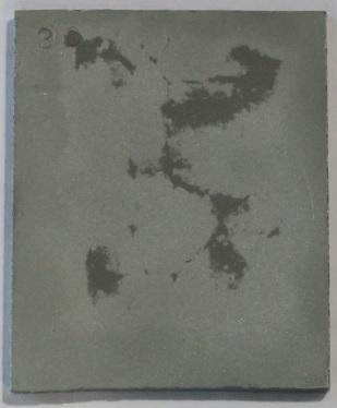
22 Table 7: B-HDG Intermetallic Layer Thickness Values Layer B-HDG I B-HDG II AVG STDEV AVG STDEV Eta Zeta Delta Gamma Average B-HDG Sample Intermetallic Layer Thicknesses 6 Thickness, mils Eta Zeta Delta Gamma 1 0 B-HDG I B-HDG II Figure 19: Average B-HDG Coating Intermetallic Layer Thicknesses Prior to testing, test articles were tested for the presence of chromates on the surface. Tests were completed using Chromate Check swabs. These swabs produce an instant, non-destructive test result. The swab was rubbed on the surface of the test article, and its color observed. No color change indicates no chromates are present. The same swab was then rubbed on a confirmation card that would cause it to turn purple, indicating that the test was valid. In the event the swab did not change color when rubbed on the confirmation card, the test would be declared invalid and a second test would be conducted with a new swab. Figure 20 and Figure 21 show representative images of the negative test results and the positive test confirmation. No chromates were found on the C-HDG Type I or II and the B-HDG Type II Samples. However, chromates were detected on the B-HDG Type I samples. The chromate process is typically a means to protect samples while in storage (nominally 6-weeks). Due to the accelerated nature of the GMW14872 test, chromates were no longer detectable after one cycle. After the first cycle, the B-HDG Type I and Type II samples were similar in appearance. The observations suggested that the initially detectable chromates would not influence the results. 17

 was used to remove some of the galvanized coating prior to testing.")
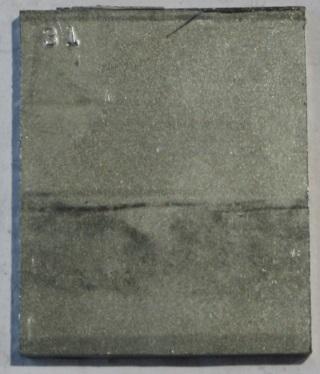
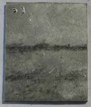
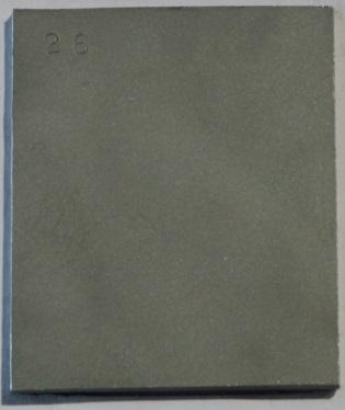
23 Figure 20. Negative Chromate Present Test Figure 21. Confirmation of Test Accuracy Pre-Conditioned Samples Various mechanical and chemical means were considered to remove a portion of galvanized coating before exposure inside the simulated corrosive environment. Each of the methods resulted in an uneven final thickness (perhaps due in part to uneven initial conditions). Based on preliminary testing, abrasive blasting with fine grit aluminum oxide media ( grit) was used to remove some of the galvanized coating prior to testing. Each coupon was blasted using the same pattern (horizontally followed by vertically in a checkerboard like pattern). After each evolution of blasting, five (5) dry film thickness measurements were performed. This process was repeated until less than 1 mil was achieved on at least two (2) of the five (5) locations. Each blasting pass required approximately one (1) minute, after which the sample was not noticeably warm. Therefore, we do not believe that the time or temperature was sufficient for any alloying effect. Figure 22 shows the average, minimum and maximum dry film thickness measurements taken on the pre-conditioned samples. The resulting surfaces had uneven coating thickness between 0.04 and 6.4 mils. Figure 23 shows examples of the pre-conditioned samples. The B-HDG samples tended to have more steel/alloy layer exposed than the C-HDG samples. Table 8 shows the number of individual measurements falling into various ranges. At each inspection period coating thickness was again measured at each location to try to attempt to detect changes in behavior associated with the interface between the zinc and steel. 18


24 Coating Thickness, mils Zinc Thickness Prior to Exposure B-HDG I B-HDG II C-HDG I C-HDG II Guardrail Type Figure 22: Average, Min and Max DFT on Pre-Conditioned Samples Figure 23: Representative Pre-Conditioned Samples (B-HDG left, C-HDG right) Table 8: Range of Reduced Thicknesses Thickness, mils B-HDG I B-HDG II C-HDG I C-HDG II < x < x < x > x > Test Chamber Process Control The GMW14872 test exposure conditions are verified by monitoring mass loss of steel coupons. Target ranges for the number of cycles necessary to meet the required mass loss ranges are listed 19
25 in the specification. To ensure proper exposure test conditions, duplicate 1-inch x 2-inch x inch cold-rolled steel uncoated mass loss coupons (purchased from ACT Test Panels, stated to meet the requirements of GMW14872) were exposed and removed every 20 cycles to track overall corrosion progression. Additional duplicate coupon sets were removed and replaced every 10 cycles to track interim corrosion. Figure 24 shows the iterative 10-cycle steel mass loss data and Figure 25 shows the cumulative target steel mass loss range (in green) and the data measured. The elevated mass loss between cycles 40 and 50 may be due to increased ambient time (without solution spray) during repairs to the test chamber. The cumulative mass loss data demonstrate that the test has been performed in accordance with the requirements. Steel Mass Loss, g Cycle Iterative Steel Mass Loss Coupon Data Upper Target Loss Lower Target Loss Cycles Figure 24: 10-Cycle Iterative Steel Mass Loss Data for Test Control Coupons 25 Cumulative Steel Mass Loss Coupon Data Steel Mass Loss, g # of Cycles Expected Range 20 Cycles 40 Cycles 60 Cycles 80 Cycles 100 Cycles 120 Cycles Figure 25: Cumulative Steel Mass Loss Data for Test Control Coupons 20


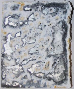
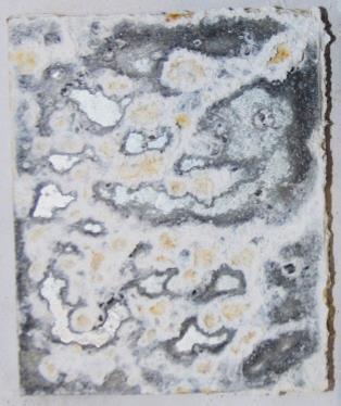
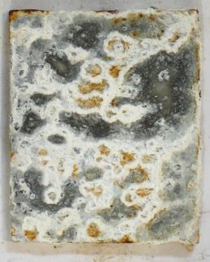
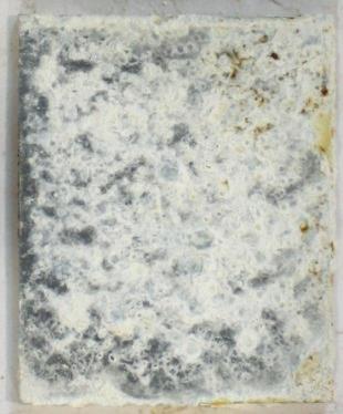
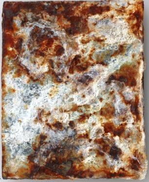
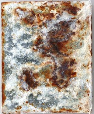
26 Exposed Guardrail Corrosion Performance Overall Visual Analysis Figure 26 through Figure 29 show the conditions of the B-HDG spliced and straight guardrails after 120-cycles of exposure in the GMW14872 chamber. All surfaces of the B-HDG guardrails exhibited white zinc corrosion product. Additionally, following 120-cycles of exposure, spots of red rust were observed scattered across each of the B-HDG samples. The red rust spots were initially observed during the 30-cycle inspection and progressed to encompass more of the guardrail surface throughout the duration of the test. The rusting seemed to begin at the bottom surface and progress toward the top surfaces. Less red rust was observed on the Type II (thicker) samples than on Type I (thinner) samples. B-HDG Type I Figure 26: Condition of B-HDG Type I Spliced Guardrail after 120-Cycles in GMW


27 B-HDG Type II Figure 27: Condition of B-HDG Type II Spliced Guardrail after 120-Cycles in GMW14872 B-HDG Type I Figure 28: Condition of B-HDG Type I Straight Guardrail after 120-Cycles in GMW


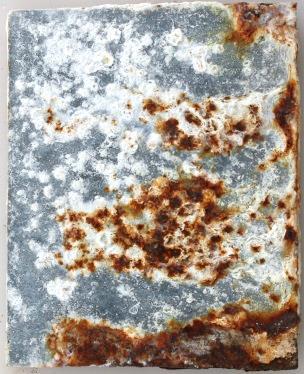
28 B-HDG Type II Figure 29: Condition of B-HDG Type II Straight Guardrail after 120-Cycles in GMW14872 Aside from at edges and mated interfaces, the red rust does not appear to be substrate corrosion, but likely results from oxidation of iron in the intermetallic layers [10]. The scattered nature of the observed red rust may be the result of the thinner grain boundaries of the spangle (observed pre-exposure and shown in Figure 30) [11-12]. The center areas of the spangle have thicker coating in which the eta layer would last longer. Figure 31 shows an example of the red rust observed and the condition after corrosion product removal with glass bead media. No measurable steel pitting is evident. Pitting of the steel substrate was observed on areas of the factory edges at the splice interface and at the interfaces to the mounting posts. Less pitting was observed on the Type II (thicker) samples than on Type I (thinner) samples. Figure 30: Spangle on B-HDG Samples 23


 samples than on Type I (thinner) samples.")

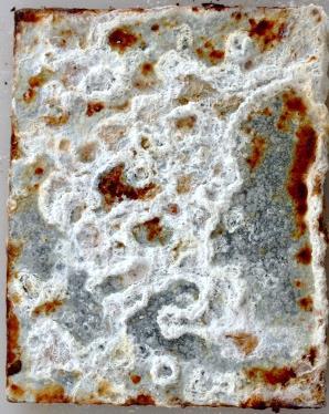
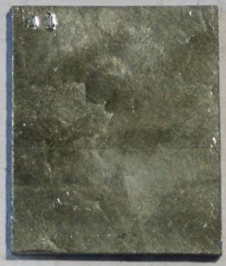
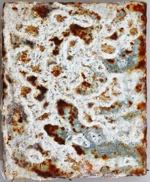
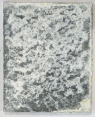
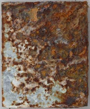
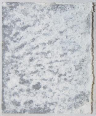
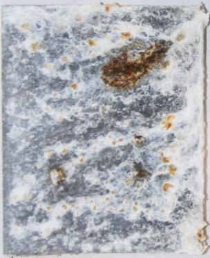
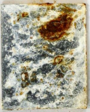
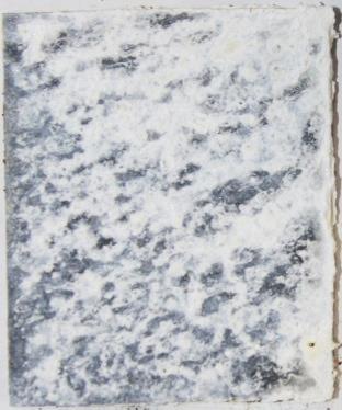
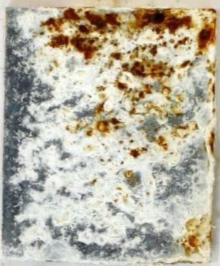
29 Figure 31: Example of Red Rust Forming from Iron in the Iron-Zinc Phases Figure 32 through Figure 35 show the condition of the spliced and straight C-HDG guardrail samples. All surfaces of the C-HDG guardrails exhibited white zinc corrosion product. Additionally, following 120-cycles of exposure, varying degrees of red rust were observed on each of the C-HDG samples. Less rusting was observed on the Type II (thicker) samples than on Type I (thinner) samples. Red rusting associated with steel substrate corrosion and pitting was observed at areas on the factory edges at the splice interface and at the interfaces to the mounting posts. Furthermore, significant rust-through was observed on the bottom surface of the Type I guardrails. C-HDG Type I Figure 32: Condition of C-HDG Type I Spliced Guardrail after 120-Cycles in GMW


30 C-HDG Type II Figure 33: Condition of C-HDG Type II Spliced Guardrail after 120-Cycles in GMW14872 C-HDGI Type I Figure 34: Condition of C-HDG Type I Straight Guardrail after 120-Cycles in GMW


31 C-HDG Type II Figure 35: Condition of C-HDG Type II Straight Guardrail after 120-Cycles in GMW14872 Figure 36 and Figure 37 more closely demonstrate the corrosion observed at the factory edges of each of the spliced guardrails. The Type I samples generally exhibited more substrate corrosion than the Type II samples for both coating types. The C-HDG samples exhibited similar corrosion to the B-HDG samples, despite the fact that these edges are uncoated. While the coating thickness on the edges of the B-HDG samples was not specifically measured prior to testing, the samples were carefully handled and there was no remarkable evidence of damage prior to testing. 26


32 B-HDG Type I B-HDG Type II Figure 36: Edge Corrosion on B-HDG Spliced Samples 27


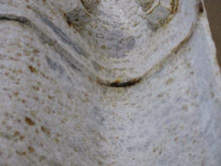
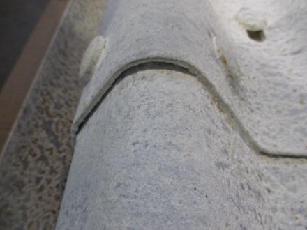
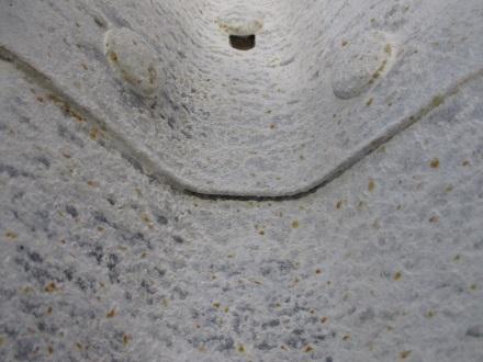
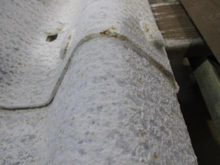
33 C-HDG Type I C-HDG Type II Figure 37: Edge Corrosion on C-HDG Spliced Samples Splice Interface Figure 38 and Figure 39 show the conditions of the mated surfaces of the spliced guardrails after exposure. There was less visible surface rusting on the mating surface of the Type II samples than Type I samples for both galvanizing processes. The C-HDG samples had less visible surface rusting than the B-HDG samples. 28


.")
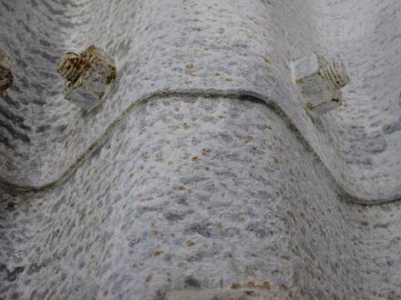
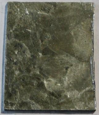
34 Each of the mated surfaces was glass bead blasted to evaluate metal loss by measuring pit depths. There were deeper pits on the Type I samples than the Type II samples. However, the C-HDG samples and B-HDG samples had comparable depth of attack for samples of the same Type. This suggests that the visible surface rusting on the B-HDG samples looks more severe due to iron from the intermetallic layers. Figure 40 shows examples of metal loss on the respective Type I samples. Due the curvature of the samples, depth of attack was difficult to measure, but attempts were made with a pit depth gauge (measurements are approximate). Figure 41 shows a cumulative distribution of measurable depth of attack for each guardrail type. B-HDG I B-HDG II Figure 38: Condition at Splice Interface of B-HDG Samples 29


35 C-HDG I C-HDG II Figure 39: Condition at Splice Interface of C-HDG Samples B-HDG I C-HDG I Figure 40: Examples of Metal Loss on Mating Surface of Spliced Samples 30


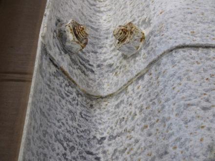
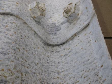
36 Probability of Occurrence Guardrail Depth of Attack Depth, mils B-HD1 B-HD2 C-HD1 C-HD2 Figure 41: Depth of Attack Evaluated at Mated Surfaces Figure 42 and Figure 43 show representative condition of the guardrail at a splice bolt interface for B-HDG and C-HDG samples. The B-HDG samples had less red rust and pitting at interfaces to the splice bolts than C-HDG samples. Depth of attack was most severe on the C-HDG I sample, but it was not enough to compromise the structural integrity of the guardrail. B-HDG Type I B-HDG Type II Figure 42: Representative Condition of Guardrail/Splice Bolt Interface on B-HDG Samples 31


 minutes per side to remove the corrosion product.")
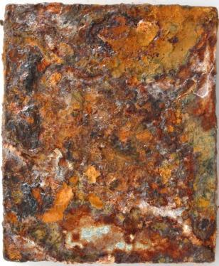
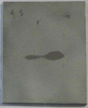
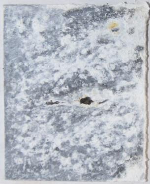
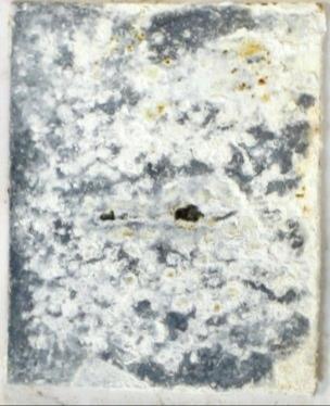
37 C-HDG Type I C-HDG Type II Figure 43: Representative Condition of Guardrail/Splice Bolt Interface on C-HDG Samples ASTM A90 Coupon Performance The 2-in x 2.5-in coupons exhibited similar corrosion as their guardrail counterparts, with the C- HDG Type I samples exhibiting the most severe corrosion after 120-cycles. The B-HDG samples further demonstrate the effect of the spangle, with corrosion initially appearing in the area of the grain boundaries before progressing. Figure 44 and Figure 45 show representative photos of one coupon set at each inspection interval. At each inspection interval, one replicate coupon for each material was removed, blasted with glass bead media to remove corrosion product, and sent for ASTM A90 analysis. The blasting process took approximately two (2) minutes per side to remove the corrosion product. To ensure that no coating was removed during this process, an unexposed coupon of both B-HDG and C- HDG was blasted in one (1) minute intervals up to a maximum of five (5) minutes, and weighed each time. At most, only grams (.007 mils) and grams (0.009 mils) were removed for B-HDG and C-HDG, respectively, which was considered negligible. 32

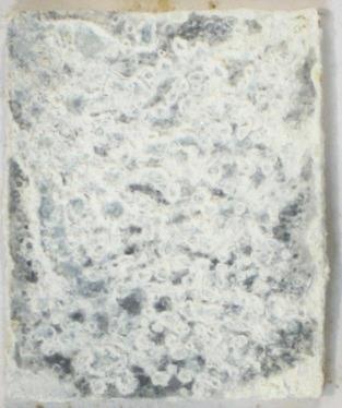
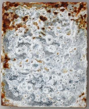
38 Pre-Exposure 30-Cycles 60-Cycles 120-Cycles B-HDG Type I B-HDG Type II Figure 44: Representative B-HDG Coupons throughout the Test Period Pre-Exposure 30-Cycles 60-Cycles 120-Cycles C-HDG Type I C-HDG Type II Figure 45: Representative C-HDG Coupons throughout the Test Period 33
39 Figure 46 shows the estimated remaining coating thicknesses based on the coating mass results (these calculated coating thickness values assume uniform coating thickness across the sample and are therefore considered only an estimate for comparison purposes.). These data support the microscopy observations, in which little to no coating was visible. Figure 47 and Figure 48 show representative examples of microscopy observations after 120-cycles as compared to preexposure. SEM images of all materials after 60 cycles are included in Appendix A. Coating Thickness - ASTM A90 Coupons Coating Thickness, mils B-HDG I B-HDG II C-HDG I C-HDG II Guardrail Type Pre-Exposure 30 Cycles 60 Cycles 90 Cycles 120 Cycles Figure 46: Calculated Coating Thickness from ASTM A90 Coupon Samples Figure 47: Microscopy of C-HDG Type I Pre-Exposure (Left) and After 120-Cycles (Right) 34

40 Figure 48: Microscopy of B-HDG Type II Pre-Exposure (Left) and After 120-Cycles (Right) Figure 49 shows the average percent of red rust estimated visually on the coupon surfaces at each of the evaluation periods. The B-HDG samples exhibited 1-10% surface rust during the early stages of exposure. However, after the final evaluation and sample teardown that most of the observed rust was superficial rust and not the result of measurable substrate corrosion. Visible rust on the C-HDG Type I samples does appear to be the result of substrate corrosion. 100 Estimated Percentage of Red Rust Visible on Coupon Surface Percent Red Rust on Coupon Surface Cycles 60-Cycles 90-Cycles 120-Cycles B-HDG I B-HDG II C-HDG I C-HDG II Figure 49: Estimated Surface Area Percentage Exhibiting Red Rust Pre-Conditioned Coupon Performance Figure 50 and Figure 51 show representative photos of the pre-conditioned samples before exposure and at the 30, 60, and 120-cycle evaluations. The non-uniform removal of the galvanized coating makes it challenging to draw meaningful conclusions from the data. However, their appearance is consistent with the other observations in this testing. 35
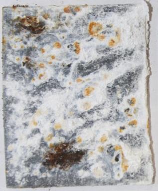
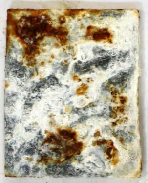
41 Pre-Exposure 30-Cycles 60-Cycles 120-Cycles B-HDG Type I B-HDG Type II Figure 50: Representative Pre-Conditioned B-HDG Coupons throughout the Test Period Pre-Exposure 30-Cycles 60-Cycles 120-Cycles C-HDG Type I C-HDG Type II Figure 51: Representative Pre-Conditioned C-HDG Coupons throughout the Test Period 36
42 Zinc Mass Loss After the 60-cycle evaluation, 99.9% pure zinc coupons (1-in x 2-in x.0625-in, purchased from the Metal Samples Company) were exposed with the guardrail samples to determine the corrosion rate of pure zinc in the GMW14872 environment. Figure 52 shows the estimated coating thickness loss calculated from the zinc coupon mass loss. If the linear relationship continues, approximately 3.7 mils (calculated to be approximately 2.2 oz/ft 2 ) mils would be lost after 120-cycles. This corroborates what was observed on the C-HDG I guardrail and coupons samples, as coating weights on these samples were measured to be close to 2 oz/ft 2 and were the only samples to exhibit significant substrate corrosion on the boldly exposed, unmated surfaces. Figure 53 shows the estimated average zinc loss based on measurements taken from the ASTM A90 samples and SEM images. The ASTM A90 coating masses were compared for preexposure and after 30-cycles of exposure. Data for the longer exposed samples had increased scatter, likely due to increased steel corrosion product present. The SEM measurements were taken pre-exposure and at 60 cycles. Note that the SEM observations are highly localized, thus considerable variability is expected. While there is not enough data to generate an adequate statistical comparison, the observed loss rate observations for the galvanized guardrail seem consistent with the corrosion rate of pure zinc. 1.4 Cumulative Zinc Coupon Mass Loss Data Zinc Thickness, mils y = x Cycles Replicate 1 Replicate 2 Figure 52: Zinc Coating Loss calculated from Coupon Mass Loss 37
43 Estimated Average Zinc Loss Rate, mils/cycle B-HDG I B-HDG II C-HDG I C-HDG II Figure 53: Estimated Average Zinc Loss Rate as a Function of Measurement Method Corrosion Acceleration A90 SEM Pure Zinc Coupons Figure 54 presents a chart developed by American Galvanizers Association to predict the time to first maintenance for a given thickness of zinc in any of five generic environments [13]. The criteria used for first maintenance is 5% surface rusting. The visible rusting data gathered over the 120-cycle period of GMW14872 testing presented in Figure 49 can be used in conjunction with the curves in Figure 54 to estimate an acceleration factor. Five percent rusting occurred on the C-HDG Type I sample (2 mils thick) between 60 and 90 cycles of testing and is predicted to occur at approximately 35 years in an industrial environment and 65 years in a rural environment. Five percent rusting occurred on the B-HDG Type I sample (3.5 mils thick) between 90 and 120 cycles of testing and is predicted to occur at approximately 65 years in an industrial environment. More detailed data is necessary to establish correlations between the cyclic corrosion test and specific natural environments, however the observations suggest a trend exists. 38
44 Figure 54: Time to First Maintenance Prediction (American Galvanizers Association [13]) 39
45 Conclusions The following conclusions are made based on the results of this study: The test results demonstrate a clear benefit of increased galvanized coating thickness for corrosion resistance, regardless of the galvanizing process. Crevices such as the splice area and areas under fasteners present the most significant corrosion problem for a guardrail. o The splice interface of B-HDG and C-HDG exhibited measurable pitting which was comparable for the two processes. An order of magnitude increase in pit depth was observed for the thinner (Type I) coating for both galvanizing processes. o The difference in the coupon data versus that of the 1-meter samples demonstrates the importance of testing with full-scale test pieces which incorporate realistic configuration details such as crevices. The test results do not clearly demonstrate the superiority of one hot dip galvanizing process over the other. However, they do demonstrate different characteristics of batch hot dip and continuous hot dip galvanizing. o Bold-faced surfaces of the B-HDG (Type I and Type II) and C-HDG Type II samples did not exhibit substrate corrosion (i.e., section loss) after 120-cycles in GMW B-HDG (Type I and Type II) samples exhibited rust staining, possibly due to corrosion of the iron in the intermetallic layers. C-HDG I samples exhibited substrate corrosion after 120-cycles in GMW A direct comparison to B-HDG Type I is not applicable due to the significant difference in thickness. o Guardrail edges of C-HDG samples, despite being uncoated, corroded at similar rates and to similar severities as edges on the B-HDG samples. Edges of Type I samples exhibited more steel corrosion than the edges of Type II samples, regardless of galvanizing process. Non-destructive thickness testing was not an effective means of evaluating galvanized coating loss in the accelerated test. 40
46 Recommendations The following recommendations are made based on the results of this study: Corroborate these laboratory data with observations of guardrails exposed in a service environment. Service exposure data would help confirm: o Relative performance of Type I and Type II guardrails o Relative performance of B-HDG and C-HDG guardrails o Relative magnitude of corrosion in crevices versus boldly exposed surfaces Establish a relationship between accelerated corrosion tests and highway environment corrosivity. Such a relationship would help specifiers develop guidelines for guardrail material selection. The guidelines would need to consider the environmental corrosivity, desired service life, and material performance. Evaluate the effectiveness of alternative treatments to mitigate crevice corrosion in the splice joint. In addition to the corrosion benefits, the cost effectiveness and manufacturability of alternatives should be considered. Alternatives may include a dielectric coating, double-dip coating of zinc on these junctions, thermal spray of additional zinc, or insertion of a sheet of zinc. 41
47 References [1] General Motors Worldwide Engineering Standards, GMW14872 Cyclic Corrosion Laboratory Test, March [2] American Association of State Highway and Transportation Officials designation: M Corrugated sheet steel beams for Highway Guardrail [3] Comparison of Methods Used to Produce Hot-Dipped Galvanized W-Beam Guardrail, R. Till and C. Davis, January 1998, Michigan Department of Transportation Research Project No. R [4] Accelerated Corrosion Tests in the Automotive Industry: A Comparison of the Performance Towards Cosmetic Corrosion, N. LeBozec, N. Blandin and D. Thierry, 2008, Materials and Corrosion, 59, No. 11, [5] Cramer, S. D., & Covino, B. S. (2005). ASM Handbook, Volume 13B, Corrosion: Materials. Materials Park: ASM International. [6] Knotkova, D., Kreislova, K., & Dean, S. W. (2010). International Atmospheric Exposure Program: Summary of Results. Bay Shore: ASTM International. [7] Repp, J., Ault, J. P., & Handsy, I. C. (2009). Evaluation Of Army Materials Of Manufacture In The Hawaiian Islands Lessons Learned DoD Corrosion Conference, (pp. 1-12). Washington, D.C. [8] Terrence R. Giles, Michelle Lerminez and Sabrinia Smith, Examination of the Effects of Test Piece Spacing in ASTM B Neutral SaltSpray and General Motors 9540P 2003 SAE World Congress, SAE International. [9] American Galvanizers Association, The HDG Coating, [10] American Galvanizers Association, 2004, Hot-Dip Galvanizing for Corrosion Prevention A Guide to Specifying and Inspecting Hot-Dip Galvanized Reinforcing Steel, 20To%20Rebar% pdf, Page 12. [11] GalvInfo Center, 2011, The Spangle on Hot-Dip Galvanized Steel Sheet, [12] Singh, A.K, Jha, G., and Chakrabarti, S., 2003, Spangle Formation on Hot-Dip Galvanized Stele Sheet and its Effects on Corrosion-Resistant Properties, NACE Corrosion Journal, Vol. 59, No. 2, Page
48 [13] American Galvanizers Association, 2010, General Hot-Dip Galvanizing vs. Continuous Sheet Galvanizing, Dip_Galvanizing_vs_Continuous_Sheet_Galvanizing.pdf 43
49 Appendix A- SEM/EDX Baseline Analysis 44
 LABORATORY ANALYSIS REPORT 26 Aug 2014 JOB NUMBER P0EMR948 PO NUMBER NJ-126 for Rich")
 Reviewed by: Juergen Scherer, Ph.D. Specialist (Tel. 952-641-1241; jscherer@eag.")
50 ISO Testing Cert. # SCANNING ELECTRON MICROSCOPY (SEM) LABORATORY ANALYSIS REPORT 26 Aug 2014 JOB NUMBER P0EMR948 PO NUMBER NJ-126 for Rich Gianforcaro Elzly Technology Corporation Prepared by: Lori LaVanier Auger/SEM Specialist (Tel ; Reviewed by: Juergen Scherer, Ph.D. Specialist (Tel ; Evans Analytical Group Lake Drive East Chanhassen, MN USA Fax Page 1 / 24
51 SEM ANALYSIS REPORT Requester: Rich Gianforcaro Job Number: P0EMR948 Analysis Date: 26 Aug 2014 Purpose To measure layer thickness and identify elemental composition of layers on polished crosssections of galvanized steel samples B, B, C and C Results and Interpretations SEM images were taken to document the EDX analysis locations and also used for measurement overlays of layer thicknesses. Weight percentages were calculated for all spectra and are summarized in the Excel table. Note that Au/Pd and (materials used to coat the sample for conductivity) were excluded from the calculations. Two locations an each sample were imaged for layer thickness estimations, and also analyzed for composition. BSE images were taken to show contrast related to atomic number (with heavier elements showing brighter contrast). Note that EDX analysis of the Gamma layer on samples B and B likely contains signal from he adjacent layers since this layer is less than 2um thick. SEM/EDS Instrument Conditions Instrument: Electron Beam Conditions: Hitachi Variable Pressure SEM Model S-3400N 20kV, 0º sample tilt The samples were coated previously with Au/Pd. Samples B and B were coated with at EAG-MN for additional conductivity for best imaging. Unless specifically stated otherwise elsewhere in this report the uncertainty of dimensional SEM measurements is about ±10% (providing an estimated level of confidence of 95% using a coverage factor k = 2). Uncertainty estimates are calculated in accordance with the ISO Guide to the Expression of Uncertainty in Measurement. EDS should be considered a semi-quantitative analysis technique. Concentrations provided can typically be reproduced for major constituents of homogeneous samples to better than ±10%. However, the concentrations provided could have a bias when compared to certified reference materials (e.g. NIST standard reference materials). This bias could be corrected by calibrating the sensitivity factors against such certified reference materials (if available). After reviewing this report, you may assess our services using an electronic service evaluation form. This can be done by clicking on the link below, or by pasting it into your internet browser. Your comments and suggestions allow us to determine how to better serve you in the future. This analysis report should not be reproduced except in full, without the written approval of EAG. Evans Analytical Group Lake Drive East Chanhassen, MN USA Fax Page 2 / 24

52 SEM Analysis Report Job Number: P0EMR Client: Rich Gianforcaro Company: Elzly Technology Corporation Figure 1 Mag = 30X C-HDG I Au/Pd coated Figure 2 Mag = 30X C-HDG I BSE image Evans Analytical Group Lake Drive East Chanhassen, MN USA Fax Page 3 / 24


53 SEM Analysis Report Job Number: P0EMR Client: Rich Gianforcaro Company: Elzly Technology Corporation Figure 3 Mag = 500X C-HDG I Location 1 Figure 4 Mag = 500X C-HDG I Location 1 BSE image Evans Analytical Group Lake Drive East Chanhassen, MN USA Fax Page 4 / 24

54 SEM Analysis Report Job Number: P0EMR Client: Rich Gianforcaro Company: Elzly Technology Corporation Figure 5 Mag = 250X C-HDG I Location 1 Spectrum 1 Figure 6 O C Al Si Au Au Au Au Au Full Scale cts Cursor: kev Mn Spectrum 2 C-HDG I Location 1 Mn C Al Mn Full Scale cts Cursor: (2398 cts) kev Evans Analytical Group Lake Drive East Chanhassen, MN USA Fax Page 5 / 24


55 SEM Analysis Report Job Number: P0EMR Client: Rich Gianforcaro Company: Elzly Technology Corporation Figure 7 Mag = 500X C-HDG I Location 2 Figure 8 Mag = 500X C-HDG I Location 2 BSE image Evans Analytical Group Lake Drive East Chanhassen, MN USA Fax Page 6 / 24
 kev Mn Au Au Spectrum 2 C-HDG I Location 3 Mn C Al Mn 0 1 2 3 4 5 6 7 8 9 10 Full Scale 9650 cts Cursor: 0.")
56 SEM Analysis Report Job Number: P0EMR Client: Rich Gianforcaro Company: Elzly Technology Corporation Figure 9 Mag = 500X C-HDG I Location 3 Spectrum 1 Figure 10 O Al Si Au Pd C Au Au Pd Pd Full Scale cts Cursor: (2369 cts) kev Mn Au Au Spectrum 2 C-HDG I Location 3 Mn C Al Mn Full Scale 9650 cts Cursor: (2300 cts) kev Evans Analytical Group Lake Drive East Chanhassen, MN USA Fax Page 7 / 24


57 SEM Analysis Report Job Number: P0EMR Client: Rich Gianforcaro Company: Elzly Technology Corporation Figure 11 Mag = 300X C-HDG II Location 1 Figure 12 Mag = 300X C-HDG II Location 2 Evans Analytical Group Lake Drive East Chanhassen, MN USA Fax Page 8 / 24
 kev Mn Au Au Spectrum 2 C-HDG II Location 1 Mn C Al Mn 0 1 2 3 4 5 6 7 8 9 10 Full Scale 9627 cts Cursor: -0.")
58 SEM Analysis Report Job Number: P0EMR Client: Rich Gianforcaro Company: Elzly Technology Corporation Figure 13 Mag = 300X C-HDG II Location 1 Spectrum 1 Figure 14 O Al Si Au C Au Au Pd Pd Full Scale cts Cursor: (273 cts) kev Mn Au Au Spectrum 2 C-HDG II Location 1 Mn C Al Mn Full Scale 9627 cts Cursor: (300 cts) kev Evans Analytical Group Lake Drive East Chanhassen, MN USA Fax Page 9 / 24
 kev Mn Au Au Spectrum 2 C-HDG II Location 2 Mn C Al Si Mn 0 1 2 3 4 5 6 7 8 9 10 Full Scale 9202 cts Cursor: -0.")
59 SEM Analysis Report Job Number: P0EMR Client: Rich Gianforcaro Company: Elzly Technology Corporation Figure 15 Mag = 300X C-HDG II Location 2 Spectrum 1 Figure 16 O Al Si Au Cl Pd C Au Au Cl Pd Full Scale cts Cursor: (301 cts) kev Mn Au Au Spectrum 2 C-HDG II Location 2 Mn C Al Si Mn Full Scale 9202 cts Cursor: (311 cts) kev Evans Analytical Group Lake Drive East Chanhassen, MN USA Fax Page 10 / 24

60 SEM Analysis Report Job Number: P0EMR Client: Rich Gianforcaro Company: Elzly Technology Corporation Figure 17 Mag = 100X B-HDG I coated at EAG- MN Figure 18 Mag = 100X B-HDG I BSE image coated at EAG- MN Evans Analytical Group Lake Drive East Chanhassen, MN USA Fax Page 11 / 24


61 SEM Analysis Report Job Number: P0EMR948 Client: Rich Gianforcaro Company: Elzly Technology Corporation Figure 19 Mag = 800X B-HDG I coated at EAGMN Figure 20 Mag = 800X B-HDG I BSE image coated at EAGMN Evans Analytical Group Lake Drive East Chanhassen, MN USA Fax Page 12 / 24


62 SEM Analysis Report Job Number: P0EMR Client: Rich Gianforcaro Company: Elzly Technology Corporation Figure 21 Mag = 900X B-HDG I Second Location coated at EAG- MN Figure 22 Mag = 3500X B-HDG I Second Location Higher Magnification of Gamma coated at EAG- MN Evans Analytical Group Lake Drive East Chanhassen, MN USA Fax Page 13 / 24
 kev Spectrum 2 B-HDG I C O Al Si 0 1 2 3 4 5 6 7 8 9 10 Full Scale 16595 cts Cursor: -0.")
63 SEM Analysis Report Job Number: P0EMR Client: Rich Gianforcaro Company: Elzly Technology Corporation Figure 23 Mag = 950X B-HDG I coated at EAG- MN Spectrum 1 Figure 24 C O Full Scale cts Cursor: (312 cts) kev Spectrum 2 B-HDG I C O Al Si Full Scale cts Cursor: (298 cts) kev Spectrum 3 coated at EAG- MN C O Al Full Scale cts Cursor: (285 cts) kev Evans Analytical Group Lake Drive East Chanhassen, MN USA Fax Page 14 / 24
 kev Mn C O Al Si Mn 0 1 2 3 4 5 6 7 8 9 10 Full Scale 9726 cts Cursor: -0.")
64 SEM Analysis Report Job Number: P0EMR Client: Rich Gianforcaro Company: Elzly Technology Corporation Figure 25 Mag = 5000X B-HDG I coated at EAG- MN Spectrum 1 Figure 26 C O Al Full Scale cts Cursor: (285 cts) kev Mn C O Al Si Mn Full Scale 9726 cts Cursor: (293 cts) kev Mn Spectrum 2 B-HDG I *note that Gamma region may contain signal from adjacent regions coated at EAG- MN Evans Analytical Group Lake Drive East Chanhassen, MN USA Fax Page 15 / 24
 kev Spectrum 2 B-HDG I C O Al Si Location 2 0 1 2 3 4 5 6 7 8 9 10 Full Scale 15559 cts Cursor: -0.")
65 SEM Analysis Report Job Number: P0EMR Client: Rich Gianforcaro Company: Elzly Technology Corporation Figure 27 Mag = 900X B-HDG I Location 2 Spectrum 1 Figure 28 C O Full Scale cts Cursor: (298 cts) kev Spectrum 2 B-HDG I C O Al Si Location Full Scale cts Cursor: (284 cts) kev Spectrum 3 C O Al Full Scale cts Cursor: (273 cts) kev Evans Analytical Group Lake Drive East Chanhassen, MN USA Fax Page 16 / 24
 kev Spectrum 2 B-HDG I Mn Location 2 Mn Al Si C Mn 0 1 2 3 4 5 6 7 8 9 10 Full Scale 7905 cts Cursor: -0.")
66 SEM Analysis Report Job Number: P0EMR Client: Rich Gianforcaro Company: Elzly Technology Corporation Figure 29 Mag = 5000X B-HDG I Location 2 Spectrum 1 Figure 30 C O Al Full Scale cts Cursor: (268 cts) kev Spectrum 2 B-HDG I Mn Location 2 Mn Al Si C Mn Full Scale 7905 cts Cursor: (282 cts) kev Evans Analytical Group Lake Drive East Chanhassen, MN USA Fax Page 17 / 24


67 SEM Analysis Report Job Number: P0EMR Client: Rich Gianforcaro Company: Elzly Technology Corporation Figure 31 Mag = 500X B-HDG II Location 1 coated at EAG- MN Figure 32 Mag = 2500X B-HDG II Location 1 Evans Analytical Group Lake Drive East Chanhassen, MN USA Fax Page 18 / 24


68 SEM Analysis Report Job Number: P0EMR Client: Rich Gianforcaro Company: Elzly Technology Corporation Figure 33 Mag = 500X B-HDG II Location 2 Figure 34 Mag = 2500X B-HDG II Location 2 Evans Analytical Group Lake Drive East Chanhassen, MN USA Fax Page 19 / 24
 kev Spectrum 2 B-HDG II Location 1 C O Al 0 1 2 3 4 5 6 7 8 9 10 Full Scale 15674 cts Cursor: -0.")
69 SEM Analysis Report Job Number: P0EMR Client: Rich Gianforcaro Company: Elzly Technology Corporation Figure 35 Mag = 500X B-HDG II Location 1 Spectrum 1 Figure 36 C O Full Scale cts Cursor: (289 cts) kev Spectrum 2 B-HDG II Location 1 C O Al Full Scale cts Cursor: (290 cts) kev Spectrum 3 C O Full Scale cts Cursor: (287 cts) kev Evans Analytical Group Lake Drive East Chanhassen, MN USA Fax Page 20 / 24
 kev Spectrum 2 B-HDG II Location 1 C O Al 0 1 2 3 4 5 6 7 8 9 10 Full Scale 16374 cts Cursor: -0.")
70 SEM Analysis Report Job Number: P0EMR Client: Rich Gianforcaro Company: Elzly Technology Corporation Figure 37 Mag = 2500X B-HDG II Location 1 Spectrum 1 Figure 38 C O Al Full Scale cts Cursor: (295 cts) kev Spectrum 2 B-HDG II Location 1 C O Al Full Scale cts Cursor: (286 cts) kev Evans Analytical Group Lake Drive East Chanhassen, MN USA Fax Page 21 / 24
 kev Spectrum 2 B-HDG II Location 2 C O Al 0 1 2 3 4 5 6 7 8 9 10 Full Scale 15448 cts Cursor: -0.")
71 SEM Analysis Report Job Number: P0EMR Client: Rich Gianforcaro Company: Elzly Technology Corporation Figure 39 Mag = 500X B-HDG II Location 2 Spectrum 1 Figure 40 Al C O Full Scale cts Cursor: (278 cts) kev Spectrum 2 B-HDG II Location 2 C O Al Full Scale cts Cursor: (274 cts) kev Spectrum 3 C O Full Scale cts Cursor: (274 cts) kev Evans Analytical Group Lake Drive East Chanhassen, MN USA Fax Page 22 / 24
 kev Spectrum 2 B-HDG II Location 2 Mn Mn C O Mn 0 1 2 3 4 5 6 7 8 9 10 Full Scale 12615 cts Cursor: -0.")
72 SEM Analysis Report Job Number: P0EMR Client: Rich Gianforcaro Company: Elzly Technology Corporation Figure 41 Mag = 2500X B-HDG II Location 2 Spectrum 1 Figure 42 C O Full Scale cts Cursor: (271 cts) kev Spectrum 2 B-HDG II Location 2 Mn Mn C O Mn Full Scale cts Cursor: (270 cts) kev Evans Analytical Group Lake Drive East Chanhassen, MN USA Fax Page 23 / 24
73 EAG-MN P0EMR948 All results in weight% C O Al Si Mn C-HDG I Figure 5 Zinc Substrate C-HDG I Figure 9 Zinc Substrate C-HDG II Figure 13 Zinc Substrate C-HDG II Figure 15 Zinc Substrate B-HDG I Figure 23 Eta Zeta Delta B-HDG I Figure 25 Delta Gamma B-HDG I Figure 27 Eta Zeta Delta B-HDG I Figure 29 Delta Gamma B-HDG II Figure 35 Eta Zeta Delta B-HDG II Figure 37 Delta Gamma B-HDG II Figure 39 Eta Zeta Delta B-HDG II Figure 41 Delta Gamma Page 24 / 24
74 SEM Analysis Report Page 1 of 25 Job Number Y0EMA Jun 2014 Figure 1 Mag = X50 B-HDG I Figure 2 Mag = X50 B-HDG I Evans Analytical Group 104 Windsor Center, Suite 101 East Windsor, NJ USA Fax
75 SEM Analysis Report Page 2 of 25 Job Number Y0EMA Jun 2014 Figure 3 Mag = X1,000 B-HDG I Location 1 Figure 4 Mag = X1,000 B-HDG I Location 1 Evans Analytical Group 104 Windsor Center, Suite 101 East Windsor, NJ USA Fax

76 SEM Analysis Report Page 3 of 25 Job Number Y0EMA Jun 2014 Figure 5 Mag = X800 B-HDG I Location 2 Figure 6 Mag = X800 B-HDG I Location 2 Evans Analytical Group 104 Windsor Center, Suite 101 East Windsor, NJ USA Fax

77 SEM Analysis Report Page 4 of 25 Job Number Y0EMA Jun 2014 Figure 7 Mag = X50 B-HDG II Figure 8 Mag = X50 B-HDG II Evans Analytical Group 104 Windsor Center, Suite 101 East Windsor, NJ USA Fax


78 SEM Analysis Report Page 5 of 25 Job Number Y0EMA Jun 2014 Figure 9 Mag = X450 B-HDG II location 1 Figure 10 Mag = X450 B-HDG II location 1 Evans Analytical Group 104 Windsor Center, Suite 101 East Windsor, NJ USA Fax

79 SEM Analysis Report Page 6 of 25 Job Number Y0EMA Jun 2014 Figure 11 Mag = X450 B-HDG II location 2 Figure 12 Mag = X450 B-HDG II location 2 Evans Analytical Group 104 Windsor Center, Suite 101 East Windsor, NJ USA Fax
80 SEM Analysis Report Page 7 of 25 Job Number Y0EMA Jun 2014 Figure 13 Mag = X50 B-HDG I 60-Cycles Figure 14 Mag = X50 B-HDG I 60-Cycles Evans Analytical Group 104 Windsor Center, Suite 101 East Windsor, NJ USA Fax

81 SEM Analysis Report Page 8 of 25 Job Number Y0EMA Jun 2014 Figure 15 Mag = X800 B-HDG I 60-Cycles Location 1 corresponds to the left side of the area in Figure 13 Figure 16 Mag = X800 B-HDG I 60-Cycles Location 1 corresponds to the left side of the area in Figure 13 Evans Analytical Group 104 Windsor Center, Suite 101 East Windsor, NJ USA Fax
82 SEM Analysis Report Page 9 of 25 Job Number Y0EMA Jun 2014 Figure 17 Mag = X800 B-HDG I 60-Cycles Location 2 corresponds to the right side of the area in Figure 13 Figure 18 Mag = X800 B-HDG I 60-Cycles Location 2 corresponds to the right side of the area in Figure 13 Evans Analytical Group 104 Windsor Center, Suite 101 East Windsor, NJ USA Fax
83 SEM Analysis Report Page 10 of 25 Job Number Y0EMA Jun 2014 Figure 19 Mag = X3000 B-HDG I 60-Cycles Zoom in on Location 2 Element Weight% Weight% Atomic% Sigma C O Totals Figure 20 Quant Results Semi-quantitative results calculated from stored reference spectra Evans Analytical Group 104 Windsor Center, Suite 101 East Windsor, NJ USA Fax
84 SEM Analysis Report Page 11 of 25 Job Number Y0EMA Jun 2014 Figure 21 Mag = X50 B-HDG II 60-Cycles Figure 22 Mag = X50 B-HDG II 60-Cycles Evans Analytical Group 104 Windsor Center, Suite 101 East Windsor, NJ USA Fax
85 SEM Analysis Report Page 12 of 25 Job Number Y0EMA Jun 2014 Figure 23 Mag = X1000 B-HDG II 60-Cycles Location 1 Figure 24 Mag = X1000 B-HDG II 60-Cycles Location 1 Evans Analytical Group 104 Windsor Center, Suite 101 East Windsor, NJ USA Fax
86 SEM Analysis Report Page 13 of 25 Job Number Y0EMA Jun 2014 Figure 25 Mag = X1000 B-HDG II 60-Cycles Location 2 Figure 26 Mag = X1000 B-HDG II 60-Cycles Location 2 Evans Analytical Group 104 Windsor Center, Suite 101 East Windsor, NJ USA Fax
87 SEM Analysis Report Page 14 of 25 Job Number Y0EMA Jun 2014 Figure 27 Mag = X50 C-HDG I 60-Cycles Figure 28 Mag = X C-HDG I 60-Cycles Evans Analytical Group 104 Windsor Center, Suite 101 East Windsor, NJ USA Fax

88 SEM Analysis Report Page 15 of 25 Job Number Y0EMA Jun 2014 Figure 29 Mag = X1000 C-HDG I 60-Cycles Location 1 Zoom in on right side of Figure 28 Figure 30 Mag = X C-HDG I 60-Cycles Location 1 Evans Analytical Group 104 Windsor Center, Suite 101 East Windsor, NJ USA Fax
89 SEM Analysis Report Page 16 of 25 Job Number Y0EMA Jun 2014 Figure 31 Mag = X1,000 C-HDG I 60-Cycles Location 2 Figure 32 Mag = X1,000 C-HDG I 60-Cycles Location 2 Evans Analytical Group 104 Windsor Center, Suite 101 East Windsor, NJ USA Fax

90 SEM Analysis Report Page 17 of 25 Job Number Y0EMA Jun 2014 Figure 33 Mag = X50 C-HDG II 60-Cycles Figure 34 Mag = X50 C-HDG II 60-Cycles Evans Analytical Group 104 Windsor Center, Suite 101 East Windsor, NJ USA Fax

91 SEM Analysis Report Page 18 of 25 Job Number Y0EMA Jun 2014 Figure 35 Mag = X1000 C-HDG II 60-Cycles Location 1 zoom in on the area in Figure 27 Figure 36 Mag = X1000 C-HDG II 60-Cycles Location 1 zoom in on the area in Figure 27 Evans Analytical Group 104 Windsor Center, Suite 101 East Windsor, NJ USA Fax

92 SEM Analysis Report Page 19 of 25 Job Number Y0EMA Jun 2014 Figure 37 Mag = X1000 C-HDG II 60-Cycles Location 2 zoom in on the area in Figure 28 Figure 38 Mag = X1000 C-HDG II 60-Cycles Location 2 zoom in on the area in Figure 28 Evans Analytical Group 104 Windsor Center, Suite 101 East Windsor, NJ USA Fax
93 SEM Analysis Report Page 20 of 25 Job Number Y0EMA Jun 2014 Figure 39 Mag = X50 C-HDG I Figure 40 Mag = X50 C-HDG I Evans Analytical Group 104 Windsor Center, Suite 101 East Windsor, NJ USA Fax

94 SEM Analysis Report Page 21 of 25 Job Number Y0EMA Jun 2014 Figure 41 Mag = X700 C-HDG I Location 1 Figure 42 Mag = X700 C-HDG I Location 1 Evans Analytical Group 104 Windsor Center, Suite 101 East Windsor, NJ USA Fax

95 SEM Analysis Report Page 22 of 25 Job Number Y0EMA Jun 2014 Figure 43 Mag = X700 C-HDG I Location 2 Figure 44 Mag = X700 C-HDG I Location 2 Evans Analytical Group 104 Windsor Center, Suite 101 East Windsor, NJ USA Fax
96 SEM Analysis Report Page 23 of 25 Job Number Y0EMA Jun 2014 Figure 45 Mag = X50 C-HDG II Figure 46 Mag = X50 C-HDG II Evans Analytical Group 104 Windsor Center, Suite 101 East Windsor, NJ USA Fax

97 SEM Analysis Report Page 24 of 25 Job Number Y0EMA Jun 2014 Figure 47 Mag = X500 C-HDG II Location 1 Figure 48 Mag = X500 C-HDG II Location 1 Evans Analytical Group 104 Windsor Center, Suite 101 East Windsor, NJ USA Fax
Presented to: Prepared by:
 Final Report Independent Laboratory Evaluation of Zinc- Aluminum-Magnesium (ZAM ) Coating Verses Hot-Dip Galvanizing KTA Project No. 350519-R1 Presented to: Mr. Evan Rothblatt, EIT Associate Program Manager,
WEATHERING AND CORROSION TESTING IN THE AUTOMOTIVE INDUSTRY: AN OVERVIEW OF TODAY S REQUIREMENTS. Andy Francis, Q-Lab Corporation
 WEATHERING AND CORROSION TESTING IN THE AUTOMOTIVE INDUSTRY: AN OVERVIEW OF TODAY S REQUIREMENTS Andy Francis, Q-Lab Corporation 17M-0479 1 Weathering and Corrosion Weathering (Atmospheric) Corrosion Changes
OPTIMIZING THE DRY FILM LUBRICANT PERFORMANCE ON STEEL. Joseph T. Menke, Sandstrom Coating Technologies 9/20/2018
 OPTIMIZING THE DRY FILM LUBRICANT PERFORMANCE ON STEEL Joseph T. Menke, Sandstrom Coating Technologies 9/20/2018 OPTIMIZING THE DRY FILM LUBRICANT PERFORMANCE ON STEEL Abstract: Appendix A of MIL-PRF-46010
All hollow metal doors and frames manufactured in North America are produced from the identical base cold rolled steel, which conforms to ASTM A366.
 1 STEEL All hollow metal doors and frames manufactured in North America are produced from the identical base cold rolled steel, which conforms to ASTM A. The galvanneal process begins in the Hot Strip
SECTION WELDED STEEL PICKET FENCE. 1. Fusion welded and rackable ornamental steel picket fence system.
 PART 1 - GENERAL 1.1 SUMMARY A. Section includes: 1. Fusion welded and rackable ornamental steel picket fence system. B. Related sections: 1. Section 03310 Concrete Work for post support. 2. Section 09960
COATING NEW STRUCTURAL STEEL SIGN SUPPORT STRUCTURES - Item No. Special Provision No. 911S09 November 2006
 COATING NEW STRUCTURAL STEEL SIGN SUPPORT STRUCTURES - Item No. Special Provision No. 911S09 November 2006 Amendment to OPSS 911, November 2004 for hot dip galvanizing and subsequent painting, where required,
1. Temperature Change: 120 deg F (67 deg C), ambient; 180 deg F (100 deg C), material surfaces.
, ambient; 180 deg F (100 deg C), material surfaces.") SECTION 05500- METAL FABRICATIONS PART 1 - GENERAL 1.1 RELATED DOCUMENTS A. Drawings and general provisions of the Contract, including General and Supplementary Conditions and Division 01 Specification
SECTION 05500- METAL FABRICATIONS PART 1 - GENERAL 1.1 RELATED DOCUMENTS A. Drawings and general provisions of the Contract, including General and Supplementary Conditions and Division 01 Specification
BRIDGE CROSSINGS. The Same Old Grind...An Investigation of Zinc-Rich Primer Performance Over Steel Corners. No. 17, June By William D.
 No. 17, June 2000 Practical Information For The Bridge Industry The Same Old Grind...An Investigation of Zinc-Rich Primer Performance Over Steel Corners By William D. Corbett For many years, State Departments
KTA-TATOR, INC. 115 Technology Drive, Pittsburgh, PA July 7, 2011 Via
 KTA-TATOR, INC. 115 Technology Drive, Pittsburgh, PA 15275 412.788.1300 412.788.1306 Fax http://www.kta.com e-mail: info@kta.com July 7, 2011 Via Email: harvard.undrum@jotun.no Mr. Havard Undrum Jotun
Corrosion Resistance of Alternative Reinforcing Bars: An Accelerated Test
 Corrosion Resistance of Alternative Reinforcing Bars: An Accelerated Test Final Report 24 July 2006 WJE No. 2006.0773 Prepared for: CRSI Prepared by: Wiss, Janney, Elstner Associates, Inc. CORROSION RESISTANCE
B. Shop Drawings: Include plans, elevations, sections, details, and attachments.
 SECTION 055119 - METAL GRATING STAIRS PART 1 - GENERAL 1.1 RELATED DOCUMENTS A. Drawings and general provisions of the Contract, including General and Supplementary Conditions and Division 01 Specification
A. Access doors and frames are part of an access door and frame allowance.
 SECTION 08 31 13 ACCESS DOORS AND FRAMES PART 1 GENERAL 1.1 RELATED DOCUMENTS A. Drawings and general provisions of the Contract, including General and Supplementary Conditions and Division 01 Specification
SECTION RADIO FREQUENCY SHIELDING ENCLOSURE RF Modular Pan System
 SECTION 13096 RADIO FREQUENCY SHIELDING ENCLOSURE RF Modular Pan System Prepared by: 90 Dayton Avenue, Unit 4B, Suite 13 Passaic, NJ 07055 (973) 574-9077 13096-1 RF MODULAR PAN SYSTEM PART 1 GENERAL 1.1
ACCELERATED CORROSION TESTING OF ASTM A1010 STAINLESS STEEL
 ACCELERATED CORROSION TESTING OF ASTM A1010 STAINLESS STEEL ISAAC GROSHEK DR. MATTHEW HEBDON BIOGRAPHY Isaac Groshek is a Structural Engineer with the Middleton, WI Office of AECOM. His current work involves
SERIES SA30 STEEL/ALUMINUM FIXED DETENTION WINDOWS SECTION 08651
 SERIES SA30 STEEL/ALUMINUM FIXED DETENTION WINDOWS SECTION 08651 PART 1 GENERAL 1.1 DESCRIPTION A. Work Included: 1. Furnish all labor and materials to complete the fabrication of detention windows as
SECTION 2 DIVISION 05 METALS
 SECTION 2 DIVISION 05 METALS DIVISION 5 - METALS Note: This is a guide for Designers only. Contents shall not be used in lieu of specifications as part of the Designer s Contract Documents. GENERAL DESIGN:
SULPHURIC ACID ANODIZING KJ ATTACHMENT NO. 2 TO KJ-06
 KJ 06.02 ATTACHMENT NO. 2 TO KJ-06 KJ-06.02 translated by: Justyna Kilian; Date: 02/22/2017 Compiled by: Małgorzata Groele Dział Techniczny DTT-8 Approved by: Dariusz Nykiel Process Engineering Office
TRANSPORT LINK CHAIN LINK CANTILEVER GATES
 TRANSPORT II TRANSPORT ESTATE TRANSPORT IS ADAPTRACK CHAIN LINK CANTILEVER GATES 2"sq x.25" UPRIGHTS & DIAGONAL BRACES GATE TRACKS PRE-DRILLED FOR LEFT OR RIGHT OPENINGS ***GATE FABRIC MESH & BARBED WIRE
B. Shop Drawings: Include plans, elevations, sections, details, and attachments to other work.
 SECTION 055116 - METAL FLOOR PLATE STAIRS PART 1- GENERAL 1.1 RELATED DOCUMENTS Drawings and general provisions of the Contract, including General and Supplementary Conditions and Division 01 Specification
Weight is a measure of the pull of the force of gravity (Weight/Force = Mass x Acceleration of gravity) 2
 2") 1. Metallic-Coated Products and Specifications GalvInfoNote 1.1 Introduction Understanding Coating Weight Designations for Zinc-Based Coatings on Steel Sheet One of the most confusing aspects of coated
1. Metallic-Coated Products and Specifications GalvInfoNote 1.1 Introduction Understanding Coating Weight Designations for Zinc-Based Coatings on Steel Sheet One of the most confusing aspects of coated
4.1. Introduction to Painted, Metallic-Coated, Steel Sheet Products REV 1.3 DEC GalvInfoNote. Introduction. Why Do Paints Improve Product Life?
 4. Prepainted Metallic-Coated Steel Sheet GalvInfoNote 4.1 Introduction Introduction to Painted, Metallic-Coated, Steel Sheet Products REV 1.3 DEC 2017 Paint is usually considered to be a means of making
SECTION 1043 FENCE MATERIAL
 SECTION 1043 FENCE MATERIAL 1043.1 Scope. This specification covers the material required in the construction of chainlink fence and woven wire fence. 1043.2 Basis of Acceptance. The basis of acceptance
STEEL SURFACE PREPARATION
 Technical Note STEEL SURFACE PREPARATION (For purposes of this Technote, painting and coating are interchangeable. Also, this Technote deals with carbon steel, stainless steel, and other ferrous metals
Thermal Diffusion Galvanizing
 Engineering Test Report M-571 Thermal Diffusion Galvanizing For Pole Line Hardware Revision D 11.17.2017 Added further Corrosion Test results and Abrasion Test results Prepared by 1. Introduction to Thermal
SERIES STB30 STEEL FIXED THERMAL BREAK DETENTION WINDOWS SECTION 08651
 SERIES STB30 STEEL FIXED THERMAL BREAK DETENTION WINDOWS SECTION 08651 PART 1 GENERAL 1.1 DESCRIPTION A. Work Included: 1. Furnish all labor and materials to complete the fabrication of detention windows
PPG Guide Specification
 PPG Guide Specification Coil and Extrusion Coatings, Liquid and Powder Coating Systems SECTION 050513 - SHOP-APPLIED COATINGS FOR METAL SECTION 05080 - FACTORY-APPLIED METAL COATINGS Revised October 2,
COVER SHEET ELEVATION SHEET SECTION DETAILS (MECHANICALLY ASSEMBLY) SECTION DETAILS (WELDED ASSEMBLY)
 SECTION DETAILS (WELDED ASSEMBLY)") COVER SHEET ELEVATION SHEET SECTION DETAILS (MECHANICALLY ASSEMBLY) SECTION DETAILS (MECHANICALLY ASSEMBLY) SECTION DETAILS (WELDED ASSEMBLY) SECTION DETAILS (WELDED ASSEMBLY) SECTION DETAILS (DOOR ASSEMBLY)
COVER SHEET ELEVATION SHEET SECTION DETAILS (MECHANICALLY ASSEMBLY) SECTION DETAILS (MECHANICALLY ASSEMBLY) SECTION DETAILS (WELDED ASSEMBLY) SECTION DETAILS (WELDED ASSEMBLY) SECTION DETAILS (DOOR ASSEMBLY)
Corrosion Testing of Several Waterwall Coatings
 Corrosion Testing of Several Waterwall Coatings Prepared for Dominion Power April 15, 2013 Prepared by John N. DuPont, PhD Energy Research Center Lehigh University Bethlehem, PA 18015 Objective: The objective
Product Data Sheet SERIES 69 - DRYZINC ZINC-RICH PRIMER (69/90500) Typical applications. Features. Finish and Color. TIGER Shield
 Typical applications. Features. Finish and Color. TIGER Shield") Product Data Sheet SERIES 69 - DRYZINC ZINC-RICH PRIMER (69/90500) Epoxy zinc-rich powder coating primer. Part of a two-coat TIGER Shield system. Designed to impart superior corrosion protection to steel
Product Data Sheet SERIES 69 - DRYZINC ZINC-RICH PRIMER (69/90500) Epoxy zinc-rich powder coating primer. Part of a two-coat TIGER Shield system. Designed to impart superior corrosion protection to steel
4.1. Introduction to Painted, Metallic-Coated, Steel Sheet Products Rev 1.2 Mar GalvInfoNote. Introduction. Why Do Paints Improve Product Life?
 4. Prepainted Metallic-Coated Steel Sheet GalvInfoNote 4.1 Introduction Introduction to Painted, Metallic-Coated, Steel Sheet Products Rev 1.2 Mar 2013 Paint is usually considered to be a means of making
Wheatland Tube A History of Quality
 Mechanical Tubing Mechanical Tubing Wheatland Tube A History of Quality Wheatland Tube has more than 100 years of experience making steel tube and pipe, and is a division of the largest independent tube
Slip Characteristics of Combined Metallized/Galvanized Faying Surfaces in Slip-Critical Bolted Connections
 Slip Characteristics of Combined Metallized/Galvanized Faying Surfaces in Slip-Critical Bolted Connections Maxime Ampleman, ing. jr., Project Development Junior Engineer, Canam-Bridges Charles-Darwin Annan,
NON-CLEANING AND OPTIMIZED FOR CORROSIVE ENVIRONMENTS. Hilti HIT-Z-F and HIT-HY 200 ultimate performance chemical anchor system
 NON-CLEANING AND OPTIMIZED FOR CORROSIVE ENVIRONMENTS Hilti HIT-Z-F and HIT-HY 200 ultimate performance chemical anchor system ULTIMATE PERFORMANCE THAT LASTS Hilti HIT-Z-F corrosion-resistant anchor rod
Thermal Spray Coating
 Thermal Spray Coating for Corrosion Protection Presented by: John Crowe, PCS What You Need To Know PRESENTATION TOPICS Corrosion Basics Thermal Spray Coating-What It Is & What It Does Advantages & Disadvantages
TRANSPORT II " 10.5" MOUNTING POSTS FENCE LINE POST. Classic gate shown GATE OPENING CANTILEVER GATE SAFETY WARNING
 TRANSPORT ESTATE TRANSPORT IS TRANSPORT LINK ADAPTRACK 2"sq x.25" UPRIGHTS & DIAGONAL BRACES 1"sq x.125" PICKETS GATE TRACKS PRE-DRILLED FOR LEFT OR RIGHT OPENINGS FENCE LINE POST 13.8125" 10.5" MOUNTING
STAINLESS 409 AND 439
 ALUMINIZED STEEL TYPE 1 STAINLESS 49 AND 439 P R O D U C T D ATA B U L L E T I N Excellent Resistance to Pitting Corrosion from Road Salt Excellent Resistance to Muffler Condensate Corrosion Red Rust Protection
SECTION SEM-LOK - PREFORMED STANDING SEAM ROOF PANELS
 SECTION 07410 SEM-LOK - PREFORMED STANDING SEAM ROOF PANELS # Specifier: Notation (#) means that text following is a specifier s note or sample. PART 1 - GENERAL 1.01 Description # Specifier: Do not alter
Draft Interim Report for Project Entitled: Corrosion of Residential Fasteners. Performance Period: 10/7/2016 6/30/2017.
 Draft Interim Report for Project Entitled: Corrosion of Residential Fasteners Performance Period: 10/7/2016 6/30/2017 Submitted on February 15, 2017 Presented to the Florida Building Commission State of
SECTION 15 STRUCTURAL STEEL
 SECTION 15 STRUCTURAL STEEL 1 GENERAL 1.1 SCOPE Outline description This section applies to the provision, fabrication, treatment, erection and connection of structural steelwork. 1.2 CROSS REFERENCES
ALLOWABLE SOLUBLE SALT CONTAMINATION LEVELS FOR INDUSTRIAL PAINTING. James A. Ellor, P.E. and Christopher L. Farschon
 ALLOWABLE SOLUBLE SALT CONTAMINATION LEVELS FOR INDUSTRIAL PAINTING James A. Ellor, P.E. and Christopher L. Farschon Corrpro Companies Inc. Tennessee Avenue and Beach Thorofare Ocean City, NJ 0 Abstract:
(800) fax (708) Available From: Allied Tube & Conduit Printed in U.S.A. 7/98 ATC-L
 fax (708) Available From: Allied Tube & Conduit Printed in U.S.A. 7/98 ATC-L") A2106 Allied Tube tsteel he recycled material A1654 ISO 9002 (800) 882-5543 fax (708) 339-2399 Available From: Allied Tube & Conduit Printed in U.S.A. 7/98 ATC-L-1453-4 ONE What is Gatorshield...and Why
A2106 Allied Tube tsteel he recycled material A1654 ISO 9002 (800) 882-5543 fax (708) 339-2399 Available From: Allied Tube & Conduit Printed in U.S.A. 7/98 ATC-L-1453-4 ONE What is Gatorshield...and Why
MASS PER CUBIC FOOT (METER), YIELD, AND AIR CONTENT (GRAVIMETRIC) OF FRESHLY MIXED CONCRETE (Kansas Test Method KT-20)
, YIELD, AND AIR CONTENT (GRAVIMETRIC) OF FRESHLY MIXED CONCRETE (Kansas Test Method KT-20)") 5.9.20 MASS PER CUBIC FOOT (METER), YIELD, AND AIR CONTENT (GRAVIMETRIC) OF FRESHLY MIXED CONCRETE (Kansas Test Method ) 1. SCOPE This method of test covers the procedure for determining the mass per cubic
5.9.20 MASS PER CUBIC FOOT (METER), YIELD, AND AIR CONTENT (GRAVIMETRIC) OF FRESHLY MIXED CONCRETE (Kansas Test Method ) 1. SCOPE This method of test covers the procedure for determining the mass per cubic
SECTION DETAILS (MECHANICALLY ASSEMBLY)
") COVER SHEET ELEVATION SHEET SECTION DETAILS (MECHANICALLY ASSEMBLY) SECTION DETAILS (MECHANICALLY ASSEMBLY) SECTION DETAILS (WELDED ASSEMBLY) SECTION DETAILS (WELDED ASSEMBLY) SECTION DETAILS (DOOR ASSEMBLY)
COVER SHEET ELEVATION SHEET SECTION DETAILS (MECHANICALLY ASSEMBLY) SECTION DETAILS (MECHANICALLY ASSEMBLY) SECTION DETAILS (WELDED ASSEMBLY) SECTION DETAILS (WELDED ASSEMBLY) SECTION DETAILS (DOOR ASSEMBLY)
Magnelis. Think strategy
 Magnelis Think strategy Main advantages xcellent corrosion resistance: three times better than galvanised steel (based on outdoor tests) Self-healing effect ensures excellent edge protection Best and most
SECTION PRE-ENGINEERED COLD-FORMED METAL ROOF AND FLOOR TRUSSES
 SECTION 05440- PRE-ENGINEERED COLD-FORMED METAL ROOF AND FLOOR TRUSSES PART 1 GENERAL 1.01 SUMMARY A. Section includes pre-engineered, pre-fabricated cold formed steel framing elements. Work includes:
SECTION VERTI-LOK - PREFORMED STANDING SEAM ROOF PANELS
 SECTION 07410 VERTI-LOK - PREFORMED STANDING SEAM ROOF PANELS # Specifier: Notation (#) means that text following is a specifier s note or sample. PART 1 - GENERAL 1.01 Description # Specifier: Do not
SECTION RADIO FREQUENCY SHIELDING ENCLOSURE RF Welded System
 SECTION 13096 RADIO FREQUENCY SHIELDING ENCLOSURE RF Welded System Prepared by: 90 Dayton Avenue, Unit 4B, Suite 13 Passaic, NJ 07055 (973) 574-9077 13096-1 RF WELDED SYSTEM PART 1 GENERAL 1.1 SECTION
FIGURE 1. FHWA Abrasion Levels. Consideration of velocities should be based on a frequent storm event, such as a 2-year storm. Water-Side Durability
 Introduction Corrugated steel pipe (CSP) has been used successfully for more than 100 years in storm sewer and culvert applications throughout North America and around the world. Over the past 50 years,
NRM-7000 Guide Specifications
 NRM-7000 Guide Specifications MANUFACTURER www.nuraymetals.com sales@nuraymetals.com 800-700-7228 SECTION 07 411 PREFORMED ROOF & WALL PANELS PART 1 - GENERAL 1.1 SUMMARY A. Section includes complete system
COMMERCIAL ITEM DESCRIPTION CORROSION PREVENTIVE COMPOUNDS, COLD APPLICATION (FOR NEW AND FIELDED MOTOR VEHICLES AND TRAILERS)
") [METRIC] 9 September 1998 SUPERSEDING MIL-PRF-62218B 3 June 1996 COMMERCIAL ITEM DESCRIPTION CORROSION PREVENTIVE COMPOUNDS, COLD APPLICATION (FOR NEW AND FIELDED MOTOR VEHICLES AND TRAILERS) The General
[METRIC] 9 September 1998 SUPERSEDING MIL-PRF-62218B 3 June 1996 COMMERCIAL ITEM DESCRIPTION CORROSION PREVENTIVE COMPOUNDS, COLD APPLICATION (FOR NEW AND FIELDED MOTOR VEHICLES AND TRAILERS) The General
CITY OF MOUNT DORA LIFT STATION CHAINLINK FENCE AND GATE SPECIFICATIONS
 CITY OF MOUNT DORA LIFT STATION CHAINLINK FENCE AND GATE SPECIFICATIONS PART 1 - GENERAL 1.01 SUMMARY A. Section Includes furnishing and installing chain-link fabric fence, gate, and appurtenances. 1.02
Home Depot Page 1 of 5 HDPB Humacao, PR 10/19/09
 PART 1 - GENERAL 1.01 SUMMARY A. Types of cold-formed metal framing units include the following: 1. C-shaped steel studs B. Related work specified elsewhere includes but may not be limited to: 1. Section
Continuous Galvanized Rebar
 Continuous Galvanized Rebar Introduction Metallographic Cross Section of Galvanized Coating s Galvanizing has been used for more than 100 years because it provides both barrier and galvanic corrosion protection
Protection Effectiveness of Vapor Corrosion Inhibitor VpCI 619 for Corrosion Under Insulation at Elevated Temperatures
 VpCI 619 Protection Effectiveness of Vapor Corrosion Inhibitor VpCI 619 for Corrosion Under Insulation at Elevated Temperatures For: CORTEC Corporation by Behzad Bavarian, California State University,
Application Guide HI-TEMP 1027 APPLICATION GUIDE. Number: AG-3001 Revision: Page 1 of Introduction. 2. Where to apply Hi-Temp 1027
 Page 1 of 7 This document provides information and details for the use and application of Hi-Temp 1027. It is designed to supplement the Hi-Temp 1027 Product Data sheet (PDS) and MSDS, not to replace them.
PPI NBR: H (REV 01) DATE: September 02, 2005
 DATE: September 02, 2005") PPI NBR: 60-00H (REV 0) DATE: September 0, 00 PRESERVATION PROCESS INSTRUCTION (PPI) for MCM and MHC Class Propeller and Metallic Underwater Hull Appendages to be used in conjunction with CORE PPI 60-000
PPI NBR: 60-00H (REV 0) DATE: September 0, 00 PRESERVATION PROCESS INSTRUCTION (PPI) for MCM and MHC Class Propeller and Metallic Underwater Hull Appendages to be used in conjunction with CORE PPI 60-000
GABIONS PVC Coated. Product Standard Specifications Installation Instructions Method of Measurement and Payment. Update: May 1999
 PSS-GBPVC.doc - Page 1 GABIONS PVC Coated Product Standard Specifications Installation Instructions Method of Measurement and Payment Update: May 1999 ENVIRONMENTAL SOLUTIONS PSS-GBPVC.doc - Page 2 FOREWORD
GUIDE SPECIFICATION EXETER VERSA SHIELD SECURITY SCREEN SYSTEM
 1 GUIDE SPECIFICATION EXETER VERSA SHIELD SECURITY SCREEN SYSTEM 1.01 WORK INCLUDED PART 1: GENERAL A. Provide for all labor, equipment, materials, and services to furnish and install VERSA SHIELD Window
Steels suitable for galvanizing
 Steels suitable for galvanizing 2013-09-18 Most steels can be satisfactorily hot-dip galvanized. However, reactive elements in the steel, in particular, silicon (Si) and phosphorus (P), can affect hot-dip
MECHANICAL TUBE DIVISION
 MECHANICAL TUBE DIVISION GALVANIZING Why Galvanize? PROTECTS THE STEEL Galvanizing (zinc coating) has been used to protect iron and steel from rusting for over one hundred years. Galvanizing protects steel
Quality Characteristics of SuperDyma
 Flat s Quality Characteristics of SuperDyma Hot dip Zn Al Mg Si Alloy Coated Steel Sheets http://www.nssmc.com/ -- Marunouchi, Chiyoda-ku,Tokyo -87 Japan Tel: +8--87- SuperDyma Uen f NIPPON STEEL & SUMITOMO
A. Prepare formwork shop drawings using qualified professional engineer. Include detail of fabrication, assembly, and support of formwork.
 DIVISION 03 CONCRETE 03 0100 MAINTENANCE OF CONCRETE 03 0505 UNDER SLAB VAPOR BARRIER A. Sheet vapor retarder shall be polyethylene sheet, ASTM D 4397, 10 mils thick minimum. Consult with Facilities Management
SECTION COMPOSITE WALL PANELS PART 1 GENERAL 1.01 SECTION INCLUDES
 SECTION 07 4243 - PART 1 GENERAL 1.01 SECTION INCLUDES A. Composite wall panel system consisting of aluminum-faced composite panels in a rainscreen application as part of the assembly described below.
OUTLINE ATMOSPHERIC CORROSION INTEGRITY MANAGMENT
 ATMOSPHERIC CORROSION INTEGRITY MANAGMENT Michael Surkein ExxonMobil Development Company Houston, TX AUCSC OUTLINE 1. ATMOSPHERIC CORROSION DOT REGULATIONS REGARDING ATMOSPHERIC CORROSION CONTROL CAUSES
 SPECIFICATIONS FOR AluSystems Aluminum Composite Panels Series 20 Dry Joint 1.00 GENERAL 1.01 RANGE OF WORK Section includes: Laminated panels and attachment systems for use as exterior cladding. A. Provide
Repairing Untopcoated IOZ Coatings
 Repairing Untopcoated IOZ Coatings Answer Sinisa Ozanic, IMC Engineering S.r.l., Genoa, Italy: Zinc coatings are widely used because of their versatility, resistance to corrosion and abrasion, and ease
SECTION ALTERNATING TREAD STEEL STAIRS
 SECTION 05 51 33.23 - ALTERNATING TREAD STEEL STAIRS PART 1 - GENERAL 1.1 SCOPE OF WORK Fabricate and Install metal alternating tread stair assemblies in accordance with the requirements set forth in this
AUTOMOTIVE EXHAUST SYSTEM MATERIALS COMPARATOR
 AUTOMOTIVE EXHAUST SYSTEM MATERIALS COMPARATOR AK Steel manufactures stainless steels for exhaust system components to meet lightweighting and durability requirements. Combined with industry experience
Control of Coating Weight [Mass] for Continuous Hot-Dip Galvanized Sheet Products REV 1.2 DEC 2017
![Control of Coating Weight [Mass] for Continuous Hot-Dip Galvanized Sheet Products REV 1.2 DEC 2017](/thumbs/90/104462885.jpg "Control of Coating Weight [Mass] for Continuous Hot-Dip Galvanized Sheet Products REV 1.2 DEC 2017") 2. Coating Processes and Surface Treatments GalvInfoNote 2.5 Control of Coating Weight [Mass] for Continuous Hot-Dip Galvanized Sheet Products REV 1.2 DEC 2017 Introduction Hot-dip galvanized sheet products
2. Coating Processes and Surface Treatments GalvInfoNote 2.5 Control of Coating Weight [Mass] for Continuous Hot-Dip Galvanized Sheet Products REV 1.2 DEC 2017 Introduction Hot-dip galvanized sheet products
SECTION (formerly 05425) PRE-ENGINEERED, PRE-FABRICATED COLD-FORMED STEEL ROOF & FLOOR TRUSSES
 PRE-ENGINEERED, PRE-FABRICATED COLD-FORMED STEEL ROOF & FLOOR TRUSSES") SECTION 05 44 00 (formerly 05425) PRE-ENGINEERED, PRE-FABRICATED COLD-FORMED STEEL ROOF & FLOOR TRUSSES PART 1 GENERAL 1.1 SUMMARY A. Section includes pre-engineered, pre-fabricated cold-formed steel framing
SECTION 05 44 00 (formerly 05425) PRE-ENGINEERED, PRE-FABRICATED COLD-FORMED STEEL ROOF & FLOOR TRUSSES PART 1 GENERAL 1.1 SUMMARY A. Section includes pre-engineered, pre-fabricated cold-formed steel framing
SECTION MISCELLANEOUS METALS THIS SECTION TO BE INCLUDED IN SUB BID FOR SECTION MISCELLANEOUS AND ORNAMENTAL IRON
 SECTION 055000 THIS SECTION TO BE INCLUDED IN SUB BID FOR SECTION 050001 MISCELLANEOUS AND ORNAMENTAL IRON PART 1 GENERAL 1.01 GENERAL REQUIREMENTS A. PART A and DIVISION 1 of PART B are hereby made a
EAST AFRICAN STANDARD
 ICS 77.140.20 HS 7210.41.00 HS 7210.49.00 EAST AFRICAN STANDARD Galvanized plain and corrugated steel sheets Specification EAST AFRICAN COMMUNITY EAC 2008 Second Edition 2008 Foreword Development of the
SPECIAL SPECIFICATION. Transparent Noise Barrier Panels
 2004 Specifications CSJ 0047-06-139 SPECIAL SPECIFICATION 4659 Transparent Noise Barrier Panels 1. Description. Furnish the materials and construct a transparent panel noise barrier as shown on the plans
SECTION ALUMINUM STORM WINDOWS
 PART 1 - GENERAL 1.1 DESCRIPTION: SECTION 08 51 69.11 ALUMINUM STORM WINDOWS SPEC WRITER NOTES: 1. Delete between // // if not applicable to project. 2. Also delete any other item or paragraph not applicable
SECTION MISCELLANEOUS METALS
 PART 1 GENERAL 1.1 WORK OF THIS SECTION A. Contractor shall provide all labor, materials, equipment and incidentals as shown, specified and required to furnish and install all miscellaneous metal fabrications
Corrosion Protection & Coatings Repair. DN Issue 001
 DN00019534 - Issue 001 Document Designation: Document Title: Language: Region: DN00019534 EN All Issue: Issue 001 Download the latest version of this document from this link: http://www.mechatron.eu/f46e
Louis Armstrong New Orleans International Airport NOAB Project # North Terminal Development Program Phase 1
 Louis Armstrong New Orleans International Airport NOAB Project # 8910-01233 PART 1 - GENERAL SECTION 07 71 29 - MANUFACTURED ROOF EXPANSION JOINTS 1.1 RELATED DOCUMENTS A. Drawings and general provisions
TECHNICAL BULLETIN. The following photographs were taken prior to samples being subjected to testing. J&L BOSS HOG EXTRA Improved Floor Panel
 TECHNICAL BULLETIN CORROSION RESISTANCE TESTING ON HOG FLOORING: J&L vs. the Competition There are numerous manufacturers today providing hog flooring for agricultural applications. Each manufacturer offers
Draft Final Report for Project Entitled: Corrosion of Residential Fasteners. Performance Period: 10/7/2016 6/30/2017. Submitted on.
 Draft Final Report for Project Entitled: Corrosion of Residential Fasteners Performance Period: 10/7/2016 6/30/2017 Submitted on June 1, 2017 Presented to the Florida Building Commission State of Florida
Comparison of BS and BS EN for steel materials
 Comparison of BS and BS EN for steel materials Appendix This table only highlights the comparison of BS and BS EN on steel materials, which are relevant to plan approval. Title of BS BS BS EN Title of
Section 716. SHOP CLEANING AND COATING STRUCTURAL STEEL
 716.01 Section 716. SHOP CLEANING AND COATING STRUCTURAL STEEL 716.01. Description. This work consists of shop cleaning and applying a complete coating system on new structural steel as a part of fabricating
SECTION STEEL WINDOWS UL Labeled Fire-Rated Horizontal Slider (900) Use Tools / Options / View / Hidden Text to view hidden notes and edit.
 Use Tools / Options / View / Hidden Text to view hidden notes and edit.") SECTION 08510 STEEL WINDOWS UL Labeled Fire-Rated Horizontal Slider (900) Use Tools / Options / View / Hidden Text to view hidden notes and edit. PART 1 GENERAL 1.1 SECTION INCLUDES A. Fire Rated Steel
SECTION 08510 STEEL WINDOWS UL Labeled Fire-Rated Horizontal Slider (900) Use Tools / Options / View / Hidden Text to view hidden notes and edit. PART 1 GENERAL 1.1 SECTION INCLUDES A. Fire Rated Steel
SECTION ORNAMENTAL ALUMINUM RAILINGS PART 1 - GENERAL 1.01 SUMMARY
 3-PART SPEC ORNAMENTAL ALUMINUM RAILINGS PART 1 - GENERAL 1.01 SUMMARY SECTION 05720 A. Section Includes: a. Solutions aluminum extruded shape top rail, square or round balustrade & rectangular bottom
SECTION RESINOUS FLOORING
 PART 1 - GENERAL 1.1 DESCRIPTION SECTION 09 67 23 1. Use this section only for NCA projects. 2. Delete // // if not applicable to project. Also delete any other item or paragraph not applicable in the
School of Engineering and Technology
 University of Hertfordshire College Lane Campus Hatfield AL10 9AB UK tel +44 (0)1707 284000 fax +44 (0)1707 285086 www.herts.ac.uk School of Engineering and Technology Assessment of Wax Coatings Using
Development of Chromate-free Pre-painted Steel Sheets, Edge-red-rust-resistant VIEWKOTE
 Technical Report NIPPON STEEL & SUMITOMO METAL TECHNICAL REPORT No. 108 MARCH 2015 UDC 669. 14-408. 2 : 669. 55 ' 71 ' 721 Development of Chromate-free Pre-painted Steel Sheets, Edge-red-rust-resistant
MAXI-TUBE IS AN INNOVATIVE ZINC-ALLOY COATED STEEL SECTION WITH A COATING THAT SHOWS HIGH CORROSION RESISTANCE IN AGGRESSIVE ENVIRONMENTS*
 MAXI-TUBE IS AN INNOVATIVE ZINC-ALLOY COATED STEEL SECTION WITH A COATING THAT SHOWS HIGH CORROSION RESISTANCE IN AGGRESSIVE ENVIRONMENTS* we ll see it through we ll see it through we ll see it through
FINAL REPORT: LARGE SCALE ACCELERATED CUI TEST OF E-2000 AND E-1100EG
 FINAL REPORT: LARGE SCALE ACCELERATED CUI TEST OF E-2000 AND E-1100EG Prepared for: Elisha Technologies Company L.L.C. P.O. Box 280 Moberly, Missouri 65270 Prepared by: Dr. Russell D. Kane InterCorr International,
THE RESULTS OF AN EXPOSURE PROGRAMME ON AGRICULTURAL WIRE IN SOUTH AFRICA
 THE RESULTS OF AN EXPOSURE PROGRAMME ON AGRICULTURAL WIRE IN SOUTH AFRICA A.J. O Donnell 1, R.T. WHITE 2, R.J. Bronkhorst 3, and F. le R. Fourie 4 1. TekTrans, South African Bureau of Standards 2. International
SECTION EXTERIOR SUN SHADES
 SECTION 10 71 13 EXTERIOR SUN SHADES USE THIS SECTION WHEN SPECIFYING C.R. LAURENCE 7700 SERIES ALUMINUM SUN SHADE SYSTEMS. THE CRL 7700 SERIES SUN SHADE SYSTEM IS A FIXED BAR GRILLE STYLE WITH A TAPERED
Selections from ANSI/TPI National Design Standard for Metal Plate Connected Wood Truss Construction
 Selections from ANSI/TPI 1-00 National Design Standard for Metal Plate Connected Wood Truss Construction Page 1 6. ADJUSTMENTS TO DSIGN VALUES 6..1 Load Duration Factor (C D ) 6..1.1 Design values shall
Experimental Investigation of the Galvanization. Effects on the Properties of. Low Carbon Alloy Steel
 Adv. Theor. Appl. Mech., Vol. 5, 2012, no. 5, 225-236 Experimental Investigation of the Galvanization Effects on the Properties of Low Carbon Alloy Steel Ghazi S. Al-Marahleh Department of Mechanical Engineering,
SECTION Coiling Counter Shutters
 SECTION 083313 Coiling Counter Shutters PART 1 GENERAL 1.1 SECTION INCLUDES A. Rolling Steel Doors B. Guides and Framing 1.2 RELATED SECTIONS A. Section 04810 - Unit Masonry Assemblies: Prepared opening
1.4. GalvInfoNote 55% Aluminum-Zinc Alloy-Coated Steel Sheet. Introduction. Manufacture
 1. Metallic-Coated Products and Specifications GalvInfoNote 55% Aluminum-Zinc Alloy-Coated Steel Sheet 1.4 Introduction 1 REV 1.2 DEC 2017 The most widely used metallic coating for the corrosion protection
Hot Dip Galvanizing for Steel Corrosion Projection (fabricated steel items) By Mike Ainsley International Zinc Association (IZA)
 By Mike Ainsley International Zinc Association (IZA)") Hot Dip Galvanizing for Steel Corrosion Projection (fabricated steel items) By Mike Ainsley International Zinc Association (IZA) Steel is and will continue to be one of the most important materials for
Hot Dip Galvanizing for Steel Corrosion Projection (fabricated steel items) By Mike Ainsley International Zinc Association (IZA) Steel is and will continue to be one of the most important materials for
SECTION STRUCTURAL STEEL
 SECTION 05120 PART 1 - GENERAL 1.1 RELATED DOCUMENTS A. Drawings and general provisions of the Contract, including General and Supplementary Conditions and Division 1 Specification Sections, apply to this
HARD ANODIZING KJ ATTACHMENT NO.1 TO KJ-06
 KJ 06.03 ATTACHMENT NO.1 TO KJ-06 KJ-06.02 translated by: Justyna Kilian; Date: 02/22/2017 Compiled by: Leszek Karkosza Approved by: Dariusz Nykiel Dział Techniczny DTT-8/S Page 2 of 7 Chief Process Engineer
OVERVIEW OF CORROSION PROTECTION ALLOY MP-ACQ FASTENER COATING SYSTEM FOR USE IN ACQ-PRESSURE TREATED LUMBER
 OVERVIEW OF CORROSION PROTECTION ALLOY MP-ACQ FASTENER COATING SYSTEM FOR USE IN ACQ-PRESSURE TREATED LUMBER Arnold Satow, President Satow Global Technologies, LLC Corrosion is the electrochemical reaction
COMMERCIAL ITEM DESCRIPTION ELECTROCOATING PRIMER
 [INCH-POUND] March 1, 2010 SUPERSEDING A-A-52474A December 4, 1996 COMMERCIAL ITEM DESCRIPTION ELECTROCOATING PRIMER The General Services Administration has authorized the use of this commercial item description
Valspar InspireME Coil and Extrusion Product Guide Specification Section Shop-Applied Coatings for Metal
 When you re looking for inspiration you have a new source. valsparinspireme.com is an online experience brimming with ideas and possibilities to fuel your creativity. Valspar InspireME Coil and Extrusion