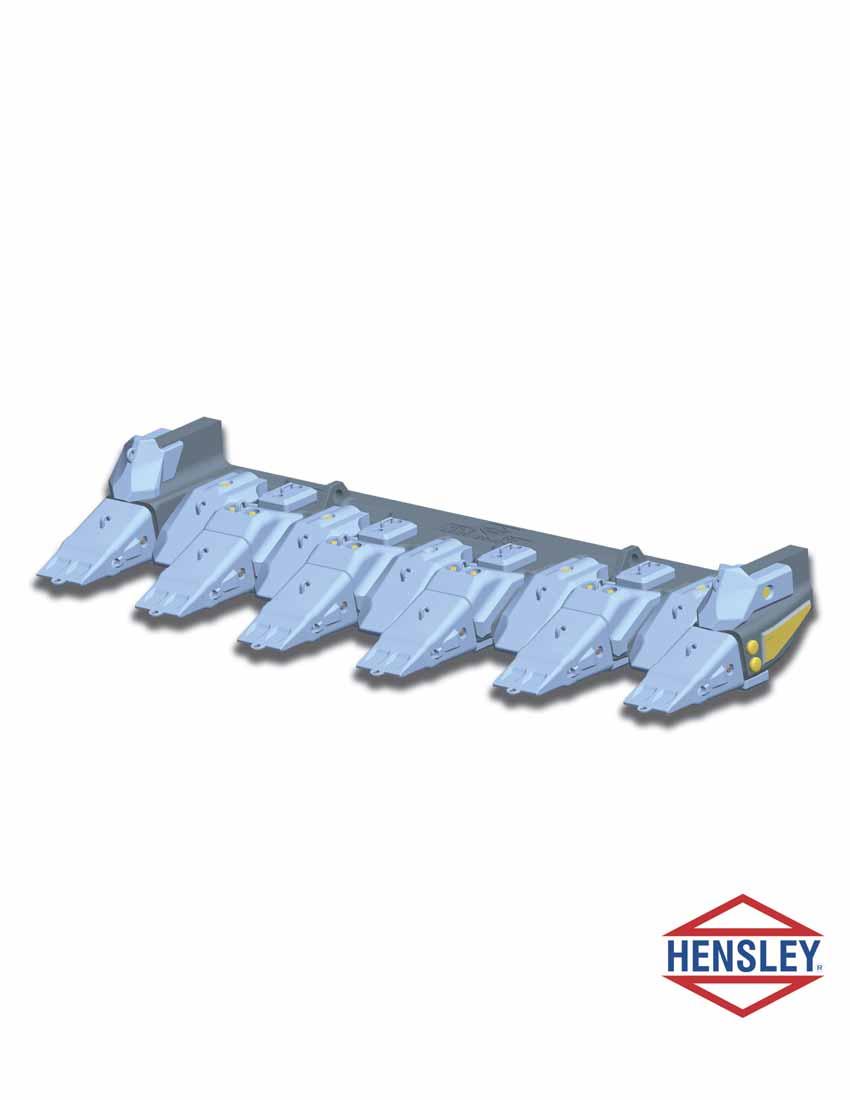
REMOVAL OF CAST LIP STEP 1 STEP 2. Layout cut lines, based on existing welds and verify with dimension taken from new lip. STEP 3
|
|
|
- Amanda Griffin
- 6 years ago
- Views:
Transcription
1
2 REMOVAL OF CAST LIP STEP 1 fig. 1-1 Brace clam from cheek plate to cheek plate (A). Brace clam from bucket floor, (just behind back of lip joint), to upper cheek plate on both sides (B). The purpose of the braces is to ensure that the geometry of the clam does not change when the old lip is removed. The size pipe/beam that is currently being used to brace the top or ears of the clam would work well for this bracing (fig fig. 1.2). fig. 1-2 STEP 2 Layout cut lines, based on existing welds and verify with dimension taken from new lip. STEP 3 Use a portable oxy/fuel cutting machine to produce as smooth a cut as possible. Some areas will need to be hand cut or gouged. Remove old lip from clam. 50
3 WELD PROCEDURE SPECIFICATION WELDING PROCEDURE SPECIFICATION (WPS) Yes Company Name HENSLEY INDUSTRIES Welding Process (es) GMAW or FCAW Supporting PQR no. (s) JOINT DESIGN USED Type: Single Double Weld Backing: Yes No Backing Material Root Opening Root Face Dimension Groove Angle Radius (J - U) Back Gouging: Yes No Method BASE METALS Material Spec. HENSLEY CAST LIP Type or Grade CARBON ALLOY CASTING Thickness: Groove Fillet Diameter (Pipe) FILLER METALS AWS Specification A5.18 or A5.2 AWS Classification ER70S-6 or E71T-1 SHIELDING Flux Gas 75% Ar 25% Co 2 Composition N/A Electrode-Flux (Class) Flow Rate CFH Gas Cup Size PREHEAT Preheat Temp., Min 300 O F (150 O C) Preheat Temp., Max 450 O F (230 O C) Interpass Temp., Min 300 O F (150 O C) Max 450 O F (230 O C) Note: If no preheat is specified and the base material is below 32 O F (0 O C), preheat to 70 O F (21 O C) and maintain throughout the welding process. Temperature should be measured using an infrared thermometer or a temperature indicating crayon stick. Identification # HI-0712 Revision 0 Date N/A By N/A Authorized by Hal Battes, CWI & CWE Date 12/31/2007 Type ----Manual Semi-Automatic Machine Automatic POSITION Position of Groove Fillet Vertical Progression: Up Down ELECTRICAL CHARACTERISTICS Transfer Mode (GMAW) Short-Ciruiting Globular Spray Current: AC DCEP DCEN Pulsed Other Tungsten Electrode (GTAW) Size: Type: TECHNIQUE Stringer or Weave Bead: STRINGER Multi-Pass or Single Pass (per side) MULTIPLE PASS Number of Electrodes Electrode Spacing Longitudinal Lateral Angle Contact Tube to Work Distance Peening PNEUMATIC NEEDLE SCALER Interpass Cleaning WIRE BRUSH POSTWELD HEAT TREATMENT Temp. Time WELDING PROCEDURE Pass or Weld Layer(s) Process Class Filler Metals Diam. Type & Polarity Current Amps or Wire Feed Speed Volts Travel Speed all GMAW ER70S-6 1/16" (1.6mm) DC ipm amps ipm all FCAW E71T-1 1/16" (1.6mm) DC ipm amps ipm 51
4 WELD PROCEDURE SPECIFICATION General Instructions: 1. Surfaces to be welded should be ground to remove cutting or gouging slag, rust, scale, paint or any other impurities that can affect the quality of the weld. 2. Cut and shape material to be used as runoff tabs, on the open ends, for the starts and stops of the weld. These tabs will be removed and ground smooth upon completion. 3. Check area to be welded for any cracks with a non-destructive test method. 4. Preheat area to be welded per specification listed in this WPS. 5. Tack weld should be a minimum of 2 (50mm) long and deposited on the back of lip joint only. 6. Welding sequence is as follows: a. Beginning in the center and working towards the sides, deposit weld on the bottom side until lip begins to pull away from the cheek plates b. Manipulate bucket to the digging position and deposit weld on the inside, back of lip joint. c. Deposit weld from the cheek plate to the cast lip corners on both sides. 7. Continue this sequence until all joints are filled. 8. Control cooling rate at the completion of the welding process with the use of thermal blankets. Cooling rate should not exceed 35 per hour. 9. Use the air carbon arc gouging process to remove the runoff tabs and grind smooth. Inspection: 1. Visual inspection shall meet the requirements of AWS14.3 Specification for Welding Earthmoving and Construction Equipment or other suitable specification. 2. Magnetic Particle inspection or Dye Penetrant inspection shall be performed 48 hours after cooling to ambient temperature. Magnetic Particle inspection is preferred. Additional notes: 1. Much care should be taken with the amount of preheat and Interpass temperatures. Too little or too much can be very detrimental to the base material. 2. Due to the condition of the bucket, actual size of bevels, and other factors unknown at this time, sequence and amount of weld in any one area, may need to be modified. 52
5 BEFORE STARTING INSTALLATION, BE SURE TO READ ALL INSTRUCTIONS THOROUGHLY! STEP 1 Bevel cheek plates and bucket bottom to create welding grooves for new cast lip. Bevel cheek plates 63.5mm (2.5 ) X 45 on the inside and the outside to allow for a full penetration weld joint. All bevels should be constructed to allow access for the welding process used. Bucket bottom should be beveled from the inside of the bucket to create a full penetration weld joint. The thicker steel areas in the center of the bucket and on both sides will need to be beveled from both the inside and the bottom side of the bucket to create a full penetration weld joint. Clean bevels and all areas to be welded. Weld surfaces must be free from cutting slag and or carbon slag from gouging. Dry, freshly ground, buffed or sanded surfaces provide the best preparation for welding. Check all bevels and surrounding area for cracks with a nondestructive testing method. STEP 2 Back of lip and lip cheek plates should be ground to remove all paint. The surfaces must be sufficiently clean so that there is nothing that may contain hydrocarbons or other impurities that can adversely affect the strength of the weld. Position and secure clam as pictured in fig Ideal position would place the cast lip on a horizontal plane, however, it is permissible to have the clam slightly rotated. This position will allow easy installation and alignment of the cast lip with the assistance of an over head crane. Welding on the back of the lip joint can be done in flat or down hand position and it is also an excellent position for achieving the proper preheat. STEP 3 fig
6 PREHEATING Preheating is the application of heat to the work piece prior to any welding, cutting, or gouging operation. All cutting and welding processes use a high temperature heat source. These high temperatures exceed the melting point of the base metal. This creates the problem of a traveling high temperature, localized heat source, and the effect that it has on the surrounding base metal. A large temperature differential causes thermal expansion and contraction, high stresses, hardened areas, and a very small area for hydrogen gasses to escape from the steel. Preheating will reduce the danger of weld cracking, reduce maximum hardness of the heat-affected zone, minimize shrinkage stresses, lessen distortion, and create a larger area for hydrogen gasses to escape from the steel. The amount of preheat is determined by the type of steels to be joined and the thickness of the steel. The cutting edge and effected areas of the bucket require a preheat temperature of 300 O F / 150 O C to 450 O F / 230 O C. It is recommended to preheat the entire cutting edge and the adjoining areas. The most common method of preheating is by torches or burners utilizing an open fuel gas flame. Open flames are difficult to control precisely. They tend to super heat one area while under heating another. A very effective way of dealing with this temperature differential is the use insulating blankets. The blankets help disperse the heat as well as retain the heat that has been input. Preheating with burners or torches is much more effective when the heat is applied from the bottom side of the work piece with insulating blankets on the topside. A ceramic element heating system, in conjunction with gas burners, is ideal. This system allows an even and through heat sink when used with insulating blankets and gas burners. Measure the preheat temperature with a temperature indicating crayon or infrared thermometer from the topside. This will insure that the preheat is not just on the surface of the material, but a complete preheat through the thickness of the materials to be welded. All material within 4 or 100mm of the weld zone must be within specified temperature. FILLER MATERIAL Recommended filler materials: American Welding Society (AWS) specification A5.18, class ER70S-6 wire for the Gas Metal Arc Welding process (GMAW) or AWS specification A5.2, class E71T-1 for the Flux Cored Arc Welding process (FCAW). Shielding gas should have a dew point of -40 O F. or lower. AWS specification A5.1, class E7018 stick electrode for the Shielded Metal Arc Welding process, (SMAW), may also be used, although it is not the preferred process. These AWS specifications may be substituted with an equivalent specification from one of the following organizations: BS British Standard issued by the British Standards Association, CSA Canadian Standard issued by the Canadian Standards Association, DIN West German Standard issued by the Deutsches Institute fuer Normung, JIS Japanese Industrial Standard issued by the Japanese Standards Association, NF French Standard issued by the Association Francaise de Normalisation. 54

7 STEP 4 Position the cutting edge (using the bucket drawing if available). Insure that the geometry of the cutting edge to the bucket is correct and cross square. After this placement has been confirmed, preheat the lip to 300 O F / 150 O C to 450 O F / 230 O C and tack weld into place. An inter-pass temperature of 300 O F / 150 O C to 450 O F / 230 O C must be maintained during this step and throughout the rest of the installation. Readings should be taken at least every half an hour to ensure that the temperature range is maintained. The first tack weld should be placed in the center of the bucket on the bottom where the cutting edge joins to the basket of the bucket. Deposit a tack weld, every 24 or 600mm, alternating from each side of center, working towards the sides of the bucket. All tack welds should be a minimum of 2 or 50mm long. DO NOT tack the check plates to the corner adapters, at this time. Begin welding the cutting edge to the basket at the bottom side center. Deposit weld equally from the centerline toward the check plates or sides of the bucket, (fig. 5-1). Stringer beads are recommended for higher strength. The use of weave or wash beads should NOT be used. Arc strikes should be avoided or ground out. Note: if the weld begins to pull the cutting edge away from the intended plane, stop and proceed to the top side STEP 5 fig. 5-1 STEP 6 Manipulate bucket to the digging position and repeat the procedure used in step 5 on the top side. Continual checks must be made to insure that the plane of the cutting edge has not changed from its desired location. The concept is to allow the lip to float prior to locking in the cheek plates. This will reduce residual stresses built up in the back of the lip joint. Continue this process of depositing weld on the bottom side and then the top side until the weld joints are filled. Alternating the weld from the bottom side to the top side will help maintain the correct plane geometry and also reduce residual stresses. Note: A tempering or annealing weld pass needs to be deposited to the weldment area that connects the bucket bottom to the cast lip. See page 58 for a description and the purpose of the tempering weld bead. 55
8 STEP 7 Cast lip corner/cheek plate joint: Establish preheat (300 O F / 150 O C to 450 O F / 230 O C) of cast lip corner and cheek plate area. Install 'groove extensions' at the front edge of the cast lip/check plate joint (fig 7-1). See page 56 for description of groove extensions. Deposit root pass joining the inside of cast lip and the inside of the cheek plate, on both sides (fig. 3-1). Back gouge the root pass from the outside of the bucket. Grind all gouged surfaces to remove all carbon slag and impurities. Re-establish preheat temperature (300 O F / 150 O C to 450 O F / 230 O C). fig. 7-1 Deposit root pass on the outside of each of the cast lip corner/cheek plate weld joints. Alternate weld passes from the outside of each cheek plate to the inside of each cheek plate for each weld layer. Alternate the direction of travel, front to back - back to front of bucket for each weld pass, utilizing the groove extensions, as shown in fig Continue process until weld joints are completely filled. Note: Final weld pass should not be adjacent to the cast lip. See page 58 for a description and the purpose of the tempering or annealing weld pass. fig
9 STEP 8 Manipulate clam on its back as pictured (fig. 8-1). Establish preheat (300 O F / 150 O Cto 450 O F / 230 O C) of cast lip corner andcheek plate area at the back of the lip. Install 'groove extensions' on the bottom edge of the cast lip/cheek plate joint (fig. 8-2). See page 56 for description of groove extensions. Deposit root pass joining the inside back of cast lip and the inside of the cheek plate on both sides. Back gouge the root pass from the OUTSIDE of the bucket. Grind all gouged surfaces to remove allcarbon slag and impurities. Re-establish preheat temperature (300 O F / 150 O C to 450 O F / 230 O C). Deposit root pass on the outside of each of the back of the cast lip corner/cheekplate weld joints. Alternate weld passes from the outside of each cheek plate to the inside of each cheek plate for each weld layer. Alternate the direction of travel, bottom to top - top to bottom of the bucket for each weld pass utilizing the groove extensions (fig. 8-2). Continue this process until weld joints are completely filled. Note: Final weld pass should not be adjacent to the cast lip. See page 58 for a description and the purpose of the annealing weld pass. fig. 8-1 fig. 8-2 WELD FINISHING / TESTING Grind blend the front edge of the cast lip/cheek plate joint. The joint should be smooth and the edges ground so that no sharp edges are present. The use of nondestructive testing of the welds and adjacent base metal, is recommended, 48 hours after the completion of all welding of the cast lip to the clam. Magnetic Particle Inspection is the preferred method. 57
10 END OF SHIFT / COMPLETION OF PROJECT When the welding project has been completed, or at the end of a working shift, the work piece should be covered with an insulating blanket to allow a slow cool down to ambient temperature. A cool down rate of no more than 25 F. or 14 C. per hour is recommended. Easily achieved with insulating blankets. TEMPERING / ANNEALING BEADS Tempering or annealing weld pass is used in all weld joints that weld is deposited against the heattreated steel castings. It is an additional weld pass that is added to the weldment once the weld joint is completely filled. This weld pass should be deposited 1/8 to 3/16 away from the final weld pass against the casting, Purpose: The heat from this weld pass tempers or anneals the final weld pass against the casting and the 'Heat Affected Zone', (HAZ), within the casting caused by the weld pass adjacent to the casting. GROOVE EXTENSIONS Groove Extensions, commonly referred to as starter tabs or run-off tabs, are used to keep the starts and stops of the weld passes out of the final weldment. Tabs should be constructed of 1/4" (6mm) thick mild steel (ASTM A36 or equivalent) and extend at least 2" (50mm) beyond the ends of the weld grooves. Tabs will be removed by the air carbon arc gouging process at the completion of the weldment. 58
11 SAFETY FIRST: Hensley recommends that you use a soft-faced hammer and ANSI-approved (Z87.1) eye protection while using our products. 88 Hensley Industries, Inc U.S./Canada all other locations Hensley Attachments U.S./Canada all other locations www. hensleyind.com Copyright 2011 Hensley Industries, Inc. This publication is protected under the copyright laws of the United States. Unauthorized duplication or distribution is prohibited. CAST LIP OWNER'S MANUAL JAN 2011
7.1. WELDING GUIDE Hensley Products
 7.1 WELDING GUIDE Preparation & Welding Process Preparation The Hensley "Welding Guide" is intended to assist customers with welding Hensley G.E.T. products. It is a general welding guide and is not all
QW-482 WELDING PROCEDURE SPECIFICATION (WPS)
") QW-482 WELDING PROCEDURE SPECIFICATION (WPS) Company Name: J.T. Thorpe & Son, Inc. By: J. Jacob Dupree, P.E., Q.C. Manager Welding Procedure Specification No.: JTT-24-CVN Revision No. 0 November 5, 2010
QW-482 WELDING PROCEDURE SPECIFICATION (WPS) Company Name: J.T. Thorpe & Son, Inc. By: J. Jacob Dupree, P.E., Q.C. Manager Welding Procedure Specification No.: JTT-24-CVN Revision No. 0 November 5, 2010
WELDING GUIDE FOR HENSLEY WELD-ON LIP SHROUDS
 WELDING GUIDE FOR HENSLEY WELD-ON LIP SHROUDS MAY 20091 TABLE OF CONTENTS Preparation of the Plate Steel and the Steel Castings...3 Welding Processes...3 Filler Material...3 Electrical Characteristics...4
1. Poor attitude toward any of the other students, instructors, or judges. 2. Failure to use personal protective equipment (PPE).
.") Welding Contest Rules and Score Sheet 2016 4G Rules: 1. Be Safe & Have Fun 2. Can tack in any position but groove welding must be in accordance with your WPS. 3. Can use wire brush, chipping hammer, and
Welding Contest Rules and Score Sheet 2016 4G Rules: 1. Be Safe & Have Fun 2. Can tack in any position but groove welding must be in accordance with your WPS. 3. Can use wire brush, chipping hammer, and
QW-482 WELDING PROCEDURE SPECIFICATION (WPS)
") QW-482 WELDING PROCEDURE SPECIFICATION (WPS) Company Name: J.T. Thorpe & Son, Inc. By: J. Jacob Dupree, Q.C. Manager Welding Procedure Specification No.: JTT-03 Date: 9/20/2016 rev. 3 Supporting PQR No.(s)
QW-482 WELDING PROCEDURE SPECIFICATION (WPS) Company Name: J.T. Thorpe & Son, Inc. By: J. Jacob Dupree, Q.C. Manager Welding Procedure Specification No.: JTT-03 Date: 9/20/2016 rev. 3 Supporting PQR No.(s)
AN OVERVIEW ON SHIELDED METAL ARC WELDING (SMAW) OF STAINLESS STEEL (SS)
 OF STAINLESS STEEL (SS)") Suggested Spec. for SMAW-SS - 1 - AN OVERVIEW ON SHIELDED METAL ARC WELDING (SMAW) OF STAINLESS STEEL (SS) Scope This document provides information on welding and related operations of stainless steel
Suggested Spec. for SMAW-SS - 1 - AN OVERVIEW ON SHIELDED METAL ARC WELDING (SMAW) OF STAINLESS STEEL (SS) Scope This document provides information on welding and related operations of stainless steel
QW-482 WELDING PROCEDURE SPECIFICATION (WPS)
") QW-482 WELDING PROCEDURE SPECIFICATION (WPS) Company Name: J.T. Thorpe & Son, Inc. By: J. Jacob Dupree, P.E., Q.C. Manager Welding Procedure Specification No.: JTT-22-STUD Revision No. 0 Date: 4/15/2009
QW-482 WELDING PROCEDURE SPECIFICATION (WPS) Company Name: J.T. Thorpe & Son, Inc. By: J. Jacob Dupree, P.E., Q.C. Manager Welding Procedure Specification No.: JTT-22-STUD Revision No. 0 Date: 4/15/2009
Core Curriculum Welding Level 1 Welding Level 2 Welding Level 3
 A Correlation of Core Curriculum Welding Level 1 Welding Level 2 Welding Level 3 to the South Carolina Standards for Welding Technology 1, 2, 3, & 4 Required Competencies South Carolina Welding Technology
WELDING PROCEDURE SPECIFICATION NO
 NATIONAL CERTIFIED PIPE WELDING BUREAU WELDING PROCEDURE SPECIFICATION NO. 1-7-1 FOR GAS METAL ARC WELDING WITH FLUXCORE WIRE (GMAW-FC) SEMI-AUTOMATIC OR MACHINE OF CARBON STEEL PIPE, VALVES, FITTINGS
ENBRIDGE PIPELINES INC. WELDING PROCEDURE DATA SHEET
 APPLICATION: Branch, Weld-O-Let, Fillet Weld New Construction & Non-Product Filled Pipelines CODE: CSA Z662-11 PROJECT: BPP (CA) MATERIAL GRADE: Run: 414 MPa (X-60) SMYS Carbon Equivalent 0.28 Maximum
PIPELINE WELDING PROCEDURE SPECIFICATION
 PIPELINE WELDING PROCEDURE SPECIFICATION Davco Welding Ltd. 1219 3 Avenue Wainwright, Alberta T9W 1K9 WPS No: Scope: DAV-16 This welding procedure specification details the procedure to be followed for
WELDING GUIDE WEAR PARTS
 WELDING GUIDE WEAR PARTS TABLE OF CONTENTS Introduction...4 Preparation Of The Plate Steel And The Steel Castings... 5 SECTION I: WELDING PROCESSES Filler Materials... 7 Electrical Characteristics...8
Introduction to Welding Technology
 Introduction to Welding Technology Welding is a fabrication process used to join materials, usually metals or thermoplastics, together. During welding, the pieces to be joined (the workpieces) are melted
welder certification welder performance qualification
 Chapter 29 Welder Certification OBJECTIVES After completing this chapter, the student should be able : Explain welder qualification and certification. Outline the steps required certify a welder. Make
Technical Data Sheet 321 Electrode Hi-Performance E-Z Arc Alloy
 321 Electrode Hi-Performance E-Z Arc Alloy A quality electrode formulated to clean contaminants and produce good base metal penetration. Once welded, it lifts the contaminants into an easy-forming slag
Approved 07/26/2017 NR Key Features. Conformances. Typical Applications. Welding Positions
 Procedures Structural Code Seismic Supplement FLUXCORED SELFSHIELDED (S) WIRE Innershield Mild Steel, All Position AWS E71T8 NR 232 Key Features High deposition rates for outofposition welding Penetrating
WELDING PROCEDURE SPECIFICATION. Shielded Metal Arc Welding-SMAW
 WELDING PROCEDURE SPECIFICATION Shielded Metal Arc Welding-SMAW WPS Number: WPS-SMAW-CS Revision: 0 Company Name & Address ABC WELDING & FABRICATING 123 WeldProc Boulevard Toronto, ON A1B 2C3 CWB Approval
WLD 152 Wire Welding Certification Practice
 WLD 152 Wire Welding Certification Practice Index Course Information Accessing ebook and coursemate info. 3 4 Science on Steel 6-10 Craftsmanship Expectations 11 Welding Projects with Information Sheets
DOWNLOAD PDF SMAW : BEADS AND FILLET WELDS
 Chapter 1 : SMAW Fillet Welds?!!! - Miller Welding Discussion Forums View Notes - SMAW -beads and fillet weldsterm: Definition: wire brush or grinder used to remove heavy mill scale or corrosion from coupons
4/19/2018. The heat generated for welding comes from an arc
 Foundations of Agriculture The heat generated for welding comes from an arc Develops when electricity jumps across an air gap between the end of an electrode and the base metal. A. Alternating Current
WELDING,FABRICATION AND REPAIRS
 WELDING,FABRICATION AND REPAIRS FABRICATION Flat profiles and formed sections can be fabricated into larger items or finished structures using conventional welding procedures. Liners may be fixed to existing
Welding. Basic Welding Welding Technician Welding Specialist. Pipe Technician. Aluminum Technician
 Welding Objectives Compass Career College s Welding program provides instruction on the various processes and techniques of welding including oxyfuel cutting, carbon arc cutting, shielded metal arc welding,
APPLIED SKILLS AND KNOWLEDGE
 WELDING APPLIED SKILLS AND KNOWLEDGE PERFORM TECHNICAL READING 1 Identify details and specifications 2 Follow detailed directions 3 Use book mechanics (tables, index, etc.) 4 Locate information and problem
WELDING TECHNOLOGY AND WELDING INSPECTION
 WELDING TECHNOLOGY AND WELDING INSPECTION PRESENTED BY: GOPAL KUMAR CHOUDHARY SVL ENGINEERING SERVICES CHENNAI CONTENTS: DEFINATION TYPES OF WELDING ELECTRODE GEOMETRY EQUIPMENT QUALITY PROCESS SAFETY
Manitoba Welder Practical Examination STRUCTURAL LEVEL 2
 STRUCTURAL LEVEL 2 The Manitoba Welder Practical Examination is designed to test the scope of practical knowledge and skills of the trade. Please read all the information throughout this package. All candidates
49 CFR Part 192. Not applicable to welding during manufacture of pipe and components
 49 CFR Part 192 Not applicable to welding during manufacture of pipe and components --- and other strange nomenclature A joining process that produces a coalescence of metals (or non-metals) by heating
CIMC: Introduction to Agricultural Power and Technology
 CIMC: Introduction to Agricultural Power and Technology Unit 3- Shielded Metal Arc Welding 1. Shielded Metal Arc Welding also goes by other names. Which of the following is another term for this type of
TEACH YOUR TRADE. WE LL DO THE REST.
 TEACH YOUR TRADE. WE LL DO THE REST. ENROLLMENT IN SKILLED TRADE PROGRAMS IS UP 70%. IS YOUR WORKFORCE DEVELOPMENT CURRICULUM READY? Credit: Texas State Technical College Welding Program The Wall Street
ALLOYS COMPANY Stephenson Hwy, Madison Heights, MI (248) (800)
 (800)") Stainless Steel Alloys Gas Metal Arc Welding Gas Tungsten Arc Welding Shielded Metal Arc Welding (GMAW) MIG Wires (GTAW) TIG Alloys (SMAW) Stick Electrode The Royal Line ALLOYS COMPANY 30105 Stephenson
Stainless Steel Alloys Gas Metal Arc Welding Gas Tungsten Arc Welding Shielded Metal Arc Welding (GMAW) MIG Wires (GTAW) TIG Alloys (SMAW) Stick Electrode The Royal Line ALLOYS COMPANY 30105 Stephenson
Industrial Technology: Welding Technology Crosswalk to AZ Language Arts Standards
 East Page 1 of 1 August 1998 1.0 Perform safety, maintenance and housekeeping procedures. 1.3 Use directions on handling of hazardous materials. 1.6 Interpret material safety data sheets. 1.12 Conduct
FABRICATION/WELDING STANDARD MANUAL
 This manual was produced for internal use at Geringhoff Manufacturing LLC. We strongly recommend our suppliers to read and adhere to it. It is of great help to understand our drawings and our expectations.
!!!! WARNING!!!! WELDING FUMES AND GASES CAN BE DANGEROUS TO YOUR HEALTH.
 CAREFULLY!!!! WARNING!!!! CAREFULLY WELDING FUMES AND GASES CAN BE DANGEROUS TO YOUR HEALTH. BEFORE USING THIS PRODUCT THE WELDER (END-USER) MUST READ AND UNDERSTAND THE COMPLETE PRODUCT WARNING LABEL
G009: Remove weld metal from plain carbon steel, using weld washing techniques.
 Welding 1 st Quarter DUTY A: Practicing Occupational Orientation A001: Follow safe practices. A002: Prepare time or job cards, reports, or records. A003: Perform housekeeping duties. A004: Follow oral
Flux Cored Wire (FCW)
") Flux Cored Wire (FCW) Gas Shielded Type Flux Cored Wire (FCAW) Welding Consumables Selection Product name Specification Characteristic description GMX70 E70T-1C CO 2, DC+, high de rate titania type, only
Flux Cored Wire (FCW) Gas Shielded Type Flux Cored Wire (FCAW) Welding Consumables Selection Product name Specification Characteristic description GMX70 E70T-1C CO 2, DC+, high de rate titania type, only
QC Inspection and Qualification Procedure- TX-EDU-VT-1-07, Revision # by Richard J DePue, Supersedes IW-VT-1 Visual Inspection Procedure
 1.0 Scope: QC Inspection and Qualification Procedure- TX-EDU-VT-1-07, Revision #6 03-04-2016 by Richard J DePue, Supersedes IW-VT-1 Visual Inspection Procedure The purpose of this procedure is to define
Welding. What is Welding?
 Welding Welding What is Welding? Welding is a joining process in which metals are heated, melted and mixed to produce a joint with properties similar to those of the materials being joined. Parent Metal
Canadian Welding Bureau Welding Procedure Qualification AWS D1.1 vs CSA W47.1
 Welding Procedure Qualification Canadian Welding Bureau Welding Procedure Qualification Comparison of Key Concepts and Requirements This document provides a general comparison of key concepts and requirements
INSPECTION OF FIELD WELDING
 INSPECTION OF FIELD WELDING Objective Types of Projects Involving Welding Common Welding Terms & Symbols Welder Qualifications Common Welding Requirements Welding Inspection Types of Projects Involving
Planning Advisory Notice
 Planning Advisory Notice Welding Inspection Tasks The Role of the Inspector In the first PAN welding series, we discussed standards, specifications, codes, and responsibilities of those involved in the
Training Achievement Record
 Training Achievement Record AWS SENSE LEVEL I ENTRY WELDER TRAINING ACHIEVEMENT RECORD Name Trainee ID # Date Entered Training Training Facility Address Address Address Telephone # INSTRUCTOR USE ONLY
WELDING PROCEDURE SPECIFICATION NO
 NATIONAL CERTIFIED PIPE WELDING BUREAU WELDING PROCEDURE SPECIFICATION NO. 45-32-1 FOR GAS TUNGSTEN ARC WELDING (GTAW) AND SHIELDED METAL ARC WELDING (SMAW) OF NICKEL ALLOY 20 (UNS N08020) PIPE, VALVES,
SMAW. Shielded metal arc welding (SMAW) is commonly referred to as stick welding
 is commonly referred to as stick welding") SMAW EQUIPMENT SMAW Shielded metal arc welding (SMAW) is commonly referred to as stick welding An electric arc between the stick electrode and the base metal creates heat. Heat melts the base metal and
SMAW EQUIPMENT SMAW Shielded metal arc welding (SMAW) is commonly referred to as stick welding An electric arc between the stick electrode and the base metal creates heat. Heat melts the base metal and
TECH TIPS. Booms/Scissors. Service Call: Platform repair instructions of steel guard rails on Terex/Genie Aerial Work Platforms and Scissors
 TECH TIPS Service Call: Platform repair instructions of steel guard rails on Terex/Genie Aerial Work Platforms and Scissors Tools Needed: See attached document for required tools Model: Booms/Scissors
PILE WELDING QUALITY CONTROL PLAN
 Michigan Department Of Transportation 5627 (10/14) PILE WELDING QUALITY CONTROL PLAN CONTRACTOR LOCATION PREPARED BY CONTROL SECTION JOB NO. DATE Bridge Field Services Approval Block CHECKED BY DATE SPECIFICATIONS
OIL TECH SERVICES, INC.
 OIL TECH SERVICES, INC. 800 Wilcrest, Suite 100 Houston, TX 77042-1359 (310)-527-2695 (713) 789-5144 E Mail: mlombard@itmreps.com Website: www.itmreps.com WELDING Weld Procedure Specifications (WPS): Welding
Pipeline Systems PLSC0017 Requirements for Welder Qualifications in Accordance with ASME Section IX
 June 2018 Pipeline Systems PLSC0017 Requirements for Welder Qualifications in Accordance with ASME Section IX PURPOSE AND USE OF PROCESS INDUSTRY PRACTICES In an effort to minimize the cost of process
Lecture 23. Chapter 30 Fusion Welding Processes. Introduction. Two pieces are joined together by the application of heat
 Lecture 23 Chapter 30 Fusion Welding Processes Introduction Fusion welding Two pieces are joined together by the application of heat Melting and fusing the interface Filler metal Extra metal added (melted)
API-582. a practical approach for industrial welding practices. All rights reserved to thepetrostreet team
 Recommended Welding Guidelines API-582 a practical approach for industrial welding practices By The PetroStreet Team CONTENTS Key Sections: Θ Section 6 WELDING CONSUMABLES Θ Section 7 SHIELDING AND PURGING
Extended stickout guides are used to maintain a consistent CTWD (see Contact Tip to Work Distance section for more details).
.") WELDING TECHNIQUES Extended Stickout Welding (Cont d) Extended stickout welding is best suited to large diameter, high deposition Innershield electrodes, such as 3/32 in. (2.4 mm) and 0.120 in. (3.0 mm)
WELDING TECHNIQUES Extended Stickout Welding (Cont d) Extended stickout welding is best suited to large diameter, high deposition Innershield electrodes, such as 3/32 in. (2.4 mm) and 0.120 in. (3.0 mm)
pdfmachine trial version
 EFFECT OF WELDING TECHNIQUES (GTAW & SMAW) ON THE MICROSTRUCTURE & MECHANICAL PROPERTIES OF MILD STEEL SA 516 Gr. 70 By Dr. Muhammad Taqi Zahid Butt, S. Ahmed, S. Rasool, U. Ali and S. U. Rehman* ABSTRACT
ALLOYS COMPANY Stephenson Hwy, Madison Heights, MI (248) (800)
 (800)") Stainless Steel Alloys Gas Metal Arc Welding Gas Tungsten Arc Welding Shielded Metal Arc Welding (GMAW) Wires (GTAW) Alloys (SMAW) Stick The Royal Line ALLOYS COMPANY 30105 Stephenson Hwy, Madison Heights,
Stainless Steel Alloys Gas Metal Arc Welding Gas Tungsten Arc Welding Shielded Metal Arc Welding (GMAW) Wires (GTAW) Alloys (SMAW) Stick The Royal Line ALLOYS COMPANY 30105 Stephenson Hwy, Madison Heights,
MANUAL METAL ARC (MMA) STICK WELDING
 STICK WELDING") AN INTRODUCTION TO MANUAL METAL ARC (MMA) STICK WELDING Proline Welding Supplies sales@prolinewelding.com 0800 699 353 WARNING: This document contains general information about the topic discussed herein.
AN INTRODUCTION TO MANUAL METAL ARC (MMA) STICK WELDING Proline Welding Supplies sales@prolinewelding.com 0800 699 353 WARNING: This document contains general information about the topic discussed herein.
3 2 1 N 1. Safety AWS (EG2.0-95) *1. Identify and correct or report safety hazards [A01] 9. Identify structural shapes, sizes, and weights [A18]
![3 2 1 N 1. Safety AWS (EG2.0-95) *1. Identify and correct or report safety hazards [A01] 9. Identify structural shapes, sizes, and weights [A18]](/thumbs/90/101368572.jpg "3 2 1 N 1. Safety AWS (EG2.0-95) *1. Identify and correct or report safety hazards [A01] 9. Identify structural shapes, sizes, and weights [A18]") Name: Welding Directions: Evaluate the student by checking the appropriate number or letter to indicate the degree of competency. The rating for each task should reflect employability readiness rather
Name: Welding Directions: Evaluate the student by checking the appropriate number or letter to indicate the degree of competency. The rating for each task should reflect employability readiness rather
Materials & Processes in Manufacturing
 2003 Bill Young Materials & Processes in Manufacturing ME 151 Chapter 37 Arc Processes Chapter 38 Resistance Welding Chapter 39 Brazing and Soldering 1 Introduction Arc welding processes produce fusion
CONSTRUCTION SPECIFICATION FOR STRUCTURAL STEEL
 ONTARIO PROVINCIAL STANDARD SPECIFICATION METRIC OPSS 906 FEBRUARY 1993 CONSTRUCTION SPECIFICATION FOR STRUCTURAL STEEL 906.01 SCOPE 906.02 REFERENCES 906.03 DEFINITIONS TABLE OF CONTENTS 906.04 SUBMISSION
Productivity Enhancements for GMAW of Titanium Carrie Davis and Michael E. Wells Naval Surface Warfare Center, Carderock Division
 Productivity Enhancements for GMAW of Titanium Carrie Davis and Michael E. Wells Naval Surface Warfare Center, Carderock Division While titanium has been used extensively in seawater cooling systems on
21433 SW Oregon Street Sherwood, Oregon USA Tel Fax WELD INSPECTION & REPAIR REQUIRED ON THE MAIN BOOM.
 Marine Crane E. A Division of Allied Systems Company SERVICE BULLETIN 4 SW Oregon Street Sherwood, Oregon 9740-9799 USA Tel 50.65.560 Fax 50.65.7980 DATE: August, 07 PAGE: of 4 REVISED: BULLETIN NO.: CSB005
GAS METAL ARC WELDING (GMAW)
") GAS METAL ARC WELDING (GMAW) INTRODUCTION Gas Metal Arc Welding (GMAW) is also called Metal Inert Gas (MIG) arc welding. It uses consumable metallic electrode. There are other gas shielded arc welding
GAS METAL ARC WELDING (GMAW) INTRODUCTION Gas Metal Arc Welding (GMAW) is also called Metal Inert Gas (MIG) arc welding. It uses consumable metallic electrode. There are other gas shielded arc welding
KCWONG. Shielded Metal Arc Welding (SMAW) Gas Metal Arc Welding (GMAW/MIG) Flux-cored Arc Welding (FCAW) Gas Tungsten Arc Welding (GTAW/TIG) KCWONG
 Gas Metal Arc Welding (GMAW/MIG) Flux-cored Arc Welding (FCAW) Gas Tungsten Arc Welding (GTAW/TIG) KCWONG") 1 Shielded Metal Arc Welding (SMAW) Gas Metal Arc Welding (GMAW/MIG) Flux-cored Arc Welding (FCAW) Gas Tungsten Arc Welding (GTAW/TIG) 2 Working Principle Equipment Filler metals Advantages Limitation
1 Shielded Metal Arc Welding (SMAW) Gas Metal Arc Welding (GMAW/MIG) Flux-cored Arc Welding (FCAW) Gas Tungsten Arc Welding (GTAW/TIG) 2 Working Principle Equipment Filler metals Advantages Limitation
WELD PROCEDURE DATA. Carrier Pipe Thickness (WT): 6.4 mm < WT = 31.8 mm (Design and CSA Z662 Cl )
: 6.4 mm < WT = 31.8 mm (Design and CSA Z662 Cl )") WELD PROCEDURE DATA WPS: WEI-30-1 Rev. 0 Application: Branch and Lap (Sleeve) Connections on non-flowing, gas lines which are either pressured or non-pressured. Supporting PQR: WEI-30-1-1 (Branch) Qualification
WELD PROCEDURE DATA WPS: WEI-30-1 Rev. 0 Application: Branch and Lap (Sleeve) Connections on non-flowing, gas lines which are either pressured or non-pressured. Supporting PQR: WEI-30-1-1 (Branch) Qualification
Combat old foes with new technology in LNG tank construction
 Combat old foes with new technology in LNG tank construction Semi-automatic FCAW with alternating current reduces arc blow issues P. van Erk, D. Fleming The Lincoln Electric company 17-3-2012 Principle
Structural Welding Code Reinforcing Steel
 Key Words Allowable stress, inspection, qualification, reinforcing steel, structural details, welded joint details AWS D1.4/D1.4M:2005 An American National Standard Approved by the American National Standards
GMAW Unit Topics. During this overview, we will discuss the following topics:
 GMAW (MIG Welding) GMAW Unit Topics During this overview, we will discuss the following topics: Safety GMAW Basics Equipment Set-Up Welding Variables Process Advantages and Limitations AWS Connection National
MAG wire. Welding Consumables Selection. MAG MIG wire/rod. Welding Consumables Selection. Specifi cation AWS JIS. Product name
 Welding Consumables Selection Product name S-4 S-6 Shielding gas Property description Better deoxidation effect than ER70S-3, no charpy impact requirement. Available for single and multipasses, good anti-rust
!!!! WARNING!!!! WELDING FUMES AND GASES CAN BE DANGEROUS TO YOUR HEALTH.
 !!!! WARNING!!!! WELDING FUMES AND GASES CAN BE DANGEROUS TO YOUR HEALTH. BEFORE USING THIS PRODUCT THE WELDER (END-USER) MUST READ AND UNDERSTAND THE COMPLETE PRODUCT WARNING LABEL AND MATERIAL SAFETY
American Welding Society Nashville Section. Welding Procedure Development
 American Welding Society Nashville Section Welding Procedure Development AWS & ASME Welding Procedures Welding Procedure Specification (WPS) Written document that provides direction to the welder for making
WITHLACOOCHEE TECHNICAL INSTITUTE Welding Technology J Course Syllabus
 WITHLACOOCHEE TECHNICAL INSTITUTE Welding Technology J400400 Course Syllabus Course Description Instruction includes learning experiences in the joining and cutting of metal materials with the different
!!!! WARNING!!!! WELDING FUMES AND GASES CAN BE DANGEROUS TO YOUR HEALTH.
 !!!! WARNING!!!! WELDING FUMES AND GASES CAN BE DANGEROUS TO YOUR HEALTH. BEFORE USING THIS PRODUCT THE WELDER (END-USER) MUST READ AND UNDERSTAND THE COMPLETE PRODUCT WARNING LABEL AND MATERIAL SAFETY
WLD 225 Gas Tungsten Arc Welding (Mild Steel) Pipe II
 Pipe II") WLD 225 Gas Tungsten Arc Welding (Mild Steel) Pipe II Index Math on Metal 9-14 Science on Steel 15-20 Watt s Pipe Cutting Information Sheets 21-24 Watt s Pipe Grinding Information Sheets 25-27 Pipe Fitting
WLD 225 Gas Tungsten Arc Welding (Mild Steel) Pipe II Index Math on Metal 9-14 Science on Steel 15-20 Watt s Pipe Cutting Information Sheets 21-24 Watt s Pipe Grinding Information Sheets 25-27 Pipe Fitting
Section 13. Welding Field Welding 1. Welding Processes 6. Stud Welding 9. Welding Positions 15
 Section 13 Welding 13.1 Field Welding 1 Welding Processes 6 Stud Welding 9 Welding Positions 15 Field Welding Section 13 Field Welding Bridge Structures AWS D1.5 (00560.26(a)) Reinforcement AWS D1.4 (00530.42(d))
Welder Level 2 Rev. December, 2016
 Welder Level 2 Welder Unit: D2 Quality Assurance Level: Two Duration: 14 hours Theory: Practical: 14 hours 0 hours Overview: This unit is designed to introduce knowledge of quality control measures used
Submerged Arc Welding: A discussion of the welding process and how welding parameters affect the chemistry ofcorrosion Resistant Overlays (CRO)
") Submerged Arc Welding: A discussion of the welding process and how welding parameters affect the chemistry ofcorrosion Resistant Overlays (CRO) 1 Submerged Arc Welding (SAW) Part 1 The SAW welding process
Submerged Arc Welding: A discussion of the welding process and how welding parameters affect the chemistry ofcorrosion Resistant Overlays (CRO) 1 Submerged Arc Welding (SAW) Part 1 The SAW welding process
Item 448 Structural Field Welding
 Item 448 Structural Field Welding 1. DESCRIPTION 2. MATERIALS Field-weld metal members using the shielded metal arc or flux cored arc welding processes. Provide electrodes for shielded metal arc welding
Welding (WELD) WELD 1330 Basic GTAW (TIG) Welding
 WELD 1330 Basic GTAW (TIG) Welding") 1 Welding (WELD) WELD 1030 Arc Welding Fundamentals This course provides an overview of the basic knowledge and skills related to welding. It does not provide hands-on welding experience. Topics include
1 Welding (WELD) WELD 1030 Arc Welding Fundamentals This course provides an overview of the basic knowledge and skills related to welding. It does not provide hands-on welding experience. Topics include
MUELLER GAS. Line Stopper Fittings for. Reliable Connections. Preparation Procedures 2. Installation / Welding 3-5. Side-Out Fitting Installation 6
 operating Instructions manual MUELLER GAS TAble of contents PAGE Line Stopper Fittings for Preparation Procedures 2 Installation / Welding 3-5 Side-Out Fitting Installation 6 Notes 7 Steel Gas Mains! WARNING:.
WELDING (442) Welding (442) Flux Cored Arc Welding (FCAW)
 Welding (442) Flux Cored Arc Welding (FCAW)") WELDING (442) 442-308 Flux Cored Arc Welding (FCAW) Welding (442) 1 Information provided includes course descriptions by subject only. For complete 2018-2019 programs/academic plans, please refer to Academic
WELDING (442) 442-308 Flux Cored Arc Welding (FCAW) Welding (442) 1 Information provided includes course descriptions by subject only. For complete 2018-2019 programs/academic plans, please refer to Academic
Shielded Metal Arc Pipe Welding
 Shielded Metal Arc Pipe Welding State of Oklahoma Welding Duty/Task Crosswalk The following state of Oklahoma welding tasks, which are aligned to AWS standards, are covered in MAVCC S welding series. Shielded
WORLDSKILLS STANDARD SPECIFICATION
 WORLDSKILLS STANDARD SPECIFICATION Skill 10 Welding WSC2017_WSSS10 THE WORLDSKILLS STANDARDS SPECIFICATION (WSSS) GENERAL NOTES ON THE WSSS The WSSS specifies the knowledge, understanding and specific
NAME 345 Welding Technology Lecture 03 (Welding Joint Design)
") NAME 345 Welding Technology Lecture 03 (Welding Joint Design) Md. Habibur Rahman Lecturer Department of Naval Architecture & Marine Engineering Bangladesh University of Engineering & Technology Dhaka-1000,
NAME 345 Welding Technology Lecture 03 (Welding Joint Design) Md. Habibur Rahman Lecturer Department of Naval Architecture & Marine Engineering Bangladesh University of Engineering & Technology Dhaka-1000,
ITEM 448 STRUCTURAL FIELD WELDING
 ITEM 448 STRUCTURAL FIELD WELDING 448.1. Description. This Item shall govern for the field welding of structural steel, reinforcing steel, and miscellaneous steel items as shown on the plans and in accordance
Job Ready Assessment Blueprint. Welding. Test Code: 4172 / Version: 01. Copyright 2013 NOCTI. All Rights Reserved.
 Job Ready Assessment Blueprint Welding Test Code: 4172 / Version: 01 Copyright 2013 NOCTI. All Rights Reserved. General Assessment Information Blueprint Contents General Assessment Information Written
NATURAL GAS COMPRESSOR STATION PIPELINE WELDING AND RELATED FACILITIES. Engr. Md. Saidur Rahman 1,*
 Proceedings of the International Conference on Mechanical Engineering and Renewable Energy 2015 (ICMERE2015) 26 29 November, 2015, Chittagong, Bangladesh ICMERE2015-PI-243 NATURAL GAS COMPRESSOR STATION
DIVISION: METALS SECTION: STRUCTURAL STEEL FRAMING REPORT HOLDER: CAST CONNEX CORPORATION
 0 Most Widely Accepted and Trusted ICC ES Evaluation Report ICC ES 000 (800) 423 6587 (562) 699 0543 www.icc es.org ESR 3031 Reissued 12/2017 This report is subject to renewal 12/2019. DIVISION: 05 00
Table of Contents Page No.
 Table of Contents Personnel... iii Foreword...v List of Tables... xiii List of Figures...xiv List of Forms...xvi 1. General Provisions...1 1.1 Application...1 1.2 Base Metal...1 1.3 Welding Processes...2
Welding Units and Understanding Statements
 Course #: IT72 Grade Level: 9-12 Course Name: Welding II Level of Difficulty: Average Prerequisites: None # of Credits: 2 semesters 1 credit The following is a Career and Technical Education (CTE) class
Weld Procedure WP-004-NC. SMAW Carbon Steel Alloys
 Weld Procedure WP-004-NC Rev. (3) SMAW Carbon Steel Alloys Approved By: Susan Q. Jones Susan Q. Jones Quality Assurance Supervisor Released By: JamesSmith James Smith QEHS Manager ACCEPTABLE FOR USE: on
Chapter 12. Flux Cored Arc Welding Equipment, Setup, and Operation Delmar, Cengage Learning
 Chapter 12 Flux Cored Arc Welding Equipment, Setup, and Operation Objectives Explain the FCA welding process Describe what equipment is needed for FCA welding List the advantages of FCA welding, and explain
A Practical Design Guide for Welded Connections Part 1 Basic Concepts and Weld Symbols
 A Practical Design Guide for Welded Connections Part 1 Basic Concepts and Weld Symbols by James Doane, PhD, PE Course Overview This course is divided into 2 parts. Though it provides some basic concepts
LUNA COMMUNITY COLLEGE
 LUNA COMMUNITY COLLEGE Welding Program Curriculum Profile 2012-2015 COMPETENCIES 1 Program Goal: The program prepares students with entry-level job skills in all phases of the welding industry and provides
INSPECTION AND TEST. PROCEDURE Total Page 13
 PROCEDURE Total Page 13 Client : Project Name: P/O No. : Item No. : 3 2 1 0 FOR APPROVAL Rev Description Date Prepared By Checked By Approved By PROCEDURE Page 1 of 8 1. General 1.1 Scope This specification
Ontario ENGINEERING STANDARD GUIDELINE 1.0 PURPOSE 2.0 THERMITE WELDING 2.1 WELD PROCEDURE
 /7.0 PURPOSE The following guideline addresses the minimum requirements to successfully thermite weld. This is not meant to supersede the thermite kit manufacturer s procedure / methodology. 2.0 THERMITE
ME E5 - Welding Metallurgy
 ME 328.3 E5 - Welding Metallurgy Purpose: To become more familiar with the welding process and its effects on the material To look at the changes in microstructure and the hardness in the Heat Affected
Welding of Large Diameter Pipelines: Design, Processes, Procedures Specifications for Welding Steel Water Pipe
 Welding of Large Diameter Pipelines: Design, Processes, Procedures Specifications for Welding Steel Water Pipe Field Welding of Steel Pipe Joints Nash Williams, Owner National Welding Corporation 2 Steel
VIII. Techniques for Basic Weld Joints
 VIII. Techniques for Basic Weld Joints Arc Length, Gas Cup Size, and Electrode Extension As a rule of thumb, the arc length is normally one electrode diameter as seen in Figure 8.1. This would hold true
Tack Welder Level 3 Question Bank
 Tack Welder Level 3 Question Bank I Fill in the blanks 1. Principle of GAS cutting is 2. Argon cylinder colour is 3. rays will emit from welding arc. 4. Tongs are used to hold 5. Full form of GMAW 6. Diameter
AASHTO/AWS D1.5M/D1.5:2008. Table of Contents
 Table of Contents Personnel...v Foreword...ix List of Tables... xviii List of Figures...xix List of Forms...xxi 1. General Provisions...1 1.1 Application...1 1.2 Base Metal...1 1.3 Welding Processes...1
Variants of MIG/MAG Flux Cored Arc Welding (FCAW)
") Variants of MIG/MAG Flux Cored Arc Welding (FCAW) Professor Pedro Vilaça * * Contacts Address: P.O. Box 14200, FI-00076 Aalto, Finland Visiting address: Puumiehenkuja 3, Espoo pedro.vilaca@aalto.fi ; Skype:
Variants of MIG/MAG Flux Cored Arc Welding (FCAW) Professor Pedro Vilaça * * Contacts Address: P.O. Box 14200, FI-00076 Aalto, Finland Visiting address: Puumiehenkuja 3, Espoo pedro.vilaca@aalto.fi ; Skype:
Section 14. Welding Field Welding 1. Welding Processes 6. Stud Welding 9. Welding Positions 11
 Section 14 Welding 14.1 Field Welding 1 Welding Processes 6 Stud Welding 9 Welding Positions 11 Field Welding Section 14.1 Field Welding Bridge Structures AWS D1.5 (00560.26(a)) Reinforcement AWS D1.4