THERMAL CYCLING RELIABILITY OF CHIP RESISTOR LEAD FREE SOLDER JOINTS
|
|
|
- Lambert James
- 6 years ago
- Views:
Transcription
1 THERMAL CYCLING RELIAILITY OF CHIP RESISTOR LEAD FREE SOLDER JOINTS Jeffrey C. Suhling, H. S. Gale, R. Wayne Johnson, M. Nokibul Islam, Tushar Shete, Pradeep Lall, Michael J. ozack, John L. Evans Center for Advanced Vehicle Electronics (CAVE) Auburn University Auburn, AL Phone: (334) Fax: (334) Ping Seto, Tarun Gupta, James R. Thompson DaimlerChrysler - Huntsville Electronics 100 Electronics oulevard Huntsville, AL ASTRACT The solder joint reliability of ceramic chip resistors assembled to laminate substrates has been a long time concern for systems exposed to harsh environments such as those found in automotive and aerospace applications. This is due to a combination of the extreme temperature excursions experienced by the assemblies along with the large coefficient of thermal expansion mismatches between the alumina bodies of the chip resistors and the glass-epoxy composites of the printed circuit boards (PCs). These reliability challenges are exacerbated for components with larger physical size (distance to neutral point) such as the 2512 resistors used in situations where higher voltages and/or currents lead to power dissipations up to 1 Watt. In this work, the thermal cycling reliability of several 2512 chip resistor lead free solder joint configurations has been investigated. In an initial study, a comparison has been made between the solder joint reliabilities obtained with components fabricated with both tin-lead and pure tin solder terminations. In the main portion of the reliability testing, two temperature ranges (-40 to 125 o C and -40 to 150 o C) and five different solder alloys have been examined. The investigated solders include the normal eutectic SnAgCu (SAC) alloy recommended by earlier studies (95.5Sn-3.8Ag-0.7Cu), and three variations of the lead free ternary SAC alloy that include small quaternary additions of bismuth and indium to enhance fatigue resistance. For each configuration, thermal cycling failure data has been gathered and analysed using two-parameter Weibull models to rank the relative material performances. The obtained lead free results have been compared to data for standard 63Sn-37Pb joints. In addition, a second set of thermally cycled samples was used for microscopy studies to examine crack propagation, changes in the microstructure of the solders, and intermetallic growth at the solder to PC pad interfaces. INTRODUCTION Legislation that mandates the banning of lead in electronics, due to environmental and health concerns, has been actively pursued in several countries during the past 15 years. Although the products covered by and implementation deadlines for such legislation continue to evolve, it is clear that laws requiring conversion to lead-free electronics are becoming a reality. Other factors that are affecting the push towards the elimination of lead in electronics are the market differentiation and advantage being realized by companies producing so-called green products that are lead-free. A large number of research studies have been performed and are currently underway in the lead-free solder area. Detailed reports on multi-year studies have been published by the National Center for Manufacturing Sciences (NCMS) and the National Electronics Manufacturing Initiative (NEMI), as well as other consortia. Although no drop in replacement has been identified for all applications; Sn-Ag, Sn-Ag-Cu (SAC), and other alloys involving elements such as Sn, Ag, Cu, i, In, and Zn have been identified as promising replacements for standard 63Sn-37Pb eutectic solder. There have been many reports that solder joint reliability can actually be increased for a given application by using a lead-free replacement alloy such as Sn-Ag-Cu instead of conventional Sn-Pb. However, this conclusion is not universal, and the degree of reliability improvement or degradation is package/design and environment dependent. In thermal cycling reliability environments, Sn-Ag-Cu alloys appear to often outperform Sn-Pb. This has been found for solder joints in more compliant package-board assemblies such as leaded components (e.g. QFPs) and Plastic all Grid Array (PGA) applications [1], and also for more stiff components (CGA) subjected to small temperature changes [2]. However, for very stiff components with a high coefficient of thermal expansion (CTE) mismatch with the substrate (e.g. CGA on FR-4, and non-underfilled flip chip on laminate), the solder joint reliability is typically poorer for lead-free Sn- Ag-Cu alloys in thermal cycling tests with large swings between the temperature extremes [3-4]. Another common Surface Mount Technology (SMT) configuration involving stiff components with high CTE mismatch to the substrate is the use of ceramic (alumina) bodied chip resistors on organic substrates (e.g. glass-epoxy laminates). The solder joint reliability of such components has been a long time concern for harsh environments with extreme temperature excursions, such as those found in automotive and aerospace applications. These reliability challenges are further exacerbated for components with larger physical


2 size (distance to neutral point) such as the 2512 resistors used in situations where higher voltages and/or currents lead to power dissipations up to 1 Watt. Crack growth and the resulting shear strength degradation for both Sn-Ag-Cu and Sn-Pb-Ag chip resistor solder joints have been examined during thermal cycling [5]. It was found that the fatigue resistances between lead bearing and SAC solder joints were not significantly different, but were influenced by the component type and board metallization. In addition, crack length variation has been measured in chip capacitor solder joints as a function of thermal cycling [6]. Cracks were found to grow fastest in the Sn-Pb-Ag solder joints relative to several lead free alternatives. Finally, the changes in microstructure occurring in Sn-Ag-Cu chip resistor solder joints during thermal cycling have been recently examined [7]. A power law relationship was established between the number of cycles to crack initiation and the average β -Sn phase growth parameter. In this work, the thermal cycling reliability of several 2512 chip resistor lead free solder joint configurations has been investigated. In an initial study, a comparison was made between the solder joint reliabilities obtained with components fabricated with both tin-lead and pure tin solder terminations. In the main portion of the reliability testing, two temperature ranges (-40 to 125 o C and -40 to 150 o C) and five different solder alloys have been examined. The investigated solders include the normal eutectic SnAgCu (SAC) alloy recommended by earlier studies (95.5Sn-3.8Ag-0.7Cu), and three variations of the lead free ternary SAC alloy that include small quaternary additions of bismuth and indium to enhance fatigue resistance. For each configuration, thermal cycling failure data has been gathered and analysed using two-parameter Weibull models to rank the relative material performances. The obtained lead free results have been compared to data for standard 63Sn-37Pb joints. In addition, a second set of thermally cycled samples was used for microscopy studies to examine crack propagation, changes in the microstructure of the solders, and intermetallic growth at the solder to PC pad interfaces. TEST OARD A test board was developed for examining the thermal cycling reliability of five sizes of chip resistors (2512, 1206, 0805, 0603, 0402). The industry standard naming convention for these chip resistor sizes describes the length and width of the resistor body in hundredths of an inch. For example, the 2512 resistor has a nominal length of.25 inches (6.35mm), and a nominal width of.12 inches (3.05mm). Each board contained 15 of each of the 5 sizes of chip resistors. The 15 resistors in each size were accessible electrically as 3 daisy-chain sets (5 resistors and thus 10 solder joints per chain). The resistor daisy chains were routed to plated through holes at the edge of the board where soldered wire connections could be made for use in resistance monitoring during the thermal cycling tests. Figure 1 is a photograph of an assembled test board. The fabricated test boards included four copper conductor layers, FR-406 glass/epoxy laminate material and had a thickness of 1.57 mm. The external copper traces had either a Hot Air Solder Leveled (HASL) Sn-Pb or an Electroless Nickel Immersion Gold (ENIG) finish. Figure 2 shows a top view of one of the 2512 resistors and a typical uncycled solder joint cross-section. 200 µm 1 mm Figure 1 - Chip Resistor Test oard Figure Resistor Top View and Solder Joint RELIAILITY TESTING Thermal cycling (-40 to 125 o C and -40 to 150 o C) of the assembled test boards was performed in a pair of lue-m environmental chambers, and 6000 cycles were completed for each temperature range before the testing was terminated. The thermal cycle duration was 90 minutes, with 30 minutes at each extreme. Typical thermocouple results from under a component on one of the test boards are illustrated in Figure 3. Enough boards were assembled so that each of the various legs of the test matrix had 12 test boards (36 resistor chains for each component size). The boards were placed vertically in the chamber, and the wiring passed through access ports to a data acquisition system. Monitoring of the various daisy chain networks was performed throughout the cycling using a high accuracy digital multimeter coupled with a high performance switching system controlled by LabView software. Failure of a daisy-chain network was defined as the point when the resistance change exceeded 5Ω. RELIAILITY DATA In this paper, only results for the 2512 resistor solder joint reliability will be discussed. Of all the tested chip components, the 2512 resistors have the largest body size and highest rated power dissipation, and consequently the poorest solder joint reliability. For those components with sufficient failures after 6000 cycles, the resulting failure data were statistically analysed using two parameter Weibull models. The standard parameters in such an approach are the Weibull Slope β, and the Characteristic Life η, which is the number of
3 cycles required to cause failure of 63.2% of the samples from a particular leg of the test matrix. From these values for a particular chip resistor configuration, the cumulative failures (percent) after any number of thermal cycles can be predicted. 160 Temperature ( o C) Time (min) Figure 3 - Test oard Thermal Cycle (-40 to 125 o C) Figure 4 - Weibull Plot for Resistor Termination Study Resistor Termination Study Prior to studying the reliability differences between the various solder types, an initial investigation was performed to examine the effects of using different termination materials for the chip resistors. Historically, chip resistors have been fabricated with 90Sn-10Pb solder terminations to better match the Sn-Pb solder paste used in conventional SMT assembly and to avoid fillet lifting. However, a transition to pure Sn terminations has occurred as a part of the overall lead free initiative. In the resistor termination study performed here, 2512 resistors from two vendors, with both Sn-Pb and Sn terminations were considered. The boards were fabricated with a Sn-Pb HASL finish, and eutectic 63Sn-37Pb solder paste was utilized. Thus, the only lead-free attributes of these particular experiments were the Snterminations in some of the chip resistors. The Weibull failure plot for the Sn and Sn-Pb terminated chip components is shown in Figure 4. From these data, it can be seen that there was little difference in the failure data for the two termination types for a given resistor vendor, although the parts from vendor 2 consistently outperformed those from vendor 1. The nature of these reliability differences for the parts from the two vendors has yet to be explained. In all future discussions in this paper, resistors from vendor 2 with pure Sn termination were utilized. Lead Free Alloy Study The compositions of the five alloys (four lead free and standard 63Sn-37Pb) tested in this investigation are tabulated in Table 1. The lead free solders consisted of the standard SAC eutectic (95.5Sn-3.8Ag-0.7Cu) that is often recommended as a leading candidate for replacement of Sn-Pb, and a set of three quaternary Sn-Ag-Cu-X alloys, with either i or In as the fourth ingredient. The test boards utilized in this part of the investigation were fabricated with an Electroless Nickel Immersion Gold (ENIG) finish. Table 1 - Solder Alloy Compositions Alloy Sn-Pb Sn-Ag-Cu Sn-Ag-Cu-i (1) Sn-Ag-Cu-i (2) Sn-Ag-Cu-In Composition 63Sn-37Pb 95.5Sn-3.8Ag-0.7Cu 92.35Sn-3.35Ag-1.0Cu-3.3i 93.5Sn-3.8Ag-0.7Cu-2.0i 88.5Sn-3.0Ag-0.5Cu-8.0In Typical thermal cycling reliability data for the 2512 resistor solder joints are shown below in Figures 5-7. In Figures 5 and 6, the reliabilities of 63Sn-37Pb and 95.5Sn-3.8Ag-0.7Cu solder joints are compared for the -40 to 125 o C and -40 to 150 o C temperature ranges, respectively. It can be seen from Figure 5, that the reliabilities are very similar for the -40 to 125 o C thermal cycling range. However, Figure 6 indicates that 63Sn-37Pb dramatically outperforms the lead free Sn-Ag-Cu alloy for the more extreme -40 to 150 o C testing. This result agrees with the earlier observations for non-underfilled flip chip on laminate assemblies [3-4], and further underscores the need to be cautious when proposing lead-free solder substitutions for SMT configurations including stiff components on organic laminate substrates where there are harsh environments with large temperature swings (e.g. automotive under-the-hood applications). In the case of cycling from -40 to 125 o C, the reliabilities of the three quaternary Sn-Ag-Cu-X alloys were found to be the same or slightly lower than that of eutectic 95.5Sn-3.8Ag-0.7Cu. However, as shown in Figure 7, the addition of either i or In to Sn-Ag-Cu can significantly enhance the reliability of the lead free joints when exposed to the harsher -40 to 150 o C temperature range, where Sn-Ag-Cu performs poorer than standard Sn-Pb. Further investigation is required in order to determine the Sn-Ag-Cu-X lead free alloy formulation that best optimizes reliability in harsh environments.
 Figure 8 - Photograph of an Uncycled 95.5Sn-3.8Ag-0.")


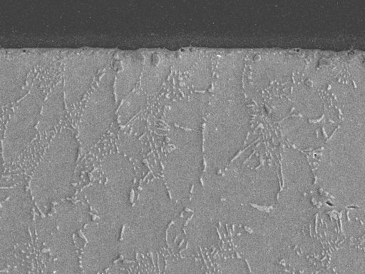
4 Figure 5 - Weibull Plot for 2512 Chip Resistors with Sn-Pb Figure 6 - Weibull Plot for 2512 Chip Resistors with Sn-Pb and Sn-Ag-Cu Solders (-40 to 125 o C) and Sn-Ag-Cu Solders (-40 to 150 o C) 200 µm Figure 7 - Weibull Plot for 2512 Chip Resistors with Lead Free Solders (-40 to 150 o C) Figure 8 - Photograph of an Uncycled 95.5Sn-3.8Ag-0.7Cu Solder Joint with Images and Locations of Crack Initiation, Corner Turning, and Completion Selected from Various Cycled Samples MICROSCOPY AND FAILURE ANALYSIS Experimental Techniques Metallographic samples were prepared from cross-sections of a set of supplemental boards subjected to various levels of thermal cycling. The cross-sections were characterized by scanning electron microscopy (SEM) using a JEOL JSM 840 instrument operated at an accelerating voltage of 20 kv. All samples were imaged as polished. The intermetallic phases observed in these joints were noticeably harder than the matrix. Thus, it was possible to obtain topographic contrast in secondary electron images (SEIs) of the polished samples without resort to etching. ackscattered electron images (EIs) were also used to produce atomic number contrast (phases with a high average atomic number appear bright). Compositional data was obtained using energy dispersive x-ray spectroscopy (EDS) via an Oxford ultrathin window (UTW) detector and ISIS analyzer attached to the JSM 840. Crack Propagation Preliminary failure analysis has shown that the solder joint cracking and creep-fatigue damage propagates as expected for chip resistors on FR-4 substrates. As shown in Figures 8-9, cracks begin underneath the component and then typically follow along a path that parallels the resistor termination, turning the corner at the resistor edge, and then proceeding until complete separation has occurred. Unfortunately, insufficient cross-sections were made to fully characterize the crack growth for the various solders. In particular, the Weibull plots in Figures 5-7 indicate that many more cross-sections with environmental exposures between 500 and 3000 cycles would be necessary to develop a crack propagation criterion for the 2512 resistor solder joints. Another finding was that more study is needed to optimize the assembly process and reflow profile for each lead free solder type so that voids (see Figure 10) are minimized in the solder joints.
 Figure 10 - Chip Resistor Lead Free Solder Joint with Void Solder Fillet Microstructures Example secondary electron images for the")


 for microstructural characterization, which was not practicable given the large number")
5 200 µm 200 µm 500 Cycles 1000 Cycles 2000 Cycles 3000 Cycles 4000 Cycles 5000 Cycles Figure 9 - Observed Cracks in 95.5Sn-3.8Ag-0.7Cu Joints After Various Numbers of Thermal Cycles (-40 to 150 o C) Figure 10 - Chip Resistor Lead Free Solder Joint with Void Solder Fillet Microstructures Example secondary electron images for the lead free solder joints that were cross-sectioned after various levels of thermal cycling from -40 to 150 o C are shown in Figures In all cases, the magnified images were taken at the interface of the solder and PC pad with ENIG plating finish, in the bulk of the joint but near the corner of the resistor termination. For all four of the lead free systems, a noticeable feature was that spheroidizing of the eutectic was observed to progress rapidly during cycling. Such spheroidization is driven by the energy of the interfaces between the phases making up the eutectic, since spheroidization reduces the total interfacial area and hence total interfacial energy. Spheroidization depends on diffusion transport, and would therefore have occurred during the hot part of the thermal cycles. y changing the distribution of hard, brittle intermetallics, spheroidization can often have a significant effect on the mechanical properties of eutectic microstructures. For example, spheroidization can break up networks of brittle phases that would otherwise act as a continuous path for crack propagation. Spheroidization, does not involve a phase transformation, but simply a morphological change. However, this does not preclude the possibility of phase transformations occurring simultaneously with spheroidization. In the present study, it was difficult to determine if such transformations had occurred, due to the small size of some of the particles involved, which were below the spatial resolution of EDS (typically ~ 1 mm). Also, the apparent compositions of the larger particles, whose composition could be determined using EDS, did not tie up with the limited available phase diagrams. Identification of subtle microstructural changes would require the use of transmission electron microscopy (TEM) for microstructural characterization, which was not practicable given the large number of samples involved. Spheroidization commenced quickly and was clearly apparent in all samples after only 500 cycles. There were variations in the extent of spheroidization within each alloy and an unequivocal difference in spheroidization from alloy to alloy was not apparent. ased on the results discussed above, differences in the gross fillet microstructure alone would not seem to account for the marked differences in thermal fatigue performance of the alloys studied. Intermetallic Layers The formation of distinct intermetallic layers was observed at the interfaces with the solders as seen in Figures Use of x-ray elemental mapping techniques has shown that the copper and nickel layers largely remained on the surface of the PC, because the intermetallic layer acted to some extent as a diffusion barrier. Nonetheless, sufficient copper and nickel diffused into the solder to form a variety of fine (a few mm in diameter) second phases throughout the fillets in all of the systems studied, as illustrated in the backscattered electron images in Figure 13. A distinct difference between the alloys studied was the nature of the intermetallic layers (see Figures 11-12) during cycling from -40 to 150 o C. The intermetallic layers in the 95.5Sn-3.8Ag-0.7Cu alloy and the two Sn-Ag-Cu-i alloys were fairly fine (typically around 1-3 mm thick) and continuous. In contrast, the Sn-Ag-Cu-In alloy produced a highly irregular intermetallic layer consisting of large (10-20 mm) angular precipitates (see Figure 12). An unequivocal compositional difference could not be confirmed between the intermetallic layers formed in these different alloys. This analysis was complicated by EDS spot-size issues (see above) and overlaps between the In and Sn x-ray peaks. Since the 88.5Sn-3.0Ag-0.5Cu-8.0In alloy performed best in the -40 to 150 o C thermal cycling testing, and the 95.5Sn- 3.8Ag-0.7Cu the worst, the size and morphology of these intermetallics could be the reason for the observed differences in performance between these alloys. However, a clear correlation was not observed between the performance of the various alloys investigated and any single microstructural feature. SUMMARY AND CONCLUSIONS In this work, the thermal cycling reliability of several 2512 chip resistor lead free solder joint configurations has been investigated, with the motivation of qualifying lead free solders for harsh environment applications in ground and aerospace vehicles. In an initial study, a comparison was made between the solder joint reliabilities obtained with components fabricated with both tin-lead and pure tin solder terminations. For parts from two vendors, little difference was seen in the reliabilities for the two termination types. However, there was a noticeable difference in the reliabilities found for components from the two vendors.


6 0 cycles 20 µm 0 cycles 500 cycles 500 cycles 1000 cycles 1000 cycles 5000 cycles 5000 cycles Figure 11 - SEM Images of 95.5Sn-3.8Ag-0.7Cu Joints vs. Thermal Cycling (-40 to 150 oc) 20 µm Figure 12 - SEM Images of 88.5Sn-3.0Ag-0.5Cu-8.0In Joints vs. Thermal Cycling (-40 to 150 oc)

 and five different solder alloys. The two parameter Weibull failure plots indicated that the eutectic SAC alloy (95.5Sn-3.8Ag-0.")
7 A A A 20 µ m E 500 Cycles C D A D Identifier A C D E F Elemental Constituents Ag, In Au, In Sn Sn, Ni, Cu Sn, Ni Ag, Sn C E F E 4000 Cycles F Figure 13 - Phases and Elemental Constituents for 88.5Sn-3.0Ag-0.5Cu-8.0In Joints after 500 and 4000 Cycles In the main portion of the experimentation, reliability testing of 2512 solder joints was performed using two temperature ranges (-40 to 125 o C and -40 to 150 o C) and five different solder alloys. The two parameter Weibull failure plots indicated that the eutectic SAC alloy (95.5Sn-3.8Ag-0.7Cu) recommended by earlier studies has similar reliability to standard 63Sn-37Pb for testing from -40 to 125 o C. However, 63Sn-37Pb joints dramatically outperformed the lead free Sn-Ag-Cu alloy joints for the more extreme -40 to 150 o C testing. This result agrees with earlier observations for CGA and non-underfilled flip chip on laminate assemblies (configurations with high stiffness components, large CTE mismatches, and large temperature excursions). Such results further underscore the need to be cautious when proposing lead-free solder substitutions for SMT configurations in harsh environments. The measured data also indicated that quaternary variations of the lead free SAC alloy (Sn-Ag-Cu-X), which include small percentages of bismuth and indium, can be used to enhance the -40 to 150 o C thermal cycling fatigue resistance relative to standard 95.5Sn-3.8Ag-0.7Cu. A second set of thermally cycled samples was used for microscopy studies to examine crack propagation, changes in the microstructure of the solders, and intermetallic growth at the solder to PC pad interfaces. Failure analysis has shown that the solder joint cracking and creep-fatigue damage propagates as expected for chip resistors on FR-4 substrates. Cracks begin underneath the component and then typically follow along a path that parallels the resistor termination until complete separation has occurred. Voiding was also observed in several of the lead free solder joints, illustrating the need to further optimize the assembly process and reflow profile for each lead free solder type. This voiding is one possible explanation for the variations from linearity (waviness) and low beta values in the Weibull failure data. Another contributing factor could be material property variations. Further work is needed to fully understand the fundamental reasons for the relative reliability rankings of the solders and the Weibull slope variations. Spheroidizing of the eutectic was observed to progress rapidly during cycling of all of the lead free alloys, and was clearly apparent in all samples after only 500 cycles. There were variations in the extent of spheroidization within each alloy and unequivocal differences in spheroidization from alloy to alloy were not apparent. It is believed that differences in the gross fillet microstructure alone do not account for the marked differences in the thermal fatigue performance of the alloys studied. A distinct difference between the alloys studied was the nature of the intermetallic layers. The intermetallic layers in the two Sn-Ag-Cu-i alloys and the 95.5Sn-3.8Ag-0.7Cu alloy were fairly fine (typically around 1-3 mm thick) and continuous. In contrast, the Sn-Ag-Cu-In alloy produced a highly irregular intermetallic layer consisting of large (10-20 mm) angular precipitates. Since this indium variation of the standard SAC metallurgy performed best in the -40 to 150 o C thermal cycling testing, the size and morphology of these intermetallics could be the reason for the observed differences in reliability performances of these alloys at high temperatures. However, a clear correlation was not observed between the performance of the various alloys investigated and any single microstructural feature. ACKNOWLEDGMENTS The work was supported by the NSF Center for Advanced Vehicle Electronics (CAVE).
8 REFERENCES 1. Lau, J. H., Hoo, N., Horsley, R., Smetana, J., Shangguan, D., Dauksher, W., Love, D., Menis, I. and Sullivan,. Reliability testing and data analysis of high-density packages lead-free solder joints, Proceedings of APEX 2003, Paper S42-3, pp. 1-24, Anaheim, CA, Farooq, M., Goldmann, L., Martin, G., Goldsmith, C. and ergeron, C., Thermo-mechanical fatigue reliability of Pb-free ceramic ball grid arrays: experimental data and lifetime prediction modeling, Proceedings of the 53rd IEEE Electronic Components and Technology Conference, pp , New Orleans, LA, May 28-30, Schubert, A., Dudek, R., Walter, H., Jung, E., Gollhardt, A., Michel,., Reichl, H., Reliability Assessment of Flip-Chip Assemblies with Lead-Free Solder Joints, Proceedings of the 52 nd Electronic Components and Technology Conference, San Diego, CA, May 28-31, Schubert, A., Dudek, R., Auerswald, E., Gollhardt, A., Michel,., Reichl, H., Fatigue Life Models for SnAgCu and SnPb Solder Joints Evaluated by Experiments and Simulation, Proceedings of the 53 rd Electronic Components and Technology Conference, pp , New Orleans, LA, May 28-30, Stam, F. A., and Davitt, E., Effects of Thermomechanical Cycling on Lead and Lead-Free (SnPb and SnAgCu) Surface Mount Solder Joints, Microelectronics Reliability, Vol. 41, pp , Grossmann, G., Nicoletti, G., and Soler, U., Results of Comparative Reliability Tests on Lead-Free Solder Alloys, Proceedings of the 52 nd Electronic Components and Technology Conference, San Diego, CA, May 28-31, Sayama, T., Takayanagi, T., Nagai, Y., Mori, T., and Yu, Q., Evaluation of Microstructural Evolution and Thermal Fatigue Crack Initiation in Sn-Ag-Cu Solder Joints, Proceedings of InterPACK 03, Paper Number IPACK , pp.1-8, Lahaina, HI, July 6-11, 2003.
THERMAL CYCLING RELIABILITY OF LEAD FREE SOLDERS
 THERMAL CYCLING RELIABILITY OF LEAD FREE SOLDERS FOR AUTOMOTIVE APPLICATIONS Jefsey C. Suhlmg, H. S. Gale, R. Wayne Johnson, M. Nokibul Islam, Tushar Shete, Pradeep Lall, Michael J. Bozack, John L. Evans
RELIABILITY OF DOPED LEAD-FREE SOLDER JOINTS UNDER ISOTHERMAL AGING AND THERMAL CYCLING
 As originally published in the SMTA Proceedings RELIABILITY OF DOPED LEAD-FREE SOLDER JOINTS UNDER ISOTHERMAL AGING AND THERMAL CYCLING Cong Zhao, Thomas Sanders, Chaobo Shen, Zhou Hai, John L. Evans,
ENHANCING MECHANICAL SHOCK PERFORMANCE USING EDGEBOND TECHNOLOGY
 ENHANCING MECHANICAL SHOCK PERFORMANCE USING EDGEBOND TECHNOLOGY Steven Perng, Tae-Kyu Lee, and Cherif Guirguis Cisco Systems, Inc. San Jose, CA, USA sperng@cisco.com Edward S. Ibe Zymet, Inc. East Hanover,
Composition/wt% Bal SA2 (SABI) Bal SA3 (SABI + Cu) Bal
 Bal SA3 (SABI + Cu) Bal") Improving Thermal Cycle and Mechanical Drop Impact Resistance of a Lead-free Tin-Silver-Bismuth-Indium Solder Alloy with Minor Doping of Copper Additive Takehiro Wada 1, Seiji Tsuchiya 1, Shantanu Joshi
Improving Thermal Cycle and Mechanical Drop Impact Resistance of a Lead-free Tin-Silver-Bismuth-Indium Solder Alloy with Minor Doping of Copper Additive Takehiro Wada 1, Seiji Tsuchiya 1, Shantanu Joshi
EFFECT OF Ag COMPOSITION, DWELL TIME AND COOLING RATE ON THE RELIABILITY OF Sn-Ag-Cu SOLDER JOINTS. Mulugeta Abtew
 EFFECT OF Ag COMPOSITION, DWELL TIME AND COOLING RATE ON THE RELIABILITY OF Sn-Ag-Cu SOLDER JOINTS Mulugeta Abtew Typical PCB Assembly Process PCB Loading Solder Paste Application Solder Paste Inspection
SOLDER JOINT RELIABILITY TEST SUMMARY
 Project Number: SJR Tracking Code: TC0623-SEAF-SJR-1059 Requested by: Jeremy Wooldridge Date: 05/20/2008 Product Rev: D (SEAF), C (SEAM) Part #: SEAF-50-5.0-S-10-2-A/ SEAM-50-2.0-S-10-2-A SEAF-50-6.5-S-10-1-A/
Lead-Free Solder Bump Technologies for Flip-Chip Packaging Applications
 Lead-Free Solder Bump Technologies for Flip-Chip Packaging Applications Zaheed S. Karim 1 and Jim Martin 2 1 Advanced Interconnect Technology Ltd. 1901 Sunley Centre, 9 Wing Yin Street, Tsuen Wan, Hong
Reliability of Lead-Free Solder Connections for Area-Array Packages
 Presented at IPC SMEMA Council APEX SM 2001 For additional information, please email marketing@amkor.com Reliability of Lead-Free Solder Connections for Area-Array Packages Ahmer Syed Amkor Technology,
System Level Effects on Solder Joint Reliability
 System Level Effects on Solder Joint Reliability Maxim Serebreni 2004 2010 Outline Thermo-mechanical Fatigue of solder interconnects Shear and tensile effects on Solder Fatigue Effect of Glass Style on
MARCH National Physical Laboratory Hampton Road Teddington Middlesex United Kingdom TW11 0LW
 NPL REPORT DEPC-MPR 044 Measuring the Impact of Land Size and Solder Joint Volume on Lead-free Solder Joint Reliability M Wickham, L Zou, M Dusek and C P Hunt NOT RESTRICTED MARCH 2006 National Physical
The Morphology Evolution and Voiding of Solder Joints on QFN Central Pads with a Ni/Au Finish
 The Morphology Evolution and Voiding of Solder Joints on QFN Central Pads with a Ni/Au Finish Julie Silk 1, Jianbiao Pan 2, Mike Powers 1 1 Agilent Technologies, 1400 Fountaingrove Parkway, Santa Rosa,
Effect of local grain distribution and Enhancement on edgebond applied wafer-level chip-scale package (WLCSP) thermal cycling performance
 thermal cycling performance") Effect of local grain distribution and Enhancement on edgebond applied wafer-level chip-scale package (WLCSP) thermal cycling performance 1 Tae-Kyu Lee, 2 Weidong Xie, 2 Steven Perng, 3 Edward Ibe, and
Effect of local grain distribution and Enhancement on edgebond applied wafer-level chip-scale package (WLCSP) thermal cycling performance 1 Tae-Kyu Lee, 2 Weidong Xie, 2 Steven Perng, 3 Edward Ibe, and
Composition/wt% Bal SA2 (SABI) Bal SA3 (SABI + Cu) Bal
 Bal SA3 (SABI + Cu) Bal") Improving Thermal Cycle and Mechanical Drop Impact Resistance of a Lead-free Tin-Silver-Bismuth-Indium Solder Alloy with Minor Doping of Copper Additive Takehiro Wada 1, Seiji Tsuchiya 1, Shantanu Joshi
Improving Thermal Cycle and Mechanical Drop Impact Resistance of a Lead-free Tin-Silver-Bismuth-Indium Solder Alloy with Minor Doping of Copper Additive Takehiro Wada 1, Seiji Tsuchiya 1, Shantanu Joshi
Reliability Testing of Ni-Modified SnCu and SAC305 - Vibration. Keith Sweatman, Nihon Superior Joelle Arnold, DfR Solutions March 2008
 Reliability Testing of Ni-Modified SnCu and SAC305 - Vibration Keith Sweatman, Nihon Superior Joelle Arnold, DfR Solutions March 2008 2004-2008 Previous Work Accelerated Life Testing of SN100C for Surface
Low-Silver BGA Assembly Phase II Reliability Assessment Fifth Report: Preliminary Thermal Cycling Results
 Low-Silver BGA Assembly Phase II Reliability Assessment Fifth Report: Preliminary Thermal Cycling Results Gregory Henshall 1 Michael Fehrenbach 2 Hewlett-Packard Co. 1 Palo Alto, CA USA 2 Houston, TX USA
room and cold readouts were performed every 250 cycles. Failure data and Weibull plots were generated. Typically, the test vehicles were subjected to
 SOLDER JOINT RELIABILITY ASSESMENT OF Sn-Ag-Cu BGA COMPONENTS ATTACHED WITH EUTECTIC Pb-Sn SOLDER Fay Hua 1, Raiyo Aspandiar 2, Cameron Anderson 3, Greg Clemons 3, Chee-key Chung 4, Mustapha Faizul 4 Intel
ENHANCING WLCSP RELIABILITY THROUGH BUILD-UP STRUCTURE IMPROVEMENTS AND NEW SOLDER ALLOYS
 ENHANCING WLCSP RELIABILITY THROUGH BUILD-UP STRUCTURE IMPROVEMENTS AND NEW SOLDER ALLOYS B. Rogers, M. Melgo, M. Almonte, S. Jayaraman, C. Scanlan, and T. Olson Deca Technologies, Inc 7855 S. River Parkway,
Thermal cyclic test for Sn-4Ag-0.5Cu solders on high P Ni/Au and Ni/Pd/Au surface finishes
 Journal of Mechanical Engineering and Sciences (JMES) ISSN (Print): 2289-4659; e-issn: 2231-8380; Volume 9, pp. 1572-1579, December 2015 Universiti Malaysia Pahang, Malaysia DOI: http://dx.doi.org/10.15282/jmes.9.2015.4.0152
TEMPERATURE CYCLING AND FATIGUE IN ELECTRONICS
 TEMPERATURE CYCLING AND FATIGUE IN ELECTRONICS Gilad Sharon, Ph.D. DfR Solutions Beltsville, MD, USA gsharon@dfrsolutions.com Greg Caswell DfR Solutions Liberty Hill, TX, USA gcaswell@dfrsolutions.com
Welcome to SMTA Brazil Chapter Brook Sandy-Smith Dr. Ron Lasky Tim Jensen
 Welcome to SMTA Brazil Chapter 2013 Presented by Authors Ivan Castellanos Edward Briggs Brook Sandy-Smith Dr. Ron Lasky Tim Jensen Advantages / Concerns HP testing Mechanical properties New work Area ratio
Investigation of the Lead-free Solder Joint Shear Performance
 Investigation of the Lead-free Solder Joint Shear Performance James Webster Jianbiao Pan, Ph.D. Brian J. Toleno, Ph.D. Cal Poly State University Cal Poly State University Henkel Technologies Industrial
EFFECT OF THERMAL AGING ON THE IMC LAYER BETWEEN SnAgSb SOLDER AND Cu SUBSTRATE. Universiti Kebangsaan Malaysia, 43600, Bangi, Selangor, Malaysia
 EFFECT OF THERMAL AGING ON THE IMC LAYER BETWEEN SnAgSb SOLDER AND Cu SUBSTRATE W. Shualdi 1, I. Ahmad 1, G. Omar 2 and A. Isnin 3 1 Department of Electrical, Electronic and System, Faculty of Engineering,
Effect of Process Variations on Solder Joint Reliability for Nickel-based Surface Finishes
 Effect of Process Variations on Solder Joint Reliability for Nickel-based Surface Finishes Hugh Roberts Atotech USA Inc., Rock Hill, SC, USA Sven Lamprecht, Gustavo Ramos and Christian Sebald Atotech Deutschland
Lead Free Solder for Flip Chip
 Lead Free Solder for Flip Chip Zhenwei Hou & R. Wayne Johnson Laboratory for Electronics Assembly & Packaging Auburn University 162 Broun Hall, ECE Dept. Auburn, AL 36489 USA 334-844-1880 johnson@eng.auburn.edu
Pressure-Assisted Low-Temperature Sintering of Silver Paste as an Alternative Die-Attach Solution to Solder Reflow
 Pressure-Assisted Low-Temperature Sintering of Silver Paste as an Alternative Die-Attach Solution to Solder Reflow Zhiye (Zach) Zhang and Guo-Quan Lu Center for Power Electronics Systems The Bradley Department
A study aimed at characterizing the interfacial structure in a tin silver solder on nickel-coated copper plate during aging
 Sādhanā Vol. 33, Part 3, June 2008, pp. 251 259. Printed in India A study aimed at characterizing the interfacial structure in a tin silver solder on nickel-coated copper plate during aging D C LIN 1,
Thermo-Mechanical FEM Analysis of Lead Free and Lead Containing Solder for Flip Chip Applications
 Thermo-Mechanical FEM Analysis of Lead Free and Lead Containing Solder for Flip Chip Applications M. Gonzalez 1, B. Vandevelde 1, Jan Vanfleteren 2 and D. Manessis 3 1 IMEC, Kapeldreef 75, 3001, Leuven,
Growth Kinetics of Reaction Layers in Flip Chip Joints with Cu-cored Lead-free Solder Balls
 Materials Transactions, Vol. 5, No. 3 () pp. 75 to 75 Special Issue on Lead-Free Soldering in Electronics # The Japan Institute of Metals Growth Kinetics of Reaction Layers in Flip Chip Joints with Cu-cored
COMPONENT LEVEL RELIABILITY FOR HIGH TEMPERATURE POWER COMPUTING WITH SAC305 AND ALTERNATIVE HIGH RELIABILITY SOLDERS
 As originally published in the SMTA Proceedings. COMPONENT LEVEL RELIABILITY FOR HIGH TEMPERATURE POWER COMPUTING WITH SAC305 AND ALTERNATIVE HIGH RELIABILITY SOLDERS Thomas Sanders, Sivasubramanian Thirugnanasambandam
Solder Alloy Evolution and Development
 Solder Alloy Evolution and Development SMTA Boston November 4, 2018 Presented by Timothy O Neill, Technical Marketing Manager, AIM A Brief Review of Electronic Solders 1960 s to 2006 Tin/Lead (Sn/Pb) Solder
HOW THE MOLD COMPOUND THERMAL EXPANSION OVERRULES THE SOLDER COMPOSITION CHOICE IN BOARD LEVEL RELIABILITY PERFORMANCE
 HOW THE MOLD COMPOUND THERMAL EXPANSION OVERRULES THE SOLDER COMPOSITION CHOICE IN BOARD LEVEL RELIABILITY PERFORMANCE AUTHORS: B. VANDEVELDE, L. DEGRENDELE, M. CAUWE, B. ALLAERT, R. LAUWAERT, G. WILLEMS
Thermal Fatigue Evaluation of Pb-Free Solder Joints: Results, Lessons Learned, and Future Trends
 JOM, Vol. 67, No. 10, 2015 DOI: 10.1007/s11837-015-1595-1 2015 The Minerals, Metals & Materials Society Thermal Fatigue Evaluation of Pb-Free Solder Joints: Results, Lessons Learned, and Future Trends
Optimizing Immersion Silver Chemistries For Copper
 Optimizing Immersion Silver Chemistries For Copper Ms Dagmara Charyk, Mr. Tom Tyson, Mr. Eric Stafstrom, Dr. Ron Morrissey, Technic Inc Cranston RI Abstract: Immersion silver chemistry has been promoted
Growth of Intermetallic Compounds during Isothermal Annealing of a Sn-Ag-Cu Lead-free Solder
 Accepted for publication in Soldering & Surface Mount Technology, Emerald, United Kingdom, 2004, in press. Growth of Intermetallic Compounds during Isothermal Annealing of a Sn-Ag-Cu Lead-free Solder S.L.
Development of a Lead-Free Alloy for High-Reliability, High-Temperature Applications
 Development of a Lead-Free Alloy for High-Reliability, High-Temperature Applications Hector Steen, Ph.D. 1 and Brian Toleno, Ph.D. 2 Henkel Corporation 1 Irvine, CA, USA 2 Hemel Hempstead, UK brian.toleno@us.henkel.com
BOARD LEVEL RELIABILITY COMPARISON OF LEAD FREE ALLOYS
 BOARD LEVEL RELIABILITY COMPARISON OF LEAD FREE ALLOYS Robert Darveaux, Corey Reichman, Sabira Enayet, Wen-Sung Hsu, and Win Thandar Swe Amkor Technology, Inc. Chandler, AZ, USA rdarv@amkor.com ABSTRACT
MICROSTRUCTURE AND RELIABILITY OF LOW AG, BI-CONTAINING SOLDER ALLOYS
 MICROSTRUCTURE AND RELIABILITY OF LOW AG, BI-CONTAINING SOLDER ALLOYS Eva Kosiba, Simin Bagheri, Polina Snugovsky, Ph.D. Celestica Inc. Toronto, ON, Canada ekosiba@celestica.com, sbagheri@celestica.com,
2006 DMSMS Conference Pb-free Solder Technical Issues (Not Including Tin Whiskers)
") 2006 DMSMS Conference Pb-free Solder Technical Issues (Not Including Tin Whiskers) Dr. Stephan Meschter BAE Systems LEAP WG Technical Guidelines Handbook Leader Johnson City, NY Phone: 607-770-2332, Email:
2006 DMSMS Conference Pb-free Solder Technical Issues (Not Including Tin Whiskers) Dr. Stephan Meschter BAE Systems LEAP WG Technical Guidelines Handbook Leader Johnson City, NY Phone: 607-770-2332, Email:
Future Electronic Devices Technology in Cosmic Space and Lead-free Solder Joint Reliability
 The 22nd Microelectronics Work Future Electronic Devices Technology in Cosmic Space and Lead-free Solder Joint Reliability Key Points (1) High Speed Solder Ball Shear Test (2) Relationship between Surface
Lead-Free Connectors - An Overview
 Lead-Free Connectors - An Overview Pete Elmgren Molex Inc. 15 August 2003 Introduction For more than 50 years, lead-bearing solders have been used almost exclusively throughout the electronics industry
RELIABILITY IMPACT OF COPPER-DOPED EUTECTIC TIN-LEAD BUMP AND ITS VOIDING UPON FLIP CHIP ASSEMBLIES
 RELIABILITY IMPACT OF COPPER-DOPED EUTECTIC TIN-LEAD BUMP AND ITS VOIDING UPON FLIP CHIP ASSEMBLIES David Ihms and Shing Yeh Delphi Electronics & Safety Kokomo, IN, USA david.w.ihms@delphi.com and shing.yeh@delphi.com
Unique Failure Modes from use of Sn-Pb and Lead-Free (mixed metallurgies) in PCB Assembly: CASE STUDY
 in PCB Assembly: CASE STUDY") Unique Failure Modes from use of Sn-Pb and Lead-Free (mixed metallurgies) in PCB Assembly: CASE STUDY Frank Toth, and Gary F. Shade; Intel Corporation, Hillsboro, OR, USA {francis.toth.jr@intel.com, (503)-696-1546}
Unique Failure Modes from use of Sn-Pb and Lead-Free (mixed metallurgies) in PCB Assembly: CASE STUDY Frank Toth, and Gary F. Shade; Intel Corporation, Hillsboro, OR, USA {francis.toth.jr@intel.com, (503)-696-1546}
Compatibility of Lead-free Solders with PCB Materials
 Compatibility of Lead-free Solders with PCB Materials Miloš Dušek, Jaspal Nottay and Christopher Hunt August 2001 2 August 2001 Compatibility of Lead-free Solders with PCB Materials Miloš Dušek, Jaspal
Novel Technique for Flip Chip Packaging of High power Si, SiC and GaN Devices. Nahum Rapoport, Remtec, Inc.
 Novel Technique for Flip Chip Packaging of High power Si, SiC and GaN Devices Nahum Rapoport, Remtec, Inc. 1 Background Electronic Products Designers: under pressure to decrease cost and size Semiconductor
Reliability and Microstructure of Lead-Free Solder Joints in Industrial Electronics after Accelerated Thermal Aging
 Reliaility and Microstructure of Lead-Free Solder Joints in Industrial Electronics after Accelerated Thermal Aging Francesca Scaltro, Mohammad H. Biglari, Alexander Kodentsov, Olga Yakovleva, Erik Brom
Study of the Interface Microstructure of Sn-Ag-Cu Lead-Free Solders and the Effect of Solder Volume on Intermetallic Layer Formation.
 Study of the Interface Microstructure of Sn-Ag-Cu Lead-Free Solders and the Effect of Solder Volume on Intermetallic Layer Formation. B. Salam +, N. N. Ekere, D. Rajkumar Electronics Manufacturing Engineering
SN100C Technical Guide
 SN100C Technical Guide INTRODUCTION SN100C is a lead-free tin/copper//germanium alloy. It has been in use since about the year 2000. Since then SN100C has become a world leading alloy in wave and selective
VOIDS IN SOLDER JOINTS. Raiyo Aspandiar Intel Corporation
 VOIDS IN SOLDER JOINTS Raiyo Aspandiar Intel Corporation raiyo.f.aspandiar@intel.com Presented at SMTA Boise Expo and Tech Forum, March 20, 2018 Contents Introduction to Solder Voids Various Types of Voids
Evaluation of Pb-free BGA Solder Joint Reliability on Ni-based Surface Finishes using Alternative Shear and Pull Metrologies
 Evaluation of Pb-free BGA Solder Joint Reliability on Ni-based Surface Finishes using Alternative Shear and Pull Metrologies Kuldip Johal and Hugh Roberts Atotech USA Inc., Rock Hill, SC Sven Lamprecht,
PWB Dielectric Substrates for Lead-Free Electronics Manufacturing
 PWB Dielectric Substrates for Lead-Free Electronics Manufacturing Douglas Leys and Steven P. Schaefer* Park Electrochemical Corp. Anaheim, CA *Lake Success, NY Abstract In order to safely accommodate the
Images of Failures in Microelectronics Packaging and Assembly
 Images of Failures in Microelectronics Packaging and Assembly Ed Hare, Ph.D./SEM Lab, Inc. IMAPS NW - Feb. 11th 2004 Redmond, WA http://www.semlab.com 1 What is this? http://www.semlab.com 2 Inner Layer
Editorial Manager(tm) for Microsystem Technologies Manuscript Draft
 for Microsystem Technologies Manuscript Draft") Editorial Manager(tm) for Microsystem Technologies Manuscript Draft Manuscript Number: Title: Electrical and Reliability Properties of Isotropic Conductive Adhesives on Immersion Silver Printed-Circuit
Editorial Manager(tm) for Microsystem Technologies Manuscript Draft Manuscript Number: Title: Electrical and Reliability Properties of Isotropic Conductive Adhesives on Immersion Silver Printed-Circuit
Optimizing Immersion Silver Chemistries For Copper
 Optimizing Immersion Silver Chemistries For Copper Ms Dagmara Charyk, Mr. Tom Tyson, Mr. Eric Stafstrom, Dr. Ron Morrissey, Technic Inc Cranston RI Abstract: Immersion silver chemistry has been promoted
Interfacial Reactions between the Sn-9Zn Solder and Au/Ni/SUS304 Multi-layer Substrate
 , July 6-8, 2011, London, U.K. Interfacial Reactions between the Sn-9Zn Solder and Au/Ni/SUS304 Multi-layer Substrate *Yee-Wen Yen 1, Chien-Chung Jao 2, Kuo-Sing Chao 1, Shu-Mei Fu Abstract Sn-9Zn lead-free
THE EFFECTS OF PLATING MATERIALS, BOND PAD SIZE AND BOND PAD GEOMETRY ON SOLDER BALL SHEAR STRENGTH
 THE EFFECTS OF PLATING MATERIALS, BOND PAD SIZE AND BOND PAD GEOMETRY ON SOLDER BALL SHEAR STRENGTH Keith Rogers and Craig Hillman CALCE Electronic Products and Systems Center University of Maryland College
Best Practice Guide for Thermocycling and Reliability Assessment of Solder Joints
 Best Practice Guide for Thermocycling and Reliability Assessment of Solder Joints Miloš Dušek and Christopher Hunt July 2000 July 2000 Best Practice Guide for Thermocycling and Reliability Assessment of
REWORKABLE EDGEBOND APPLIED WAFER-LEVEL CHIP-SCALE PACKAGE (WLCSP) THERMAL CYCLING PERFORMANCE ENHANCEMENT AT ELEVATED TEMPERATURE
 THERMAL CYCLING PERFORMANCE ENHANCEMENT AT ELEVATED TEMPERATURE") REWORKABLE EDGEBOND APPLIED WAFER-LEVEL CHIP-SCALE PACKAGE (WLCSP) THERMAL CYCLING PERFORMANCE ENHANCEMENT AT ELEVATED TEMPERATURE Tae-Kyu Lee, Ph.D. Portland State University Portland, OR, USA taeklee@pdx.edu
REWORKABLE EDGEBOND APPLIED WAFER-LEVEL CHIP-SCALE PACKAGE (WLCSP) THERMAL CYCLING PERFORMANCE ENHANCEMENT AT ELEVATED TEMPERATURE Tae-Kyu Lee, Ph.D. Portland State University Portland, OR, USA taeklee@pdx.edu
Brittle Failure Mechanism of SnAgCu and SnPb Solder Balls during High Speed Ball Shear and Cold Ball Pull Tests
 Brittle Failure Mechanism of SnAgCu and SnPb Solder Balls during High Speed Ball Shear and Cold Ball Pull Tests Fubin Song 1, S. W. Ricky Lee 1, Keith Newman 2, Bob Sykes 3, Stephen Clark 3 1 EPACK Lab,
Ball shear strength and fracture mode of lead-free solder joints prepared using nickel nanoparticle doped flux
 Ball shear strength and fracture mode of lead-free solder joints prepared using nickel nanoparticle doped flux G. K. Sujan a, A. S. M. A. Haseeb a, *, Chong Hoe Jian b, Amalina Afifi a a Department of
White Paper. Discussion on Cracking/Separation in Filled Vias. By: Nathan Blattau, PhD
 White Paper Discussion on Cracking/Separation in Filled Vias By: Nathan Blattau, PhD Introduction The Knadle PTH life curve" has been used for over 15 years to characterize new materials or PTH structures,
T/C stress resistant high reliability solder alloy SB6NX / SB6N. Patented by Panasonic
 T/C stress resistant high reliability solder alloy X / Patented by Panasonic Sn 3.5Ag 0.5Bi 6.0In 0.8Cu Sn 3.5Ag 0.5Bi 6.0In X & solder alloy X alloy is Panasonic patented Conventional (Sn3.5Ag0.5Bi6In)
Solder Joint Reliability Summary Report PART DESCRIPTION. DPAM H-8-1 mated with DPAF H CERTIFICATION
 Project Number: SJR Tracking Code: TC054-SJR-0604 Requested by: Jeremy Wooldridge Date: 1/21/2005 Product Rev: 4 Lot #: 12/24/04 Tech: Troy Cook Eng: Dave Scopelliti Qty to test: 64 Test Start: 03/15/2005
The Effects of Aging on the Reliability of Lead Free Fine-Pitch Electronics Packaging. Jiawei Zhang
 The Effects of Aging on the Reliability of Lead Free Fine-Pitch Electronics Packaging by Jiawei Zhang A dissertation submitted to the Graduate Faculty of Auburn University in partial fulfillment of the
Critical Use Conditions and their Effect on the Reliability of Soldered Interconnects in Under the Hood Application
 1 Fraunhofer ISIT, Itzehoe Critical Use Conditions and their Effect on the Reliability of Soldered Interconnects in Under the Hood Application Dr. T. Ahrens and Mr. F. W. Wulff, CEM GmbH, Mr. S. Wiese,
Intermetallic Reactions in a Sn-20In-2.8Ag Solder Ball-Grid-Array Package with Au/Ni/Cu Pads
 Journal of ELECTRONIC MATERIALS, Vol. 34, No. 11, 2005 Regular Issue Paper Intermetallic Reactions in a Sn-20In-2.8Ag Solder Ball-Grid-Array Package with Au/Ni/Cu Pads HUI-MIN WU, 1,2 FENG-CHIH WU, 1 and
ELEC 6740 Electronics Manufacturing Chapter 5: Surface Mount Design Considerations
 ELEC 6740 Electronics Manufacturing Chapter 5: Surface Mount Design Considerations R. Wayne Johnson Alumni Professor 334-844 844-1880 johnson@eng.auburn. @eng.auburn.eduedu Outline System Design Issues
ELEC 6740 Electronics Manufacturing Chapter 5: Surface Mount Design Considerations
 ELEC 6740 Electronics Manufacturing Chapter 5: Surface Mount Design Considerations R. Wayne Johnson Alumni Professor 334-844-1880 johnson@eng.auburn. @eng.auburn.eduedu Outline System Design Issues Package
Investigation of the recommended immersion Tin thickness for Pbfree
 Investigation of the recommended immersion Tin thickness for Pbfree soldering Sven Lamprecht Atotech Deutschland GmbH Berlin Abstract First choices for Pb-free soldering are SnAgCu alloys, which are in
DEVELOPMENT OF LEAD-FREE ALLOYS WITH ULTRA-HIGH THERMO- MECHANICAL RELIABILITY
 As originally published in the SMTA Proceedings. DEVELOPMENT OF LEAD-FREE ALLOYS WITH ULTRA-HIGH THERMO- MECHANICAL RELIABILITY Pritha Choudhury, Ph.D., Morgana Ribas, Ph.D., Ranjit Pandher, Ph.D., Anil
Sn-RICH PHASE COARSENING DURING ISOTHERMAL ANNEALING ON Sn-Ag-Cu SOLDER. N. Saud and A. Jalar
 International Journal of Mechanical and Materials Engineering (IJMME), Vol. 4 (2009), No. 2, 147-151 Sn-RICH PHASE COARSENING DURING ISOTHERMAL ANNEALING ON Sn-Ag-Cu SOLDER. N. Saud and A. Jalar School
Fixed Resistors INSULATED ALUMINUM SUBSTRATES. Thermal Solutions for Hi Brightness LED Applications - Application Note
 INSULATED ALUMINUM SUBSTRATES TT electronics is a leading designer and manufacturer of electronic components. As a result of our experience with power components, Anotherm substrates were developed as
Green Product. 2 nd level reliability of tin plated components. Dr. Marc Dittes CAT AIT PGP
 Green Product 2 nd level reliability of tin plated components Infineon Outline Experimental parameters Testboard, paste, components, T-cycling, Shear test Reflow profile SnPbAg Reflow profile SnAgCu Reliability
Qualification of Thin Form Factor PWBs for Handset Assembly
 Qualification of Thin Form Factor PWBs for Handset Assembly Mumtaz Y. Bora Kyocera Wireless Corporation San Diego, Ca. 92121 mbora@kyocera-wreless.com Abstract: The handheld wireless product market place
IMPACT OF MICROVIA-IN-PAD DESIGN ON VOID FORMATION
 IMPACT OF MICROVIA-IN-PAD DESIGN ON VOID FORMATION Frank Grano, Felix Bruno Huntsville, AL Dana Korf, Eamon O Keeffe San Jose, CA Cheryl Kelley Salem, NH Joint Paper by Sanmina-SCI Corporation EMS, GTS
Intermetallic Compounds Formed in Sn-20In-2.8Ag Solder BGA Packages with Ag/Cu Pads C.C. Jain, S.S. Wang, K.W. Huang, and T.H.
 JMEPEG ÓASM International DOI: 10.1007/s11665-008-9292-7 1059-9495/$19.00 Intermetallic Compounds Formed in Sn-20In-2.8Ag Solder BGA Packages with Ag/Cu Pads C.C. Jain, S.S. Wang, K.W. Huang, and T.H.
Reliability And Processability Of Sn/Ag/Cu Solder Bumped Flip Chip Components On Organic High Density Substrates
 Reliability And Processability Of Sn/Ag/Cu Solder Bumped Flip Chip Components On Organic High Density Substrates Minja Penttilä, Kauppi Kujala Nokia Mobile Phones, Research and Technology Access Itamerenkatu
DITF ToolKit 1. Standard Substrate Sizes (selected at the factory for optimum process)
") DITF ToolKit 1 DITF Toolkit Substrates Common Substrate Materials Alumina (99.5% min) єr = 9.9 Tan d = 1.5 x10⁻⁴ Aluminum Nitride (K170) єr = 8.9 Tan d = 2.0 x10⁻³ Beryllia (99.5%) єr = 6.7 Tan d = 3.0
DITF ToolKit 1 DITF Toolkit Substrates Common Substrate Materials Alumina (99.5% min) єr = 9.9 Tan d = 1.5 x10⁻⁴ Aluminum Nitride (K170) єr = 8.9 Tan d = 2.0 x10⁻³ Beryllia (99.5%) єr = 6.7 Tan d = 3.0
Relative Reliability Measurements for Electrically Conductive Adhesive Joints on Subtractive Thermoplastic Substrates
 Relative Reliability Measurements for Electrically Conductive Adhesive Joints on Subtractive Thermoplastic Substrates Summary This Note describes a new combinational test method for the measurement of
Future Electronic Devices Technology in Cosmic Space and Electroless Ni/Pd/Au Plating for High Density Semiconductor Package Substrate
 JAXA 25 rd Microelectronics Workshop Future Electronic Devices Technology in Cosmic Space and Electroless Ni/Pd/Au Plating for High Density Semiconductor Package Substrate November 2, 2012 Yoshinori Ejiri
Processor Performance, Packaging and Reliability Utilizing a Phase Change Metallic Alloy Thermal Interface System
 Processor Performance, Packaging and Reliability Utilizing a Phase Change Metallic Alloy Thermal Interface System Chris G. Macris, Thomas R. Sanderson, Robert G. Ebel, Christopher B. Leyerle Enerdyne Solutions,
EXTRA FINE PITCH FLIP CHIP ASSEMBLY PROCESS, UNDERFILL EVALUATION AND RELIABILITY
 As originally published in the SMTA Proceedings EXTRA FINE PITCH FLIP CHIP ASSEMBLY PROCESS, UNDERFILL EVALUATION AND RELIABILITY Fei Xie, Ph.D. *, Daniel F. Baldwin, Ph.D. *, Han Wu *, Swapon Bhattacharya,
Effect of Chip Dimension and Substrate Thickness on the Solder Joint Reliability of Plastic Ball Grid Array Packages* S.-W. Lee, J.H.
 Page 1 of 9 Effect of Chip Dimension and Substrate Thickness on the Solder Joint Reliability of Plastic Ball Grid Array Packages* The Authors S.-W. Lee, J.H. Lau** S.-W. Lee, Center for Advanced Engineering
inemi Statement of Work (SOW) inemi Packaging TIG Impact of Low CTE Mold Compound on 2nd Level Solder Joint Reliability Phase 1 & Phase 2
 inemi Packaging TIG Impact of Low CTE Mold Compound on 2nd Level Solder Joint Reliability Phase 1 & Phase 2") inemi Statement of Work (SOW) inemi Packaging TIG Impact of Low CTE Mold Compound on 2nd Level Solder Joint Reliability Phase 1 & Phase 2 Version: 4.1 Date: March 26, 2014 Project Leader: Bart Vandevelde
inemi Statement of Work (SOW) inemi Packaging TIG Impact of Low CTE Mold Compound on 2nd Level Solder Joint Reliability Phase 1 & Phase 2 Version: 4.1 Date: March 26, 2014 Project Leader: Bart Vandevelde
Component Palladium Lead Finish - Specification Approved by Executive Board 1997-xx-xx August 22 Version
 Component Palladium Lead Finish - Specification Approved by Executive Board 1997-xx-xx August 22 Version Appendices 1. User Commitment Form 2. Supplier Compliance Form Table of contents 1. Background 2.
Reflow Profiling: Time a bove Liquidus
 Reflow Profiling: Time a bove Liquidus AIM/David Suraski Despite much research and discussion on the subject of reflow profiling, many questions and a good deal of confusion still exist. What is clear
High-Temperature-Resistant Interconnections Formed by Using Nickel Micro-plating and Ni Nano-particles for Power Devices
 Kato et al.: High-Temperature-Resistant Interconnections (1/6) [Technical Paper] High-Temperature-Resistant Interconnections Formed by Using Nickel Micro-plating and Ni Nano-particles for Power Devices
IEEE TRANSACTIONS ON COMPONENTS, PACKAGING, AND MANUFACTURING TECHNOLOGY PART B, VOL. 20, NO. 1, FEBRUARY
 IEEE TRANSACTIONS ON COMPONENTS, PACKAGING, AND MANUFACTURING TECHNOLOGY PART B, VOL. 20, NO. 1, FEBRUARY 1997 87 Effect of Intermetallic Compounds on the Thermal Fatigue of Surface Mount Solder Joints
4.10 Exemption no. 8a stakeholder proposal part C (i)
") 4.10 Exemption no. 8a stakeholder proposal part C (i) Lead in high melting temperature solders, i.e. lead based solder alloys containing above 80% by weight of lead 4.10.2 Description of exemption ACEA
4.10 Exemption no. 8a stakeholder proposal part C (i) Lead in high melting temperature solders, i.e. lead based solder alloys containing above 80% by weight of lead 4.10.2 Description of exemption ACEA
Measurement Note - Crack Detection Methods For Lead-free Solder Joints
 8. References [1] Dusek M, Hunt C, Crack detection methods for lead-free solder joints, April 2004, NPL Report MATC(A)164 [2] Dusek M, Wickham M, Hunt C. The impact of thermal cycle regime on the shear
Freescale Semiconductor Tape Ball Grid Array (TBGA) Overview
 Overview") Freescale Semiconductor Tape Ball Grid Array (TBGA) Overview Revision 0 2006 Freescale and the Freescale logo are trademarks of Freescale Semiconductor, Inc. All other product or service names are the
Freescale Semiconductor Tape Ball Grid Array (TBGA) Overview Revision 0 2006 Freescale and the Freescale logo are trademarks of Freescale Semiconductor, Inc. All other product or service names are the
Traditional Solder Materials
 Traditional Solder Materials Characteristics of tin-lead solders In Metal basics we showed how cooling curves are used to produce a composite thermal equilibrium (or phase ) diagram of the tin-lead system.
Australian Journal of Basic and Applied Sciences. Pb-Free Solder Ball Robustness Comparison under AC and TC Reliability Test
 AENSI Journals Australian Journal of Basic and Applied Sciences ISSN:1991-8178 Journal home page: www.ajbasweb.com Pb-Free Solder Ball Robustness Comparison under AC and TC Reliability Test 1,2 Tan Cai
Packaging Technologies for SiC Power Modules
 Packaging Technologies for SiC Power Modules Masafumi Horio Yuji Iizuka Yoshinari Ikeda ABSTRACT Wide bandgap materials such as silicon carbide (SiC) and gallium nitride (GaN) are attracting attention
Influence of Thermal Cycling on the Microstructure and Shear Strength of Sn3.5Ag0.75Cu and Sn63Pb37 Solder Joints on Au/Ni Metallization
 68 J. Mater. Sci. Technol., Vol.23 No.1, 2007 Influence of Thermal Cycling on the Microstructure and Shear Strength of Sn3.5Ag0.75Cu and Sn63Pb37 Solder Joints on Au/Ni Metallization Hongtao CHEN 1,2),
The Elimination of Whiskers from Electroplated Tin
 The Elimination of Whiskers from Electroplated Tin by Masanobu Tsujimoto, Shigeo Hashimoto, Masayuki Kiso, Raihei Ikumoto,Toshikazu Kano and Genki Kanamori C. Uyemura & Co., Ltd. - Hirakata Japan & Don
New Pb-Free Solder Alloy for Demanding Applications. Presented by Karl Seelig, VP Technology, AIM
 New Pb-Free Solder Alloy for Demanding Applications Presented by Karl Seelig, VP Technology, AIM Why REL? The evolution and expansion of electronics into more harsh operating environments performing more
Effects of Bi Content on Mechanical Properties and Bump Interconnection Reliability of Sn-Ag Solder Alloys
 Effects of Bi Content on Mechanical Properties and Bump Interconnection Reliability of Sn-Ag Solder Kazuki Tateyama, Hiroshi Ubukata*, Yoji Yamaoka*, Kuniaki Takahashi*, Hiroshi Yamada** and Masayuki Saito
Electrical and reliability properties of isotropic conductive adhesives on immersion silver printed-circuit boards
 DOI 10.1007/s00542-008-0678-0 TECHNICAL PAPER Electrical and reliability properties of isotropic conductive adhesives on immersion silver printed-circuit boards J. Lee Æ C. S. Cho Æ J. E. Morris Received:
Adaption to scientific and technical progress under Directive 2002/95/EC
 . Adaption to scientific and technical progress under Directive 2002/95/EC Results previous evaluation Exemption No. 15 Lead in solders to complete a viable electrical connection between semiconductor
Henkel Pb-Free Soldering Technology
 Transitioning to a Pb-free Process Dr. Brian J. Toleno Americas Application Engineering Team Leader brian.toleno@us.henkel.com Henkel Technologies Marketplace - Alloy Selection Japan still a range of materials