UNIFIED FACILITIES CRITERIA (UFC) DESIGN: ELECTRICAL ENGINEERING CATHODIC PROTECTION
|
|
|
- Jocelin Neal
- 6 years ago
- Views:
Transcription

1 UFC N 16 January 2004 UNIFIED FACILITIES CRITERIA (UFC) DESIGN: ELECTRICAL ENGINEERING CATHODIC PROTECTION APPROVED FOR PUBLIC RELEASE; DISTRIBUTION UNLIMITED
2 UFC N 16 January 2004 UNIFIED FACILITIES CRITERIA (UFC) DESIGN: ELECTRICAL ENGINEERING CATHODIC PROTECTION Any copyrighted material included in this UFC is identified at its point of use. Use of the copyrighted material apart from this UFC must have the permission of the copyright holder. U.S. ARMY CORPS OF ENGINEERS NAVAL FACILITIES ENGINEERING COMMAND (Preparing Activity) AIR FORCE CIVIL ENGINEERING SUPPORT AGENCY Record of Changes (changes indicated by \1\... /1/ ) Change No. Date Location
3 UFC N 16 January 2004 FOREWORD The Unified Facilities Criteria (UFC) system is prescribed by MIL-STD 3007 and provides planning, design, construction, sustainment, restoration, and modernization criteria, and applies to the Military Departments, the Defense Agencies, and the DoD Field Activities in accordance with USD(AT&L) Memorandum dated 29 May UFC will be used for all DoD projects and work for other customers where appropriate. UFC are living documents and will be periodically reviewed, updated, and made available to users as part of the Services responsibility for providing technical criteria for military construction. Headquarters, U.S. Army Corps of Engineers (HQUSACE), Naval Facilities Engineering Command (NAVFAC), and Air Force Civil Engineer Support Agency (AFCESA) are responsible for administration of the UFC system. Defense agencies should contact the preparing service for document interpretation and improvements. Technical content of UFC is the responsibility of the cognizant DoD working group. Recommended changes with supporting rationale should be sent to the respective service proponent office by the following electronic form: Criteria Change Request (CCR). The form is also accessible from the Internet sites listed below. UFC are effective upon issuance and are distributed only in electronic media from the following sources: Unified Facilities Criteria (UFC) Index USACE TECHINFO Internet site NAVFAC Engineering Innovation and Criteria Office Internet site Construction Criteria Base (CCB) system maintained by the National Institute of Building Sciences at Internet site Hard copies of UFC printed from electronic media should be checked against the current electronic version prior to use to ensure that they are current. AUTHORIZED BY: DONALD L. BASHAM, P.E. Chief, Engineering and Construction Division U.S. Army Corps of Engineers DR. JAMES W WRIGHT, P.E. Chief Engineer Naval Facilities Engineering Command KATHLEEN I. FERGUSON, P.E. The Deputy Civil Engineer DCS/Installations & Logistics Department of the Air Force Dr. GET W. MOY, P.E. Director, Installations Requirements and Management Office of the Deputy Under Secretary of Defense (Installations and Environment)
4 CONTENTS UFC N 16 January 2004 CHAPTER 1 INTRODUCTION Page Paragraph 1-1 PURPOSE AND SCOPE APPLICABILITY General Building Requirements Safety Fire Protection Antiterrorism/Force Protection REFERENCES APPENDIX A MIL-HDBK 1004/ A-1 i
5 CHAPTER 1 UFC N 16 January 2004 INTRODUCTION 1-1 PURPOSE AND SCOPE. This UFC is comprised of two sections. Chapter 1 introduces this UFC and provides a listing of references to other Tri-Service documents closely related to the subject. Appendix A contains the full text copy of the previously released Military Handbook (MIL-HDBK) on this subject. This UFC serves as criteria until such time as the full text UFC is developed from the MIL-HDBK and other sources. This UFC provides general criteria for the design of cathodic protection. Note that this document does not constitute a detailed technical design, maintenance or operations manual, and is issued as a general guide to the considerations associated with design of economical, efficient and environmentally acceptable heating plants. 1-2 APPLICABILITY. This UFC applies to all Navy service elements and Navy contractors; Army service elements should use the references cited in paragraph 1-3 below; all other DoD agencies may use either document unless explicitly directed otherwise GENERAL BUILDING REQUIREMENTS. All DoD facilities must comply with UFC , Design: General Building Requirements. If any conflict occurs between this UFC and UFC , the requirements of UFC take precedence SAFETY. All DoD facilities must comply with DODINST and applicable Occupational Safety and Health Administration (OSHA) safety and health standards. NOTE: All NAVY projects, must comply with OPNAVINST (series), Navy Occupational Safety and Health Program Manual. The most recent publication in this series can be accessed at the NAVFAC Safety web site: If any conflict occurs between this UFC and OPNAVINST , the requirements of OPNAVINST take precedence FIRE PROTECTION. All DoD facilities must comply with UFC , Design: Fire Protection Engineering for Facilities. If any conflict occurs between this UFC and UFC , the requirements of UFC take precedence ANTITERRORISM/FORCE PROTECTION. All DoD facilities must comply with UFC , Design: DoD Minimum Antiterrorism Standards for Buildings. If any conflict occurs between this UFC and UFC , the requirements of UFC take precedence. 1-3 REFERENCES. The following Tri-Service publications have valuable information on the subject of this UFC. When the full text UFC is developed for this 1-1
6 UFC N 16 January 2004 subject, applicable portions of these documents will be incorporated into the text. The designer is encouraged to access and review these documents as well as the references cited in Appendix A. 1. US Army Corps of Engineers USACE TM , Electrical Design Commander Cathodic Protection, 22 April 1985 USACE Publication Depot USACE TL , Cathodic Protection ATTN: CEIM-IM-PD 14 July nd Avenue USACE TL , Cathodic Protection Hyattsville, MD System Using Ceramic Anodes, 05 January (301) fax:
7 APPENDIX A UFC N 16 January 2004 MIL-HDBK 1004/10 ELECTRICAL ENGINEERING CATHODIC PROTECTION A-1
8 INCH-POUND MIL-HDBK-1004/10 31 JANUARY 1990 MILITARY HANDBOOK ELECTRICAL ENGINEERING CATHODIC PROTECTION AMSC N/A DISTRIBUTION STATEMENT A. APPROVED FOR PUBLIC RELEASE: DISTRIBUTION IS UNLIMITED AREA FACR
9 THIS PAGE INTENTIONALLY LEFT BLANK ii
10 ABSTRACT This manual is intended for use in the design and construction of cathodic protection systems for the mitigation of corrosion of buried or submerged metallic structures. Design of cathodic protection systems is somewhat different than design of other electrical or mechanical systems because it must be based upon local environmental conditions such as soil resistivity. This manual presents criteria for cathodic protection, methodologies for the determination of required environmental conditions, methodologies for design of cathodic protection systems, examples of typical systems and design calculations, installation and construction practices, recommended initial system checkout procedures, and system maintenance requirements. iii
11 THIS PAGE INTENTIONALLY LEFT BLANK iv
12 FOREWORD This handbook has been developed from an evaluation of facilities in the shore establishment, from surveys of the availability of new materials and construction methods, and from selection of the best design practices of the Naval Facilities Engineering Command (NAVFACENGCOM), other Government agencies, and the private sector. This handbook was prepared using, to the maximum extent feasible, national professional society, association, and institute standards. Deviations from these criteria in the planning, engineering, design, and construction of Naval shore facilities cannot be made without prior approval of NAVFACENGCOM HQ (Code 04). Design cannot remain static any more than can the functions it serves or the technologies it uses. Accordingly, recommendations for improvement are encouraged and should be furnished to Naval Civil Engineering Laboratory, Code L30, Port Hueneme, CA 93043, telephone (805) THIS HANDBOOK SHALL NOT BE USED AS A REFERENCE DOCUMENT FOR PROCUREMENT OF FACILITIES CONSTRUCTION. IT IS TO BE USED IN THE PURCHASE OF FACILITIES ENGINEERING STUDIES AND DESIGN (FINAL PLANS, SPECIFICATIONS, AND COST ESTIMATES). DO NOT REFERENCE IT IN MILITARY OR FEDERAL SPECIFICATIONS OR OTHER PROCUREMENT DOCUMENTS. v
13 ELECTRICAL ENGINEERING CRITERIA HANDBOOKS AND MANUALS Criteria Manual Title PA MIL-HDBK-1004/1 Electrical Engineering-Preliminary CHESDIV Design Considerations MIL-HDBK-1004/2 Power Distribution Systems PACDIV MIL-HDBK-1004/3 Switchgear and Relaying CHESDIV MIL-HDBK-1004/4 Electrical Utilization Systems CHESDIV DM Hz Medium Voltage Conversion/ SOUTHDIV Distribution and Low-Voltage Utilization Systems MIL-HDBK-1004/6 Lightning Protection CHESDIV DM-4.07 Wire Communication and Signal Systems CHESDIV DM-4.09 Energy Monitoring and Control Systems HDQTRS MIL-HDBK-1004/10 Electrical Engineering Cathodic NCEL Protection vi
14 ELECTRICAL ENGINEERING CATHODIC PROTECTION CONTENTS Page Section 1 Section 2 Section 3 INTRODUCTION 1.1 Scope Cancellation Related Technical Documents CATHODIC PROTECTION CONCEPTS 2.1 Corrosion as an Electrochemical Process Driving Force The Electrochemical Cell Components of the Electrochemical Cell Reactions in an Electrochemical Cell The Electrochemical Basis for Cathodic Protection Potentials Required for Cathodic Protection Practical Application of Cathodic Protection When Cathodic Protection Should Be Considered Where Feasible When Indicated By Experience As Required By Regulation Functional Requirements for Cathodic Protection Continuity Electrolyte Source of Current Connection to Structure Sacrificial Anode Systems Anode Materials Connection to Structure Other Requirements Impressed Current Systems Anode Materials Direct Current Power Source Connection to Structure Other Requirements CRITERIA FOR CATHODIC PROTECTION 3.1 Introduction Electrical Criteria Interpretation of Structure-to-Electrolyte Potential Readings National Association of Corrosion Engineers (NACE)Standard RP Criteria for Steel Criteria for Aluminum Criteria for Copper Criteria for Dissimilar Metal Structures Other Electrical Criteria Criteria for Lead NACE RP vii
15 Page 3.4 Failure Rate Analysis Nondestructive Testing of Facility Visual Analysis Consequences of Underprotection Consequences of Overprotection Coating Disbondment Hydrogen Embrittlement Section 4 Section 5 CATHODIC PROTECTION SYSTEM DESIGN PRINCIPLES 4.1 Introduction General Design Procedures Drawings and Specifications Drawings and Specifications for the Structure to be Protected Site Drawings Field Surveys Water Analysis Soil Characteristics Current Requirement Tests Location of Other Structures in the Area Availability of ac Power Current Requirements Choice of Sacrificial or Impressed Current System Basic Design Procedure for Sacrificial Anode Systems Basic Design Procedure for Impressed Current Systems Total Current Determination Total Resistance Determination Voltage and Rectifier Determination Analysis of Design Factors Determination of Field Data Determination of Electrolyte Resistivity In Soils Liquids Chemical Analysis of the Environment ph Coating Conductance Short Line Method Long Line Method Continuity Testing Method Method Method Insulation Testing Buried Structures Aboveground Structures Corrosion Survey Checklist PRECAUTIONS FOR CATHODIC PROTECTION SYSTEM DESIGN 5.1 Introduction Excessive Currents and Voltages viii
16 Page Interference Detecting Interference Control of Interference - Anode Bed Location Control of Interference - Direct Bonding Control of Interference - Resistive Bonding Control of Interference - Sacrificial Anodes Effects of High Current Density Effects of Electrolyte ph Hazards Associated with Cathodic Protection Explosive Hazards Bonding for Electrical Safety Induced Alternating Currents Section 6 IMPRESSED CURRENT SYSTEM 6.1 Advantages of Impressed Current Cathodic Protection Systems Determination of Circuit Resistance Anode-to-Electrolyte Resistance Effect on System Design and Performance Calculation of Anode-to-Electrolyte Resistance Basic Equations Simplified Expressions for Common Situations Field Measurement Effect of Backfill Structure-to-Electrolyte Resistance Connecting Cable Resistance Resistance of Connections and Splices Determination of Power Supply Requirements Selection of Power Supply Type Rectifiers Thermoelectric Generators Solar Batteries Generators Rectifier Selection Rectifier Components Transformer Component Rectifying Elements Overload Protection Meters Standard Rectifier Types Single-Phase Bridge Single-Phase Center Tap Three-Phase Bridge Three-Phase Wye Special Rectifier Types Rectifier Selection and Specifications Available Features Air Cooled Versus Oil Immersed Selecting ac Voltage dc Voltage and Current Output Filters ix
17 Page Explosion Proof Rectifiers Lightning Arresters Selenium Versus Silicon Stacks Other Options Rectifier Alternating Current Rating Anodes for Impressed Current Systems Graphite Anodes Specifications Available Sizes Characteristics Operation High Silicon Cast Iron High Silicon Chromium Bearing Cast Iron (HSCBCI) Specifications Available Sizes Operation Aluminum Platinum Platinized Anodes Types Operation Alloyed Lead Other System Components Connecting Cables Factors to be Considered Insulation Recommended Cables for Specific Applications Economic Wire Size Wire Splices and Connections Test Stations Bonds Insulating Joints Section 7 SACRIFICIAL ANODE SYSTEM DESIGN 7.1 Theory of Operation Advantages of Sacrificial Anode Cathodic Protection Systems Disadvantages of Sacrificial Anode Cathodic Protection Systems Sacrificial Anode Cathodic Protection System DesignProcedures Determination of Current Required for Protection Determination of Anode Output Simplified Method for Common Situations Determination of Output Using Anode-to-Electrolyte Resistance Calculation of Anode-to-Electrolyte Resistance Determination of Structure-to-Electrolyte Resistance Connecting Cable Resistance Resistance of Connections and Splices Total Circuit Resistance x
18 Page Anode-to-Structure Potential Anode Output Current Field Measurement of Anode Output Determination of Number of Anodes Required Determination of Anode Life Seasonal Variation in Anode Output Sacrificial Anode Materials Magnesium Composition Anode Efficiency Potentials Sizes Current Output Backfill Zinc Composition Anode Efficiency Potentials Sizes Current Output Backfill Aluminum Composition Anode Efficiency Potentials Sizes Current Output Other System Components Connecting Wires Determination of Connecting Wire Size and Type Connections and Splices Bonds and Insulating Joints Test Station Location and Function Backfill Section 8 Section 9 TYPICAL CATHODIC PROTECTION 8.1 Diagrams of Cathodic Protection Systems CATHODIC PROTECTION SYSTEM DESIGN EXAMPLES 9.1 Introduction Elevated Steel Water Tank Design Data Computations Elevated Water Tank (Where Ice is Expected) Design Data Computations Steel Gas Main Design Data Computations Gas Distribution System Design Data Computations xi
19 Page 9.6 Black Iron, Hot Water Storage Tank Design Data Computations Underground Steel Storage Tank Design Data Computations Heating Distribution System Design Data Computations Groundbed Design Rectifier Location Aircraft Multiple Hydrant Refueling System Design Data Computations Steel Sheet Piling in Seawater (Galvanic nodes) Design Data Computations Steel Sheet Piling in Seawater (Impressed Current Design Data Computations Steel H Piling in Seawater (Galvanic Anodes) Design Data Computations Steel H Piling in Seawater (Impressed Current) Design Data Computations Section 10 INSTALLATION AND CONSTRUCTION PRACTICES 10.1 Factors to Consider Planning of Construction Pipeline Coating Over-the-Ditch Coating Yard Applied Coating Joint and Damage Repair Inspection Coatings for Other Structures Pipeline Installation Casings Foreign Pipeline Crossings Insulating Joints Bonds Electrical Connections Test Stations Sacrificial Anode Installation Vertical Horizontal Impressed Current Anode Installation Vertical Horizontal Deep Anode Beds Other Anode Types Connections xii
20 Page Impressed Current Rectifier Installation Section 11 Section 12 Section 13 SYSTEM CHECKOUT AND INITIAL ADJUSTMENTS 11.1 Introduction Initial Potential Survey Detection and Correction of Interference Adjustment of Impressed Current Systems Uneven Structure-To-Electrolyte Potentials Rectifier Voltage and Current Capacity Adjustment of Sacrificial Anode Systems Low Anode Current Levels Inadequate Protection at Designed Current Levels MAINTAINING CATHODIC PROTECTION 12.1 Introduction Required Periodic Monitoring and Maintenance Design Data Required for System Maintenance Drawings System Data Design Potentials Current Output System Settings and Potential Readings Rectifier Instructions Basic Maintenance Requirements Guidance for Maintenance Agency Maintenance and Operations Manuals DOT Regulations NACE Standards ECONOMIC ANALYSIS 13.1 Importance of Economic Analysis Economic Analysis Process Define the Objective Generate Alternatives Formulate Assumptions Determine Costs and Benefits Costs Benefits Compare Costs and Benefits and Rank Alternatives Perform Sensitivity Analysis Design of Cathodic Protection Systems Economic Analysis - Example Objective Alternatives Assumptions Cost/Benefit Analysis Cost - Alternative 1--Steel Line Without Cathodic Protection Cost - Alternative 2--Steel Line with Cathodic Protection Cost - Alternative 3--Plastic Line Benefits xiii
21 Page Compare Costs/Benefits Economic Analysis - Example Objective Alternative Assumptions Cost/Benefit Analysis Cost - Alternative 1--Steel Line Without Cathodic Protection Cost - Alternative 2--Steel Line With Cathodic Protection Benefits Compare Costs/Benefits Conclusions and Recommendations Economic Analysis - Example Objective Alternatives Assumptions Cost/Benefit Analysis Cost - Alternative 1--Impressed Current Cathodic Protection Cost - Alternative 2--Galvanic Anode System Compare Costs/Benefits Economic Analysis - Example Objective Alternatives Assumptions Cost/Benefit Analysis Cost - Alternative 1--Cathodic Protection System Maintenance Continued Cost - Alternative 2--Cathodic Protection System Maintenance Discontinued Compare Benefits and Costs Economic Analysis Goal Section 14 CORROSION COORDINATING COMMITTEE PARTICIPATION 14.1 Introduction Functions of Corrosion Coordinating Committees Operation of the Committees Locations of Committees APPENDIX APPENDIX A UNDERGROUND CORROSION SURVEY CHECKLIST B ECONOMIC LIFE GUIDELINES C PROJECT YEAR DISCOUNT FACTORS D PRESENT VALUE FORMULAE E DOT REGULATIONS xiv
22 FIGURES Figure 1 The Electrochemical Cell Corrosion Cell - Zinc and Platinum in Hydrochloric Acid Cathodic Protection Cell Hydraulic Analogy of Cathodic Protection Sacrificial Anode Cathodic Protection/Impressed Current Cathodic Protection Structure-to Electrolyte Potential Measurement Failure Rate Versus Time Temporary Cathodic Protection System for Determining Current Requirements Pin Soil Resistivity Measurement Soil Box for Determination of Resistivity ph Meter Antimony Electrode Potential Versus ph Coating Conductance - Short Line Method Coating Conductance - Long Line Method Continuity Testing - Potential Method Continuity Testing - Potential Drop Method Continuity Testing - Pipe Locator Method Insulation Testing - Two-Wire Test Station Interference from Impressed Current Cathodic Protection System Interference Due to Potential Gradients Interference Testing Plot of Potentials from Interference Test Measurement of Current Flow in Structure Correction of Interferencce - Direct Bonding Correction of Interference - Resistive Bonding Effects of Bonding on Interference Test Potentials Bonding for Continuity Control of Interference - Sacrificial Anode Interference Due to Cathodic Protection of Quaywall Correction of Interference - Bonding Equavalent Cathodic Protection Circuit Single-Phase - Full-Wave Bridge Rectifier Full-Wave Rectified Current Single-Phase - Center Tap Circuit Three-Phase Bridge Circuit Three-Phase Wye Circuit Half-Wave Rectified Current Constant Current Rectifier Constant Potential Rectifier Multicircuit Constant Current Rectifier Efficiency Versus Voltage - Selenium Stacks Efficiency Versus Voltage - Silicon Stacks Anode-to-Cable Connection - Graphite Anode Center Connected Graphite Anode Duct Anode Button Anode Page xv
23 Page 47 Bridge Deck Anode - Type I Bridge Deck Anode - Type II Tubular Anode Anode to Cable Connection - Epoxy Seal Anode to Cable Connection - Teflon Seal Center Connected High Silicon Chromium Bearing Cast Iron Anode Typical Platinized Anode Flush-Mounted Potential Test Station Soil Contact Test Station IR Drop Test Station Insulating Flange Test Station (Six-Wire) Wiring for Casing Isolation Test Station Bond Test Station Anode Balancing Resistors Bonding of a Dresser-Style Coupling Bonding Methods for Cast Iron Bell-and-Spigot Pipe Isolating a Protected Line from an Unprotected Line Electrical Bond Thermosetting-Resin Pipe Connection Clamp Type Bonding Joint Underground Splice Welded Type Bonding Joint for Slip-On Pipe Installed Aboveground Test Box for an Insulating Fitting Steel Insulating Joint Details for Flanged Pipe Installed Below Grade Steel Insulating Joint Details for Aboveground Flanged Pipe Insulating Joint Details for Screwed Pipe Connections Efficiency Versus Current Density - Magnesium Anodes Aluminum Alloy Bracelet Anodes Current-Potential Test Station Typical Building Underground Heat & Water Lines Impressed Current Point Type Cathodic Protection for Aircraft Hydrant Refueling System Galvanic Anode Type Cathodic Protection for Coated Underground Sewage Lift Station Zinc Anode on Reinforced Concrete Block Radiant Heat or Snow-Melting Piping Cathodic Protection of Foundation Piles Impressed Current Cathodic Protection for Existing On-Grade Storage Tank Impressed Current Cathodic Protection with Horizontal Anodes for On-Grade Storage Tank - New Installation On-Grade Fresh Water Tank Using Suspended Anodes Open Water Box Cooler Horizontal Hot Water Tank - Magnesium Anode Installation xvi
24 Page 87 Impressed Current Cathodic Protection System for Sheet Piling for Wharf Construction Suspended Anode Cathodic Protection for H-Piling in Seawater Cathodic Protection for H-Piling in Seawater Cellular Earth Fill Pier Supports Elevated Fresh Water Tank Using Suspended Anodes Cathodic Protection of Tanks using Rigid Floor-Mounted Anodes Cathodic Protection of Hydraulic Elevator Cylinders Hydraulic Hoist Cylinder Typical Cathodic Protection of Underground Tank Farm Gasoline Service Station System Segmented Elevated Tank for Area Calculations Anode Spacing for Elevated Steel Water Tank Anode Suspension Arrangement for Elevated Steel Water Tank Equivalent Diameter for Anodes in a Circle in Water Tank Fringe Factor for Stub Anodes Elevated Steel Water Tank Showing Rectifier and Anode Arrangement Hand Hole and Anode Suspension Detail for Elevated Water Tank Riser Anode Suspension Detail for Elevated Water Tank Dimensions: Elevated Steel Water Tank Cathodic Protection for Tanks Using Rigid Mounted Button-Type Anodes and Platinized Titanium Wire 107 Cathodic Protection System for Gas Main Layout of Gas Piping in Residential District Cathodic Protection for Black Iron, Hot Water Storage Tank Galvanic Anode Cathodic Protection of Underground Steel Storage Tank Impressed Current Cathodic Protection for Heating Conduit System Galvanic Anode Cathodic Protection for Hydrant Refueling System Galvanic Anode Cathodic Protection System for Steel Sheet Piling Bulkhead Impressed Current Cathodic Protection System for Steel Sheet Piling Bulkhead Pier Supported by H Piling for Para Test Station for Under-Road Casing Isolation Vertical Sacrificial Anode Installation Horizontal Sacrificial Anode Installation When Obstruction is Encountered Horizontal Sacrificial Anode Installation - Limited Right-of-Way Vertical HSCBCI Anode Installation xvii
25 Page 121 Vertical HSCBCI Anode Installation With Packaged Backfill Horizontal HSCBCI Anode Installation Typical Deep Well Anode Cathodic Protection Installation Deep Anode Installation Details Typical Pole-Mounted Cathodic Protection Rectifier Installation Typical Pad-Mounted Cathodic Protection Rectifier Installation Form for Recording and Reporting Monthly Rectifier Readings Form for Recording and Reporting Quarterly Structure-to-Electrode Potentials TABLES Table 1 Current Requirements for Cathodic Protection of Bare Steel Current Requirements for Cathodic Protection of Coated Steel Galvanic Anode Size Factors Structure Potential Factor Adjusting Factor for Multiple Anodes (F) Corrections Factors - Short Line Coating Conductance Results of Structure-to-Electrolyte Potential Measurements Standard HSCBCI Anodes Special HSCBCI Anodes Standard Wire Characteristics M Factors for Determining Economic Wire Size (Cost of losses in 100 feet of copper cable at 1 cent per kwhr) Standard Alloy Magnesium Anodes - Standard Sizes for Use in Soil Standard Alloy Magnesium Anodes - Standard Sizes for Use in Water Standard Alloy Magnesium Anodes -Standard Sizes for Condensors and Heat Exchangers Standard Alloy Magnesium Anodes - Elongated High Potential Alloy Magnesium Anodes - Standard Sizes for Soil and Water Standard Alloy Magnesium Anodes - Standard Size Extruded Rod for Water Tanks and Water Heaters Zinc Anodes - Standard Sizes for Underground or Fresh Water Zinc Anodes - Special Sizes for Underground or Fresh Water Zinc Anodes - Standard Sizes for Use in Seawater Zinc Anodes - Special Sizes for Use in Seawater Aluminum Pier and Piling Anodes - Standard Sizes xviii
26 Page 23 Type I Aluminum Alloy Anodes - Standard Sizes for Offshore Use Type III Aluminum Alloy Anodes for Offshore Use Aluminum Alloy Hull Anodes - Standard Sizes (Types I, II, and III) Aluminum Alloy Bracelet Anode - Standard Sizes Technical Data - Commonly Used HSCBCI Anodes REFERENCES GLOSSARY xix
27 THIS PAGE INTENTIONALLY LEFT BLANK xx
28 Section 1: INTRODUCTION 1.1 Scope. This handbook shall be used for the engineering design of cathodic protection systems. Specifically described and discussed are criteria for cathodic protection, system design principles, system examples and their design steps, and economic analysis. To facilitate user application, sections on installation and construction practices, system checkout and initial adjustment, and system maintenance are included. 1.2 Cancellation. This handbook supersedes the cathodic protection information of DM-4.06, Lightning and Cathodic Protection of December Related Technical Documents. The following publications should be obtained to use with this document: a) National Association of Corrosion Engineers (NACE) Standard RP (1983 Rev), Recommended Practice for Control of External Corrosion on Underground or Submerged Piping Systems. b) NACE Standard RP-02-85, Control of External Corrosion on Metallic Buried, Partially Buried, or Submerged Liquid Storage Systems. c) NACE Standard RP-50-72, Design, Installation and Maintenance of Impressed Current Deep Groundbeds. d) Naval Facilities Engineering Command (NAVFAC) P-442, Economic Analysis Handbook. 1
29 THIS PAGE INTENTIONALLY LEFT BLANK 2
30 Section 2: CATHODIC PROTECTION CONCEPTS 2.1 Corrosion as an Electrochemical Process. Corrosion of metals is a result of electrochemical reactions. An electrochemical reaction is a chemical reaction accompanied by a flow of electrical current Driving Force. The driving force for the corrosion of metals through electrochemical reactions is the free energy of the metal atoms in their metallic form. All chemical systems tend to change so that the free energy present is at a minimum. This is analogous to the flow of water downhill to minimize the free energy due to gravity. Most engineering metals are found in nature in a form with low free energy. These metal ores are chemical compounds consisting of the metal atoms combined with other atoms such as oxygen or sulfur. The process of breaking up these ores into their metallic and non-metallic atoms involves an addition of energy in order to free the metal atoms from the natural, low energy content chemical compounds. The corrosion process is driven by the tendency of these metal atoms to revert to their natural state. If corrosion products are analyzed, their chemical composition is usually identical to the ore from which the metal was originally obtained The Electrochemical Cell. Electrochemical reactions occur through a combination of chemical reactions and the exchange of electrical charges (current) between areas where these chemical reactions are occurring. The entire process is commonly known as an electrochemical cell. This process is described in the following paragraphs Components of the Electrochemical Cell. Every electrochemical cell consists of an anode, a cathode, an electrolyte and a metallic path for the flow of electrical current between the anode and cathode. A schematic electrochemical cell is shown in Figure Reactions in an Electrochemical Cell. Chemical oxidation occurs at the anode in an active electrochemical cell. Chemical oxidation is a reaction where an atom or molecule gives up electrons. The chemical shorthand for a typical oxidation reaction is: o + - EQUATION: M -> M + e (1) where o M = metal atom + M = metal ion - e = electron In this reaction the metal atom, which in combination with the other atoms in a piece of metal has high strength and other metallic properties, is transformed into a metal ion which usually dissolves. The electron is available for transfer to another site of lower electrical potential. 3
31 At the cathode in an active electrochemical cell, chemical reduction occurs. Chemical reduction is a reaction where an atom or molecule gains electrons. The chemical shorthand for a typical reduction reaction is: + - o EQUATION: R + e -> R (2) where + R - = positive ion in solution e = electron o R = reduced atom A reduced atom may either be discharged as a gas or may be deposited on the cathode. The electrolyte in an electrochemical cell serves as a source of material for the chemical reactions, a medium for the deposition of the products of the chemical reactions, and a path for the flow of charged ions in solution. The electron path, usually a metallic connection, is required so that the electrons produced at the anode can flow from the anode to the sites at the cathode where they are consumed. The electrochemical cell consists of an anode where electrons are produced by a chemical reaction, a cathode where electrons are consumed by a chemical reaction different than the one occurring at the anode, an electrolyte for the flow of ions, and a metallic path for the flow of electrons (dc current). Figure 2 shows an example of a corrosion cell where zinc is connected to platinum in hydrochloric acid. The zinc corrodes at the anode, hydrogen gas forms at the cathode, and electric current flows through the external electron path. This electric current can be made to do useful work. An ordinary dry cell battery is an electrochemical cell. When in storage, the electron path is not completed and the electrochemical reaction which produces the current is only allowed to proceed when the external metallic path is completed. 2.2 The Electrochemical Basis for Cathodic Protection. Cathodic protection utilizes a flow of direct current electricity to interfere with the activity of the electrochemical cell responsible for corrosion. As shown in Figure 3, corrosion can be prevented by coupling a metal with a more active metal when both are immersed in an electrolyte and connected with an external path. In this case the entire surface of the metal being protected becomes a cathode; thus the term "cathodic protection." Potentials Required for Cathodic Protection. Every metal immersed in an electrolyte develops an electrochemical potential due to the free energy of the atoms in the metal. In order to prevent anodic reactions from occurring due to electrochemical reactions on that metal, electrons must be prevented from leaving the metal. Since electrons can only flow from an area of high (negative) potential to an area with lower (negative) potential, connection of the metal to be protected to a source of more negative electrons can effectively prevent the anodic reaction on the metal to be protected and can thus prevent corrosion. In this case, the flow of electrons is from the external source to the metal being protected. Conventional current flow is described by the flow of imaginary positive charges in a direction opposite the electron flow. 4
32 Since cathodic protection depends on the energy of electrons and their tendency to flow only from an area of high (negative) potential to one of lower (negative) potential, the principle of cathodic protection can also be demonstrated through a hydraulic analogy (see Figure 4). In this analogy the surge tank is the metal to be protected. Flow from the surge tank is prevented by coupling the tank to a supply of water at higher pressure, leaving the tank full. 2.3 Practical Application of Cathodic Protection. Cathodic protection is only one of many methods of corrosion control. Cathodic protection should be evaluated as one alternative method to control corrosion in an overall corrosion control program. Application of cathodic protection should be evaluated on the basis of technical feasibility, economic analysis, and system functional requirements such as reliability and consequence of failure. In some cases (e.g., underground pipelines), field experience has shown that cathodic protection is such an effective means of providing the required levels of safety in the operation of the systems that cathodic protection is required by Federal regulation When Cathodic Protection Should Be Considered. Cathodic protection should be considered, possibly in conjunction with other forms of corrosion control such as the application of protective coatings, wherever the system is exposed to an aggressive environment in such a manner that cathodic protection is technically and economically feasible Where Feasible. Cathodic protection is primarily feasible when the surfaces to be protected are buried or submerged. External surfaces of buried metallic structures, surfaces of metal waterfront structures such as sheet pilings or bearing piles, and the internal surfaces of tanks containing electrolytes such as water are applications where cathodic protection is usually technically feasible and is commonly utilized in protecting such structures. Cathodic protection has limited applicability on internal surfaces of small diameter pipelines and other areas where ion flow in the electrolyte is restricted by electrolyte resistance When Indicated By Experience. When construction of a new buried or submerged system is being planned, the corrosivity of the environment should be considered as one of the factors in the design of the system. If experience with similar systems in the vicinity of the construction site has shown that the site conditions are aggressive based upon leak and failure records, cathodic protection should be provided as a means of controlling corrosion on the new system. Cathodic protection is one of the few methods of corrosion control that can be effectively used to control corrosion of existing buried or submerged metal surfaces. Thus, if leak records on an existing system show that corrosion is occurring, cathodic protection may be applied to stop the corrosion damage from increasing. Cathodic protection can, however, only stop further corrosion from occurring and cannot restore the material already lost due to corrosion As Required By Regulation. Regulations by the Department of Transportation (DOT) have established standards for the transportation of certain liquids and compressed gas by pipelines in order to establish minimum levels of safety. These regulations require that these pipelines be protected by cathodic protection combined with other means of corrosion control such as 5
33
34 7
35 protective coatings and electrical insulation. These regulations provide excellent guidelines for the application of cathodic protection to buried and submerged pipelines. The pertinent sections of these regulations are included herein as Appendix E. Due to the safety and environmental consequences of system failure, there are also increasing numbers of federal, state, and local governmental regulations regarding the storage and transportation of certain materials that require corrosion control. Many of these regulations either make the application of cathodic protection mandatory on existing facilities as a primary means of corrosion control or allow it to be selected as a means for the mandatory control of corrosion on new facilities Functional Requirements for Cathodic Protection. In order to be technically feasible, cathodic protection requires that the protected structure be electrically continuous and immersed in an electrolyte of sufficient volume to allow the distribution of current onto the structure Continuity. Electrical continuity of the structure to be protected may be through metallic continuity provided by bolting, or welding of the structure. Continuity is often achieved or insured by means of electrical connections installed specifically to insure the effectiveness of cathodic protection. These connections are commonly called "bonds." Electrolyte. The electrolyte is commonly water or the water contained in moist earth. The conductivity of the electrolyte is an important factor in the determination of the need for cathodic protection and in the design of cathodic protection systems Source of Current. Cathodic protection also requires the presence of a source of electrical current at the proper voltage or potential to prevent attack on the structure. These sources of current are commonly called "anodes." As described below, the anodes may be fabricated from an active metal such as magnesium, or zinc which provides a high potential source of electrons through corrosion on its surface. The anodes may also be fabricated from a relatively inert material which has the ability to pass current from its surface without being consumed at a high rate but which requires the use of an external energy source to increase the potential of the electrons supplied to the structure being protected. Anodes made from active metal are commonly called "sacrificial" or "galvanic" anodes, as the anode material is sacrificed to protect the structure under protection. The inert anodes are commonly called "impressed current" anodes as the external energy source is used to impress a current onto the structure under protection Connection to Structure. The anodes must be electrically connected to the structure through a metallic connection in order to complete the circuit of the electrochemical cell responsible for the protection of the structure. 2.4 Sacrificial Anode Systems. Cathodic protection in the sacrificial anode system is essentially a controlled electrochemical cell (see Figure 5). Corrosion on the protected structure is shifted to the anode. The anode is consumed in the process but is designed and installed so that it is easily replaced when consumed. Anode life of 10 to 15 years is common. Anode life is dependent upon the amount of current emitted by the anodes and their size. If the cathodic protection system is properly designed and installed, and if it is properly maintained (including periodic replacement of anodes as necessary), the structure being protected is essentially immune to corrosive attack and its lifetime is limited by other factors such as mission requirements or mechanical damage. 8
36 2.4.1 Anode Materials. The materials used for sacrificial anodes ar either relatively pure active metals such as zinc or magnesium, or alloys magnesium or aluminum that have been specifically developed for use as sacrificial anodes. In applications where the anodes are buried, a speci chemical backfill material surrounds the anode in order to insure that th anode will produce the desired output. 9
37 2.4.2 Connection to Structure. Sacrificial anodes are normally supplied with either lead wires or cast-in straps to facilitate their connection to the structure being protected. The lead wires may be attached to the structure by welding or mechanical connections. These should have a low resistance and should be insulated to prevent increased resistance or damage due to corrosion. Where anodes with cast-in straps are used, the straps should be welded directly to the structure if possible, or, if welding is not possible, used as locations for attachments using mechanical fasteners. A low resistance mechanically adequate attachment is required for good protection and resistance to mechanical damage. Welded connections are preferred to avoid the increase in resistance that can occur with mechanical connections Other Requirements. As for all systems to be protected, the structure being protected by sacrificial anodes must be electrically continuous. The system should also include test stations that are used to monitor the performance and to adjust the system for proper operation. As in all mechanical and electrical systems, cathodic protection systems require periodic inspection, maintenance, and adjustment for satisfactory operation. 2.5 Impressed Current Systems. From the standpoint of the structure being protected, cathodic protection using the impressed current method is essentially the same as in the sacrificial anode system. As shown in Figure 5, the cathodic protection system supplies high energy electrons to the structure being protected and the circuit of the electrochemical cell is completed through the soil. However, in the impressed current system, a supply of direct electrical current is used to develop the potential difference between the anode and the structure being protected. Consumption of the anode is not the driving force for the flow-protective current. A properly designed, installed, and maintained impressed current cathodic protection system is as effective as the galvanic anode type of system in preventing corrosion of the structure being protected Anode Materials. The materials commonly used for impressed current cathodic protection have the capability of passing a current into the environment without being consumed at a high rate. Graphite and high silicon cast iron are the most commonly used impressed current cathodic protection anode materials; however, other materials such as magnetite, platinum, and newly developed oxide coated ceramic materials have been successfully used. For buried anodes, a backfill consisting of carbonaceous material is normally used: to decrease the electrical resistance of the anode; to provide a uniform, low resistivity environment surrounding the anode; and to allow for the venting of gasses produced at the anode surface Direct Current Power Source. The supply of direct electrical current used to develop the potential difference between the anode and the structure being protected is normally a rectifier which changes alternating current to direct current of the appropriate voltage and current output. However, in special applications, other direct current power sources such as solar cells, thermoelectric cells, motor-generator sets, and wind-driven generators may be used. 10
38 2.5.3 Connection to Structure. Impressed current cathodic protection anodes are normally supplied with integral lead wires. In impressed current cathodic protection systems, the anodes are connected to the positive terminal of the rectifier and a wire connection is made between the negative terminal of the rectifier and the structure to be protected. The lead wires are connected to the cathodic protection system by welding or mechanical connections. These should have a low resistance and should be insulated to prevent increased resistance or damage due to corrosion. In applications where multiple anodes are used, the individual anode lead wires are often attached to a larger header cable which is connected to the rectifier. As the wire between the rectifier and the anode is under a high positive potential, very rapid attack of the wire will occur where there is a break in the wire insulation and the wire comes in direct contact with the electrolyte. The insulation on this cable is very critical and high quality insulation and care in installation is required for this application Other Requirements. As for all systems to be protected, the structure being protected by impressed current must be electrically continuous. The system should also include test stations which are used to monitor the performance and to adjust the system for proper operation. As in the case of sacrificial anode systems, impressed current cathodic protection systems require periodic inspection, maintenance, and adjustment for satisfactory operation. 11
39 THIS PAGE INTENTIONALLY LEFT BLANK 12
40 Section 3: CRITERIA FOR CATHODIC PROTECTION 3.1 Introduction. Various methods are available for determining whether the structure to be protected is being effectively protected through the application of cathodic protection. The technical basis for corrosion and cathodic protection is electrochemical. Electrochemical methods of determining the effectiveness of cathodic protection systems are the most widely used criteria for establishing the adequacy of the protection. In addition to electrochemical methods, inspections to determine the actual condition of the structure being protected can be used to determine whether or not effective protection has been achieved in the past. If there is no attack of the protected system in an aggressive environment, then the protective system has been functioning adequately. For buried or submerged systems where access is restricted, the electrochemical criteria are most widely applied. 3.2 Electrical Criteria. For submerged and buried structures, criteria based upon the electrochemical potential of the surfaces of the structure to be protected are the most widely used criteria for determining whether or not the structure is being effectively protected. In making these electrochemical potential measurements, as shown in Figure 6, a high impedance voltmeter is used to measure the difference in potential between the structure and a reference electrode placed in contact with the electrolyte. For buried structures, the copper/copper sulphate reference electrode is the reference electrode most commonly used for this purpose. For structures submerged in seawater the silver/silver chloride reference electrode is commonly used. Other reference electrodes can be used when appropriate. Potential readings obtained using any given reference electrode can be related to readings obtained with other reference electrodes. In order to the assure that the potential readings obtained are properly interpreted, the reference electrode used should always be noted. Readings should be reported as "XX.XX V versus YYY" where YYY is the reference electrode used to measure the structure potential. As these potential measurements are most commonly used to measure the potential of buried pipelines they are commonly called "pipe-to-soil potentials" even though they may refer to the wall of a water storage tank in contact with potable water. The more precise term for these measurements is "structure-to-electrolyte potential." 3.3 Interpretation of Structure-to-Electrolyte Potential Readings. In order to determine whether or not a given surface is being adequately protected, structure-to-electrolyte measurements are taken at various locations surrounding the structure. Based upon a combination of corrosion theory, experimental and laboratory tests, and more importantly, upon actual field experience with a large number of protected structures, criteria for interpreting these structure-to-electrolyte potentials have been developed National Association of Corrosion Engineers (NACE) Standard RP The most widely used criteria for evaluating structure-to-electrolyte potentials have been included in the NACE Standard RP-01-69, Recommended Practice for Control of External Corrosion on Underground or Submerged Piping Systems. 13
41 The following information and criteria are from the 1983 revision of NACE RP "Voltage measurements on pipelines are to be made with the reference electrode located on the electrolyte surface as close as practicable to the pipeline. Such measurements on all other structures a to be made with the reference electrode positioned as close as feasible t the structure surface being investigated. Consideration should be given voltage (IR) drops other than those across the structure-electrolyte boundary, the presence of dissimilar metals, and the influence of other structures for valid interpretation of voltage measurements." "No one criterion for evaluating the effectiveness of cathodic protection has proved to be satisfactory for all conditions. Often a combination of criteria is needed for a single structure." 14
42 Criteria for Steel. The criteria options for the cathodic protection of steel and cast iron in soil and water are as follows: a) -850 mv or more negative with respect to a copper/copper sulfate reference cell. This potential is measured with the protective current applied. For valid interpretation, the potential measurements must be corrected for IR drop through the electrolyte and metallic paths. b) 100 mv or greater negative polarization shift measured between the pipe surface and a stable reference electrode contacting the electrolyte. The formation or decay of this polarization can be used in this criterion. c) A potential at least as negative as the potential established by the E log I curve method. d) A net protective current from the electrolyte into the surface of the structure as determined by an earth current technique Criteria for Aluminum. 100 mv or greater negative polarization shift (refer to para ). PRECAUTIONARY NOTE Excessive Voltages: If cathodically protected at voltages more negative than V measured between the structure surface and a saturated copper-copper sulfate reference electrode contacting the electrolyte and compensated for the voltage (IR) drops other than those across the structure-electrolyte boundary, may suffer corrosion as the result of the build-up of alkali on the metal surface. A voltage more negative than V should not be used unless previous test results indicate no appreciable corrosion will occur in the particular environment. Alkaline Soil Conditions: Since aluminum may suffer from corrosion under high ph conditions and since application of cathodic protection tends to increase the ph at the metal surface, careful investigation or testing should be made before applying cathodic protection to stop pitting attack on aluminum structures in environments with a natural ph in excess of Criteria for Copper. 100 mv or greater negative polarization shift (refer to para ) Criteria for Dissimilar Metal Structures. A negative potential equal to that required for the most anodic materials should be maintained. The potential should not exceed the maximum allowable potential for any material (such as for aluminum) in the system Other Electrical Criteria. Criteria evaluation of the structureto-electrolyte potentials on other materials have been developed but are not included in NACE RP The same measurement techniques and precautions are applicable to these criteria as for those in NACE RP
43 Criteria for Lead. Criteria for lead shall be as follows: a) -750 mv or more negative with respect to a copper/copper sulfate reference cell. This potential is measured with the protective current applied. b) 100 mv or greater negative polarization shift measured between the pipe surface and a stable reference electrode contacting the electrolyte. NOTE: With the same precautions regarding potentials over 1.2 V and contact with alkaline soils as those for aluminum NACE RP Criteria for the interpretation of structure-toelectrolyte potentials on storage tanks are given in NACE RP Control of External Corrosion on Metallic Buried, Partially Buried, or Submerged Liquid Storage Systems. The criteria in this recommended practice refer to the protection of steel structures and are essentially the same as in NACE RP Failure Rate Analysis. Corrosion damage, as measured by frequency of system failure, usually increases logarithmically with time after the first occurrence of corrosion failure. When effective cathodic protection is applied to a structure which has experienced corrosion damage, the frequency of failures will be significantly reduced. However, due to the presence of existing corrosion damage, the failure rate will not immediately be reduced to zero. Mechanical damage and previously undetected corrosion related damage may still result in failure, but if effective cathodic protection is achieved, corrosion failures should cease after a period of 1 or 2 years. Accurate failure records should be kept for both protected and unprotected systems in order to determine the need for cathodic protection and the effectiveness of installed systems. A typical failure rate analysis is shown in Figure Nondestructive Testing of Facility. Periodic evaluation of the condition of the protected system can also be used to determine the adequacy of the cathodic protection system installed on the structure, or to establish the need for protection Visual Analysis. If the surface of a structure is accessible or is exposed for repairs, alterations, or specifically for the purposes of inspection, visual inspection may be used to evaluate the need for protection of the effectiveness of cathodic protection applied to the structure. Signs of corrosion such as the presence of corrosion products, pitting, cracking, reduction in physical size, or other evidence of deterioration should be noted. 16
44 A variation of visual inspection is the installation of small metal samples, or coupons, electrically connected to the structure at various critical points on the structure. Periodic removal and evaluatio of these samples including visual observation and weight loss can be used infer the corrosion activity of the structure being monitored. 3.6 Consequences of Underprotection. If the measured potentials o structure are not as negative as required by one or more of the applicabl criteria for cathodic protection, some corrosion of the structure may occ However, the corrosion of the structure will be reduced in proportion to amount of current supplied. When only parts of the structure do not reac the 17
45 When protective currents are totally interrupted, corrosion will usually return to a normal rate after a short period of time. 3.7 Consequences of Overprotection. In addition to the chemical corrosion damage that can occur on aluminum and lead structures if limiting potentials are exceeded in the negative direction, excessive negative potentials can also damage other metals. In addition to being wasteful of anode material or electrical power, excess potentials can cause disbondment of protective coatings and can cause hydrogen embrittlement of certain types of steels, especially high strength steels Coating Disbondment. Excess cathodic protection potentials can result in the generation of hydrogen gas. When the cathodic protection potential reaches the polarized potential of V (instant off), with respect to a copper/copper sulfate reference electrode, the generation of hydrogen gas will occur. When hydrogen gas is generated it is often trapped between the coating and the surface and causes blisters and disbonding of the coating. Electrolyte can subsequently fill the gap between the coating and the metal and, as the coating is an electrical insulator, sufficient current for effective cathodic protection cannot reach the affected area and corrosion will occur. Coating disbondment is a particular problem in water tanks. In soil environments when high quality coatings are used, disbondment is seldom encountered at potentials less negative than -1.6 V (current on) or polarized potential (instant off) Hydrogen Embrittlement. The hydrogen produced when cathodic protection currents are excessive can also result in the reduction of the ductility of steel. This is particularly true for high strength steels (in excess of 130,000 pounds per square inch (psi) yield strength). 18
46 Section 4: CATHODIC PROTECTION SYSTEM DESIGN PRINCIPLES 4.1 Introduction. As cathodic protection is applied to the prevention of corrosion of a wide variety of structures in a wide variety of environments, each situation will require special consideration. There are fundamental procedures that should be followed in each case. However, the actual functioning of any cathodic protection system is dependent upon the condition of the local environment at each point on the surface of the structure to be protected, and upon the actual level of protective current supplied to each point of the structure. A predesign survey, as outlined in Appendix A, is essential for determining environmental and structural considerations for the design of any cathodic protection system. While a good approximation of the system requirements can be obtained through field surveys and a good approximation of current distribution can be made when allowances are made for differing environments and interfering structures, the installed system will, at a minimum, require initial adjustments to balance the system and periodic adjustments to maintain that balance. In some cases, particularly in the case of previously unknown interfering metallic structures in the vicinity of the structure being protected, modifications to the initially designed system may be required in order to achieve adequate protection. The design and operation of cathodic protection systems is an iterative procedure. 4.2 General Design Procedures. The general design procedure for both sacrificial anode and impressed current systems is similar. First the amount of protective current is determined, then the best means of applying the current to the structure is established. In many cases both sacrificial and impressed current systems are feasible and an initial approximate design is prepared for each type of system in order to select the most appropriate type of system for the particular application Drawings and Specifications. A review of pertinent drawings and specifications for the structure being protected and for the site should be made in order to obtain information necessary for the design of a cathodic protection system. Actual conditions ("As-Built") should be verified since structurally and operationally insignificant factors, such as contact between buried structures (shorts), can have a great effect upon the operation of a cathodic protection system Drawings and Specifications for the Structure to be Protected. The size, shape, material, and surface condition of the structure to be protected must be established in order to design an effective cathodic protection system. The size and shape are usually established by the appropriate drawings for the installation. The material and surface conditions, particularly the presence and quality of protective coatings, are usually established by the specifications for the installation. For a previously installed system, the condition of the protective coatings may have to be established during a field survey Site Drawings. A site drawing including all other metallic structures in the vicinity should also be reviewed to establish the presence and locations of other structures which may affect the operation of the system being designed. 19
47 The presence of other cathodic protection systems in the area should be particularly noted as the installation of an additional cathodic protection system can affect the operation of existing systems. The review of the site drawings should also include the location of sources of ac power for impressed current systems and possible location of anode ground beds Field Surveys. A field survey at the site is usually required in order to establish the actual environmental conditions which will be encountered. For submerged systems, all that is normally required is a water analysis, or current requirement test, and a site survey to establish the presence of interfering structures or other special circumstances. For buried systems, more extensive information is required Water Analysis. Samples of water should be analyzed for ph, chloride, sulfate, and resistivity at a minimum. Other factors such as hardness may be pertinent to the specific circumstance Soil Characteristics. For buried systems, soil characteristics must be defined in order to establish the requirements for protection. Sulfide, sulfate, chloride, ph, and other chemical constituents will affect the current requirements necessary for protection and protection criteria for some materials. Current requirements for typical environments are given in Tables 1 and 2. Protection criteria are given in para Table 1 Current Requirements for Cathodic Protection of Bare Steel ENVIRONMENT MILLIAMPERES PER SQUARE FOOT (ma/ft²) Soil with resistivity <1,000 ohm-cm Soil with resistivity 1,000-10,000 ohm-cm Soil with resistivity 10,000-30,000 ohm-cm Soil with resistivity >30,000 ohm-cm Highly aggressive soil with anaerobic bacteria Still fresh water Moving fresh water Turbulent fresh water Hot fresh water Still seawater Moving seawater Concrete
48 Table 2 Current Requirements for Cathodic Protection of Coated Steel ENVIRONMENT MILLIAMPERES PER SQUARE FOOT (ma/ft²) Pipeline, epoxy or other high performance coating Pipeline, reinforced coal tar Pipeline, grease coating with wrapper Pipeline, asphalt mastic 1/2" thick Pipeline, old asphalt, or other deteriorated coating Pipeline, old paint coating Tank bottoms Tanks for cold potable water Tanks for cold seawater Turbulent cold water or hot potable water tanks Steel sheet piling fresh water side Steel sheet piling seawater side Steel sheet piling soil side a) Soil resistivity is the single most important characteristic used in the design of cathodic protection systems for buried structures. As will be shown in sections to follow, protective current requirements, sacrificial anode outputs, and impressed current anode bed resistance are all dependent upon soil resistivity. Formerly, soil corrosivity and soil resistivity were considered to be closely related with the highest corrosivity being associated with low soil resistivity. However, due to frequent exceptions to this relationship, soil resistivity alone is no longer considered to be sufficient for establishing soil corrosivity. b) ph is a measure of the acidity or alkalinity of a water solution. Soil ph is a measurement of the ph of the water contained in the soil. ph values range from 0 to 14 with 0 to 7 being acidic, 7 being neutral, and 7 to 14 being alkaline. c) Sulfide, sulfate, chloride, and other chemical constituents in the soil may be important in the design of a cathodic protection system. Unless experience in the area has shown otherwise, analysis for sulfate, sulfide, and chloride should be performed on soil samples from the site prior to system design Current Requirement Tests. Current requirements for buried structures are best determined by field tests. In these tests, a temporary cathodic protection system is installed. Measurements of the currents supplied and the structure-to-electrolyte potentials achieved are used to establish the required current to protect the structure. 21
49 Location of Other Structures in the Area. As the presence of interfering structures is very important in the design of cathodic protection systems, a site survey should be performed to locate any such structures. Buried structures such as pipelines which have risers, valves, etc., in the area can be traced using electronic tracers. The presence of buried structures in the area that do not have any surface indications are difficult to locate. This factor makes the maintenance of accurate activity records showing all buried structures and utilities extremely important Availability of ac Power. The availability of ac power at the site should be determined as the cost of installing new ac power lines may be an important factor in determining whether a sacrificial or impressed current system is the most practical for a specific application Current Requirements. The most desirable means of determining the amount of current required for protection of a structure is to measure the actual amount of current required to achieve protection through installation and operation of a temporary cathodic protection system as shown in Figure 8. For the design of cathodic protection systems to be installed in conjunction with the installation of a new structure the current requirements can be estimated from following Tables 1 and 2. Table 1 gives typical current requirements for uncoated steel structures. The values are for coated steel structures and include allowance for typical coating efficiencies. The total amount of current required is determined by multiplying the required current density by the area of the structure to be protected. As can be seen by comparing Table 1 with Table 2, the currents required to protect a well coated structure can be two orders of magnitude less than the current required to protect the same structure if it is uncoated. The reduced amount of current required for the protection of well coated structures reduces the cost of protection as well as reducing other problems such as interference with other structures Choice of Sacrificial or Impressed Current System. The decision between using sacrificial anode or impressed current cathodic protection systems is based upon two major factors, feasibility and cost. Often, a cathodic protection system using both methods is designed for a given structure and the systems are directly compared in order to select the most appropriate type of system. Economic analysis to determine the least cost system should include considerations of mission life, operating costs, maintenance costs, and cathodic protection system replacement costs as appropriate. In general, systems with small stable current requirements (0.5 A or less per 100 lineal feet of structure) are more likely to be protected using sacrificial anode type systems. Those structures with larger current requirements (1 A or more per 100 lineal feet of structure), or where the current requirements vary considerably with time, are more likely to be protected using impressed current systems. Other advantages of sacrificial anode systems are the lesser amount of required maintenance and reduced levels of interference associated with the low currents and small anode-to-structure distances. Impressed current systems are generally used where amounts of current larger than can be supplied by a sacrificial anode system are required. This may be due to high electrolyte resistivity which limits sacrificial anode output, or to high current requirements associated with protection of large or poorly coated structures. 22
50 Current Requirements] Basic Design Procedure for Sacrificial Anode Systems. For sacrificial anode systems, the first step is the determination of the tot current required either from actual current requirement measurements or b multiplying a typical current requirement by the surface area of the structure to be protected. Then the output of the sacrificial anodes to used is determined. This is usually calculated based upon soil resistivi Thus, soil resistivity is an important factor in the design of a cathodic protection system. A simplified expression that can be used to estimate output of sacrificial anodes is given below. This equation assumes that structure to be protected is in electrolyte resistivity above 500 ohms-centimeters (ohms-cm) and that the anode-to-structure distance is 10 feet. A more accurate determination of sacrificial anode output or the output of multiple anodes can be determined using the methods outlined in Section 7. EQUATION: C f y i = ÄÄÄÄÄÄÄ p where i = anode current output (ma) of a single anode C = a constant equal to the following: 23
51 High Standard Potential High Magnesium Magnesium Purity Zinc Alloy Alloy Zinc For protection of 40,000 96, ,000 40,000 well coated structures For protection of poorly 50, , ,000 50,000 coated or bare structures f = anode size factor from Table 3 y = structure potential factor from Table 4 p = electrolyte resistivity in ohms-cm The number of anodes is then determined by dividing the total current required by the output per anode. The expected anode life is estimated based upon the practical deterioration rate for the selected anode material. Magnesium is consumed at a typical rate of 17 pounds per ampere year (lbs/a yr), zinc at 26 lbs/a yr, and typical aluminum alloy anodes at 11 lbs/a yr. As the actual design is an iterative process, such factors as anode size or material may be adjusted in order to optimize the system being designed. More precise calculations for the design of sacrificial anode cathodic protection systems are given in Section 7. Examples of typical designs using both sacrificial anode and impressed current systems are given in Section Basic Design Procedure for Impressed Current Systems. For the design of impressed current systems three steps are taken Total Current Determination. The first step is the same as for sacrificial anode systems, namely the determination of the total current required either from actual current requirement measurements or by multiplying a typical current requirement (from Tables 1 or 2) by the surface area of the structure to be protected. 24
52 Table 3 Galvanic Anode Size Factors ANODE WEIGHT ANODES SIZE FACTOR (lb) (f) STANDARD ANODES 3 Packaged Packaged Packaged Packaged Packaged Packaged - anode " diam x 16" long 50 Packaged - anode " x 5" x 31" long LONG ANODES 9 Packaged - anode " x 2.75" x 26" 10 Packaged - anode " x 1.5" x 72" 18 Packaged - anode " x 2" x 72" 20 Packaged - anode " x 2.5" x 60" 40 Packaged - anode " x 3.75" x 60" 42 Packaged - anode " x 3" x 78" EXTRA LONG ANODES 15 Packaged - anode " diam x 120" 20 Packaged - anode " diam x 240" 25 Packaged - anode " diam x 120" 25
53 Table 4 Structure Potential Factor STRUCTURE-TO-ELECTROLYTE STRUCTURE FACTOR STRUCTURE FACTOR POTENTIAL (VERSUS COPPER/ (Y) (Y) COPPER SULFATE) FOR MAGNESIUM FOR ZINC Total Resistance Determination. The next step in the design of impressed current systems is the determination of the total circuit resistance. This value is dependent on many factors as are described in Section 6. In the majority of systems, the resistance of the anode or group of anodes (anode bed) is the controlling factor in the total circuit resistance and is the factor most easily controlled by increasing the number of anodes used. This is primarily a function of soil resistivity. The cost of the number of anodes to be used is balanced against the cost of power required and the cost of the rectifier which is determined by the current and voltage requirements of the system. An anode bed resistance less than 2 ohms is highly desirable. Also, high voltages can result in premature failure of system components such as anode lead wires and should be avoided where possible. A simplified expression for estimating the resistance of standard 60-inch-long graphite anodes installed either vertically in 8- to 10-inch diameter, 10-foot-deep backfilled holes or horizontally in 1-foot cross section, backfilled with coke breeze, 10-foot-long trenches, 6 feet deep is given below. When more than one anode is used in parallel to reduce circuit resistance, the adjusting factor must be used to determine the total anode bed resistance: P F P EQUATION: R = or R = F (4) v 537 H 483 where R = resistance of the vertical anode or bed V R = resistance of the horizontal anode or bed H P = electrolyte resistivity in ohms-cm F = adjusting factor for multiple anodes (F = 1.0 for a single anode and for multiple anodes refer to Table 5). 26
54 Table 5 Adjusting Factor for Multiple Anodes (F) ANODE SPACING NO. OF ANODES IN PARALLEL 5 Feet 10 Feet 15 Feet 20 Feet 25 Feet More precise methods for the calculation of anode resistance and other components in the total circuit resistance are given in Section Voltage and Rectifier Determination. Using the total circuit resistance and the current required, the appropriate voltage for the rectifier is then calculated using Ohm's law: EQUATION: V = I R (5) where V = required voltage I = required current R = total circuit resistance 27
55 In practice, a rectifier or other power supply is normally selected with a capacity in excess of the required voltage and current in order to allow for deterioration of coatings on the system, additions to the system, aging of the power supply, and inaccuracies in the system design. More precise calculations for the design of impressed current cathodic protection systems are given in Section 6. Examples of typical designs using both sacrificial anode and impressed current systems are given in Section Analysis of Design Factors. The following factors should always be analyzed when designing either type of cathodic protection system: a) Anode-to-electrolyte resistance (sacrificial anode output). This includes a determination of electrolyte resistivity, resistance (output) of a single anode, the effects of anode configuration and spacing, the effects of anode orientation, and the location of the anodes with respect to both the structure being protected and other metallic structures in the area. b) Weight of anode to give the required anode life. This is most important for both types of systems. One lb/a yr for high silicon cast iron anodes and 2.5 lbs/a yr for graphite are typical consumption rates for impressed current anodes. c) The use of special backfill surrounding the anodes. This is usually justified by increased anode efficiency and should be used unless it is shown to not be economically justified. Backfill is not required when anodes are hung in water or installed at the bottom of bodies of water. d) Effect of seasonal variations in electrolyte resistivity from variations in soil conductivity due to moisture or in seawater due to runoff. e) Cable resistance. In impressed current systems, the size of cable used should be determined based upon the economic analysis of cable size given in Section 6. f) Vulnerability to physical damage. g) Location of structure to structure bonds and insulating joints. h) Number, type, and location of test stations for initial adjustment and periodic inspections for maintenance. i) Availability and cost of maintenance. 4.3 Determination of Field Data. Data required for the design of cathodic protection systems is normally obtained through a field survey. In addition to field measurements, historical data such as soil resistivity measurements, as well as plans, drawings, etc., concerning the site and other structures located at or near the site of the system to be designed should be reviewed. In general, however, specific field determinations of several parameters will need to be determined in order to design an effective cathodic protection system. 28
56 4.3.1 Determination of Electrolyte Resistivity In Soils. Soil resistivity is best determined in situ using the Wenner 4-pin method as shown in Figure 9. In this method, a current is passed through two electrodes and a drop in potential through the soil due to the passage of the current is measured with a second pair of electrodes. The electrodes should be in a straight line. A specialized instrument is used to supply the current and measure the potential drop. In order to reduce the influence of any stray currents in the area and polarization at the electrodes, alternating current is used in the instrument. The soil resistivity is calculated from the indicated reading by using the following formula: a) Resistivity (ohms-cm) = x pin spacing (feet) x meter reading. Resistivity is measured either in ohms-cm or in ohms per cubic 3 centimeter (ohms/cm ), which are equivalent. b) In the Wenner 4-pin method, the average resistivity of the soil between the two center electrodes to a depth equal to the pin spacing is measured. If the pin spacing is increased then the average soil resistivity to a greater depth is measured. If the average resistivity increases as the pin spacing increases, there is a region of higher soil resistivity at depth. If the average soil resistivity decreases with depth, there is a region of lower soil resistivity at depth. Other instruments using the 2-pin method of soil resistivity measurement give less accurate results than the Wenner 4-pin method in many circumstances and are limited to measurement of resistivity only in the direct vicinity of the soil probe. Use of these instruments is primarily limited to preliminary surveys. c) When it is impractical to make field measurements of soil resistivity, soil samples can be taken from an appropriate depth and the resistivity of the sample can be determined by the use of a soil box. As shown in Figure 10, the measurement made on the soil sample is essentially the 4-pin method. Metal contacts in each end of the box are used to pass current through the sample. Potential drop is measured across probes inserted into the soil. The resistivity is calculated using constants furnished with the particular size of soil box being used. Due to the disturbance of the soil during sampling and possible drying out of the soil during shipment, this method of soil resistivity measurement is less accurate than actual field tests by the preferred Wenner 4-pin method. To minimize drying out of samples they should be placed in plastic bags and sealed prior to shipment. Soil resistivities contained in routine geological surveys are normally taken at shallow depths and should not be used as a basis for cathodic protection system designs Liquids. The resistivity of liquids can be measured using the Wenner 4-pin method using a soil box or by using a conductivity meter which is specifically designed for the measurement of the conductivity of solutions. Conductivity is the inverse of resistivity. 29
57
58 4.3.2 Chemical Analysis of the Environment ph. ph of either soil or water can affect the corrosivity of the environment and the current required for cathodic protection. ph can be measured using several methods. Chemical methods of measuring ph involve either the use of ph measuring electrodes or indicators whose colors are dependent on ph. A ph meter measures the difference in potential between a ph insensitive reference electrode and an electrode whose potential is sensitive to ph. Figure 11 shows a typical ph meter suitable for field use. Colored indicators are normally used in the form of ph papers. The paper is wetted with the solution being measured and the resulting color is compared with color standards to determine the ph. Soil ph can also be measured using the antimony electrode method. The potential of the metal antimony is sensitive to ph. The potential difference between a ph insensitive electrode and a ph sensitive antimony electrode can be used to measure ph. This method is particularly applicable to the measurement of the ph of soils since it can be performed directly on the surface of the soil. To measure the ph of a soil using an antimony electrode, the antimony electrode and a copper/copper sulfate electrode are placed on the surface of the soil and the potential difference between the two electrodes is measured using an electronic voltmeter. In order to eliminate the possible effects of stray soil currents, the position of the electrodes is reversed and the potential is again measured. There should be little or no difference in the readings if there are no stray currents in the area. If the readings differ by more than 10 mv the two readings should be averaged to cancel the effect of the stray currents. The potential readings are converted to ph values using the graph in Figure 12. Usually, ph at the surface of the ground is vastly different than the ph at pipeline depth. Therefore, ph taken at the surface of the ground has no value in determining the conditions at pipeline depth. All ph measurements should be taken in the ditch at pipeline or tank depth, or soil from borings at proposed pipe or tank depth could be analyzed for ph Coating Conductance. Coatings can both reduce corrosion of structures and reduce cathodic protection current requirements. In the design of cathodic protection systems, the condition of protective coatings is an important factor. For buried structures the condition of the coating can be determined by electrical testing. The effective electrical resistance of the coating is determined by these tests. Instead of reporting the measurements as coating resistance they are converted to conductivity per unit area, or conductance. Coating conductance is measured by two methods: the short line method, and the long line method. 31
59
60 Short Line Method. The short line method is used when an isolated section of pipeline is available for testing. The test setup is shown in Figure 13. In the short line method, the test current is applied then interrupted. The difference between the applied and interrupted current is >I. The change in structure-to-electrolyte potentials at the two test points (>E1 and >E2), which occur when the current is interrupted, are measured. If the ratio between >E1 and >E2 is greater than 1.6, a correction factor from Table 6 is applied by multiplying >E2 by the correction factor. Coating conductance (Fmhos/ft) is then calculated using the following formula: 6 EQUATION: >I x 10 /[(>E1 + >E2/2)/2] length (ft) (6) where >E1 = pipe-to-electrolyte potential with current off >E2 = pipe-to-electrolyte potential with current on Table 6 Corrections Factors - Short Line Coating Conductance VOLTAGE CHANGE - >E1/>E2) RATIO FACTOR Long Line Method. The long line method is used when a section of structure cannot be effectively isolated or when the >E1/>E2 ratio in the short line method exceeds 3.0. The test setup for the long line method is shown in Figure
61
62 In the long line method the test current is applied and the current flowing through the pipe is determined at the two IR drop test points. The structure-to-electrolyte potential at the two test points is measured with the current on. The test current is interrupted and the change in current at the two IR drop test points (>I1 and >I2) as well as the change in potential at the two potential test points (>E1 and >E2) are measured. As in the short line method, if >E1/>E2 is greater than 1.6, >E2 should be multiplied by the correction factor found in Table 6. If the ratio is greater than 3, the test section should be shortened. The coating conductance (F/ft) is then calculated using the following formula: 6 EQUATION: [(>I1 - >I2) x 10 ]/(>E x length (ft) (7) avg Continuity Testing. For existing structures, the continuity of the structure must be evaluated in order to design an effective cathodic protection system for the structure. If the structure is not continuous then either continuity must be achieved by the installation of continuity bonds or the structure must be protected using independent cathodic protection systems for each electrically isolated section of the structure. Continuity may be evaluated using several methods Method 1. The simplest method used to locate insulating or high resistance joints is by making structure-to-electrolyte potential measurements over the protected structure. As shown in Figure 15, all potential measurements past the insulating joint are actually average potentials of a larger and larger section of the pipe section to which the meter is connected. This method is subject to the influence of other structures in the area and variations in environment along the structure and often is inconclusive Method 2. A more reliable method of continuity testing is illustrated in Figure 16. In this method a current is applied to the structure and the potential drop along the structure is measured. As shown in Figure 17, high resistance joints are easily located using this method Method 3. A third method of continuity testing involves the use of an audio frequency pipe locator. At a high resistance or open circuit joint the pipe locator signals vary as shown in Figure 17 if a low frequency (audio frequency) is used Insulation Testing. Insulating joints are occasionally used to isolate sections of structures so that the protection of each section can be handled separately Buried Structures. For buried structures direct measurement of the insulation resistance of a joint is difficult to determine because the conductivity of the soil effectively bypasses the joint. Buried insulating flanges should always be equipped with test stations for testing of the joint. Connections for testing insulating joints are shown in Figure
63
64 37
65 At the two-wire test station a test current of several A is applied. If the measured potential on the supposedly isolated section does not change, or if it changes to a more positive value when the test current is applied, the insulation is effective. Special instruments have also been specifically designed to perform the test of insulation at two-wire test stations. As previously shown, an audio frequency pipe locator can also be used to inspect buried insulating connections. A special test instrument is also commercially available for underground insulator testing Aboveground Structures. For aboveground insulating fittings more direct methods can be used to test the effectiveness of the insulation. If there is an appreciable potential difference (over 100 mv) between the isolated sections, the insulation is effective. A flange insulation tester (instrument) that uses high frequency skin effect current is preferred if available. As for buried insulating joints, special instruments have also been developed for more precise measurement of aboveground insulating joints. 4.4 Corrosion Survey Checklist. In order to plan and design a cathodic protection system for either an existing structure or for a structure to be constructed, the checklists in Appendix A should be reviewed to identify the need to determine information pertinent to the design. 38
66 Section 5: PRECAUTIONS FOR CATHODIC PROTECTION SYSTEM DESIGN 5.1 Introduction. Cathodic protection systems depend upon the application of electrical currents to counterbalance the natural tendency of metals to revert to their low energy combined states. In addition to the hazards involved with the operation of any electrical device, cathodic protection systems may, through the flow of current in undesirable paths, accelerate the corrosion of other structures in the vicinity of the structure being protected. Potentials exceeding those given in para. 3.2 can result in system damage. Potentials less than those required for complete protection usually result in some protection on most areas of the structure and do not result in attack at rates greater than for completely unprotected structures of similar materials and conditions. 5.2 Excessive Currents and Voltages. Flow of current in undesirable paths is proportional to the total amount of current flowing in the cathodic protection system, all other factors being equal. Thus, protection of well coated structures that require small amounts of current for protection will cause fewer problems than protection of poorly coated or bare structures that require substantially more current. Assuming that damaging potential levels such as those resulting in coating damage or hydrogen embrittlement are not reached, excessive currents will not cause deterioration of the structure being protected but can cause severe localized attack of adjacent structures Interference. The flow of current in undesirable paths resulting in accelerated attack of adjacent structures is called "interference." The adjacent structures are commonly called "foreign" structures. In Figures 19 and 20, the mechanisms of two typical situations resulting in interference are illustrated. In Figure 19, the undesired current flows through two buried pipelines in the vicinity of the protected system. Corrosion is accelerated at locations where positive ions are forced to enter the environment from the metal surfaces. Although corrosion is not usually accelerated on the protected structure, cathodic interference can disturb the desired current distribution on the structure being protected and can reduce the amount of protection being received in some areas to a level below that required for complete protection. Corrosion occurs where the current leaves the structure and enters the electrolyte. In some models of electricity, the flow of positive ions in the electrolyte is used to establish the flow of imaginary positive charges in the metallic path used to describe conventional "current flow." However, conventional current flow is widely used in the cathodic protection industry and the flow of ions (positive) through the electrolyte should be described for each situation in order to avoid confusion. This description of electron and ion flow will be used throughout to explain what is actually happening. In Figure 20, the potential gradient surrounding an impressed current anode results in an electron flow along a foreign structure. This flow is described as positive ion (conventional) current flow from the anode, through the electrolyte, to the pipe (cathode) and continuing on along the pipe (imaginary) to the point of discharge (anode area) where accelerated corrosion occurs. 39
67 40
68 Figure 20 Interference Due to Potential Gradients Detecting Interference. Cathodic protection interference problems are most commonly detected through the measurement of structure-to-electrolyte potentials and by the measurement of current flowing along a structure by measuring the potential (IR) drop caused by the flow of the current through the resistance of the structure. Interference is most commonly detected during the measurement of structure-to-electrolyte potential measurements. Figure 21 shows a typical situation where interference is occurring and shows locations where structureto-electrolyte potentials have been measured. Table 7 shows the potential measurements, which are also plotted in Figure 22. As can be seen in Figure 23, the location of the foreign structure can be easily determined by its influence on the protected structure. Likewise, the measurements taken on the foreign structure clearly show the areas where the ions are picked up and discharged.. 41
69 42
70 Table 7 Results of Structure-to-Electrolyte Potential Measurements POTENTIAL VERSUS POTENTIAL VERSUS TEST POINT COPPER/COPPER TEST POINT COPPER/COPPER SULFATE (V) SULFATE (V) P F P F P F P F P F P F P F P F P F Another field measurement associated with interference is the measurement of the current flowing through a structure. As shown in Figure 23, the procedure involves the measurement of the potential drop along a section of the structure which is carrying the current. The section of structure is initially calibrated by passing a known current through the section using the outer set of test leads. Subsequent measurements of the potential drop are then referred to the calibration factor for the structure and the current is calculated. This measurement is called an IR drop test. Test stations are commonly installed on long pipelines to measure the current flowing in them in order to detect changes in the current which could be an indication of either interference or problems with the cathodic protection system on the pipeline Control of Interference - Anode Bed Location. The single most important factor in controlling interference is the location of the anode bed. In general, the remote anode beds commonly used in impressed current cathodic protection systems cause more problems with interference than do sacrificial anode systems where the anode-to-structure distances are usually in the order of 10 feet or less and the driving potential is small (1 V or less). The influence on foreign structures should be a primary consideration in the location of remote anode beds Control of Interference - Direct Bonding. One method of correcting interference is to bond the foreign structure to the protected structure. The bonding can either be a direct low-resistance connection or a resistive bond. Figure 24 shows correction of an interference problem by direct bonding. Bonding both pipes together, essentially makes both pipes the protected line. A test station is usually installed at such a location in order to either verify the continuity of the bond, or to measure the current flowing through the bond. To allow for future bonding and testing, a bond station should be installed wherever pipelines cross and at other locations where interference is possible. 43
71 44
72 Control of Interference - Resistive Bonding. Direct bonding is often not desirable either because the existing cathodic protection system cannot supply enough current to protect both structures, or the foreign structure is not owned by the same organization as the one supplying the current and reducing the current flowing to the foreign structure to minimum levels is desired. In this case, a resistive bond is installed between the structures and adjusted to supply only the correct amount of current to the foreign structure to bring its potential to the same level as it would have been without the protected structure in the vicinity. Figure 25 shows such an installation and Figure 26 shows the potentials measured on both structures. Test stations are normally installed where resistive bonds are used in order to facilitate testing of the corrective action and adjustment of the resistor. The resistor may either be a commercially supplied wire wound adjustable resistor of the proper resistance and current rating or may be fabricated from nichrome resistance wire cut to suitable length in the field and wound into a coil. Figure 25 Correction of Interference - Resistive Bonding Adjustment of the resistor to correct the interference is determined by installing a temporary resistive bond and measuring the current through the resistor and the changes in potential achieved by the temporary bonding. The correct value for the bond current can be approximated from these measurements by using the following formula: EQUATION: >Et/Id = >Er/It and It = (>Er x Id)/>Et (8) where It = correct value of bond current Id = current through temporary bond >Er = E fn - E fr = change in potential required to clear interference >Et = E fn - E frd = change in potential caused by temporary bond E fn = natural potential of foreign structure E fr = potential of foreign structure with no bond E frd = potential of foreign structure with temporary bond 45
73 46
74 For a permanent bond, the resistor is adjusted while measuring the potential of the foreign line at the crossing. The amount of resistance is correct when the foreign line potential is equal to E fn (natural potential). Bonding, as shown in Figure 27, is also used to insure continuity of buried structures both for the prevention of interference and for the proper operation of cathodic protection systems Control of Interference - Sacrificial Anodes. In some cases, the method used to control interference is to install a sacrificial anode on the foreign structure. This could bring the potential of the foreign structure in the vicinity of the protected structure to the same or higher potential as the protected structure at the crossing, providing current to the foreign line in the opposite direction as the interference current. If the foreign line is well coated the magnesium anode may negate all interference current. If the foreign line has poor coating or is bare and the interference is large, the anode at the crossing will reduce or negate the interference at the crossing, but interference current will still flow from the foreign line at each side of where the anode is connected. In summary, an anode on the foreign line at the crossing will help and in some cases completely cure the interference problem, but in other cases it will not completely solve the interference problem and a resistance bond may still be needed. Use of a sacrificial anode to control interference is shown in Figure 28. The anode should be sized to provide a current in excess of the required bond current Effects of High Current Density. Excessive current density can result in hydrogen embrittlement or coating disbondment (refer to para 3.7). In many cases, improper location of the ground beds in an impressed current system or interference from foreign structures can result in uneven current distribution on the protected structure. In order to achieve protective potentials in some areas of the structure, excessive potentials are experienced in other areas of the structure. This situation can be corrected by installing additional anodes or relocating the anode bed to achieve a more even current distribution. In some cases, the structure can be separated into sections and the current distribution improved by the installation of resistive connections between the structure and the rectifier. Excessive potentials are seldom experienced in sacrificial anode systems but if experienced can usually be corrected through the installation of resistors in selected anode lead wires Effects of Electrolyte ph. Aluminum and lead should not be cathodically protected in some environments where the ph is greater (more alkaline) than 8.0 (refer to paras and ). In tight soils such as clay, the alkali formed around the cathode by cathodic protection will increase the ph to very high levels and cause severe chemical attack on lead and aluminum. Where the electrolyte is water which is moving and exchanged, the alkali formed by cathodic protection can wash away and the adverse effects of cathodic protection on lead and aluminum are reduced. Some types of protective coatings, particularly the alkyds, can also be damaged by highly alkaline environments. 47
75 48
76 Low ph (acidic) conditions can also cause problems with both corrosion and cathodic protection. In soils with a ph lower than 3.0, current density requirements for the protection of steel can be up to 10 times as high as those required for protection of steel in neutral soil. These excessive current requirements make cathodic protection in such environments difficult and costly. The use of high quality coatings in conjunction with cathodic protection in such environments is essential. 5.3 Hazards Associated with Cathodic Protection. Cathodic protection systems, like all other electrical systems, can be dangerous under some circumstances. They can, however, be safely operated under most conditions if the proper precautions are taken in their design, installation, operation, and maintenance Explosive Hazards. In areas where flammable liquids or explosive gasses may be present, consideration should be given to the proper design of both impressed current and sacrificial anode cathodic protection systems. Such areas include, but are not limited to, fuel storage farms, fuel terminals and fueling areas, refineries, ammunition depots, and manholes (sewer gas). As the protective currents used for cathodic protection flow through the environment without inherently causing arcing or appreciable resistive heating, cathodic protection can be safely used in such environments. However, cathodic protection rectifiers to be used in such applications should be special oil-immersed explosion-proof types, or should be located outside of the hazardous area. In addition, all connections should be made in explosionproof housings. In addition to explosive liquid and gas situations, currents from impressed current systems can be picked up on blasting leads and could cause detonation of the blasting caps. Impressed current cathodic protection systems should be turned off whenever there is blasting in the vicinity Bonding for Electrical Safety. Electrical bonding is often required for safety where ships, vehicles, or aircraft are fueled or loaded. Any voltage gradient in the soil can result in a potential difference between structures located at different points. These potential differences can result in dangerous arcing. Cathodic protection systems can increase the level of such voltage gradients. The normal electrical bonding used in such circumstances is sufficient to mitigate this hazard. The voltage gradients produced by cathodic protection systems can also cause arcing when, during pipeline repairs, the pipeline is severed. A temporary bond installed across the pipeline before cutting should be used to prevent this hazard. Interference caused by docking a vessel in the vicinity of a cathodically protected pier or quaywall can cause accelerated attack on the vessel (see Figure 29). This problem is normally prevented by using a direct bond between the protected structure and the vessel (see Figure 30). 49
77 5.3.3 Induced Alternating Currents. As is the case for any large struct in the vicinity of ac electrical transmission lines, ac can be induced on underground or aboveground components of cathodic protection systems, including the structure being protected. This is particularly true if th structure is well coated or isolated from the ground and is oriented parallel to the transmission lines. Pipelines using the same right of wa as the transmission lines are particularly susceptible to induced ac voltages. In addition to causing corrosion damage, these voltages can be dangerous to personnel who may come in contact with the structure or cathodic protection system. The location of the ac transmission lines should be noted during the design of cathodic protection systems. The effects of induced currents and relocation of either the transmission lin or the planned system should also be considered. Location of test statio in areas where induced currents may exist should be particularly avoided. Induced currents should also be considered when performing cathodic protection field surveys or other electrical tests in the vicinity of ac transmission lines. 50
78 51
79 THIS PAGE INTENTIONALLY LEFT BLANK 52
80 Section 6: IMPRESSED CURRENT SYSTEM DESIGN 6.1 Advantages of Impressed Current Cathodic Protection Systems. The primary advantage of impressed current cathodic protection systems over sacrificial anode cathodic protection systems is that the driving potential of the impressed current systems is not limited by the corrosion potential of an active metal. The ability to select appropriate driving potentials, and to adjust the driving potential after system installation, gives the designer and operator of impressed current cathodic protection systems additional flexibility to compensate for changing environmental conditions. The primary advantage of this variable driving potential in the design of impressed current cathodic protection systems is the ability to select the location of the anode beds for an optimum distribution of protective current with a minimum of interference. The variable driving potential available in impressed current systems also allows the protection of structures in high resistivity environments where the output of sacrificial anodes is severely limited. The primary operational benefit of variable driving potential is the ability to adjust the system for changes in soil resistivity, anode condition, structure surface (coating) condition and additions to the structure. 6.2 Determination of Circuit Resistance. In the design of impressed current cathodic protection systems (refer to para ), the first step is the determination of the total current required for the system. This fixes the output current required for the system power supply. The next step is the determination of the required output or driving potential that will be required. As the output current is fixed, the required driving potential will be determined by the total circuit resistance and the back potential offered by the structure-to-anode potential. The equivalent circuit is shown in Figure 31. In most impressed current systems, the major factor in the determination of the total circuit resistance is the anode-to-electrolyte resistance Anode-to-Electrolyte Resistance. Also known as "ground bed resistance," this is often the highest resistance in the impressed current cathodic protection system circuit Effect on System Design and Performance. As shown in Figure 31, the anode-to-electrolyte resistance, if high, is the most important factor in the determination of the driving potential required to provide the current required for effective cathodic protection in impressed current cathodic protection systems. Anode-to-electrolyte resistance can be varied within wide limits by the use of different sized anodes and the use of multiple anodes. The lowest anode-to-electrolyte resistance commensurate with total system cost is desirable since it will reduce the power costs by lowering the output potential of the power supply. This lower power supply output potential also results in higher reliability for other system components, particularly the insulation on cables, splices, and connections. In general, anode bed resistances below 2 ohms are desirable. 53
81 Figure 31 Equavalent Cathodic Protection Circuit Calculation of Anode-to-Electrolyte Resistance. Anode-toelectrolyte resistance can be computed from data on anode type, size, shape, and configuration of multiple anode arrays plus the soil resistivity. First, the type, size, and shape of the anode to be used is chosen. Then, the resistance of a single anode to be used is calculated. Then the effect of the use of multiple anodes is determined. However, as the actual environmental resistivity may not be uniform, or may undergo seasonal variations, the calculation of anode-to-electrolyte resistivity should only be considered to be an approximation of the actual resistance to be encountered. This can result in the actual driving potential required being somewhat different than the potential calculated using the approximate anode bed resistance. Thus, after installation, the driving potential must be adjusted to give the required current output. As the other potentials and resistances in the cathodic protection circuit vary, the system will also require periodic adjustments Basic Eauations. The formulae developed by H. B. Dwight for a single cylindrical anode can be used to determine the anode-to-electrolyte resistance. The formula for a vertically oriented anode is: EQUATION: (9) \ 54
82 The formula for a horizontally oriented anode is: EQUATION: ½ R = P/L x ln{[4l² + 4L(S² + L²) ]/ds} + s/l - (s² + L²)½ -1 (10) h where R = electrolyte-to-anode resistance for a single vertical v anode to a remote reference (ohms) R = electrolyte-to-anode resistance for a single horizontal h anode to a remote reference (ohms) P = electrolyte resistivity (ohms-cm) at the location and depth of the anode L = anode length or backfill column length if backfill is used (feet) d = effective diameter of anode or backfill column (feet) s = twice depth of anode (feet) Simplified Expressions for Common Situations. For many common situations, the Dwight formulae have been simplified by combining terms and eliminating terms that have insignificant values in most cases. Some of these simplified formulae have been given in para In addition to these simplified formulae, the following simplified formula is often used: a) Resistance of a Single Vertical Anode EQUATION: R = (P/L)K (11) v where R = electrolyte-to-anode resistance for a single vertical v anode to remote reference (ohms) P = electrolyte resistivity (ohms-cm) at the location and depth of the anode L = anode length (feet) or backfill column length if backfill is used K = shape function from table below where: L/d = ratio of length-to-diameter of anode L/d K L/d K
83 b) Paralleling of Anodes. Common practice to reduce anode bed resistance is to connect several anodes in parallel in a group. The resistance of a group of anodes is less than the resistance for a single anode but is greater than that calculated from the usual parallel resistance formula due to interactions between the fields surrounding each anode. If the anodes are arranged in a parallel row, the resistance of a group of anodes can be approximated by the following formula: EQUATION: R = (1/n)R + P F/S (12) n v s where Rn = total anode-to-electrolyte resistance for a group of vertical anodes, equally spaced and in a single row, to remote reference (ohms) n = number of anodes R = electrolyte-to-anode resistance for a single vertical v anode to remote reference (ohms) P = electrolyte resistivity (ohms-cm) with pin spacing equal s to S S = anode spacing (feet) F = paralleling factor from table below: n F n F If multiple rows of anodes are used where the spacing between rows is more than 4 times the spacing between the anodes in each row, the usual parallel resistance formula: 1/R = 1/R + 1/R + 1/R + 1/R +... may be used c) Special Formula for Water Tanks. For water tanks where circular arrays of anodes are commonly used and where the structure surrounds the anodes and electrolyte, special formulae have been developed to calculate the anode-to-electrolyte resistance. For a single cylindrical anode, the formula developed by E. R. Shepard may be used. The formula is as follows: 56
84 EQUATION: R = P log (D/d)/L (13) where R = anode-to-electrolyte resistance (ohms) P = water resistivity (ohms-cm) L = length of a single anode (feet) (backfill is not used) D/d = ratio of anode diameter (d) to tank diameter (D) (same units for each) The anodes are usually arranged in a circular array in the tank bowl. The optimum diameter of this array can be determined by the following formula: EQUATION: r = DN/2(B + N) (14) where r = radius of anode array (feet) D = tank diameter (feet) N = number of anodes If four or more anodes are used in a circular array, the following modified Shepard formula should be used to calculate the resistance of the array: EQUATION: R = P log (D/a)/L (15) where a = factor for equivalent diameter from table below, multiplied by the optimum diameter of the anode circle (calculated previously) Number of Factor for Anodes Equivalent in Circle Diameter P = water resistivity (ohms-cm) L = length of a single anode (feet) D = tank diameter (feet) Field Measurement. Calculations, as previously discussed, can give good approximations of anode-to-electrolyte resistance under actual conditions. While these calculations can be effectively used for system design, if the environment is well known, the actual anode-to-electrolyte 57
85 resistance that is encountered is sometimes sufficiently different from the calculated value to require adjustment or modification of the system. The actual anode-to-electrolyte resistance can also be determined by actual field measurements. a) Anode First Method. In this method of determining anode-toelectrolyte resistance, the anodes are installed as designed and the actual resistance between the anode or anode bed and the structure to be protected is measured. This measurement includes both the anode-to-electrolyte resistance and the structure-to-electrolyte resistance and can be used to determine the required driving potential so that the proper power supply can be ordered. This is the most accurate method of sizing the needed rectifier and should be used where practical. b) Power Supply First Method. In this method, the power supply is ordered based upon the calculated circuit resistance and is installed and connected to the structure. The anodes are installed as planned, but one at a time. The total circuit resistance is calculated based upon the actual power supply output in amperes and volts. If additional anodes are required in order to achieve the desired anode-to-electrolyte resistance, they can be installed at this time at a relatively low cost since the equipment required for installation is on site and excavations for the anode lead cables are open Effect of Backfill. Backfill is very important and is usually used to surround impressed current anodes in order to reduce anode-to-electrolyte resistivity, to increase porosity around the anodes to insure that any gasses formed during operation will be properly vented, and to reduce polarization effects and reduce localized dissolution of the anode. Under favorable circumstances, the anode-to-electrolyte resistivity can be reduced to one-half through the use of backfill. In extremely low resistance environments such as seawater, graphite and high silicon cast iron anodes can be used without backfill; otherwise, impressed current anodes should always be used with backfill. In high resistivity environments where the use of backfill is impractical, graphite anodes should not be used. High silicon chromium bearing cast iron (HSCBCI) anodes can be used with or without backfill in most instances. The cost of using backfill should be evaluated on an economic basis with the reduction in the power requirements or the number of anodes required being the cost reduction factors. If the resistivity of the backfill is less than one-tenth the soil resistivity, then the voltage drop through the backfill becomes negligible. a) Thus, the effective diameter of the anode is the diameter of the backfill rather than the diameter of the anode itself. As can be evaluated through calculation of anode-to-electrolyte resistance, this can result in a significant reduction in anode-to-electrolyte resistance which can be useful in reducing the number of anodes required, the required driving potential, or both. Backfill for impressed current anodes is carbonaceous material from several sources. It can be either coke breeze (crushed coke), flake graphite, or round particle petroleum coke. Experience has shown that round particle calcined petroleum coke has many advantages over coke breeze made from coal. Specification "Loresco DW-2" or equal should be used for surface anode beds and Loresco DW-3 or equal for deep anode beds. Because the material can be pumped and has good porosity and particle-to-particle contact, round particle petroleum coke backfill is the most desirable material and its higher cost will be justified for most installations, particularly for "deep anodes." 58
86 b) In areas where the soil is extremely wet or loose, such as in a swampy area, it may not be possible to properly install or tamp the backfill material. Packaged anodes with the backfill contained in metal cylinders (cans) surrounding the anodes may be useful in these circumstances but increase the cost. Anodes prepackaged with backfill, usually contained in metal cans which are rapidly corroded away during operation, are easier to install than separate installation of anode and backfill. The prepackaged anodes are higher in cost and have the following additional disadvantages: (1) High unit weight reduces ease of handling. (2) Possibility of voids developing in backfill during transportation and handling. (3) The critical anode cable and connection between the anode and cable are hidden and difficult to inspect. The choice of packaged versus unpackaged impressed current anodes must be made based upon economics and local site conditions. Packaged anodes are usually used only where unstable soil conditions exist, where the hole excavated for installation caves in, and where prepackaged anodes are stocked for augmenting systems Structure-to-Electrolyte Resistance. The structure-to-electrolyte resistance is commonly disregarded in the design of impressed current cathodic protection systems since it is usually very small with respect to the anodeto-electrolyte resistance. When total circuit resistance is measured (refer to para ), the structure-to-electrolyte resistance is included in the value obtained Connecting Cable Resistance. The connecting cable resistance is determined by the size and length of cables used. The selection of appropriate wire sizes is described in para Resistance of Connections and Splices. In addition to the fact that connections and splices are sources of resistance in impressed current cathodic protection systems, they are a site of failure. These connections should be kept to an absolute minimum, and they should be very carefully assembled, insulated, inspected, and installed. The cable from the positive lead of the power source to the anodes carries a high positive charge and will deteriorate rapidly at any point where the insulation is breached and the conductor contacts the electrolyte. The number and location of each connection should be installed per the system design and not at the discretion of the installer. 6.3 Determination of Power Supply Requirements. The power supply requirements, namely current and voltage, are determined by Ohm's Law from the required current for protection of the structure and the calculated or measured total circuit resistance. The actual power supply requirement should allow for future loads and rectifier aging. Generally, a factor of 1.5 over calculated output is used. 59
87 6.4 Selection of Power Supply Type. Any source of direct current of appropriate voltage and current can be used as a source of power for impressed current cathodic protection systems. The selection of power supply depends upon local conditions at the site and should be evaluated based upon life cycle cost including maintenance and availability of ac power or fuel Rectifiers. Rectifiers are by far the most commonly used power supply type for impressed current cathodic protection systems. They are available in a wide variety of types and capacities specifically designed and constructed for use in impressed current cathodic protection systems. The most commonly used type of rectifier has an adjustable step down transformer, rectifying units (stacks), meters, circuit breakers, lightning arresters, current measuring shunts, and transformer adjusting points (taps), all in one case Thermoelectric Generators. These power supplies convert heat directly into direct current electricity. This is accomplished through a series of thermocouples which are heated at one end by burning a fuel and cooled at the other, usually by cooling fins. Thermoelectric generators are highly reliable since they have few, if any, moving parts. They are available in sizes from 5 to 500 W. They are very expensive and should only be considered for remote locations where electrical power is not available and fuel is available. They are used as a power supply for impressed current cathodic protection on remote pipelines where the product in the pipeline can be used as a fuel Solar. A photovoltaic solar cell converts sunlight directly into direct current electricity. The cost per W is high but is decreasing as solar cell technology is improved. Solar panels are used for cathodic protection power supplies at remote sites where neither electrical power or fuel is available. In order to supply current continuously, solar cells are used in a system that supplies power to the system and recharges batteries when sunlight is received. When sunlight is not being received, the batteries supply the required current Batteries. When current requirements are low, storage batteries can be used to supply power for impressed current cathodic protection systems at remote sites. They must be periodically recharged and maintained Generators. Engine- or wind-driven generators can be used to supply direct current power for impressed current cathodic protection systems at sites where ac power is not available. 6.5 Rectifier Selection. The rectifier selected for a specific impressed current cathodic protection application must be matched to both the electrical requirements and the environmental conditions at the site. Rectifiers are available in many electrical types and specifically designed for use in impressed current cathodic protection systems in many environments. 60
88 6.5.1 Rectifier Components. Figure 32 is a circuit diagram for a typical single-phase full-wave bridge type rectifier showing the components found in most standard rectifiers of this type. The diagram also shows an external switch and circuit protection device which is mandatory for all DOD rectifier installations Transformer Component. The transformer reduces the incoming alternating current voltage to the alternating current voltage required for the operation of the rectifing component. In most impressed current cathodic protection rectifiers, the voltage output from the secondary windings can be varied by changing the effective number of secondary windings through a system of connecting bars or "taps." Two sets of taps are normally present, one for coarse adjustments and one for fine adjustments. By manipulation of these taps, the voltage should be adjustable to vary the rectifier voltage from zero, through at least 20 equal steps, to its maximum capacity Rectifying Elements. The alternating current from the secondary windings of the transformer element is converted to direct current by the rectifying elements or "stacks." The stack is an assembly of plates or diodes and may be in several configurations. The most common rectifying elements are selenium plate stacks and silicon diodes. Each has advantages and disadvantages as discussed in para The most common configurations of rectifying elements are the single-phase bridge, single-phase center tap, three-phase bridge, and three-phase wye. These arrangements are described in detail in para The rectifying elements allow current to flow in one direction only and produce a pulsating direct current. The rectifying elements do allow a small amount of alternating current to pass. This "ripple" is undesirable and should be held to low levels. Rectifiers are not 100 percent efficient in converting alternating current to direct current. This is due to the presence of alternating current and to inherent losses in the rectifying elements which result in heating of the stacks. Silicon elements are more efficient than selenium elements at high output voltages but are more susceptible to failure due to voltage overloads or surges. The efficiency of a rectifying element is calculated by the following equation: dc output power EQUATION: Efficiency (%) = ac input power x 100 (16) Typical efficiencies of single-phase rectifying elements are in the order of 60 to 75 percent but can be increased by filtering the output or by using a three-phase circuit. Selection of appropriate circuit type is discussed in para Selection of silicon versus selenium rectifying elements is discussed in detail in para Overload Protection. Overload protection in the form of either circuit breakers, fuses, or both should be used on all impressed current rectifiers. In addition to protecting the circuits from overloads, circuit breakers provide a convenient power switch for the unit. Circuit breakers are most commonly used on the alternating current input to the rectifiers and fuses are most commonly used on the direct current outputs. In addition to circuit breakers and fuses, the rectifier should be furnished with lightning arresters on both the ac input and dc output in order to prevent damage from lightning strikes or other short duration power surges. The respective firing voltages of the lightning arresters should be higher than the ac input and dc 61
89 62
90 output voltage. Due to their susceptibility to damage from voltage surges, silicon diodes shall also be protected by selenium surge cells or varistors and by current limiting fuses against over-current surges. A high speed rectifier fuse should be installed in one leg of the ac secondary and one in the dc negative output leg Meters. In order to conveniently measure the output current and potential, the rectifier should be furnished with meters for reading these values. The meter should not be continuously operating but should be switched into the circuit as required. This not only protects the meter from electrical damage from surges but, when the meter is read, it moves from zero to the indicated reading. Frozen meter movements are easily detected in this manner. Often, one meter and a two position switch are used to measure both potential and current. Current is usually measured using an external current shunt. Output voltage and current can also be conveniently measured by the use of portable meters used across the rectifier output and the current shunt Standard Rectifier Types Single-Phase Bridge. The circuit for this type of rectifier is shown in Figure 32. This type of rectifier is the most commonly used type of rectifier up to an output power of about 1,000 W. Above 1,000 W, the extra cost of three-phase types is often justified by the increased electrical efficiency of the three-phase units. The rectifying unit consists of four elements. If any one of the rectifying elements fails or changes resistance, the other elements usually also fail. Current passes through pairs of the rectifying elements through the external load (structure and anode circuit). The active pair of elements alternates as the polarity of the alternating current reverses while the other pair blocks the flow of current. The result is full-wave rectified current as shown in Figure Single-Phase Center Tap. The circuit of a single-phase center tap rectifier is shown in Figure 34. This type of rectifier has only two rectifying elements but produces full-wave rectified output. However, since only one-half of the transformer output is applied to the load, the transformer required is considerably heavier and more costly than in single-phase bridge type units. This type of unit is also less sensitive to adjustment than the single-phase bridge type; however, it is electrically more efficient Three-Phase Bridge. The circuit for a three-phase bridge rectifier is shown in Figure 35. The circuit operates like three combined single-phase bridge circuits that share a pair of diodes with one of the other three bridges. There are three secondary windings in the transformer that produce out-of-phase alternating current supplied to each pair of rectifying elements. This out-of-phase relationship produces a direct current output with less alternating current "ripple" than the single-phase type, only 4.5 percent. Due to the reduction in alternating current ripple, three-phase bridge rectifiers are more electrically efficient than the single-phase types, and the extra initial cost of the unit is often justified by savings in supplied power, particularly for units of over 1,000 W capacity. 63
91
92
93
94 67
95 c) Multicircuit constant current type is depicted by a circuit diagram in Figure 40. This type of rectifier is designed to provide a small, constant current in the order of 100 ma to a single anode. As the resistance of the internal resistor is high when compared with the extern circuit resistance, the output current is controlled by the value of this resistor. The output potential will vary up to the line voltage to suppl the specified output current. In this type of circuit, the structure is connected directly to the neutral lead of the alternating current power supply. Due to problems associated with stray currents and the possible presence of high voltages external to the rectifier units, the use of thi type of rectifier is not recommended. Several standardized rectifiers have been developed for commercial applications such as natural gas and electrical distribution system protection. The use of a standardized unit allows for economy of production and reduction in overall cost of the unit as well as the installation and maintenance of the unit. Where a large number of simila capacity units are to be used, the selection of a standardized type of rectifier should be considered Rectifier Selection and Soecifications. Rectifiers can either be selected from "stock" units or can be custom manufactured to meet specifi electrical and site-related requirements. Many features are available either as "add on's" to stock units or in custom units.
96 Available Features. Features now available on most units include: a) Constant voltage or current output b) Multiple circuits in the same enclosure c) Air cooled or oil immersed d) Any commercial input voltage e) Three phase or single phase f) Center tap or bridge g) Wide range of output currents and voltages h) Efficiency filters to reduce ac ripple i) Interference noise filters j) Explosion proof enclosures k) Small arms proof enclosures l) Lightning protection on both ac input and dc output m) Surge protection on both ac input and dc output n) Silicon diodes or selenium stacks o) Painted or galvanized cases p) Various mounting legs or brackets q) Units designed for direct burial r) External "on-off" indicators s) Variety of price, quality and warranty t) Maintenance free anodized aluminum enclosure Factors that should be considered in selecting appropriate features for a specific application are given below Air Cooled Versus Oil Immersed. Rectifiers can be supplied as either entirely air cooled, entirely oil immersed or with the stacks only oil immersed. Air-cooled units are lowest in cost and easiest to install and repair. However, oil-cooled units should be specified where corrosive or dirty atmospheric conditions are encountered or where explosive gasses may be present. The controls should not be immersed in the oil. Air-cooled units require more frequent maintenance to clean the air screens and other components and are also susceptible to damage by insects an other pests. Older oil-cooled units were supplied with oils containing polychlorinated biphenyls (PCBs) which have been determined to be carcenogenic and are no longer supplied with new units. Units containing PCBs should be treated according to current policy regarding PCBs. 69
97 Selecting ac Voltage. Select alternating current voltages of almost any commercial power supply voltage. Units with either 115 V, 230-V or 440-V single-phase or 208-, 230-, or 440-V three-phase inputs are the most common. Some units are supplied with dual input voltage selected by wiring arrangements during installation. Choices between single-phase and three-phase units should be based upon a balance between first cost and efficiency as discussed in para The following table can be used to select the combinations of rectifier capacity and input voltages which are commonly most economical if a selection of supply voltages is available: RECTIFIER dc SINGLE-PHASE THREE-PHASE RATING (W) VOLTAGE VOLTAGE Up to 2, ,700 to 5, ,400 to 7, Over 7, dc Voltage and Current Output. Direct current voltage outputs from 8 to 120 V and current outputs from 4 A to 100 A are common. Almost any current can be provided but it is generally best to select a smaller standard size rectifier unit such as 20 A and use multiple units if very large amounts of current are required. Many small units cause far less interference and provide more uniform current distribution along the protected structure than few large units Filters. Electrical filters are used to both increase the efficiency of the rectifier by reducing alternating current ripple and to reduce interference with communications equipment. Efficiency filters can increase the efficiency of single-phase bridge type rectifiers by 10 to 14 percent and their use should be based upon a first cost versus operating (power) cost basis. Efficiency filters are not commonly used with three-phase rectifiers as the alternating current ripple in these units is inherently low. Noise interference filters should be used when a large unit is to be installed in the vicinity of communications lines or can be retrofitted when noise problems are encountered and are significantly affected by turning the unit on and off Explosion Proof Rectifiers. Rectifiers and other system components such as switch and circuit breakers are available in explosion proof enclosures conforming to Electrical Safety Standards for Class I Group D hazardous conditions that may be encountered in fuel or natural gas storage or distribution systems. Such enclosures should be specified whenever explosive hazards may exist. 70
98 Lightning Arresters. Lightning arresters should always be used on both the ac input and dc output sides of rectifiers using silicon rectifying elements. Their use on units using selenium elements is recommended in areas where lightning strikes are frequent. The arresters on the output should have a firing voltage greater than the rectifier output voltages Selenium Versus Silicon Stacks. While some old installations used copper oxide rectifying elements, modern units use either silicon or selenium rectifying elements. In general, silicon units are used for larger units where their higher efficiency is more important than their lower reliability. Ordinary selenium stacks deteriorate with time. This "aging" can be reduced by variations in plate composition and "non-aging" stacks are available. Aging rates are determined by operating temperatures that are a function of current flow. The selection of a unit using selenium rectifying elements which has a somewhat greater capacity than required will increase stack life. The efficiency of selenium rectifying elements is a function of operating voltage versus rated voltage as shown in Figure 41. Silicon diodes are mounted in metal cases which are mounted on either aluminum or copper plates to dissipate the heat generated during operation. Silicon diodes do not age as do selenium stacks and, as shown in Figure 42, are more efficient than selenium elements, particularly at higher voltage ratings. Silicon rectifying elements are more subject to complete failure from voltage surges which would only cause increased aging of selenium stacks. Surge protection should always be used on both the ac input and dc output of rectifiers using silicon diode rectifying elements Other Options. Other features listed in para are available and should be selected as appropriate. In remote off-base areas, small arms proof enclosures may be required based upon local experience. Specifying clear anodized aluminum enclosure top coated with one clear coat of polyurethane will reduce maintenance painting Rectifier Alternating Current Rating. The ac current requirement for a rectifier can be determined based upon rectifier output and efficiency by the following formulae: a) Single-Phase Rectifiers EQUATION: Iac = (Edc x Idc)/F x Eac (17) where Iac = alternating current requirement (A) Edc = direct current output voltage Idc = direct current output amperage F = rectifier efficiency (%) Eac = alternating current voltage (per phase) b) Three-Phase Rectifiers 71
99
100
101 6.6.1 Graphite Anodes. Graphite anodes are the most commonly used material for impressed current anodes in underground applications. They are made by fusing coke or carbon at high temperatures and are sealed from moisture penetration by being impregnated with a synthetic resin, wax, or linseed oil to reduce porosity and increase oxidation resistance. An insulated copper cable is attached to the anode internally for electrical connection to the rectifier. This connection must be well sealed to prevent moisture penetration into the connection and must be strong to withstand handling. The most important single improvement in high silicon cast iron and graphite anodes is placing the lead wire connection in the center of the anode instead of the end. This eliminates end-effect, where ends of the anode are consumed 1-1/2 times faster than the center. Although more expensive, the anode life is nearly doubled (tubular anodes will be 95 percent consumed, whereas end connected anodes will be only 50 percent consumed before the anode-to-lead wire connection is lost). This also allows for a more effective seal of the lead wire connection. Nearly all anode sizes are available in tubular form where the lead wire connection is located in the center. Typical anodes, connections, and seals are shown in Figures 43 and Specifications. The following are typical specifications for commercially available graphite anodes. Composition Impregnant (Linseed Oil Synthetic Resin or Wax) Ash Moisture & Volatile Matter Water Soluble Matter Graphite 6.5 wt % max 1.5 wt % max 0.5 wt % max 1.0 wt % max Remainder Physical Properties Density Resistivity lb/cu ft max ohm-cm max Mechanical Requirements Lead wire connection strength 525 lb minimum Available Sizes. Graphite anodes are commercially available in two sizes: Weight (lb) Diameter (in.) Length (in.) Surface area (ft²) The weights given are for the graphite only and do not include the weight of the lead wire or connection. 74
102 75
103 76
104 Characteristics. All products from the operation or deterioration of graphite anodes are gasses. In fresh water or non-saline soil, the principal gasses produced are carbon dioxide and oxygen. In saline soils or in seawater, chlorine is also produced and is the major gas produced in seawater applications. The gasses generated, if allowed to collect around the anode, can displace moisture around the anode which results in a local increase is soil resistivity and an increase in circuit resistance Operation. Graphite anodes must be installed and operated properly in order to insure optimum performance and life. a) Current Densities. The current densities in the following table should not be exceeded in order to obtain optimum anode life: RECOMMENDED MAXIMUM CURRENT DENSITY FOR GRAPHITE ANODES SEAWATER FRESH WATER SOIL Maximum Current Density (A/ft²) Equivalent Current on 3" x 60" Anode 15 A 1 A 4 A Equivalent Current on 4" x 80" Anode 36.6 A 1.7 A 7.1 A b) Operating Potentials. Since the potential difference between steel and graphite is approximately 1.0 V with the graphite being the cathode, this potential difference must be overcome before protective current will begin to flow in the impressed current cathodic protection system circuit. This 1.0 V must be added to the other voltage and IR drop requirements during the selection of proper power supply driving voltage. c) Consumption Rates. Assuming uniform consumption, the rate of deterioration of graphite anodes in soil and fresh water at current densities not exceeding the values in the table above will be approximately 2.5 lbs/a yr. The deterioration rate for graphite anodes in seawater ranges from 1.6 lbs/a yr at current densities below 1 A/ft² to 2.5 lbs/a yr at current densities of 3.75 A/ft². d) Need for Backfill. The deterioration of any point on a graphite anode is proportional to the current density at that point. If the resistivity of the environment at any one point is lower than the resistivity at other points, the current density and attendant deterioration will be higher there. This can result in uneven consumption and premature failure of graphite anodes, particularly if the low resistivity area is near the top of the anode. In this case, "necking" of the anode at the top occurs and the connection to the lower portion of the anode is severed. The use of backfill of uniform resistivity is used when graphite anodes are used in soil in order to prevent uneven anode deterioration High Silicon Cast Iron. Cast iron containing 14 to 15 percent silicon and 3/4 to 1 percent other alloying elements such as manganese and carbon, form a protective film of silicon dioxide when current is passed from their surface into the environment. This film is stable in many environments, with the exception of chloride rich environments. The formation of this film reduces the deterioration rate of this alloy from approximately 20 lbs/a yr, as for ordinary steel, to 1 lb/a yr. Due to the lack of resistance of this alloy to deterioration in environments containing chloride, a chromium bearing 77
105 alloy of similar silicon and other alloy content has been developed. The chromium bearing alloy is now almost exclusively used High Silicon Chromium Bearing Cast Iron (HSCBCI). This material is widely used for impressed current anodes. Being a metal it has much greater mechanical strength than nonmetals such as graphite magnetite. However, due to its low elongation under load it is brittle and should be protected from both mechanical and thermal shock Specifications. The nominal composition of HSCBCI is as follows: (conforms to ASTM Specification A518-GR.2) ELEMENT PERCENT Silicon Chromium 4.50 Carbon 0.95 Manganese 0.75 Iron Remainder The typical mechanical and physical properties of HSCBCI are as follows: Tensile strength Compressive strength Hardness 15,000 psi 100,000 psi 520 Brinell Specific gravity 7.0 Melting point Specific resistance Coefficient of expansion 2,300 EF 72 Fohms/cu cm 7.33 Fin./in./EF The maximum acceptable resistance between the cable and the anode should be 0.01 ohms. 78
106 Available Sizes. HSCBCI anodes are available in a wide variety of standard sizes and shapes as shown in Tables 8 and 9. Special configurations can be produced at extra cost and are usually practical when standard anodes have been shown to be unsatisfactory for a particular application and where a large number of special configuration anodes are required. Typical HSCBCI anode configurations are shown in Figures 45 through 49. The cable-to-anode connection is, as in the case of all impressed current anodes, critical. Three common methods of achieving the cable-to-anode connection and seal are shown in Figures 50, 51, and 52. The use of the center connected tubular anode as shown in Figure 53 is preferable as necking of the anode at the connection point is avoided and life of the anode is extended 90 percent (50 percent anode material expended before failure versus 95 percent anode material expended before failure for center connected anode) Operation. HSCBCI anodes are consumed at a rate of 1 lb/a yr when used at a current not exceeding their nominal discharge rates. The potential difference between steel and HSCBCI can be neglected in the selection of impressed current rectifiers. HSCBCI anodes will operate without backfill in most applications, but backfill will reduce the anode-to-electrolyte resistance and extend the life of the anodes. Because metal-to-metal contact is made between the anode and the round particle calcined petroleum coke breeze, the outside of the coke breeze becomes the anode. Also, the lower output voltage required will save power and reduce the initial cost of the rectifier unit. Because of these reasons, petroleum coke backfill is recommended where it can be feasibly installed Aluminum. Aluminum anodes are sometimes used for the protection of the interior of water storage tanks. They are consumed at a fairly high rate of approximately 9 lbs/a yr in most applications. The main advantages of using aluminum anodes in the protection of water storage tanks is their low cost, light weight, and lack of water contamination from the products of deterioration of the anodes. They are commonly used when seasonal icing of the tank would damage the anodes. The aluminum anodes are sized to last 1 year and are replaced each spring. HSCBCI and graphite anodes are more commonly used in water tanks and, when installed on a floating raft, can be made resistant to icing conditions Platinum. Pure platinum wire is sometimes used for impressed current cathodic protection anodes where space is limited. Platinum is essentially immune to deterioration in most applications. In seawater its consumption rate at current densities as high as 500 A/ft² is lb/a yr. Due to the high cost of platinum, this material is more commonly used as a thin coating on other metals as described in para Platinized Anodes. Platinum can be bonded or deposited on other materials for use as an impressed current cathodic protection anode. The substrate materials, namely titanium, tantalum, and niobium have the special characteristic of being covered with a naturally formed stable oxide film which prevents current flow from their surfaces, even when exposed to high anodic potentials. All of the current flows from the platinum coated portion of the anode surface. These "platinized" anodes, although high in initial unit cost, can be used at very high current densities and have had wide 79
107
108
109 Table 9 Special HSCBCI Anodes ÚÄÄÄÄÄÄÄÄÄÄÄÄÄÄÄÄÄÄÄÄÄÄÄÄÄÄÄÄÄÄÄÄÄÄÄÄÄÄÄÄÄÄÄÄÄÄÄÄÄÄÄÄÄÄÄÄÄÄÄÄÄÄÄÄÄÄÄÄÄÄÄÄ ³ NOMINAL WEIGHT ³ SIZE EACH AREA ³ TYPE (inches) (lb) sq ft APPLICATION SPECIAL ÃÄÄÄÄÄÄÄÄÄÄÄÄÄÄÄÄÄÄÄÄÄÄÄÄÄÄÄÄÄÄÄÄÄÄÄÄÄÄÄÄÄÄÄÄÄÄÄÄÄÄÄÄÄÄÄÄÄÄÄÄÄÄÄÄÄÄÄÄÄÄÄÄ ³ ³ ³ K-3 3 x Small heat exchangers "Button" ³ and like structures with int ³ with limited mount- cast bol ³ ing area. taching ³ ture usi ³ able gas ³ ³ K-6 6 x 2-1/ Ship hull, lock gate, "Button" ³ heat exchangers, or with int ³ any other structure cast bol ³ with large flat taching ³ surface. ture usi ³ able gas ³ ³ K x 3-7/ Ship hull, lock gate, "Button" ³ heat exchangers, or with int ³ any other structure cast bol ³ with large flat taching ³ surface. ture usi ³ able gas ³ ³ Bridge 12 dia x Bridge decks Lead-one ³ Deck I 1-1/2 only ³ ³ Bridge 9 oval x Bridge decks Assemble ³ Deck II 9/16 tandem o ³ uous 8/7 ³ cable. ³ ÀÄÄÄÄÄÄÄÄÄÄÄÄÄÄÄÄÄÄÄÄÄÄÄÄÄÄÄÄÄÄÄÄÄÄÄÄÄÄÄÄÄÄÄÄÄÄÄÄÄÄÄÄÄÄÄÄÄÄÄÄÄÄÄÄÄÄÄÄÄÄÄÄ 82
110
111 84
112 85
113 86
114 87
115 88
116
117 application to service in tanks and other liquid handling systems as well in seawater. Their use in soils has been limited occasionally to deep we applications Types. Platinized anodes are available in a wide variety of siz and shapes. Sizes of standard platinized titanium anodes are shown below DIAMETER LENGTH EXTENDED LENGTH PLATINIZED LENGTH (in.) (in.) (in.) (in.) ÄÄÄÄÄÄÄÄ ÄÄÄÄÄÄ ÄÄÄÄÄÄÄÄÄÄÄÄÄÄÄ ÄÄÄÄÄÄÄÄÄÄÄÄÄÄÄÄÄ 3/ / / / / / / A typical anode configuration is shown in Figure 53. Typical platinum thicknesses of 100 &mgr;in. are used.
118 Operation. Platinized anodes can be operated at very high current densities (100 A/ft² are typical). The primary limitation of platinized anodes is that the oxide film on the substrate can break down if excessive anode-to-electrolyte voltages are encountered. The practical limit for platinized titanium is 12 V. Platinized niobium can be used at potentials as high as 100 V. Since these anodes are small in size, their resistanceto-electrolyte is high and therefore, higher voltages are required to obtain high current Alloyed Lead. Lead alloyed with silver, antimony, or tin have been used as anodes for impressed current cathodic protection systems in seawater. The chief advantage of lead anodes is their low cost. The consumption rate for silverized lead is 2- to 3-lbs/A yr initially but drops off to approximately 0.2 lbs/a yr after 2 years. The current density from silverized lead anodes is typically 10 A/ft². Alloyed lead anodes have been unreliable in many specific applications either because they failed to passivate and their consumption rate remained in the 2-to 3-lbs/A yr range and they were completely consumed, or they became so highly passivated that the anode-to-electrolyte resistance increased substantially. 6.7 Other System Components. In addition to the source of power for cathodic protection and the anodes used, cathodic protection systems contain other important components. The entire system must be reliable in order to provide effective protection Connecting Cables. The connecting cables used between the various components of cathodic protection systems are vital to the proper performance of the system. Any break in the primary circuit will result in failure of the system and will require repair to restore the flow of protective current. Breaks in the auxiliary connections such as those used to test the system will also result in difficulties in proper adjustment and inspection of the system. Proper selection of cable size, type of insulation, and routing is necessary for proper and reliable system operation. Only insulated copper cables should be used in any cathodic protection installation. High connection resistances and difficulty in making welded connections associated with the use of aluminum wires precludes their use in cathodic protection installations Factors to be Considered. Connecting cables should be selected based upon consideration of the following factors: a) Current carrying capacity b) Voltage attenuation (IR Drop) c) Mechanical strength d) Economics (first cost versus power costs) e) Dielectric strength of insulation f) Durability (abrasion & cut resistance) of insulation Standard wire sizes, weights, and breaking strengths are given in Table
119 Table 10 Standard Wire Characteristics OVERALL APPROX. MAXIMUM DIAMETER WEIGHT MAXIMUM MAXIMUM DC ALLOWABLE SIZE NOT NOT BREAKING RESISTANCE dc AWG INCLUDING INCLUDING STRENGTH AT 20 EC CURRENT INSULATION INSULATION (lb) (ohms/m ft) CAPACITY (in.) (lb/m ft) (A) / / / / MCM Insulation. The connections between the cathodic protection power source and the anodes are usually submerged or buried at least over part of their length. These cables are extremely susceptible to failure as they are operated at highly positive potentials. Any contact between the metallic conductors and the environment will result in rapid deterioration of the conductor and loss of continuity of the protective circuit. Anode lead wires should never be used to suspend, carry, or install the anode except in water storage tanks. High molecular weight polyethylene (HMWPE) insulation has proven to give satisfactory service for the insulation of this critical connection in most shallow buried applications. Where exposure to chlorine is encountered, such as in seawater or in deep anode applications, chlorine resistant insulation such as fluorinated ethylene propylene (FEP), tetrafluorethylene (TFE), and polyvinylidene fluoride (PVF2) are used either singly or in combinations with thicknesses of up to inches. These materials are also used over a primary insulation of extruded polyalkene, 0.30 inches thick, or are covered with a jacket of high molecular weight polyethylene for mechanical protection. A highly successful insulation for such highly critical applications has been a system consisting of a inch-thick high molecular weight polyethylene outer jacket for abrasion resistance combined with a inch-thick ethylene-monochlorotrifluroethylene copolymer (E-CTFE). For less critical applications such as the negative lead to the rectifier, test wires and aboveground wiring, thermoplastic insulation (type TW), synthetic rubber (RHW-USE), or polyethylene may be used Recommended Cables for Specific Applications. Because of similarities in required characteristics of the various connecting cables in many impressed current cathodic protection systems, general specifications for cable sizes and types for many cathodic protection system requirements have been established and are given below: 92
120 a) Test Wires: These wires carry only very small currents and, as they are themselves cathodically protected, insulation requirements are not critical. Solid copper wires, No. 12 gauge AWG with type TW, RHW-USE or polyethylene insulation should be used for this application unless otherwise indicated by experience. b) Bond Wires: These wires carry more current than test wires. No. 4 AWG, 7-strand copper cable with Type TW, RHW-USE or polyethylene insulation is recommended for all bonds unless a larger wire size is required for current carrying capacity. c) Power Supply to Structure Cables: The power supply is HMWPE insulated 7-strand cable, usually in the size range of No. 2 or No. 4 AWG. The actual wire size should be determined by economic analysis as described in para but wire no smaller than No. 4 AWG should be used because of mechanical stength required. d) Power Supply to Anode Cable: The insulation in these cables is critical. HMWPE insulation, inches thick, as a minimum, is required on these cables. The anode connection wire is usually No. 8 AWG with HMWPE insulation. The wire used to interconnect the anodes and to connect the anode bed with the power supply is commonly in the range of No. 2 AWG or larger. The actual wire size should be selected based upon the economic analysis described in para but should not be smaller than No. 4 AWG because of strength Economic Wire Size. The size of the connection between the structure, anode bed, and power supply in impressed current cathodic protection systems should be selected to minimize overall cost. This can be determined by calculating the annual fixed cost of the selected wire and comparing it with the cost of power losses for the system. When the annual fixed cost and the cost associated with power losses are equal, their sum is minimum and the most economical selection of wire size is confirmed. If the power losses exceed the annual costs, a larger wire size is indicated; if the annual fixed costs exceed the power loss, then a selection of a smaller wire size would be appropriate. The formula for determining power loss costs is: 93
121 EQUATION: V = MK (19) m where and M = I R K m = LP/E V = annual cost of power losses ($) I = current flow (A) R = resistance of 100 feet of cable P = power cost (cents/kwh) E = power source (rectifier) efficiency (%) L = length of cable (feet) Values for M for commonly used wire sizes and various currents from 10 to 100 A are given in Table 11. The formula for determining the annual cost of fixed charges is: EQUATION: F = E S L (20) where F = annual fixed charges ($/yr) E = estimated annual charges (see a) below) S = initial cable cost ($/ft) L = cable length (ft) a) The estimated annual charges used will vary. They are the sum of depreciation, interest, taxes, insurance, operation, and maintenance. As shown below, a value of 0.11 is typical for government installations where taxes and insurance are not considered: Depreciation = 0.02 Interest = 0.06 Taxes = 0 Insurance = 0 Operation & Maintenance = 0.03 Total (E) = Wire Splices and Connections. Wire splices and connections are a source of undesirable circuit resistance and are a weak point in the reliability of the system since they often fail due to corrosion or mechanical damage. The number of connections should be kept to an absolute minimum and the type of connection used should have low resistance, high reliability, and good resistance to corrosion. As described in para. 10.6, both mechanical 94
122 Table 11 M Factors for Determining Economic Wire Size (Cost of losses in 100 feet of copper cable at 1 cent per kw ÚÄÄÄÄÄÄÄÄÄÂÄÄÄÄÄÄÄÄÄÄÄÄÄÄÄÄÄÄÄÄÄÄÄÄÄÄÄÄÄÄÄÄÄÄÄÄÄÄÄÄÄÄÄÄÄÄÄÄÄÄÄÄÄÄÄÄÄÄÄÄÄÄ ³ ³ CURRENT (amps) ÃÄÄÄÄÄÄÄÄÄÅÄÄÄÄÄÄÄÄÄÄÄÄÄÄÄÄÄÄÄÄÄÄÄÄÄÄÄÄÄÄÄÄÄÄÄÄÄÄÄÄÄÄÄÄÄÄÄÄÄÄÄÄÄÄÄÄÄÄÄÄÄÄ ³ CABLE ³ ³ SIZE ³ ÃÄÄÄÄÄÄÄÄÄÁÄÄÄÄÄÄÄÄÄÄÄÄÄÄÄÄÄÄÄÄÄÄÄÄÄÄÄÄÄÄÄÄÄÄÄÄÄÄÄÄÄÄÄÄÄÄÄÄÄÄÄÄÄÄÄÄÄÄÄÄÄÄ ³ ³ ³ ³ ³ ³ ³ ³ 1/ ³ 2/ ³ 3/ ³ 4/ ³ 250 MCM ³ ³ ³ ³ ³ ³ ³ ³ ³ ³ ³ ³ ÀÄÄÄÄÄÄÄÄÄÄÄÄÄÄÄÄÄÄÄÄÄÄÄÄÄÄÄÄÄÄÄÄÄÄÄÄÄÄÄÄÄÄÄÄÄÄÄÄÄÄÄÄÄÄÄÄÄÄÄÄÄÄÄÄÄÄÄÄÄÄÄÄ connections and thermo-weld connections are used in the installation of cathodic protection systems. Mechanical connections are less expensive t thermo-weld connections but often have higher resistance and are more susceptible to corrosion and mechanical damage. All connections must be carefully insulated, particularly in the anode-to-power supply portion of the circuit where any loss of insulation integrity will result in rapid system failure. All connections in the power source to anode bed portion the circuit and all cable-to-cable connections should be insulated by encapsulation in epoxy using commercially available kits made expressly f this purpose. The cable-to-structure connection is less critical and eit epoxy encapsulation or insulation with hot coal-tar enamel followed by wrapping with pipeline felt may be used on this connection. The followin connections are required for impressed current systems: a) Connection between power source and structure cable) b) Connection between anode bed(s) and power source (anode head 95
123 c) Connection between anode header cable and each anode d) Connection between cable and anode (usually factory made) e) Necessary bonds and test wires The need for additional connections and splices should be carefully evaluated. The location of all necessary splices and connections should be specifically shown on the design drawings. The need for additional splices and connections should be determined by the designer of the system and not be left to the discretion of the installer Test Stations. There are six basic types of test stations used in impressed current cathodic protection systems: the potential test station, the soil contact test station, the line current (IR Drop) test station, the insulating joint test station, the casing insulation test station, and the bond test station. The wiring for each of these test stations is shown in Figures 54 through 59. Test wires should be solid copper, No. 10 AWG, either TW or RHW-USE insulated. If future bonding across flanges or between structures may be required, 7-strand copper cables, No. 4 AWG or larger if required, should be connected to the structure(s) and brought into a test station for future use. Test stations may either be located flush with the surface of pavement or soil as shown in Figure 54 or in an above grade test station as shown in Figure 57, manufactured specifically for this purpose. Flush-mounted test stations are preferred in paved areas or other areas where damage by vehicles, etc., is anticipated. Above grade test stations are preferable in unpaved areas. In addition to test stations, balancing resistors are sometimes required when multiple anode beds are used with a single rectifier. These resistors should be installed in an above grade terminal box as shown in Figure 60. The location and wiring of all test stations should be included in the system design. All test wires should be color coded, and marked with noncorroding metal or plastic identification tags indicating what they are connected to Bonds. Bonds between sections of the protected structure or between the protected structure and a foreign structure should use 7-strand copper cable, No. 4 AWG or larger insulated cable. All resistive bonds should be brought into a test station for adjustment. Direct bonds may also be brought into test stations if future adjustments or connections may be required. All bond-to-structure connections should be made using thermo-weld connections, insulated by epoxy encapsulation. Standard details for bonding are shown in Figures 61 through Insulating Joints. Insulating joints between sections of a structure are often installed in order to break (electrically) the structure into sections that can be protected by independent cathodic protection systems, or to separate sections that require cathodic protection from those that do not. These joints can either be directly buried, be located in valve pits, or be located above grade. If they are directly buried, they should be furnished with a test station as described in para , and shown in Figures 69 through
124 97
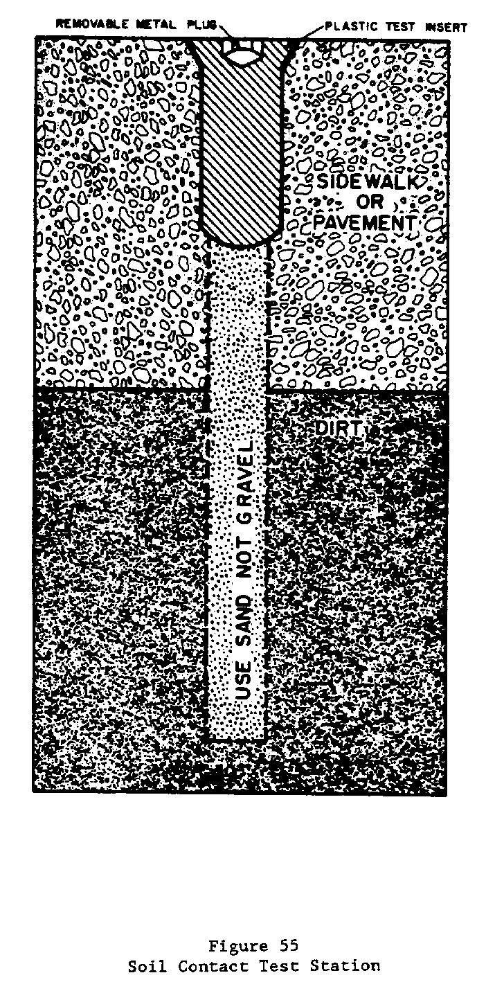
125
126 99
127 100
128 101
129 102
130 103
131 104
132 105
133
134 107
135 108
136 109
137 110
138 111
139 112 MIL-HDBK-1004/10
140 Section 7: SACRIFICIAL ANODE SYSTEM DESIGN 7.1 Theory of Operation. The basic principle of cathodic protection using sacrificial anodes is the electrochemical cell (refer to para. 2.2). As in the case of impressed current cathodic protection, high energy (potential) electrons are forced to flow from the anode to the structure to be protected. The structure-to-electrolyte potentials required for protection are identical to those for impressed current cathodic protection systems. These potential requirements are given in para The high potential electrons are generated through the corrosion of an active metal such as magnesium or zinc (refer to para. 3.2). In this type of system, the anode material is consumed, or sacrificed in the process, and the anodes must be periodically replaced in order to obtain continued protection. In order to minimize periodic anode replacement, sufficient anode material is normally provided so that the anode replacement interval is a desired number of years. Common practice for buried systems is to design the system for a 10- to 15-year anode life. For submerged systems, or for buried systems where anode replacement is difficult, longer (20- to 30-year) anode life is often used as a design criteria Advantages of Sacrificial Anode Cathodic Protection Systems. The primary advantage of sacrificial anode cathodic protection systems over impressed current cathodic protection systems is their simplicity and reliability. There are fewer critical components such as rectifiers in sacrificial anode systems. The critical cable from the anode to the impressed current anodes which is prone to failure is not a factor in sacrificial anode cathodic protection systems. The anode-to-structure cable in sacrificial anode systems is at a negative (protected) potential. Sacrificial anode cathodic protection systems are also in some cases less costly to install and maintain than impressed current cathodic protection systems. This is particularly true for systems with small current requirements (0.5 A or less per 100 lineal feet of structure). There are no power costs or costs associated with furnishing power at a remote site associated with sacrificial anode cathodic protection systems. Another major advantage of sacrificial anode cathodic protection systems is the nearly zero probability that interference problems will be experienced when this type of system is used. Sacrificial anode cathodic protection systems are commonly of the distributed anode type. This is usually necessary because of the limited driving potential of the anode materials used Disadvantages of Sacrificial Anode Cathodic Protection Systems. The primary disadvantages of sacrificial anode cathodic protection systems are associated with the limited driving potential between the structure and the anode materials used. This limits the current output of the anodes and restricts the area of structure which can be protected using a single anode. Anode consumption is also inherent in sacrificial anode systems and allowances for periodic anode replacement must be made. 7.2 Sacrificial Anode Cathodic Protection System Design Procedures. The basic principles for the design of sacrificial anode cathodic protection systems are described in para First, the total amount of current is determined, then the output per anode is determined. Then the number of anodes required and the life of the anodes is determined. If desired, the system parameters (anode size or type) are adjusted to give desired system performance, primarily to achieve desired anode life. 113
141 7.3 Determination of Current Required for Protection. The first step in the design of sacrificial anode type cathodic protection systems (refer to para ) is the determination of the total current required for the system. This fixes the current to be supplied by the sacrificial anodes. 7.4 Determination of Anode Output. The output of a single anode in the environment is determined. This may be determined by a simplified method which uses standard factors for the type and size of anode to be used and for the structure-to-electrolyte potential desired. Single anode output can also be determined by using the driving potential between the anode and the structure and the total circuit resistance. The anode-to-electrolyte resistance is a major factor in most cases. This method is essentially identical to the design procedure for impressed current systems Simplified Method for Common Situations. The formula given in para can be used to estimate the output of zinc or magnesium anodes in environments where the resistivity is above 500 ohm-cm. The following formula gives a good approximation of current output in many cases and can be used to check the results of the more detailed procedure outlined in para EQUATION: i = Cfy/P (21) where i = current output (ma) C = material constant f = size factor y = potential factor P = environmental resistivity Determination of Output Using Anode-to-Electrolyte Resistance. As in the case of impressed current systems, this method determines the total resistance of the cathodic protection circuit including anode-to-electrolyte resistance, structure-to-electrolyte resistance, and the resistance of all electrical connections and splices. Then, using the difference between the anode potential and the protected structure potential, the current output is determined using Ohm's Law Calculation of Anode-to-Electrolyte Resistance. As in the case of impressed current systems, the resistance between the anode and the environment is commonly the highest resistance in the cathodic protection circuit. This is particularly true when the anodes are located a small distance (10 feet or less) from the structure to be protected. The anode-to-electrolyte resistance can be calculated using simplified equations which are adapted to the most common situations, or the more complex but more general basic equations. 114
142 Simplified expressions for the determination of the anode-toelectrolyte resistance for a single vertical anode is given in para This formula is valid for sacrificial and impressed current anodes. The basic equations given in para are valid for sacrificial anode and impressed current systems. In some cases, it is desirable to use groups of two or three sacrificial anodes in order to provide the required current or anode life using stock size anodes. In this case, the paralleling factors given in para can be used to calculate the equivalent resistance of the anodes in parallel. In some cases where this method is used, an adjustable resistor or nichrome wire resistor is installed in the anode-to-structure cable to limit the current to the required value. In this case, the determination of the anode-to-electrolyte resistance is used to calculate the value of the resistor required Determination of Structure-to-Electrolyte Resistance. The structure-to-electrolyte resistance is commonly disregarded in the design of sacrificial anode cathodic protection systems since it is usually small with respect to the anode-to-electrolyte resistance Connecting Cable Resistance. The connecting cable resistance is determined by the size and length of cables used. The selection of appropriate wire sizes is described in para No. 12 AWG solid copper wires are commonly supplied on sacrificial anodes and No. 10 AWG wires are commonly used as connecting cables. These wires have a resistance of 1.02 and 1.62 ohms per 1,000 feet, respectively. Since connecting cables are short and currents are low in most sacrificial anode cathodic protection systems, connecting cable resistance can usually be neglected Resistance of Connections and Splices. The need to maintain low resistance throughout the life of the sacrificial anode cathodic protection system is more important than the initial resistance of connections. Although deterioration of connections in sacrificial anode cathodic protection systems is protected, the connections are still subject to corrosion resulting in increased resistance. As in the case of impressed current cathodic protection systems, the number of connections should be kept to an absolute minimum, and they should be very carefully assembled, insulated, inspected, and installed. The number and location of each connection should be installed per the system design and not at the discretion of the installer Total Circuit Resistance. The total circuit resistance (usually only the anode-to-electrolyte resistance is a major factor) is then determined by adding all of the resistances of the circuit elements Anode-to-Structure Potential. The potential difference between the anode and the protected structure is then determined. In most cases, the open circuit anode potential and a structure potential (for steel) of -850 mv versus copper/copper sulfate is used. Other structure potential criteria can be used as necessary. Use of an anode potential lower than the open circuit potential may be required when anode outputs are high as in very low resistivity environments Anode Output Current. The anode output current is then determined from the circuit resistance and the structure-to-anode potential using Ohm's Law. 115
143 7.4.3 Field Measurement of Anode Output. Calculations, as in the case of impressed current systems, can only give approximations of anode-toelectrolyte resistance under actual conditions. While these calculations can be used for an initial system design, the actual anode output encountered is often sufficiently different from the calculated value to require adjustment or modification of the system. This is more of a problem for sacrificial anode systems than for impressed current systems since the output potential is not adjustable in sacrificial anode systems. In areas where the soil resistivity varies with location, a field measurement must be made at each anode location. Often the only remedy for low anode output is to add additional anodes to the system. High anode output can be remedied by installing current limiting resistors in the anode lead wires, but this should be avoided where possible. The actual anode output can best be determined by actual field measurements. Anode output is best determined by installing an anode at the actual site of the installation and attaching it to the structure to be protected. The anode output is measured using a current shunt (0.01 or 0.1 ohm) installed in the anode lead wire. As a single anode is unlikely to polarize the structure to the desired potential, correction of the anode output for structure potential is usually required. This can be done using the structure potential factor in the simplified equation given in para , or by determining the anode-to-electrolyte resistance based upon the actual potential difference achieved and the anode output current. 7.5 Determination of Number of Anodes Required. After the output per anode is determined, the number of anodes required for protection is calculated. This is done by dividing the total output by the output per anode. In practice, approximately 10 percent more anodes are installed to allow for inaccuracies in system design, seasonal variations in anode output, and decreased anode output as the anodes are consumed. Installation of a limited percentage of additional anodes is not wasteful because, if the system is properly adjusted, additional anodes simply result in longer anode life. 7.6 Determination of Anode Life. The anode life is calculated based upon the current flow, anode weight, and anode efficiency. The calculation involves the number of ampere hours produced by an anode per pound on anode material consumed. Anode consumption can be calculated using the formula: EQUATION: W = YSI (22) where W = anode consumption in pounds Y = number of years S = anode consumption rate in lbs/a yr based upon actual anode efficiency I = current output in amperes 116
144 For some anode materials, the anode efficiency is dependent upon anode current density as shown in Figure 73. For these materials, the anode consumption can be calculated using the formula: EQUATION: W = YSI/E (23) where W = anode consumption in pounds Y = number of years S = theoretical anode consumption rate in lbs/a yr I = current output in A E = anode efficiency For the standard alloy magnesium material, the anode efficiency is essentially constant above 250 ma/ft² of anode area. If the anode efficiency is low at the anode current density at which it is operated, anode material is wasted due to self corrosion. At an anode efficiency of 50 percent, one-half of the anode material is consumed by self corrosion and one-half is consumed in providing protective current. If the desired anode life is not obtained using an initially selected anode material and size, a different sized anode or one of a different material is substituted and the process repeated in an iterative manner until a system with the desired characteristics is obtained. 7.7 Seasonal Variation in Anode Output. Anode output will vary as the resistivity of the environment changes. Seasonal variations associated with soil moisture in buried systems or seawater dilution in estuaries may result in changes in anode output. Fortunately, in most cases the current required for protection is also reduced when the resistivity of the environment increases so that this effect is partially self compensating. In some cases, however, anode output will fall below or above the limits for protection and the system will require seasonal adjustment or augmentation in order to provide adequate protection. 7.8 Sacrificial Anode Materials Magnesium. Magnesium is the most commonly used sacrificial anode material for the protection of buried structures. Magnesium anodes are also used for the protection of the interiors of water tanks and heaters, heat exchangers and condensers, and waterfront structures. Magnesium anodes are available as castings and extrusions weighing from 1 to 200 pounds, and in a wide variety of shapes (refer to para ). Two anode compositions are commonly used. They are the standard alloy and a "high potential" alloy. The composition of each alloy is given in para
145
146 Potentials. The open circuit potential of the standard alloy is approximately V versus copper/copper sulfate. The open circuit potential of the high potential alloy is approximately V versus copper/copper sulfate Sizes. Magnesium anodes are available in a wide variety of sizes and shapes as shown in Tables 12 through 17. In addition to the sizes shown, magnesium alloy anode material is available as a "ribbon" anode which consists of a 10-gauge steel wire surrounded by standard alloy magnesium 3/8 by 3/4 inch. Magnesium ribbon anodes are used in situations such as inside casings where the space available is limited, or to protect small diameter utility cables Current Output. Current output from magnesium anodes should be determined from the formulae in para or by field measurement as described in para Backfill. For soil installations, the use of backfill is highly desirable and is required in all cases. Composition of typical backfill material for use with magnesium anodes is given below: Composition of Backfill for Magnesium Anodes Gypsum 75% Bentonite 20% Sodium Sulfate 5% Anodes are available in prepackaged permeable cloth bags filled with prepared backfill. Prepackaged anodes are commonly supplied with an outer impermeable wrapping such as plastic. The impermeable wrapping must be removed from these anodes prior to installation Zinc. Zinc anodes are commonly available in weights from 5 pounds to 250 pounds in the form of plates, bars, and rods as described in Tables 18 through 21. Zinc is also available as ribbon anodes in 5/8- by 7/8-inch, 1/2- by 9/16-inch, and 11/32- by 15/32-inch sizes, each with a 1/10-inch-diameter galvanized steel wire core. Zinc anodes are most commonly used in immersion service either in fresh or salt water. They are, however, occasionally used in the protection of buried structures when special circumstances are encountered. Two zinc anode compositions are commonly available. They are a standard alloy formulated for use in fresh water and soil and an alloy specially formulated for use in seawater. The composition of these alloys is given in para
147 Table 12 Standard Alloy Magnesium Anodes - Standard Sizes for Use in Soil WEIGHT SIZE PACKAGED PACKAGED SIZE (lb) (in.) WEIGHT (lb) (in.) 3 3 x 3 x x x 3 x x x 3 x x x 1.5 x x 4 x x x 2 x x 4 x x x 3 x x 5 x 20-1/ x x 3 x x 5 x x 7 x x x x x 4 x Most common size used. NOTE: Core material for soil anodes is a galvanized, open pitch, spiral-wound strip 3/8-inch inside diameter (id), 1/2-inch outside diameter (od). Connecting wire for soil anodes is a 10-foot length of single-strand No. 12 American Wire Gage (AWG) thermoplastic waterproof (TW) insulated copper wire, silver-soldered to the core with the joints sealed against moisture. Special connecting wires or lengths other than 10 feet are available. 120
148 Table 13 Standard Alloy Magnesium Anodes - Standard Sizes for Use in Water WEIGHT SIZE TYPE OF CORE (lb) (in.) x 3.5 x 26 3/4-in. diam galvanized pipe core, flush ends x 7 x 16 Threaded 3/4-in. diam galvanized pipe extending 1 inch both ends, flush ends optional x 7 x 16 1/2-in. diam galvanized eyebolt core x 16 3/4-in. diam galvanized pipe core, flush ends x 16 1/2-in. diam galvanized eyebolt core x 7 x 32 3/4-in. diam galvanized pipe core, flush ends x 7 x 32 1/2-in. diam galvanized eyebolt core x 32 3/4-in. diam galvanized pipe core, flush ends x 32 1/2-in. diam galvanized eyebolt core. Table 14 Standard Alloy Magnesium Anodes - Standard Sizes for Condensors and Heat Exchangers WEIGHT SIZE TYPE OF CORE (lb) (in.) 15 4 x 8 x 8 3/4-in. bolt 24 2 x 9 x 18 1/4- x 2-in. straps 44 4 x 9 x 18 1/2- x 2-in. straps 60 7 x 9 x 18 3/4-in. bolt 121
149 Table 15 Standard Alloy Magnesium Anodes - Elongated WEIGHT SIZE PACKAGED PACKAGED SIZE (lb) (in.) WEIGHT (lb) (in.) x x x x x x x x x x x x x x 52 Table 16 High Potential Alloy Magnesium Anodes - Standard Sizes for Soil and Water WEIGHT SIZE PACKAGED PACKAGED SIZE (lb) (in.) WEIGHT (lb) (in.) x 3.75 x x x 3.75 x x x 2.75 x x x 3.75 x x x 3.75 x x x 2.75 x x x 3.75 x x x 2.75 x x x 3.75 x x x 2.5 x x x 4.5 x x x 5.5 x x x 3.75 x x x 5.5 x x x x x 4.5 x NOTE: Core material is a galvanized 20-gauge perforated steel strip. Anodes longer than 24 inches have a 9-gauge core. The connecting wire is a 10-foot length of solid No. 12 AWG TW insulated copper wire, silver-soldered to the core with joints sealed against moisture. Special wires or other lengths are available. 122
150 Table 17 Standard Alloy Magnesium Anodes - Standard Size Extruded Rod for Water Tanks and Water Heaters WEIGHT PER SIZE TYPE OF CORE FOOT (lb) in. diam x 1 ft to 20 ft 1/8-in. diam steel rod in. diam x 1 ft to 20 ft 1/8-in. diam steel rod in. diam x 1 ft to 20 ft 1/8-in. diam steel rod in. diam x 1 ft to 20 ft 1/8 -in. diam steel rod in. diam x 1 ft to 20 ft 1/8 - in. diam steel rod in. diam x 1 ft to 20 ft Table 18 Zinc Anodes - Standard Sizes for Underground or Fresh Water WEIGHT NOMINAL (lb) SIZE (in.) x 1.4 x x 1.4 x x 1.4 x x 1.4 x x 2 x x 2 x x 2 x 60 NOTE: Core for standard anodes shown is 1/4-inch diameter electrogalvanized mild steel rod. 123
151 Table 19 Zinc Anodes - Special Sizes for Underground or Fresh Water WEIGHT SIZE (in.) LENGTH (in.) (lb/in.) x 3 6 to x 4 6 to x 5 6 to x 7 6 to x 9 12 to x 10 9 to 24 NOTE: Core is 1/4-inch diameter electro-galvanized mild steel rod. Also available in 3/8-inch, 1/2-inch, or 5/8-inch diameters. Table 20 Zinc Anodes - Standard Sizes for Use in Seawater WEIGHT (lb) SIZE (in.) x 3 x x 3 x x 6 x x 2 x x 4 x x 9 x x 4 x 60 NOTE: The 24-pound and smaller anodes have galvanized steel mounting straps. The 50-pound size has a 3/8-inch diameter galvanized steel rod for core. Larger sizes have 3/4-inch or 1-inch diameter galvanized steel pipe cores. 124
152 Table 21 Zinc Anodes - Special Sizes for Use in Seawater WEIGHT SIZE (in.) LENGTH (in.) (lb/in.) x to x 2 6 to x 3 6 to x 4 6 to x 5 6 to x 7 6 to x 9 9 to x 10 9 to x 10 9 to 24 NOTE: A variety of cores are available with the different sizes Composition. The compositions of the standard zinc alloy and the alloy formulated for use in seawater are given below: 1 2 Element Standard Alloy Seawater Alloy Aluminum 0.005% max % Cadmium 0.003% max % Iron % max 0.005% max Lead 0.003% max 0.006% max Copper % max Silicon % max Zinc Remainder Remainder 1 Specification ASTM B-148, Type II 2 Specification ASTM B-148, Type I; or MIL-A-18001H Anode Efficiency. The theoretical anode consumption for zinc is 23.5 lbs/a yr or 372 ampere hours per pound (A hr/lb). The efficiency of zinc is greater than that of magnesium. The efficiency of zinc is commonly 90 percent to 95 percent regardless of current output. For design purposes, 90 percent is used for the efficiency of zinc Potentials. The open circuit potential of both commonly used zinc anode materials is V in most soils or natural waters. The relative potential between zinc and iron is dependent upon temperature. At temperatures above ambient, the potential difference between the two materials is reduced. In some fresh waters, the potential can reverse at temperatures above 140 degrees F. Zinc should not be used to protect steel in such cases as hot water heaters Sizes. Both standard alloy and seawater type zinc anodes are available in a wide variety of sizes and shapes. Anodes used in soil usually have a galvanized mild steel rod core. This core is attached to the anode cable during installation of the anode. In both fresh water and seawater applications the anode is often attached directly to the structure to be protected by welding or bolting the steel rod, pipe, or strap core to the 125
153 structure. When suspended in water, the core is extended by welding on a steel extension. For suspended systems, the use of a cable continuity bond is recommended to insure that the resistance between the anode and the structure is minimized. Sizes and shapes of commercially available zinc alloys for cathodic protection are given in Tables 16 through 19. In addition, zinc ribbon anodes 5/8 by 7/8 inch weighing 1.2 pounds per foot (lb/ft) for seawater use are available. Two sizes of zinc ribbon anodes are available in the standard alloy: 1/2 by 9/16 inch weighing 0.6 lb/ft, and 11/32 by 15/32 inch weighing 0.25 lb/ft. All three of these commercially available zinc ribbon anodes have a 1/10-inch steel core Current Output. The current output of zinc anodes may be determined either by the calculations outlined in para or by field measurements as described in para When used without backfill, zinc anodes can become covered with nonconductive corrosion products which can reduce their current output. Seawater alloy anodes are specially formulated to reduce this tendency in seawater. When used in soil containing high levels of oxygen, carbonates, or phosphates, backfill should be used with zinc anodes in order to reduce the possibility of the buildup of these corrosion products Backfill. Two typical compositions of backfill used with zinc anodes in soils are given below: Material Type 1 Type 2 Hydrated gypsum 75% 50% Bentonite 20% 50% Sodium sulfate 5% Aluminum. Aluminum sacrificial anodes are a more recent development than either zinc or magnesium alloys. Their primary use is in the protection of structures in seawater. However, there is a potential for their use in fresh water or in soil. When the original anodes used are aluminum alloy and their performance has been satisfactory they should be replaced with anodes of the same type. Early formulations of aluminum alloys for use as a sacrificial anode contained mercury. While the amount of mercury contained in the alloy is small, the mercury tends to concentrate in the anode stubs which remain after the bulk of the anode has been consumed. Precautions should be taken during removal of the stubs, especially by methods which generate heat, to prevent mercury poisoning. Mercury containing aluminum alloy anode stubs must be disposed of properly. 126
154 Composition. The compositions of most aluminum alloy anodes are proprietary. Typical compositions of three proprietary alloys are given below: Element Type I Type II Type III Zinc 0.35% % 3.5% - 5.0% 3.0% Silicon 0.10% max - 0.1% Mercury 0.035% % 0.035% % - Indium % Aluminum Remainder Remainder Remainder The Type I alloy is formulated for submersion in full strength seawater. The Type II alloy is formulated for use when the anode may become immersed in bottom sediments. The Type III alloy is formulated for use in bottom sediments, full strength seawater, or in brackish water Anode Efficiency. Type I aluminum anodes have a consumption rate of approximately 1,250 A hrs/lb or 6.8 lbs/a yr. Type II aluminum anodes in bottom sediments have a reduced efficiency and a consumption rate of approximately 770 A hrs/lb or 11.4 lbs/a yr. Type III aluminum anodes have a consumption rate of approximately 1,150 A hrs/lb or 7.6 lbs/a yr Potentials. The potential of Type I and Type II aluminum anodes is V versus copper/copper sulfate. Type III anodes have a slightly higher driving potential of V versus copper/copper sulfate Sizes. Aluminum alloy anodes have been developed primarily for the protection of marine structures. They are available in a wide variety of sizes and shapes as shown in Tables 22 through 26. The bracelet anodes described in Table 24 are shown in Figure 74. These bracelet anodes are used for the protection of submerged pipelines and may also be used on pipe pilings Current Output. The current output of aluminum anodes can be determined either by the calculations outlined in para or by field measurements as described in para The current output for some sizes of aluminum anodes is provided by anode manufacturers and is calculated using an assumed structure potential of -850 mv versus copper/copper sulfate and an environmental resistivity of 20 ohm-cm. These values should be considered as estimates only and should be verified by calculations of tests. 7.9 Other System Components Connecting Wires. Proper selection of cable size, type of insulation, and routing is necessary for proper and reliable system operation. Only copper cables should be used in any cathodic protection installation. High connection resistances and difficulty in making welded connections associated with the use of aluminum wires precludes their use in cathodic protection. 127
155 128
156 129
157 130
158 131
159 132
160
161 As connecting wires in sacrificial anode cathodic protection systems are themselves cathodically protected, insulation is not as critical as in portions of impressed current cathodic protection systems. Type TW, Type RHW-USE, or polyethylene insulation may be used. Anode lead wires should never be used to suspend, carry, or install the anode. Anode cables are commonly No. 12 AWG with Type TW insulation. Unless otherwise necessary, other connecting wires should be No. 12 AWG solid copper for single anodes. When currents larger than 1 A flow in any portion of a sacrificial anode circuit, the most economic wire size should be determined using the methods outlined in para Instead of the cost of power used in the determination of economic wire size for impressed current cathodic protection systems, the cost of additional anodes to overcome the resistive losses should equal the annual fixed costs for the cable size being analyzed Connections and Splices. Wire splices and connections (refer to para ) should be kept to an absolute minimum and the type of connection used should have both low resistance, high reliability, and good resistance to corrosion. Connections should be made using either exothermic or mechanical connections (refer to para. 10.6). Insulation of underground connections should be made by using encapsulation in epoxy or insulation with hot coal-tar enamel followed by wrapping with pipeline felt. Above grade connections, such as in test stations, are usually mechanical connections and should be carefully taped in order to prevent corrosion due to the entry of moisture. systems: a) The following connections are required for sacrificial anode (1) Connection between anode(s) and structure. (2) Connection between cable and anode (usually factory made or connection is attached to cast-in-core) (3) Necessary bonds and test wires The need for additional connections and splices should be carefully evaluated. As in the case for impressed current systems, the location of all necessary splices and connections should be specifically shown on the design drawings. The need for additional splices and connections should be determined by the designer of the system and not left to the discretion of the installer Bonds and Insulating Joints. Bonds and insulating joints are required for some sacrificial anode cathodic protection systems. Guidelines presented in paras and should be used for all bonds and insulating joints Test Station Location and Function. The most common type of test station used in sacrificial anode cathodic protection systems is the currentpotential test station shown in Figure 75. In this test station, the anode lead wire is connected to the structure lead using a 0.01-ohm resistor (shunt) which is used to measure the current output by measuring the voltage drop across the shunt. The second structure lead is used to measure the structure potential using a noncurrent carrying connection thus eliminating any potential drop along the conductor. The second structure connection can also 134
162 be used as a spare if the primary structure connection is damaged. Test stations for sacrificial anode cathodic protection systems can either be the flushmounted or above grade type as described in para If flush-mounted test stations are used, the soil exposed in the bottom of t test station can be used to measure the structure-to-electrolyte potentia Location of such test stations directly over the structure is often advantageous as any IR drops due to current flowing through the soil are minimized. Other test stations used in sacrificial anode cathodic protection systems are: the potential test station, the soil contact tes station, the line current (IR Drop) test station, the insulating joint te station, the casing insulation test station, and the bond test station. These test stations are identical to those described in para Backfill. The use of backfill in soil applications for the ty of anode materials used in sacrificial anode cathodic protection systems described in the section on each anode material. When prepackaged anodes are used, the impermeable wrapping must be removed from these anodes prio to installation.
163 Section 8: TYPICAL CATHODIC PROTECTION SYSTEMS 8.1 Diagrams of Cathodic Protection Systems. In Figures 76 through 96, typical cathodic protection system installations are shown. Features of these designs may be applicable to the design of similar systems with similar applications. Note: The design for each specific application must be made based upon actual conditions and requirements. Section 9 provides analytical examples of the designs of sample cathodic protection systems. 137
164
165 139
166 140
167 141
168
169
170 144
171 145
172
173 147
174
175 149
176 150
177 151
178 152
179 153
180 154
181 Section 9: CATHODIC PROTECTION SYSTEM DESIGN EXAMPLES 9.1 Introduction. The following examples illustrate the application of the design principles outlined in Sections 4, 6, and 7. They are intended to illustrate the design methods to be used and are not standard designs. In these examples, interference to or from foreign structures is not considered. In practice, the design should be based upon field measurements whenever possible and not on calculated estimates. In some examples, more detailed and rigorous calculations than actually required are presented for illustrative purposes. Shorter, more simplified calculations would give equally applicable estimates, but should only be used once the basic concept of the process is understood. It must be remembered that all cathodic protection system designs make many assumptions, such as uniform environmental resistivity, which may or may not prove to be true. When the system is installed, it will require adjustment and possible modification in order for effective protection to be achieved. In congested areas, interference problems are often difficult to correct and optimum levels of protection may not be practically achieved. In such cases, cathodic protection will reduce the incidence and degree of corrosion damage but corrosion may not be entirely eliminated. Twelve examples are provided: a) Elevated steel water tank. b) Elevated steel water tank where ice is expected. c) Steel gas main. d) Natural gas distribution system. e) Hot water storage tank. f) Underground steel storage tank. g) Steam heat distribution system. h) Aircraft multiple hydrant refueling system. i) Steel sheet piling in seawater (galvanic anodes). j) Steel sheet piling in seawater (impressed current). k) Steel H piling in seawater (galvanic anodes). l) Steel H piling in seawater (impressed current). 9.2 Elevated Steel Water Tank. This impressed current design is for a tank that has not been built; hence, it is not possible to determine current requirements, etc., by actual measurement. Calculated estimates are used. 155
182 9.2.1 Design Data a) Tank capacity - 500,000 gallons b) Tank height (from ground to bottom of bowl) feet c) Diameter of tank - 56 feet d) High water level in tank - 35 feet e) Overall depth of tank - 39 feet f) Vertical shell height - 11 feet g) Riser pipe diameter - 5 feet h) Shape of tank - Ellipsoidal, both top and bottom i) All internal surfaces are uncoated j) Design for maximum current density - 2 ma/ft² k) Electric power available 120/240 V ac, single-phase l) String-type HSCBCI anodes are used m) Design life - 10 years n) Water resistivity - 4,000 ohm-cm o) Tank water must not be subject to freezing p) Assumed deterioration rate lbs/a yr q) Anode efficiency (assumed) - 50 percent Computations a) Area of wetted surface of tank bowl (see Figure 97): (1) Top section (T): where A = 2 B rx (approximate) T r = 28 feet (radius of tank) x = 10 feet A = 2 x x 28 x 10 ft² A T = 1759 ft² T 156
183 BOTTOM SECTION Figure 97 Segmented Elevated Tank for Area Calculations (2) Center section (C): where r = 28 feet (radius of tank) h = 11 feet A c = 2 x x 28 x 11 ft 2 A c = 1,935 ft 2 (3) Bottom section (B): where r = a = 28 feet (radius of tank) 14 feet 157
184 A = %&& 2 x x 28 x %&&&&&&&&& 14² + 28² B A = 3,894 ft² B (4) Therefore: A = 1,759 ft² T A = 1,935 ft² C A = 3,894 ft² B (5) Total = 7,588 ft² (wetted area of tank bowl). b) Area of riser pipe: where A = 2Br h R R R r = 2.5 feet (radius of riser) R h = 115 feet (height of riser) R A = 2 x x 2.5 feet x 115 feet R A = 1,806 ft² R c) Maximum design current for tank: I = 2.0 ma/ft² x 7,588 ft² T I = 15,176 ma or 15.2 A T d) Maximum design current for riser: I = R 2.0 ma/ft² x 1,806 ft² I = R 3,612 ma or 3.6 A e) Minimum weight of tank anode material: where W = YSI/E W = weight of anode material Y = design life S = anode deterioration rate I = maximum design current E = anode efficiency 158
185 where Y = 10 years S = 1.0 lbs/a yr E = 0.50 I = 15.2 A W = 10 x 1.0 x 15.2/0.50 lb W = 304 pounds f) Minimum weight of riser anode material: where W = YSI/E Y = 10 years S = 1.0 lbs/a yr I = 3.62 A E = 0.50 W = 10 x 1.0 x 3.62/0.50 lb W = 72.4 lb g) Radius of main anode circle: where r = (DN)/2(B+N) D = 56 feet N = 10 (assumed number of anodes) r = 56 x 10/2( ) r = 560/26.28 r = 21.3 feet, use 22 feet h) Spacing of main anodes. Generally the distance from the anode to the tank wall and tank bottom is about equal; this distance should be about one-half the circumferential distance between anodes. (1) Circumferential spacing: C = (2Br)/N where r = 22 feet (radius of anode circle) N = 10 (assumed number of anodes) C = 2 x x 22/10 C = 13.8 feet, use 14 feet (2) Cord spacing is approximately the same as circumferential spacing: 14 feet will be used (see Figure 98). 159
186
187 type C or type CDD. Type CDD is recommended because the lead wire connection is protected longer by the thicker wall of the enlarged ends. Two type CDD anodes per string provide a current capacity of 2 A x 10 strings = 20 A. These anodes are spaced as shown in Figure 99. NOTE: The anodes chosen in this example were chosen to show the analogy that must be used in designing cathodic protection. With the advent of newer center connected tubular anodes, anode type TAFW, 2-3/16 inch by 8 inch, weighing 4.3 pounds each, should be used instead of CDD anodes. Table 27 Technical Data - Commonly Used HSCBCI Anodes ANODE WEIGHT ANODE MAX. AREA MAX. CURRENT TYPE SIZE (in.) (lb) DISCHARGE (ft²) DENSITY (A) (A/ft²) TA-FW 2-3/16 x FW 1-1/8 OD x FC 1-1/2 x G-2 2 OD x G-2-1/2 2-1/2 x ,4 B 1 x C 1-1/2 x CDD 1-1/2 x M 2 x SM 4-1/2 x K-6 6 x 2-1/ K x 3-7/ B-30 1 x TA-2 2-3/16 x For elevated fresh water tank. 2 For distributed system in ground trench. 3 Each end enlarged with cored opening for wire. 4 Not more than 2 anodes per assembly. 161
188 162
189 (4) Anode current density is computed as follows: Output = 15.2/2 x 10 x 2 = 0.38 A/ftÀ2Ù j) Resistance of main anodes: where R = (0.012P log D/a)/L P = 4,000 ohm-cm D = 56 feet L = 2 x 5 feet = 10 feet a = 44 x = 12.1 feet (0.275-equivalent diameter factor from curve) (see Figure 100) R = (0.012 x 4,000 log 56/12.1)/10 R = 48 log 4.628/10 R = 3.19 ohms
190 (1) However, the L/d ratio of two 1-1/2-inch diameter by 60-inch long anodes in tandem is less than 100 and thus the fringe factor must be used. L/d = (2 x 60)/1.5 L/d = 80 < 100 (2) The fringe factor from curve Figure 101 corresponding to L/d ratio is k) Stub anodes: R (adjusted) = 3.19 x 0.95 R = 3.03 ohms (1) In the design of an elevated water tank, the need for stu anodes must be justified. The main anode radius has been calculated to b 22 feet. The main anodes are spaced to provide approximately the same distance from the sides and the bottom of the tank. The main anodes will protect a length along the tank bottom equal to 1-1/2 times the spacing o the anode from the bottom. (2) The anode suspension arrangement for the tank under consideration is shown in Figure 99. Thus, it can be seen that stub anod are required for this design. Ten stub anodes are arranged equally space on a circumference that has a radius of 8 feet in a manner illustrated in Figure 98. For smaller diameter tanks, stub anodes may not be required.
191 l) Current division between main and stub anodes: Figure 99): (1) Area of tank bottom protected by stub anodes (see 2 2 As = B(r - r ) 2 1 where r = 13 feet (radius of protected segment) 2 r = 2.5 feet (radius of riser) 1 A = ( ) s A = x s A = ft² s (2) Maximum current for stub anodes: I = 2.0 x I s = ma or 1.02 A s (3) Maximum current for tank bowl = 15.2 A. (4) Maximum current for main anodes: I = m I = 14.2 A m m) Rectifier voltage rating: (1) Electrical conductor to main anodes. Wire size No. 2 AWG, ohm/1,000 feet (refer to Table 10), estimated length 200 feet: R = 200/1000 x = (2) Voltage drop in main anode feeder: E = IR where I = 14.2 A R = ohm E = 14.2 x E = 0.45 V E = IR (3) Voltage drop through main anodes: 165
192 where I = 14.2 A R = 3.03 ohms E = 14.2 x 3.03 E = 43.0 V (4) Total voltage drop in main anode circuit: E = T E = or 45 V T Use a multiplying factor of 1.5, or 67.5 V. (5) The nearest commercially available rectifier meeting the above requirement is a single-phase, 80-V unit. n) Selection of stub anodes. Because it is desirable to use as small an anode as possible without exceeding the manufacturers' recommended rate, try using type FC, HSCBCI anode measuring 1-1/2-inch by 9 inches. Use one anode per string as shown in Figure 99. Anode current density is computed as follows: Output = 1.02/(10 x 0.03) = 0.34 A/ft² Because this exceeds the recommended maximum anode current density (refer to Table 27), the type B anode is the best choice. o) Resistance of stub anodes: R = 0.012P log D/a/L where P = 4,000 ohm-cm D = 56 feet L = 5 feet a = 16 x = 4.4 feet (factor from Figure 100) R = (0.012 x 4,000 log 56/4.4)/5 R = 48 log 12.73/5 R = 48 x 1.105/5 R = 10.6 ohms L/d = 60/1 = 60<100 Fringe factor from curve Figure 101, 0.90 R (adjusted) = 10.6 x 0.90 = 9.54 ohms p) Voltage drop in stub anode circuit: (1) Electrical conductor to stub anodes. Wire size No. 2 AWG, ohms/1,000 feet (refer to Table 10), estimated length 200 feet: R = (200/1,000) x = ohm 166
193 E = IR where (2) Voltage drop in stub anode feeder. I = 1.02 A R = ohm E = 1.02 x E = V (3) Voltage drop in anode suspension conductors. Estimated length 50 feet, No. 2 AWG (refer to Table 10), ohms/1,000 feet: R = (50/1,000) x = ohm E = IR where I = 1.02/10 = A R = ohm E = 1.02 x E = negligible (4) Voltage drop through stub anodes: E = IR where I = 1.02 A R = 9.54 ohms E = 1.02 x 9.54 E = 9.73 V (5) Total voltage drop in stub anode circuit. E = I E = 9.76 V T (6) Since the stub anode voltage is below the 45 V calculated for the main tank anode circuit, the necessary current adjustment can be accomplished through a variable resistor in the stub anode circuit. q) Stub anode circuit variable resistor: (1) Criteria for variable resistor. The resistor should be capable of carrying the maximum anode circuit current and have sufficient resistance to reduce anode current by one-half when full rectifier voltage is applied to the anode circuit. 167
194 (2) Stub anode circuit data: Rectifier output = 80 V Anode current = 1.02 A Anode resistance = 9.54 ohms (3) Variable resistor rating: R = E/I where E = 80 V I = 1.02/2 or 0.51 A R = 80/0.51 R = ohms Ohmic value of resistor = = ohms Wattage rating of resistor, (1.02)² x = W The nearest commercially available resistor size meeting the above requirements is a 175-W, 200-ohm, 1-A resistor. r) Resistance of riser anodes. In order to get the maximum desired current in the riser (3.62 A), the resistance limit is calculated as follows: where R = E/I E = V I = 3.62 A R = 43.5/3.62 R = 12.0 ohms s) Riser anode design: (1) Type FW (1-1/8-inch by 9-inch) string type anodes cannot be used in the riser because the maximum anode current discharge of A per anode would be exceeded. The number of type FW anodes required would be 145 and continuous throughout the riser. This is excessive. The best choice of anode for a flexible riser string is the type G-2 (2-inch by 9-inch) highsilicon cast iron anode. (2) Number of units required: R = (0.012P log D/d)/L L = (0.012P log D/d)R 168
195 where P = 4,000 ohm-cm D = 5 feet d = 2 inches or feet R = 12 ohms L = (0.012 x 4,000 log 5/0.166)12 L = (48 x log 30.1)/12 L = (48 x 1,479)/12 L = 5.92 feet Number of units = 5.92/0.75 = 7.9 or 8 units In order to get proper current distribution in the riser pipe, the anode units should not be placed too far apart. It is generally considered that each anode unit protects a length along the riser pipe equal to 1-1/2 times the spacing of the anode from the riser pipe wall. Riser height = 115 feet Spacing (center of anode to tank wall) = 2.5 feet Length of riser protected by one anode = 1.5 x 2.5 = 3.75 feet Number of units required = 115/3.75 = 30.7 or 31 units. To satisfy the maximum anode discharge current for a G-2 anode: 3.62 A/0.1 amp = 36 Therefore, 36 anodes are needed instead of 31 or 8. (3) Anode resistance based on the use of 36 anode units: R = (0.012P log D/d)/L where P = 4,000 ohm-cm D = 5 feet d = 2 inches or feet L = 36 x 9 inches = 324 inches or 27 feet R = (0.012 x 4,000 log 5/0.166)/27 R = 48 log 30.1/27 R = 2.63 ohms L/d ratio for the riser anode string is 324/2 or 162; thus no fringe factor correction is applied. t) Voltage drop in riser anode circuit: (1) Electrical conductor to riser anodes. Wire size No. 2 AWG, ohms/1,000 feet (refer to Table 10), estimated length 200 feet: R = 200/1,000 x = ohm 169
196 (2) Voltage drop in riser anode feeder: E = IR where I = 3.62 A R = ohm E = 3.62 x E = V (3) Voltage drop in riser anode suspension cables. Wire size No. 2 AWG, ohm/1,000 feet (refer to Table 10), estimated length 130 feet: R = 130/1,000 x = 0.02 ohm E = IR where I = 3.62/2 = 1.81 A average (single current does not flow the full length of the anode string) R = 0.02 ohm E = 1.81 x 0.02 E = 0.04 V E = IR where (4) Voltage drop through riser anodes: I = 3.62 A R = 2.63 ohms E = 3.62 x 2.63 E = 9.52 V (5) Total voltage drop in riser anode circuit: E = T E = 9.69 V T u) Riser anode circuit variable resistor: (1) Criteria for the variable resistor are the same as given for the stub anode resistor. (2) Riser anode circuit data: Rectifier output, 80 V Anode current, 3.62 A Anode resistance = = 2.68 ohms 170
197 (3) Variable resistor rating: R = E/I where E = 80 V I = 3.62/2 = 1.81 A R = 80/1.81 R = 44.2 ohms Ohmic value of resistor = = 41.5 ohms. Wattage rating of resistor = (3.62)² x 41.5 = W (Resistor should reduce anode current by one-half when fullrectifier voltage is applied.) The nearest commercially available resistor size that meets the above requirements is a 750-W, 50-ohm, 3.87-A resistor. This rheostat is 10 inches in diameter and 3 inches in depth, and fairly expensive. This rheostat will not fit into most rectifier cases. In addition, the power consumed by the rheostat is considerable. This power creates substantial heat that may damage components within the rectifier case unless adequate ventilation is provided. The problems associated with using a large rheostat can be eliminated by using a separate rectifier for the riser anodes. Although initial cost may be slightly high, power savings will be substantial and damage by heat will be avoided. v) Sizing rectifier for riser: (1) Requirements: dc current output = 3.62 A Anode circuit resistance = 2.68 ohms dc voltage required = IR = 3.62 x 2.68 E = 9.70 V (2) Rectifier rating. Standard ratings for a rectifier in this size class are 18 V, 4 A. w) Rectifier dc rating for bowl. Voltage output as previously determined, 80 V. Current rating is 15.2 A. The nearest commercially available rectifier meeting the above requirements is 80 V, 16 A. x) Wire sizes and types. All positive feeder and suspension cables (rectifier to anodes) must be No. 2 AWG, HMWPE insulated copper cable. To avoid complication, the negative rectifier cable (rectifier to structure) must be the same size and type (see Figure 102). y) Discussion of the design: (1) The design points out the disadvantages of achieving corrosion control through cathodic protection without the aid of a protective coating. When the interior of a tank is coated, the current requirement is 171
198 reduced from 60 to 80 percent. On large tanks without coating, larger si and more expensive anodes, wire, and rectifier units must be used. In addition, the power consumed by the uncoated tank is far greater. These additional costs usually exceed the cost of a quality coating system over 10-year period. Corrosion above the water line of a water storage tank i usually severe because of the corrosive nature of condensation. For this reason, protective coatings must be used above the water line on both lar and small water storage tanks to mitigate corrosion. 172
199 (2) For further assistance and guidance in the design of cathodic protection systems for elevated cold water storage tanks, see Figures 102 through 104. (3) The HSCBCI anodes were selected for this particular design purely for illustrative purposes. It does not mean that this material is superior to other types of anode material. Other acceptable anode materials include aluminum and platinized titanium or niobium. With the advent of newer tubular center connected anodes, the designer should choose these anodes over the end connected in most cases because of their higher current capability and longer life. (4) For this design, silicon cells should be specified for the rectifier that protects the bowl and selenium cells should be specified for the rectifier that protects the riser. Silicon cells operate more efficiently at high dc output voltages than selenium cells do but require elaborate surge and overload protection. This protection is not economical in the low power consuming units. A guide for selection of rectifying cells is as follows: Use silicon cells for single-phase rectifiers operated above 72 V dc or three-phase rectifiers operated above 90 V dc. Use newer nonaging selenium for single-phase rectifiers operated below 72 V dc or three-phase rectifiers operated below 90 V dc. 9.3 Elevated Water Tank (Where Ice is Expected). Impressed current cathodic protection is designed for an elevated water as shown in Figure 105. The tank is already built, and current requirement tests have been made. Anodes must not be suspended from the tank roof, because heavy ice (up to 2 feet thick) covers the water surface during winter. The weight of this ice could not be tolerated on the anode cables, so another method of support is used. Button anodes must be mounted on the floor of the tank and lightweight platinized titanium anodes must be suspended in the riser from the tank bottom. 173
200 Water Tank and Figure 104: Riser Anode Suspension Detail for Elevated W
201
202 9.3.1 Design Data a) Tank height (from ground to bottom of bowl) - 37 feet b) Tank diameter - 24 feet c) High water level in tank feet d) Overall depth of tank feet e) Vertical shell height feet f) Riser pipe diameter - 4 feet g) Shape of tank - Semicircular bottom h) All internal surfaces are uncoated i) Current required for protection - Bowl-7.0 A, Riser-1.0 A j) Electrical power available - 120/240 V ac single phase k) Tank is subject to freezing l) Design life - 15 years m) Water resistivity - 4,000 ohm-cm n) Button type HSCBCI anodes are used for the tank o) Riser anodes are platinized titanium wire Computations a) Minimum weight of button anode material required for tank: where W = YSI/E Y = 15 years S = 1.0 lbs/a yr I = 7.0 A E = 0.50 W = (15 x 1.0 x 7.0/0/0.50 W = 210 pounds b) Number of tank anodes. Button anodes weigh 55 pounds: N = 210/55 = 3.82 (use 4 anodes) 176
203 c) Minimum weight of riser anode material required for riser: where W = YSI/E Y = 15 years 5 S = 1.32 x 10- lbs/a yr I = 1.0 A E = W = (15 x 1.32 x 10- x 1.0)/ W = 3.96 x 10 pounds d) Number of riser anodes. Platinized titanium wire 0.1-inch diameter, 3 feet long, with inch-thick platinum over titanium will be used for each anode. The weight of platinum on each anode is 8.8 x 10⁻⁵ pounds: -4-5 N = (3.96 x 10 )/(8.8 x 10 ) = 4.5 (use 5 anodes) e) Location of anodes (see Figure 106): (1) Button anodes are mounted on the base of the tank at a distance of 1/4 the tank diameter (6 feet) from the center. They are mounted on metal angles and plates welded to the tank bottom; polyethylene insulation is required to separate the anode from the metal mounting. Riser anodes are suspended in the center of the riser pipe, spliced to a No. 4 AWG cable. The top anode is placed 1 foot from the tank base. The remaining four anodes are spaced at 4-foot intervals. (2) Each button anode has its own No. 8 AWG, 7-strand copper cable (HMWPE) run in conduit to a resistor box mounted at eye level on a tank leg. The riser anode's one No. 4, AWG, 7-strand cable is run in conduit to the resistor box. If required to get proper current output, a resistor must be installed in the riser anode circuit at the time of rectifier sizing. The rectifier must be sized once the anodes are installed and must be mounted at eye level adjacent to the resistor box. 9.4 Steel Gas Main. Impressed current cathodic protection is designed for the 6-inch welded gas main shown in Figure 107. This pipeline is not constructed, so measurements may not be made. 177
204
205 [retrieve Figure 107: Cathodic Protection System for Gas Main] 179
206 9.4.1 Design Data a) Average soil resistivity, 2,000 ohm-cm. b) Pipe size, 6-inch outside diameter. c) Pipe length, 6,800 feet. d) Design for 15-year life. e) Design for 2 ma/ft² of bare pipe. f) Design for 90 percent coating efficiency, based on experience. g) The pipeline must be isolated from the pumphouse with an insulating joint on the main line inside the pumphouse. h) HSCBCI anodes must be used with carbonaceous backfill. i) The pipe is coated with hot-applied coal-tar enamel and holiday checked before installation. j) Anode bed must not exceed 2 ohms. k) Electric power is available at 120/240 V ac, single phase, from a nearby overhead distribution system Computations a) Outside area of gas main: Pipe size - 6 inches (nominal) Pipe length - 6,800 feet Pipe area - 6,800 x = 11,791 ft² b) Area of bare pipe to be cathodically protected based on 90 percent coating efficiency: A = 11,791 x 0.1 A = 1,179 ft² c) Protective current required based on 2 ma/ft² of bare metal: I = 1,179 x 2 I = 2,358 ma or 2.36 A d) Ground bed design: (1) Anode size, 2-inch x 60-inch (backfilled 10-inch x 84-inch), spaced 20 feet apart. 180
207 (2) Resistance of a single anode to earth: P R = K v L where P K L = earth resistivity, ohm-cm = shape function (refer to para a) = backfilled anode length where P = 2,000 ohm-cm L = 7.0 feet K = (refer to para a) L/D = 84 inches/10 inches backfill size R = 2,000 x 0.167/7.0 ohms R v = 4.77 ohms v (3) Number of anodes required. It was stated in the design data that the anode bed resistance is not to exceed 2 ohms. Anode size used is 2-inch diameter x 60 inches long with carbonaceous backfill having overall dimensions of 10-inch diameter x 84 inches long and spaced 20 feet apart: R = (1/n)R + P p/s n v s where R = anode bed resistance n n = number of anodes R = single anode resistance v P = earth resistivity with pin spacing equal to S s p = paralleling factor (refer to para b) S = spacing between adjacent anodes where R = 2 ohms n R = 4.77 ohms v P = 2,000 ohm-cm s S = 20 feet NOTE: p is a function of n as referred in para b) and n is the number of anodes which are determined by trial and error. 181
208 Rearranging the equation for n: n = R /[R - (P p)/s] v n s n = 4.77/[2-(2,000p)/20] n = 4.77/(2-100p) Try n = 4 anodes, p = (refer to para b) 4 = 4.77/(2-0283) 4 = 4.77/ = 2.78 (not very close) Try n = 3 anodes, p = (refer to para b) 3 = 4.77/( ) 3 = 4.77/ = 2.79 This is the closest possible. In order to keep total resistance below 2.0 ohms, use 3 anodes. (4) Actual resistance: R = (1/n)R = P p/s n v s R = (1/3) ,000 ( )/20 3 R = R = 1.87 ohms which is below e) Total weight of anodes for ground bed: inches) (1) Weight of anode unit, 60 pounds (size 2 inches x 60 (2) Total weight = 3 x 60 = 180 pounds f) Theoretical life of anode bed: W = YSI/E Rearranging gives Y = WE/SI 182
209 where W = 180 pounds S = 1.0 lbs/a yr E = 0.50 efficiency I = 2.36 A Y = (180 x 0.50)/(1.0 x 2.36) = 38.1 years It should be noted that the expected ground bed life greatly exceeds the design requirement of 15 years. This is brought about by the additional anode material required to establish a 2-ohm ground bed. The lower ground bed resistance saves energy (power, P = I² R). g) Resistance of dc circuit: (1) Ground bed-to-soil resistance, 2.0 ohms maximum. (2) Resistance of ground bed feeder conductor (length 500 feet, type HMWPE, size No 2 AWG): Conductor resistance (refer to Table 10): ohm/1,000 feet R = 500 feet x ohms/1,000 feet R = ohms (3) Total resistance of circuit: R = = 2.08 ohms: T h) Rectifier rating: (1) Minimum current requirement, 2.36 A. (2) Circuit resistance, 2.08 ohms. (3) Voltage rating: where E = IR I = 2.36 A R = 2.08 A E = 2.36 x 2.08 V E = 4.9 or 5.0 V To allow for rectifier aging, film formation, and seasonal changes in the soil resistivity, it is considered good practice to use a multiplying factor of 1.5 to establish the rectifier voltage rating. E = 5.0 x 1.5 = 8.0 V 183
210 (4) The commercial size rectifier meeting the above requirements is 115-V, single-phase, selenium, and full-wave bridge type having a dc output of 8 A, and 8 V. i) Rectifier location. Mount the rectifier at eye level on a separate pole adjacent to an existing overhead electrical distribution sy 9.5 Gas Distribution System. Galvanic cathodic protection is designed for a gas distribution system in a housing area as shown in Figure
211 9.5.1 Design Data a) Average soil resistivity, 4,500 ohm-cm. b) Design for 90 percent coating efficiency, based on experience. c) Design for 15-year life. d) Design for 2 ma/ft² of bare pipe. e) Packaged type magnesium anodes must be used. f) Insulating couplings are used on all service taps. The mains are electrically isolated from all other metal structures in the area. g) All pipe was precoated at the factory and wrapped with asbestos felt. The coating was tested over the trench for holidays and defects corrected. The coating is considered to be better than 99.5 percent perfect at the time of installation Computations a) Total outside area of piping: Pipe Size Pipe Length Pipe Area Area of Pipe (in.) (ft) (ft²/lin ft) (ft²) , /2 1, , /4 3, ,084 Total area of pipe in ft² 4,292 b) Area of bare pipe to be cathodically protected based on 90 percent coating efficiency: A = 4,292 x 0.1 A = 429 ft² metal. c) Maximum protective current required based on 2 ma/ft² of bare I = 2 x 429 I = 858 ma or A d) Weight of anode material required based on maximum current requirement and 15-year life: W = YSI/E 185
212 where Y = 15 years S = 8.8 lbs/a yr I = A E = 0.50 efficiency W = (15 x 8.8 x 0.858)/0.50 pounds W = 227 pounds It should be noted that the 227 pounds are based on an output current of 0.86 A for the full design life of the cathodic protection system, 15 years. Strictly speaking, this is not the true condition, because current output following a new installation is much less due to the high coating efficiency. The average current requirement at first may be as low as 0.03 ma/ft² of pipe area. e) Current output of a single 17-pound standard packaged magnesium anode to ground: where i = Cfy/P C = 120,000, constant for well-coated structures using magnesium f = 1.00, (refer to Table 3) y = 1.00, (refer to Table 4) P = 4,500 ohm-cm i = 120,000 x 1.00 x 1.00/4,500 i = 26.7 ma Because the structure is well coated, the anode spacing is relatively great. Therefore, the "multiplying factor for magnesium anode groups" (refer to Table 5) is not used. f) Number of anodes (n). where n = I/i I = 858 ma i = 26.7 ma n = 858/26.7 n = 32.1 (use 32 anodes) g) Anode distribution: (1) Area of pipe protected by one anode: A = 4,288/32 A = 134 ft²/anode 186
213 (2) Division of anodes: MIL-HDBK-1004/10 Pipe Size Pipe Area Pipe length Number of Anode Spacin (in.) (ftà2ù) (ft) Anodes (ft) , / , , /4 1,084 2, Total number of anodes Black Iron, Hot Water Storage Tank. Impressed current cathodic protection is designed for the interior of a black iron, hot water storag tank shown in Figure
214 9.6.1 Design Data a) Tank capacity, 1,000 gallons. b) Tank dimensions, 46 inches in diameter by 12 feet long. c) Tank is mounted horizontally. d) Water resistivity is 8,600 ohm-cm with a ph value of 8.7. e) Tank interior surface is bare and water temperature is maintained at 180 degrees F (82.2 degrees C). f) Design for maximum current density of 5 ma/ft². g) Design life, 5 years. h) Use HSCBCI anodes. i) Alternating current is available at 115 V ac, single phase Computations a) Interior area of tank: where A = 2Br² + BdL T r = 1.92 feet d = 3.83 feet L = 12 feet A = 2 x x (1.92)² x 3.83 x 12 T A = ft² T b) Maximum protective current required: I = x 5 I = 838 ma or 0.84 A c) Minimum weight of anode material for 5-year life: where W = YSI/E Y = 5 years S = 1.0 lbs/a yr I = 0.84 amp E = 0.50 efficiency W = 5 x 1.0 x 0.84 pounds/0.50 W = 8.4 pounds 188
215 d) Number of anodes required. Anode size of 1-1/2 inches in diameter by 9 inches long weighing 4 pounds each is selected as the most suitable size. In order to get proper current distribution, three anodes are required. e) Resistance of single anode: where R = 0.012P log (D/d)/L P = 8,600 ohm-cm D = 3.83 feet, tank diameter d = 1-1/2 inches or foot, anode diameter L = 9 inches or 0.75 foot, anode length R = x 8,600 log (3.83/0.125)/0.75 R = x log 30.64/0.75 R = x 1.486/0.75 R = ohms This resistance must be corrected by the fringe factor because they are short anodes. The fringe factor is 0.48 from the curve in Figure 101 for an L/d = 9/1.5 = 6: R = x 0.48 R = 98.2 ohms f) Resistance of 3 anode group: where R = (1n)R + (Pxp)/S n v R = total anode-to-electrolyte resistance n n = number of anodes R = resistance-to-electrolyte of a single anode v P = electrolyte resistivity p = "paralleling factor" (from para b) S = spacing between anodes (feet) R = 1/3(98.2) + (8,600 x /4) n R = ohms n g) Rectifier rating: (1) E = IR 189
216 where I = 0.84 A R = ohms E = 0.84 x E = 32.7 V (2) To allow for rectifier aging and film formation, it is considered good practice to use a 1.5 multiplying factor. E = 1.5 x 32.7 = 49.1 V (3) The nearest commercially available rectifier size meeting the above requirements is a 60-V, 4-amp, single-phase unit. h) Rectifier location. Locate the rectifier adjacent to tank for the following reasons: (1) Usually cheaper to install. (2) Easier to maintain. (3) Keeps dc voltage drop to a minimum. i) dc circuit conductors: (1) External to tank: Use No. 2 AWG, HMWPE. (2) Interior of tank: Use No. 8 AWG, HMWPE. No stressing or bending of the cable should be permitted. 9.7 Underground Steel Storage Tank. Galvanic cathodic protection is designed for an underground steel storage tank as shown in Figure 110. The tank is already installed and current requirement tests have been made Design Data a) Tank diameter, 12 feet. b) Tank length, 40 feet. c) Design for 80 percent coating efficiency, based on experience. d) Design for 15-year life. e) Current requirements, 0.7 A. f) Packaged, 17-pound standard magnesium anodes must be used. g) The tank is adequately insulated from foreign structures. 190
217 191
218 9.7.2 Computations a) Minimum weight of anodes required for tank: where W = YSI/E Y = 15 years S = 8.8 lbs/a yr I = 0.7 amp E = 0.50 efficiency W = 15 x 8.8 x 0.7/0.50 W = pounds b) Number of magnesium anodes: N = 184.8/17 = 10.9 (use 12 anodes for symmetry). Anodes are placed as shown in Figure Heating Distribution System. Impressed current cathodic protection is designed for a well coated buried heating distribution system as shown in Figure 111. The distribution system has not yet been installed, so current requirements, etc., cannot be made. Rectifier size need not be calculated, because it is sized in the field after installation of anodes Design Data a) Average soil resistivity, 1,000 ohm-cm. b) Design for 80 percent coating efficiency, based on experience. c) Design for 4 ma/ft² of bare metal heating conduits. d) Ground bed resistance must not exceed 1.5 ohms. e) Graphite anodes must be installed with carbonaceous backfill. f) Design for 15-year life. g) Insulating joints must be provided on both steam and condensate lines at the first flange connection inside of all buildings. manhole. h) All conduit must be metallically bonded together in each i) All conduit is precoated at the factory and at no time is it holiday-checked. j) Single-phase electric power is available at 120/240 V ac from the administration building. 192
219
220 b) Area of bare pipe to be cathodically protected based on 80 percent coating efficiency: A = 21,482 x 0.2 A = 4,296 ft² metal: c) Maximum protective current required based on 4 ma/ft² of bare I = 4,296 x 4 I = 17,184 ma or 17.2 A d) Maximum weight of anode material for 15 years life: (1) Graphite anodes are used. (2) Average deterioration rate of graphite is 2.0 ma/ft² (3) Maximum weight of anode material required: W = YSI/E where Groundbed Design Y = 15 years S = 2.0 ma/ft² I = 17.2 A E = 0.50 efficiency W = 15 x 2.0 x 17.2/0.5 pounds W = 1,032 pounds a) Anode size, 3-inch by 60-inch (backfilled 10-inch by 84-inch) weighing 25 pounds per anode unit. b) Resistance of a single anode to earth: where R = PK/L v P = 1,000 ohm-cm L = 7.0 feet (backfilled size) K = , L/d = 8.4 (refer to para a) R = 1,000 x /7.0 v R = 2.39 ohms v 194
221 c) Number of anodes required. The low resistance (2.39 ohms) of a single anode and the large weight of anode material required (1,032 pounds) for a 15-year life indicate that the controlling factor is the amount of anode material, not ground bed resistance. The minimum number of anodes required is: N = 1,032/25 = 41.3 or 41 anodes These are arranged in a distributed ground bed as shown in Figure 111 based on the following estimates: d) Anode distribution: (1) Area of conduit in sections 1 through 6: Section Length (ft) Surface Area (ft²) 1 1,700 3, ,239 = 9, ,310 = 2, ,125 1, ,533 = 5, = 1, ,048 = 1, = 1,153 (2) Area of conduit protected by one anode: A = 21,482/41 A = 524 ft²/anode (3) Division of anodes: Section 1-9,792/524 = 19 anodes Section 2-2,095/524 = 4 anodes Section 3-5,299/524 = 10 anodes Section 4-1,467/524 = 3 anodes Section 5-1,676/524 = 3 anodes Section 6-1,153/524 = 2 anodes Rectifier Location. Locate the rectifier in front of the administration building as shown in Figure 111. The rectifier is sized after anodes are installed. 9.9 Aircraft Multiple Hydrant Refueling System. Galvanic cathodic protection is designed for a standard aircraft hydrant refueling system as shown in Figure 112. This design is for a system not yet installed Design Data a) Average soil resistivity is 5,000 ohm-cm. b) Design for 90 percent coating efficiency, based on experience. c) Design for 15-year life. 195
222 d) Design for 1 ma/ft² of bare pipe after polarization. e) Magnesium packaged type anodes must be used. f) System is adequately insulated from foreign structures. g) All pipe was mill-coated with hot applied coal-tar enamel and wrapped with asbestos felt. Coating was tested over the trench for holidays, and defects were corrected. Coating is assumed better than 99.5 percent perfect at installation Computations. (See Figure 112) a) Total outside area of liquid fuel piping serving the hydrant refueling area: Pipe Size (in) Pipe Length (ft) Pipe Area (ft²/ft) 3 (defueling header) 2 x 293 = x = (defueling return) x = (refueling header) 2 x 293 = x = 1, (supply line) x = (hydrant laterals) 3 x 960 = 2,880 2,880 x = 4,995 Total area of POL pipe in ft² 7,264 b) Area of bare pipe based on 90 percent coating efficiency (coating efficiency deteriorates from 99.5 percent to 90 percent in the 15-year life of the cathodic protection system): A = 7,264 x 0.1 A = 726 ft² c) Maximum current required based on 1 ma/ft² of bare pipe: I = 1.0 ma/ft² x 726 ft² I = 726 ma or 0.73 A 196
223 197
224 d) Minimum weight of anode material: where W = YSI/E Y = 15 years S = 8.8 lbs/a yr E = 0.50 efficiency I = 0.73 A W = 15 x 8.8 x 0.73/0.50 W = 193 pounds It should be noted that the 193 pounds arrived at above is based on an output current of 0.73 A for the full designed life of the cathodic protection system, 15 years. Strictly speaking, this is not the case because the current output following a new installation is much less due to the high coating efficiency. The average current requirement at first may be as low as ma/ft² of pipe. e) Current output of a single 9-pound packaged, "high-potential" magnesium anode: where i = Cfy/P C = 120,000, constant for magnesium on well-coated structures f = 0.71, anode size factor (refer to Table 3) y = 1.00, structure potential factor (refer to Table 4) P = 5,000 ohm-cm, soil resistivity i = 120,000 x 0.71 x 1.00/5,000 i = 17.0 ma Because the structure is well coated, the anode spacing is relatively great. Therefore, the multiplying factor for magnesium anode groups is not used. f) Number of anodes (n): where n = I/i I = 726 ma, total current required i = 17.0 ma, current output of one anode n = 726/17 n = 42.7 (use 43 anodes) 198
225 g) Anode distribution: (1) Area of pipe protected by one anode: A = 7,264/43, total area divided by number of anodes A = 169 ft²/anode (2) Division of anodes: Laterals 4,994/169 = 30 anodes Header 1,860/169 = 11 anodes Supply and return lines 410/169 = 2 anodes 9.10 Steel Sheet Piling in Seawater (Galvanic Anodes). Galvanic anode cathodic protection is provided for a 1,000-foot-long steel sheet piling bulkhead as shown in Figure 113. The well coated bulkhead has been installed and the capability for underwater welding is not available for attachment of the anodes directly to the structure Design Data a) Seawater resistivity - 22 ohm-cm. b) Soil resistivity on front side of bulkhead ohm-cm. c) Soil resistivity on shore side of bulkhead - 1,000 ohm-cm. d) Design for 0.5 ma/ft² for area below high tide level, 0.2 ma/ft² in mud at front face of bulkhead, and 0.05 ma/ft² in the soil on the shore side of the bulkhead. e) Type III aluminum anodes, buried at the base of the bulkhead will be used to protect the front side of the bulkhead as direct attachment to the bulkhead by welding is not possible. f) 50-pound standard alloy magnesium anodes will be used to protect the shore side of the bulkhead. g) Design for 15-year anode life. h) The electrical continuity between sections is not reliable and bonding will be required. 199
226 200
227 Computations a) Total submerged area of bulkhead: Area of PZ 27 piling is 2.96 ft² per lineal foot per foot of depth Area in water = 2.96 x 36 x 1,000 = 106,560 ft² Area in mud (front) = 2.96 x 15 x 1000 = 44,400 ft² Area on shore side = sheet piling: 2.96 x 56 x 1000 = 165,760 ft² tie backs: 1" diam x 3.14/144 in²./ft² x 24' long x 100 = 365 ft² total = 165, = 166,125 ft² b) Protective current required on front side: in water - 106,560 ft² x 0.5 ma/ft² = A in mud - 44,400 ft² x 0.2 ma/ft² = 8.88 A total = A c) Protective current required on shore side: 166,125 ft² x 0.05 ma/ft² = 8.3 A d) Output from Type A420 Type III aluminum alloy anodes is 4.75 A (refer to Table 24). where Number of anodes required for current output: N = I/i N = number of anodes required I = current requirement (A) i = output per anode (A) N = 62.16/4.75 N = (say 13) e) Minimum weight of anodes required for 15 year life: W = YSI 201
228 where W = weight of anodes required Y = 15 years S = 7.6 lbs/a yr (in this case includes efficiency factor) I = A W = 15 x 7.6 x = 7086 Each anode weighs 365 pounds, thus for the desired system life, the required number of anodes is: 7086/365 = 19.4 (say 20) There is an option to either select anodes with less output per pound of material or use 20 anodes. Conservative design using 20 anodes was selected. f) Output from 32-pound magnesium anodes on shore side: where i = Cfy/p i = current output in ma C = 120,000 constant for well coated structures using magnesium f = 1.06 anode size factor (refer to Table 3) y = 1.0 structural potential factor (refer to Table 4) p = 1,000 ohm-cm, soil resistivity i = (120,000 x 1.06 x 1.00)/1,000 i = ma g) Number of anodes required for current output: where N = I/i N = number of anodes required I = current requirement (A) i = output per anode (A) N = 8.3/0.127 N = (say 66 anodes) h) Minimum weight of anodes required for 15-year life. W = YSI/E 202
229 where W = weight of anodes required Y = 15 years S = 8.8 lbs/a yr I = 8.3 A E = 60% anode efficiency (see Figure 73) W = (15 x 8.8 x 8.3)/60% W = 1826 As shown below, the system can be limited either by anode output or anode weight. Sixty-six anodes each weighing 32 pounds have a total weigh of 2,080 pounds and will thus provide the desired anode life. Fifty 32-pound anodes weigh 1,600 pounds, thus the system will be limited by the weight of the anodes for the desired system life Steel Sheet Piling in Seawater (Impressed Current). The same installation as described in para is to be protected using an impressed current system Design Data. Structure and environment are identical to those in para a) Sled-mounted HSCBCI anodes are to be used for the front side of the bulkhead. bulkhead. b) Vertical HSCBCI anodes are to be used on the shore side of the c) Separate rectifiers are to be used for the front and shore sides of the piers. Electric power 120/240 V ac is available at locations along bulkhead. d) Anode bed resistances must not exceed 2 ohms Computations a) Anode sled design (seawater side): Select 2- by 60-foot anode as shown in Figure 89. Since the anode will be immersed in water, the formula for a vertical anode can be used: R = (P/L)/K 203
230 where R = electrolyte-to-anode resistance for a single horizontal anode P = 250-ohm centimeter soil resistivity L = 5-foot anode length K = factor for length to diameter (refer to para ) R = (250/5) x (0.0234) R = 1.17 side): b) Minimum weight of anodes required for 15-year life (front W = YSI where W = weight of anodes required Y = 15 years S = 1 lbs/a yr (in this case includes efficiency factor) I = A W = 15 x 1 x = 857 pounds Each anode weighs 44 pounds, thus for the desired system life, the required number of anodes is: 857/44 = 19.5 (say 20) c) Number of anodes required for current output (front side): where N = I/i N = number of anodes required I = current requirement (A) i = output per anode (A) N = 57.3/1.5 N = 38.2 (say 40) Thus, the number of anodes will be limited by the output per anode. d) Resistance of dc circuit. Resistance of the anodes is negligible because the 40 anodes, each with a resistance of 1.17 ohms, will be in parallel. Resistance of the feeder conductor (1,000 feet of HMWPE Size #4) is ohms (refer to Table 10). Resistance of the 1,000-foot #4 bond header is also ohms: R = ohms f R = ohms n R = R + R = ohms t f n 204
231 e) Sizing rectifier requirements: dc current A Anode circuit resistance ohms dc voltage = IR = x = 29 V A standard rectifier in this range has an output of 90 A at 42 V. f) Anode bed design (shore side): Select 2- by 60-foot anodes. For current distribution, a distributed anode system should be used. Compare resistances of single anodes with and without backfill: Without backfill: where R = (P/L)K R = electrolyte-to-anode resistance for a single vertical anode. P = 1,000-ohm cm soil resistivity L = 5-foot anode length K = factor for length to diameter (refer to para ) R = (1000/5) R = 4.68 With 10-inch diameter backfill in hole: where R = (P/L)K R = electrolyte-to-anode resistance for a single vertical anode P = 1,000-ohm cm soil resistivity L = 10-foot backfill length K = factor for length to diameter (refer to para ) R = (1,000/10) R = 1.86 ohms Since backfill is required to reduce the resistance below 2 ohms, backfill is required. side). g) Minimum weight of anodes required for 15-year life (shore W = YSI 205
232 where W = weight of anodes required Y = 15 years S = 1 lbs/a yr (in this case includes efficiency factor) I = 8.3 A W = 15 x 1 x 8.3 = pounds Each anode weighs 44 pounds, thus for the desired system life, the required number of anodes is: 124.5/44 = 2.8 (say 3) h) Number of anodes required for current output (shore side): where N = I/i N = number of anodes required I = current requirement (A) i = output per anode (A N = 8.3/1.5 N = 5.5 (say 6) Thus, the number of anodes will be limited by the output per anode. i) Resistance of dc circuit: Resistance of six anodes is: 1/R = 1/ / / / / /1.86 R = ohms Resistance of feeder conductor 1,000 feet of HMWPE Size #4 (0.254 ohms per M feet) (refer to Table 10): R = Total resistance = = ohms. j) Sizing rectifier (shore side): Requirements: dc current A Anode circuit resistance ohms dc voltage = IR = 8.3 x = 4.68 V A standard rectifier in this range has an output of 12 A at 6 V. Typical installation of this system is shown in Figure
233 9.12 Steel H Piling in Seawater (Galvanic Anodes). Galvanic anode catho protection is provided for a 200-foot-long, 30-foot-wide pier supported b piling as shown in Figure 115. The pilings are coated to the low tide le but are uncoated below the low tide level. A system which can be install and maintained without divers is desired. 207
234 Design Data a) Seawater resistivity - 22 ohm-cm. b) Design for 2 ma/ftà2ù between low tide level and the bottom, 1 ma/ftà2ù in the mud. used. c) Type I aluminum anodes, suspended from the pier deck will be d) The structure-to-electrolyte potential for the protected structure will be -850 mv. e) Design for 10-year anode life. f) Electrical continuity between piling and the deck reinforceme is good and no additional bonding will be required Computations a) Total submerged area of pilings: Area of 18 WF pilings is 7 ftà2ù per lineal foot 208
235 Area in water = 20 x 40 x 7 = 5,600 ft² Area in mud = 20 x 25 x 7 = 3,500 ft² b) Protective current required: In water - 5,600 ft² x 2 ma/ft² = 11.2 A In mud - 3,500 ft² x 1 ma/ft² = 3.5 A Total = 14.7 A c) Minimum weight of anodes required for 10-year anode life: where W = YSI W = weight of anodes required Y = 10 years S = 7.6 lbs/a yr (includes efficiency factor) I = 14.7 A current required W = 10 x 7.6 x 14.7 = 1,117.2 pounds As there are 10 bents it is desirable for current distribution to have at least one anode per bent. Thus, 120-pound anodes should be used if the current output per anode is sufficient. d) Current output per anode: Resistance of a single vertical anode (refer to para ) where R = (P/L)K V R = electrolyte-to-anode resistance V P = electrolyte resistivity L = anode length K = shape function For A-120 anodes (refer to Table 22) R = 22/1(0.008) = ohms V For A anodes (refer to Table 22) R = 22/2(0.012) = ohms V For A anodes (refer to Table 22) R = 22/4(0.017) = ohms V 209
236 Current output for each anode type: For A-120 I = E/R = 0.25/0.176 = 1.42 A For A I = E/R = 0.25/0.132 = 1.89 A For A I = E/R = 0.25/0.132 = 2.69 A As the required output from each anode is 1.47 A, the A anodes should be selected. The anodes should be installed in a manner similar to that shown in Figure Steel H Piling in Seawater (Impressed Current). The same structure as in para is to be protected using an impressed current system Design Data a) Seawater resistivity - 22 ohm-cm. b) Design for 2 ma/ft² between low tide level and the bottom, 1 ma/ft² in the mud. c) HSCBCI anodes, suspended from the pier deck, will be used. d) The structure-to-electrolyte potential for the protected structure will be -850 mv. e) Electrical continuity between piling and the deck reinforcement is good and no additional bonding will be required Computations a) Total current requirement will be the same as in para. 9.12: Total = 14.7 A b) As in the previous example, one anode will be used per bent for proper current distribution. The resistance of a single anode is: Resistance of a single vertical anode (refer to para ) R = (P/L)K V 210
237 where R = electrolyte-to-anode resistance V P = electrolyte resistivity L = anode length K = shape function For 2- by 60-inch anodes: R = 22/5(0.0234) = ohms V c) Weight of anodes required: where W = YSI W = weight of anodes required Y = 10 years S = 1 lbs/a yr (includes efficiency factor) I = 14.7 A current required W = 10 x 1 x 14.7 = 147 pounds Each 2- by 60-inch anode weighs 44 pounds, thus ten anodes would have a life significantly longer than 10 years. d) Resistance of dc circuit: The resistance for ten widely spaced anodes is 1/R = 1/ / / / / / / / / /0.103 R = ohms Resistance of feeder conductor: 200 feet of HMWPE Size #4 (0.254 ohms per M feet) (refer to Table 10): R = x 0.2 = 0.05 ohms e) Sizing of rectifier: Requirements: dc current A Anode circuit resistance - ( ) = 0.06 dc voltage = IR+3 = (14.7 x 0.06) +3 = (say 4) A standard rectifier in this range has an output of 18 A at 4 V. Figure 88 shows a typical installation of impressed current anodes on a pier structure. 211
238 THIS PAGE INTENTIONALLY LEFT BLANK 212
239 Section 10: INSTALLATION AND CONSTRUCTION PRACTICES 10.1 Factors to Consider. Cathodic protection systems, and the structure to be protected, must be properly installed in order for effective protection to be achieved. NACE Standards RP and RP include guidelines for installation of such systems. Particular attention should be paid to maintaining the condition of the coating on the structure and maintaining the structural continuity and isolation required for proper cathodic protection system operation. If the coating on a structure is damaged (or absent), cathodic protection requirements will increase dramatically. A well-coated structure will often require only 1 percent or less of the current required to protect the same structure if bare. Sacrificial anode systems, which cannot be easily adjusted to provide increased current output, are the most susceptible to poor performance if the coating system does not meet original specifications. Open bonds and shorts to other structures are common causes of inadequate protection and the resulting interference can cause accelerated corrosion damage. Careful inspection during the entire construction process, both of the cathodic protection system and of the structures to be protected are vital to the successful application of cathodic protection Planning of Construction. The most important factor in the planning of construction of facilities that include cathodic protection is the planning of inspections to insure that coatings are properly applied and not damaged during construction, and that proper isolation and bonding are achieved. For buried structures, these inspections must be performed before backfilling. Once the structure or other system components are buried, identification and correction of any discrepancies is difficult Pipeline Coating. Interference problems are severe for long structures such as pipelines. It is highly desirable to reduce the amount of current required to protect pipelines to the lowest levels possible. High quality coatings, properly selected and applied, and installation of the line without damaging the coating is vital to achieving protection at the low current levels desired. Often, coating application and prevention of damage during installation are more important than the materials used Over-the-Ditch Coating. Over-the-ditch coating systems have the advantage of reducing handling of the coated pipe before installation. Overthe-ditch coating is best used when long sections of pipeline are to be installed in open areas under mild weather conditions. Depending on curing time for the coating, the pipe may either be lowered directly into the ditch after coating or may be held on skids until the coating is properly cured before lowering it into the ditch. If the pipe is lowered into the ditch directly after coating, the inspector should electrically inspect each section using a holiday detector or "jeep" immediately before backfilling. If the pipeline is held on skids, the skids should be padded to prevent coating damage. Damage caused by skids must be patched before inspection of the coating, lowering of pipeline into the ditch, and backfilling Yard Applied Coating. The use of yard or mill applied coatings is preferred over field applied coatings since better surface preparation and 213
240 application are normally achieved under the more controlled conditions at a stationary plant. The coating should be inspected upon receipt at the construction site when unloading. Inspections should be performed immediately prior to placing the pipe in the ditch after all joint and field patches have been made Joint and Damage Repair. Joints and field repairs should be made with coatings compatible with the primary coating system used. Joints and field patches should be carefully inspected before placing the pipe in the ditch Inspection. Electric Holiday Detectors should be used for all coating inspections. If properly used they can detect flaws in the coating which may not be visible. In addition to the use of the Holiday Detector, the inspector should also make detailed visual inspection of the coatings and occasional measurements of the bond strength. Visual inspection should also include observation of the following: a) surface preparation and coating - if practical b) handling of the pipe c) lowering of the pipe into the ditch d) backfilling operations Any material, even the highest quality, when applied and handled carelessly will perform poorly, but a marginal quality material will perform well when carefully applied and installed Coatings for Other Structures. Coatings on other structures are equally critical when the cathodic protection system relies on the quality of the coating to achieve protective potentials with the available system current. Inspections during surface preparation, coating, handling, placement, and backfilling are vital to the performance of the overall system Pipeline Installation. The use of casings to give mechanical protection to the pipeline at grade crossings, etc., is sometimes required by law, code, or physical condition. The use of casings should be avoided wherever possible due to the difficulty of protecting the pipeline within the casing and difficulties in maintaining isolation between the casing and the pipeline. The use of proper techniques when foreign pipeline crossings are made is necessary to minimize interference. Insulating joints should be properly installed. Effectiveness is achieved using adequate test and bonding stations Casings. Casings should be uncoated. The casing should be isolated from the pipeline with insulators and cradles which must be properly installed. The annular space at the ends of the casing should be sealed to prevent the entry of moisture between the casing and pipe. Extra thickness of coating on the pipeline for the section to be placed inside the casing may be required in order to prevent damage to the coating when the pipe is pulled into the casing. The annular space between the casing and the pipe must be kept dry until it is sealed. Casing-to-pipe resistance should be measured. A 214
241 test station should be installed at the casing for future measurements. Figure 116 shows a test station for casing isolation testing Foreign Pipeline Crossings. Newly installed pipelines are common installed under existing lines. The owner of the foreign line should be contacted to obtain permission to install test leads and possibly to coat short section of the foreign line. Since solutions to problems at foreig crossings require cooperative efforts, effective coordination is essentia As discussed in Section 13 of this handbook, corrosion coordinating committees have been established in many areas to facilitate coordination such efforts. Clearance of 2 feet between all lines at crossings is recommended. If 1-foot clearance cannot be obtained, the use of an insulating mat as shown in Figure 63 is required. Direct contact between lines should be avoided at almost any cost. Installation of insulating m at crossings is recommended if substantial earth currents are detected in the area or if a new coated line is crossing a poorly coated or uncoated line. Installation of test stations with provisions for bonding at all crossings is essential Insulating Joints. Insulating, or isolating joints must be selec so that the materials are compatible with the service environment. Isolation of steam conduits is especially troublesome. Isolating couplin must be properly assembled and tested to insure that they will be effecti When used on welded pipelines, short "spools" of pipe should be welded to each flange. The flange should then be assembled and the section welded into the pipeline. This will prevent mechanical damage to the insulating joint associated with misalignment. Flanges should be tested with a radi frequency type insulation checker after assembly to insure that they have been properly assembled. Effectiveness of buried flanges must be verifie by impressing a 215
242 potential on one side of the flange and measuring the change in potential on the other side of the flange. If little or no potential change is noted, the isolating flange is effective. Test stations with provisions for future bonding should be installed at each buried insulating flange Bonds. Bonds between structure sections and to foreign structures should be made with No. 4 AWG, 7-strand insulated cable unless larger cable is required. Each bond should be brought into a test station to determine bond effectiveness and to install resistive bonds if required Electrical Connections. Electrical connections to the structure are commonly made using thermo-weld techniques. The connections should be inspected visually before and after insulation is applied. If safety or other conditions preclude the use of the thermo-weld process on site, the leads should be attached to metal tabs by thermo-welding and the tabs either soldered or mechanically attached to the structure. All electrical connections should be insulated. Other electrical connections should be thermo-welded where practical as this method of connection is extremely reliable. Mechanical connections should be of the proper type for the intended use and should be properly assembled. All connections should be inspected before and after insulation Test Stations. As described in paras and , test stations are required for initial test and adjustment of the cathodic protection systems, and for future inspection and maintenance. Attachment of "spare" test leads to buried structures is recommended as excavation to reconnect test leads is expensive. All test station leads should be either color coded or labeled with a metal or plastic tag. The connections to the structure should be inspected prior to burial of the structure. Whenever the structure will be located under a paved area, or whenever paving is installed over a protected structure, soil contact test stations as shown in Figure 56 should be installed Sacrificial Anode Installation. Sacrificial anodes should always be installed at least 3 feet below grade whenever possible. The top of the anode should be at least as deep as the structure to be protected. Horizontal sacrificial anode installations should be used only if obstructions such as rock outcrops preclude vertical installations. Anodes suspended in water should be installed according to the system design and a cable connection between the structure and the suspension link is normally required. Anode lead wires should never be used to suspend, carry, or install the anode Vertical. As shown in Figure 117, sacrificial anodes are commonly installed vertically in augered holes. If caving or unstable soil conditions are encountered, a thin metal (stovepipe) casing may be used. Anodes should be located on alternating sides of the pipe when possible to reduce interference and allow for more even current distribution. Any impermeable wrapping should be removed from packaged anodes prior to placing them in the holes. The cloth bag used with packaged anodes should be carefully handled as loss of backfill will result in reduced anode output. The anodes should be lowered into the holes either by hand, or by the use of a line attached to either the anode, if bare, or the top of the bag of backfill. The anode lead cable should not be used to lower the anode into the hole as the anode-tocable connection is easily damaged. Sufficient slack should be left in the 216
243
244 218
245 Vertical. This is the most common type of impressed current anode installation. Both graphite and HSCBCI anodes are brittle and must be carefully handled to prevent breakage. The anode cable is particularly prone to failure if the insulation is damaged in any way and particular care must be exercised in handling the anode leads. As impressed current cathodic protection anodes are generally longer than sacrificial anodes, excavation of holes for them is often more difficult. "Jetting" of bare anodes is sometimes possible in sandy soils using equipment specially designed for this purpose. If caving of the hole is encountered, either the use of a packaged "canned" anode complete with backfill, or a thin metal "stovepipe" casing may be necessary. If bare anodes are used, the backfill should be added as soon as the anodes are placed. The backfill should be well tamped to insure good contact with the anode. The backfill should be used to fill the hole to within a few inches of grade unless coarse gravel is available for this purpose. This is to allow the gasses generated during system operation to be properly vented. A typical vertical anode installation using a bare HSCBCI anode with backfill is shown in Figure 120. A typical vertical installation of a "canned" HSCBCI anode is shown in Figure Horizontal. Horizontal installations of impressed current anodes are less expensive than vertical anodes. Horizontal installations may be necessary when obstructions or other soil conditions make augering of deep holes difficult. Horizontal installations are also used where soil resistivities are very low and the increased resistance of the horizontal installation is not significant. A typical horizontal installation of a HSCBCI anode is shown in Figure 122. A minimum of 2 feet of burial for all cables and 3 feet of burial for the anode is recommended. The excavation should be partially filled with backfill before the anode is placed. After the anode is placed, the remainder of the backfill should be added and tamped into place. If backfill is not required, soil free from stones or debris should be used to fill the excavation. Again, it must be remembered that impressed current anodes, and particularly the anode leads, are susceptible to damage and must be handled carefully Deep Anode Beds. In some installations where interference problems are severe, anode beds are sometimes installed deep below the surface. This causes the current flow to become more vertical and reduces interference between horizontally displaced structures. Deep anodes are also used where the resistivity of the soil near the surface is high. Anodes installed deeper than 50 feet are called "deep" anodes. Specialized equipment and skill is required for the installation of such an anode array. Installation of deep anode systems is described in NACE Standard RP Type TAD HSCBCI or center tapped 3- by 60-inch graphite are suitable for such installations. Newly developed deep anode systems using platinized anodes show considerable promise for such applications. A typical deep anode system using HSCBCI anodes is shown in Figures 123 and
246
247 221
248 222
249
250 224
251 Other Anode Types. Button anodes and platinized anodes are commonly mounted directly on the structure. Their installation requires that the anode element be electrically isolated from the structure so that the protective current will flow through the electrolyte. Maintaining this isolation requires that the anodes be mounted in accordance with the manufacturer's instructions for the specific type and size of anode being used. In addition, a high quality protection coating or plastic shield is often required in the vicinity of a flush-mounted anode in order to insure proper current distribution. Anodes suspended in water should never be suspended using the cable leads but should be suspended using either chemical resistant lines or net bags. Nylon and polypropylene are commonly used for such applications Connections. All connections between the anodes and rectifier in impressed current cathodic protection systems are extremely critical. The number and location of all connections and splices should be kept to a minimum and should be installed according to the design and not left to the discretion of the installer. Thermo-weld connections are preferred, although mechanical connections may be used. All of the connections in contact with the electrolyte should be encapsulated using epoxy material Impressed Current Rectifier Installation. Rectifiers are usually either pole-mounted or pad-mounted units. They should be installed according to applicable codes and guidance applicable to all electrical. Even though exposed wiring may be permissible, wiring in conduit is preferred to reduce vandalism and deterioration. All rectifier installations should be equipped with a fused switch to allow disconnection of power to the rectifier. Typical pole mounted and pad mounted rectifier installations are shown in Figures 125 and
252 226
253 227
254 Section 11: SYSTEM CHECKOUT AND INITIAL ADJUSTMENTS 11.1 Introduction. After a cathodic protection system is installed, it must be checked out to determine if protective potentials have been achieved without interference to other structures in the vicinity. Initial testing should be considered to be part of the system design and installation and should be the responsibility of the designer of the system. The structure-toelectrolyte potential measurement is the basic measurement that is used to determine if proper levels of protection have been achieved. The -850 mv or 100 mv negative polarization shift criteria (refer to para ) are recommended for evaluation of the effectiveness of cathodic protection systems on steel structures. Problems with interference can be identified during the initial system checkout and should be corrected as soon as possible to prevent premature failure Initial Potential Survey. Structure-to-electrolyte potentials should be measured at each test station or test point. Due to polarization effects, these potentials may change substantially within the first year of installation, and should be checked monthly for the first 3 months, then quarterly for the remainder of the first year. Low potential readings may be due to inadequate protective current flow, coating damage, or interference. Sacrificial anode output currents should be measured at each potential current test station since anode current measurements can be used to determine the cause of low potential readings and to better estimate sacrificial anode consumption rates. Anode currents should also be read monthly for the first 3 months and then quarterly for the duration of the first year Detection and Correction of Interference. Interference is normally detected by analysis of structure-to-electrolyte potentials made during initial system checkout. Unusually high or low potential readings are found over points where current is either entering or leaving the structure. Methods of detecting and correcting interference problems in cathodic protection systems are described in para Adjustment of Impressed Current Systems. Adjustment of rectifier output is the most common adjustment made in impressed current cathodic protection systems. Underprotection or overprotection can be corrected by adjusting rectifier output if the structure-to-electrolyte potentials are fairly uniform over the structure and the required output is within the capacity of the rectifier. Rectifier output should not require frequent adjustment as system changes that can be corrected by rectifier adjustment occur slowly. Improper system potentials may also be the result of unusual seasonal conditions and may be self correcting Uneven Structure-To-Electrolyte Potentials. If the structure-toelectrolyte potentials are vastly uneven, overprotection or underprotection in some areas in order to achieve proper potentials in other areas may result. In this case, if interference is not present, output of anodes at the areas of underprotection will have to be increased or anodes added. The output of anodes in the areas of over protection will have to be reduced. If the anodes are connected through resistors, resistor adjustment may be adequate. If the structure is protected by impressed systems with point ground beds, underprotected areas may have to be improved by the addition of impressed 229
255 current anode beds in appropriate locations. If the anodes are not connected through resistors, resistors may be added. Protective output can be increased or decreased locally by installing additional anodes or disconnecting anodes as necessary Rectifier Voltage and Current Capacity. If the voltage capacity of the rectifier is inadequate to provide sufficient current to achieve protection, reduction of system resistance by the installation of additional anodes may be appropriate. If the current capacity of the rectifier proves inadequate, and correction of any interference or shorts does not result in adequate protection over a period of 1 year, then additional current must be supplied either by installing an additional rectifier in parallel with the existing rectifier, or installing a larger capacity rectifier in place of the existing rectifier Adjustment of Sacrificial Anode Systems. Overprotection in sacrificial anode cathodic protection systems is rare as the open circuit (maximum) potential of most anode materials is normally less than that potential considered to be excessive. Potentials more negative than those required for protection are, however, wasteful and will result in premature anode consumption. Potentials in sacrificial anode cathodic protection systems can be easily adjusted by inserting an adjustable resistor in the anode lead and adjusting it to give the current required for adequate protection Low Anode Current Levels. Low anode current output resulting in inadequate protection is common in sacrificial anode cathodic protection systems. Low anode current output can be the result of high soil resistivity or high circuit resistance. If high soil resistivity is suspected, wet down the soil over the anodes and remeasure the current output after a few days. If the current increases to give adequate protection, then high soil resistivity problems have been confirmed. If lowering the soil resistivity in the vicinity of the anodes does not result in increased anode output, then high circuit resistance may be the problem and all leads and connections should be checked. If all leads and connections are all right and the output is still too low, then more anodes are required to provide additional current. In the case of an impressed system, the rectifier voltage may be increased Inadequate Protection at Designed Current Levels. If a situation is encountered where anode current output is within design limits and adequate protection is not obtained, the current required for protection may be more than originally anticipated. This may be due to interference, unusually corrosive soil conditions, a poorly performing coating on the structure, or a shorted dielectric fitting. If any interference has been corrected and inadequate protection is still encountered, either more anodes will have to be installed, or the rectifier current output will have to be increased, or both. 230
256 Section 12: MAINTAINING CATHODIC PROTECTION SYSTEMS 12.1 Introduction. In order to provide the increased structural lifetime and reliability intended, cathodic protection systems must be monitored and maintained. Economic analysis, made at the time when cathodic protection was selected as a means of corrosion control, should have included the cost of periodic monitoring and maintenance Required Periodic Monitoring and Maintenance. The effectiveness of cathodic protection systems usually changes with time. The consumption of both sacrificial and impressed current anodes can result in decreased anode output which results in inadequate protection. Deterioration of cable insulation or connections can result in increased circuit resistance with similar effects. Rectifier output may be reduced by aging of the stacks, or may be completely interrupted by electrical failure. The corrosion environment may change if there is a change in drainage patterns or the area around an anode is paved reducing local soil moisture content. Construction of additional structures or modification to existing structures in the area may result in interference Design Data Required for System Maintenance. In order for a cathodic protection system to be effectively monitored and maintained, the parameters used in the design of the system and the "as built" configuration of the system must be known Drawings. "As built" drawings of the cathodic protection system and the structure being protected should be available as well as drawings of other structures in the area which might cause interference problems. The cathodic protection system drawings should include, as a minimum, the location and configuration of all test stations, the location and type of all anodes and rectifiers, and the location of all connections and insulating joints. These drawings should be periodically updated to show any changes made to the cathodic protection system, the structure being protected, or nearby structures System Data. The following system design parameters should be recorded and kept with the system drawings in order to properly monitor and maintain the cathodic protection system Design Potentials. The desired potentials used in the design of the cathodic protection system should be indicated. In some cases, different criteria may be used to establish minimum protective potentials at different locations of the same structure Current Output. The design current outputs of the rectifiers or sacrificial anodes in the system should be recorded. This data is most important in the initial system checkout but may also be used to evaluate discrepancies in structure-to-electrolyte potential readings System Settings and Potential Readings. The initial system settings and potential readings should be recorded. Changes to the system, such as rectifier adjustment, should be periodically recorded as described in paras and Potential readings taken both at the time of initial 231
257 system adjustment and during periodic monitoring should be recorded as described in paras and 12.5 in order to detect trends in the readings. Changes in potential readings are often more important than the actual values themselves in determining the cause of improper system operation Rectifier Instructions. In order that all rectifiers in the system can be properly maintained, adjusted, and repaired, instructions for the rectifiers must be retained. An original copy should be retained in the maintenance files and a copy should be kept within the rectifier enclosure for field reference Basic Maintenance Requirements. Basic maintenance requirements are as follows: a) Monthly. Take rectifier panel meter and tap setting readings. Record readings (see sample form - Figure 127). Check rectifier connections. b) Quarterly. Take structure-to-electrolyte potential readings at selected locations (not less than four points per system). The test points should include: (1) the point of least negative potential, (2) the point of highest negative potential, and (3) two points of least negative potential not the same as (1). Record readings (see sample form - Figure 128). Inspect anode-tostructure connections in galvanic anode systems quarterly. c) Annually. Inspect submerged sacrificial and impressed current anodes for consumption. Inspect test stations for broken wires, loose connections or other damage. Make structure-to-electrolyte potential readings at all test points and submit data in accordance with Agency instructions. In addition to the basic requirements listed above, opportunities to inspect buried or otherwise inaccessible structure surfaces should be used to inspect the surfaces for evidences of corrosion or coating deterioration. Such opportunities may be presented by construction or maintenance in the vicinity of the protected structure Guidance for Maintenance Agency Maintenance and Operations Manuals. Agency Maintenance and Operation Manuals, (MO-306, Corrosion Prevention and Control, and MO-307, Cathodic Protection Systems Maintenance) give current guidance for the maintenance and operation of cathodic protection systems and provide information on other methods of corrosion control. 232
258 233
259 234
260 DOT Regulations. Department of Transportation Regulations (Appendix E) also give guidelines for the establishment of an effective inspection and maintenance program for cathodic protection systems NACE Standards. NACE Standards RP-02-85, RP-01-69, and RP-50-72, also include guidelines for the monitoring and maintenance of cathodic protection systems or components. 235
261 THIS PAGE INTENTIONALLY LEFT BLANK 236
262 Section 13: ECONOMIC ANALYSIS 13.1 Importance of Economic Analysis. Economic analysis is a methodology utilized by decision-makers to compare quantitative informati and select alternatives based on economic desirability. Beyond this, suc issues as resource availability, fluctuating operation costs, and uncertainty have significant impacts on the decision-making process. Cathodic protection is a form of corrosion control. Economic analysis is a tool that allows an evaluation of system performance (with without cathodic protection), so that an assessment may be made in the context of such factors as safety, health, and operational necessity Economic Analysis Process. The economic analysis process consi of six steps (refer to NAVFAC P-442): a) Define the objective b) Generate alternatives c) Formulate assumptions d) Determine costs and benefits e) Compare costs and benefits and rank alternatives f) Perform sensitivity analysis The drawing above summarizes the process. All six steps must be performe to prepare a thorough and objective analysis Define the Objective. The objective statement should state the purpose of the analysis. For example: provide a water pipeline, 4 inche in diameter and 10,000 feet long. It should be unbiased, well-defined an incorporate a measurable standard of performance. 237
263 Generate Alternatives. After the objective statement is defined, all feasible alternatives should be generated that will meet that objective. "Undesirable" alternatives should also be considered. They may provide additional information that can be utilized by the decision-maker Formulate Assumptions. The economic process involves estimates of future expenditures and uncertainty. Thus, assumptions often must be made in order to analyze various alternatives. Assumptions should be clearly defined and documented. Thorough documentation requires that all sources be cited Determine Costs and Benefits. The determination of costs and benefits requires collection and analysis of data. Data must be analyzed for the entire economic life of the proposal. This requires discounting of the estimated future costs and benefits and a determination of the period of time to be analyzed. The specific factors limiting the duration of economic life are as follows (refer to NAVFAC P-442): a) The mission life, or period over which a need for the asset(s) is anticipated; b) The physical life, or period over which the asset(s) may be expected to last physically; c) The technological life, or period before obsolescence would dictate replacement of the existing (or prospective) asset(s). The economic life is defined as the period of time during which a proposal provides a positive benefit to the Navy (refer to NAVFAC P-442). Although the physical life of an asset may be quite long, the mission or technological life is constrained to a shorter period of time (25 years maximum). Anticipated need of an asset and possible obsolescence are difficult to predict. The economic life is determined to be the least of the mission life, physical life, and technological life. The method of discounting, used to determine the present value of costs and benefits, also suggests that 25 years be the maximum economic life. Refer to Appendix B for economic life guidelines Costs. Cost estimates place a dollar value on materials, labor, maintenance, and acquisition of a proposed alternative. Discounting of these values allows life cycle costing of that alternative. To compute present values, a 10 percent discount rate is assumed and is used for most Government investments. This discount rate accounts for the general inflation rate (refer to NAVFAC P-442). See Appendixes C and D for project year discount factors and present value formulae. Life cycle cost in an economic analysis is the total cost to the Government of acquisition of ownership of an alternative over its full life (refer to NAVFAC P-442). One caveat, sunk costs that have occurred before the decision point (time of analysis), are not to be considered. These include costs that have already been spent, such as research and development and previous acquisition of an asset. a) One-time costs are costs that occur at one point in time or at different values over an extended period of time (economic life). Examples are acquisition costs, research and development (after the decision point), and terminal or salvage value of asset at the end of its economic life. Recurring annual costs are costs that occur annually over an extended period of time (economic life). Examples are personnel costs, operating costs, and maintenance. 238
264 b) Depreciation has no effect on cash flow for Government investments (refer to NAVFAC P-442). c) Inflation costs are measured in constant dollars, or in terms of a base year (year 0 of the analysis). When costs of labor and materials are expected to rise (or lower) with the general inflation rate, no special treatment of inflation is needed. As stated in para , the use of a discount factor of 10 percent adjusts for the general inflation rate. Occasionally, cost estimates need special treatment. For example, oil prices escalated faster than the general inflation rate in the 1970s. A thorough treatment of inflation can be found in Chapter VII of NAVFAC P-442. d) Cost source data should always be documented for each cost element of the economic analysis. The specific data source, method of data derivation (if applicable), and an assessment of the accuracy of the cost element are required (refer to NAVFAC P-442) Benefits. Benefits are an important consideration in the economic process. NAVFAC P-442 specifies four types of benefits: a) Direct cost savings b) Efficiency/productivity increases c) Other quantifiable output measures d) Nonquantifiable output measures Special caution must be taken when evaluating benefits. All potential benefits must be identified for each alternative and quantified whenever possible. Unquantifiable benefits must also be identified. A qualitative statement will provide the decision-maker with additional information. Document negative aspects as well. Most important, source data should always be documented. A thorough treatment of benefit documentation can be found in Chapter V of NAVFAC P Compare Costs and Benefits and Rank Alternatives. After the costs and benefits are determined, a comparison of the alternatives should be produced. Alternatives are to be ranked based on economic desirability Perform Sensitivity Analysis. Sensitivity analysis provides feedback within the economic process (see drawing in para. 13.2). A double check on the assumptions gives credibility to the final results. It further refines the assumptions and indicates which values are sensitive to change. In this way, the decision-maker can be certain that all relevant information has been considered. A thorough treatment of sensitivity analysis can be found in Chapter VI of NAVFAC P Design of Cathodic Protection Systems. Once a facility has been funded, design alternatives must be examined. Design analysis follows the economic methodology of Section 13. It is the responsibility of the Navy to 239
265 have a thorough knowledge of corrosion control and to implement the best strategy. The six-step economic process facilitates this goal. The following examples illustrate this process Economic Analysis - Example Objective. Install a water pipeline, 4 inches in diameter and 10,000 feet long Alternatives a) Steel line without cathodic protection b) Steel line with cathodic protection c) Plastic line This list is not exhaustive. All feasible alternatives should be examined that will meet the objective. For clarity of demonstration, only three alternatives will be considered in this example Assumptions a) The soil resistivity is equal to 5,000 ohm-cm, ph 6, which is a moderately aggressive corrosion environment. b) The economic life of a water pipeline is 25 years. It is assumed that no salvage value will be remitted in year 25 unless total replacement is cost justified at that point in time. c) The predicted number of leaks due to corrosion failures on the steel line without cathodic protection increases exponentially after the first leak in year 15. This prediction is based on historical data and technical expertise. d) The predicted number of leaks on the steel line with cathodic protection is zero. Continued maintenance and protection is assumed. A major rehabilitation of the system is required every 15 years. This prediction is based on historical data and technical expertise. e) The predicted number of repairs due to mechanical damage on the plastic line is two per year. This prediction is based on historical data and technical expertise. f) To compute present values, a 10 percent rate is assumed. g) This analysis requires no special treatment of inflation Cost/Benefit Analysis Cost - Alternative 1--Steel Line Without Cathodic Protection. Cost of steel line without cathodic protection - $320,000. Cost to repair leaks $6,000 each. 240
266 241


267 Cost -- Alternative 2 --Steel with Cathodic Protection. Cost of steel line with cathodic protection - $332,800. Annual cost of cathodic system maintenance - $1,800. Major rehabilitation of cathodic protection system every 15 years - $4,300. Years m-. u" $1.8K For Each Year $6.1K $1.8K For Each Year t 3333K Alternative 2 Project Cost Amount Discount Discounted Year(s) Element One-Time Recurring Factor cost 0 Installation $332, $332,800 l-25 Maintenance $1, , Rehabilitation $4, ,079 Total Net Present Value Cost: $351, Cost - Alternative 3--Plastic Line. Cost of plastic line - $256,000. Cost to repair leaks $6,000 each. Years 242
INDUSTRIAL WATER TREATMENT OPERATION AND MAINTENANCE
 UNIFIED FACILITIES CRITERIA (UFC) INDUSTRIAL WATER TREATMENT OPERATION AND MAINTENANCE APPROVED FOR PUBLIC RELEASE; DISTRIBUTION UNLIMITED UNIFIED FACILITIES CRITERIA (UFC) INDUSTRIAL WATER TREATMENT OPERATION
UNIFIED FACILITIES CRITERIA (UFC) OPERATION AND MAINTENANCE: CATHODIC PROTECTION SYSTEMS
 OPERATION AND MAINTENANCE: CATHODIC PROTECTION SYSTEMS") UNIFIED FACILITIES CRITERIA (UFC) OPERATION AND MAINTENANCE: CATHODIC PROTECTION SYSTEMS APPROVED FOR PUBLIC RELEASE; DISTRIBUTION UNLIMITED UNIFIED FACILITIES CRITERIA (UFC) OPERATION AND MAINTENANCE:
UNIFIED FACILITIES CRITERIA (UFC) OPERATION AND MAINTENANCE: CATHODIC PROTECTION SYSTEMS APPROVED FOR PUBLIC RELEASE; DISTRIBUTION UNLIMITED UNIFIED FACILITIES CRITERIA (UFC) OPERATION AND MAINTENANCE:
Introduction to Cathodic Protection
 Introduction to Cathodic Protection Course No: T02-004 Credit: 2 PDH J. Paul Guyer, P.E., R.A., Fellow ASCE, Fellow AEI Continuing Education and Development, Inc. 9 Greyridge Farm Court Stony Point, NY
UNIFIED FACILITIES CRITERIA (UFC) GENERAL BUILDING REQUIREMENTS
 GENERAL BUILDING REQUIREMENTS") UNIFIED FACILITIES CRITERIA (UFC) GENERAL BUILDING REQUIREMENTS APPROVED FOR PUBLIC RELEASE; DISTRIBUTION UNLIMITED UNIFIED FACILITIES CRITERIA (UFC) GENERAL BUILDING REQUIREMENTS Any copyrighted material
UNIFIED FACILITIES CRITERIA (UFC) GENERAL BUILDING REQUIREMENTS APPROVED FOR PUBLIC RELEASE; DISTRIBUTION UNLIMITED UNIFIED FACILITIES CRITERIA (UFC) GENERAL BUILDING REQUIREMENTS Any copyrighted material
UNIFIED FACILITIES CRITERIA (UFC)
") UNIFIED FACILITIES CRITERIA (UFC) ENERGY CONSERVATION APPROVED FOR PUBLIC RELEASE: DISTRIBUTION UNLIMITED UNIFIED FACILITIES CRITERIA (UFC) ENERGY CONSERVATION Any copyrighted material included in this
UNIFIED FACILITIES CRITERIA (UFC) ENERGY CONSERVATION APPROVED FOR PUBLIC RELEASE: DISTRIBUTION UNLIMITED UNIFIED FACILITIES CRITERIA (UFC) ENERGY CONSERVATION Any copyrighted material included in this
vulcanhammer.net Visit our companion site
 this document downloaded from vulcanhammer.net Since 1997, your complete online resource for information geotecnical engineering and deep foundations: The Wave Equation Page for Piling The historical site
Design for Department of Defense (DoD) - General Building Requirements
 - General Building Requirements") PDHonline Course G228 (2 PDH) Design for Department of Defense (DoD) - General Building Requirements Instructor: Lance D. LaRue, PE, FPE, CIAQP 2012 PDH Online PDH Center 5272 Meadow Estates Drive Fairfax,
PDHonline Course G228 (2 PDH) Design for Department of Defense (DoD) - General Building Requirements Instructor: Lance D. LaRue, PE, FPE, CIAQP 2012 PDH Online PDH Center 5272 Meadow Estates Drive Fairfax,
AN INTRODUCTION TO CATHODIC PROTECTION OF UNDERGROUND STRUCTURES. J. Paul Guyer, P.E., R.A.
 AN INTRODUCTION TO CATHODIC PROTECTION OF UNDERGROUND STRUCTURES J. Paul Guyer, P.E., R.A. Copyright J. Paul Guyer 2017 1 J. PAUL GUYER, P.E., R.A. Paul Guyer is a registered Mechanical Engineer, Civil
Iron is found in an oxidized state and is mined from the ground as an iron ore.
 Iron is found in an oxidized state and is mined from the ground as an iron ore. Energy is used to convert this iron oxide into steel. Ore is loaded into a blast furnace where heat energy removes the oxygen
CATHODIC PROTECTION SYSTEM
 CATHODIC PROTECTION SYSTEM 2018.07 INDEX 1. Business Field 2. Material Supply 3. Application 1. Business Field CONSTRUCTION Design & Engineering Service Maintenance & Repair Works Concrete Rebar (Posts,
PUBLIC WORKS TECHNICAL BULLETIN DECEMBER 1999 OPERATION AND MAINTENANCE OF CATHODIC PROTECTION SYSTEMS
 PUBLIC WORKS TECHNICAL BULLETIN 420-49-29 2 DECEMBER 1999 OPERATION AND MAINTENANCE OF CATHODIC PROTECTION SYSTEMS Public Works Technical Bulletins are published by the U.S. Army Center for Public Works,
DESIGN OF IMPRESSED CURRENT CATHODIC PROTECTION SYSTEMS
 DESIGN OF IMPRESSED CURRENT CATHODIC PROTECTION SYSTEMS Advanced Corrosion Course 2017 February 21-23, 2017 Keith Boswell, National Pipeline Services, LLC. 1 OBJECTIVES To Provide Corrosion Control Personnel
An Introduction to Cathodic Protection
 An Introduction to Cathodic Protection G u y e r P a r t n e r s 4 4 2 4 0 C l u b h o u s e D r i v e E l M a c e r o, C A 9 5 6 1 8 ( 5 3 0 ) 7 7 5 8-6 6 3 7 j p g u y e r @ p a c b e l l. n e t J. Paul
ELECTRICAL TECHNICAL PAPER 16 IMPRESSED CURRENT ANODE MATERIAL SELECTION AND DESIGN CONSIDERATIONS (NON-MANDATORY)
") ELECTRICAL TECHNICAL PAPER 16 IMPRESSED CURRENT ANODE MATERIAL SELECTION AND DESIGN CONSIDERATIONS (NON-MANDATORY) Information in this technical paper was excerpted from previous versions of DoD cathodic
ELECTRICAL TECHNICAL PAPER 16 IMPRESSED CURRENT ANODE MATERIAL SELECTION AND DESIGN CONSIDERATIONS (NON-MANDATORY) Information in this technical paper was excerpted from previous versions of DoD cathodic
Refining Corrosion Technologist NACE-RCT-001
 Refining Corrosion Technologist NACE-RCT-001 NACE Cathodic Protection Technologist (CP3) Essay Exam Exam Preparation Guide March 2018 Copyright 2016 by NACE International Institute. All rights reserved.
Introduction. Jeremy Hailey, P.E.
 Introduction Jeremy Hailey, P.E. Engineer with 16 years experience Started NW 10 years ago Focus on corrosion control system designs, troubleshooting, and some installation work Conduct training seminars
Design Aspects of Cathodic Protection
 Lecture 18 Design Aspects of Cathodic Protection Keywords: Cathodic Protection Design, Choice of Protection, Engineering Aspects. Advantages and uses of cathodic protection: Compared to alternative protection
Corrosion is defined in different ways, but the usual interpretation of the term is an attack on a metallic material by reaction with its
 Corrosion is defined in different ways, but the usual interpretation of the term is an attack on a metallic material by reaction with its environment. Corrosion of metallic materials can be divided into
Refining Corrosion Technologist NACE-RCT-001
 Refining Corrosion Technologist NACE-RCT-001 NACE Cathodic Protection Specialist (CP 4) Essay Exam Exam Preparation Guide March 2018 Copyright 2016 by NACE International Institute. All rights reserved.
Part 1: On-land pipelines
 Provläsningsexemplar / Preview INTERNATIONAL STANDARD ISO 15589-1 Second edition 2015-03-01 Petroleum, petrochemical and natural gas industries Cathodic protection of pipeline systems Part 1: On-land pipelines
INDOOR RADON PREVENTION AND MITIGATION
 UFC 3-490-04A 15 May 2003 UNIFIED FACILITIES CRITERIA (UFC) INDOOR RADON PREVENTION AND MITIGATION APPROVED FOR PUBLIC RELEASE; DISTRIBUTION UNLIMITED UFC 3-490-04A 15 May 2003 UNIFIED FACILITIES CRITERIA
UNIFIED FACILITIES CRITERIA (UFC) INDOOR RADON PREVENTION AND MITIGATION
 INDOOR RADON PREVENTION AND MITIGATION") UFC 3-490-04A 15 May 2003 UNIFIED FACILITIES CRITERIA (UFC) INDOOR RADON PREVENTION AND MITIGATION APPROVED FOR PUBLIC RELEASE; DISTRIBUTION UNLIMITED UFC 3-490-04A 15 May 2003 UNIFIED FACILITIES CRITERIA
UFC 3-490-04A 15 May 2003 UNIFIED FACILITIES CRITERIA (UFC) INDOOR RADON PREVENTION AND MITIGATION APPROVED FOR PUBLIC RELEASE; DISTRIBUTION UNLIMITED UFC 3-490-04A 15 May 2003 UNIFIED FACILITIES CRITERIA
Galvanic Anodes Period 3 Intermediate Corrosion Course 2017
 Galvanic Anodes Period 3 Intermediate Corrosion Course 2017 February 21-23, 2017 Eric Langelund Piping & Corrosion Specialties, Inc. 1 Overview Definitions and Terminology Galvanic Anodes An Overview Magnesium
a: potential difference before direct current is applied b: potential difference after the application of current
 CATHODIC PROTECTION Cathodic protection is a proven corrosion control method for protection of underground and undersea metallic structures, such as oil and gas pipelines, cables, utility lines and structural
Refining Corrosion Technologist NACE-RCT-001
 Refining Corrosion Technologist NACE-RCT-001 NACE Cathodic Protection Tester Written Exam Exam Preparation Guide March 2018 Copyright 2017 by NACE International Institute. All rights reserved. Exam Preparation
ABSTRACT EXECUTIVE SUMMARY
 MIE TALK August 2016 Compiled by: Schalk J. P. Kruger ABSTRACT Corrosion is a major issue in industrial plant processes especially where any part of the structure is submerged in ground or water. The management
Cathodic Protection Anodes
 Cathodic Protection Anodes Page no. 1 Mixed Metal Oxide Anodes (MMO) 3 Sacrificial Anodes 3 Silicon Anodes 4 Ribbon Anodes Mixed Metal Oxide Anodes (MMO) Mixed Metal Oxide Anodes are electrically conductive
Corrosion Control using Cathodic Protection for Prefabricated Buried Steel Pump Stations1
 Corrosion Control using Cathodic Protection for Prefabricated Buried Steel Pump Stations1 Jeff Schramuk NACE CP Specialist #7695, CP Solutions, Inc. Abstract Municipal water and sewer utilities can face
INSTITUTE OF INTEGRATED ELECTRICAL ENGINEERS OF THE PHILIPPINES, INC. (IIEE-ERCSA) First IIEE Accredited Foreign Chapter (Charter
 First IIEE Accredited Foreign Chapter (Charter") INSTITUTE OF INTEGRATED ELECTRICAL ENGINEERS OF THE PHILIPPINES, INC. () www.iiee-ercsa.org First IIEE Accredited Foreign Chapter (Charter No. 62) Most Outstanding Chapter Overseas for the year 1998, 1999,
INSTITUTE OF INTEGRATED ELECTRICAL ENGINEERS OF THE PHILIPPINES, INC. () www.iiee-ercsa.org First IIEE Accredited Foreign Chapter (Charter No. 62) Most Outstanding Chapter Overseas for the year 1998, 1999,
Corrosion Protection
 Presenter: Dr. Zalilah Sharer Corrosion Protection 2016 Gas Technology Centre Universiti Teknologi Malaysia 27 February 2016 Cathodic Protection Design and Factors to be Considered Part 6 General Design
CATHODIC PROTECTION SPECIFICATION
 CATHODIC PROTECTION SPECIFICATION AUTOMATICALLY CONTROLLED IMPRESSED CURRENT CATHODIC PROTECTION SYSTEM w/vertical ANODE SYSTEM FOR THE INTERIOR OF STEEL WATER TANKS A. SCOPE The cathodic protection design/install
Environmental concerns include the presence of oxygen, moisture (water), contact with dissimilar metals, and chemicals.
, contact with dissimilar metals, and chemicals.") Construction Concern: Corrosion Article and photos by Gregory Havel May 9, 2018 Corrosion of a metal can be defined as its degrading from a reaction with its environment. This degradation can cause weakening
Construction Concern: Corrosion Article and photos by Gregory Havel May 9, 2018 Corrosion of a metal can be defined as its degrading from a reaction with its environment. This degradation can cause weakening
EXTERIOR MECHANICAL UTILITY DISTRIBUTION
 UFC 3-430-09N 16 January 2004 UNIFIED FACILITIES CRITERIA (UFC) EXTERIOR MECHANICAL UTILITY DISTRIBUTION APPROVED FOR PUBLIC RELEASE; DISTRIBUTION UNLIMITED UFC 3-430-09N 16 January 2004 UNIFIED FACILITIES
Cathodic Protection. New Jersey Professional Competency Approval #24GP North Carolina Approved Sponsor #S-0695
 PDH-Pro.com Course Number: EE-02-802 PDH: 4 Cathodic Protection Approved for: AK, AL, AR, GA, IA, IL, IN, KS, KY, MD, ME, MI, MN, MO, MS, MT, NC, ND, NE, NH, NJ, NM, NV, OH, OK, OR, PA, SC, SD, TN, TX,
UNIFIED FACILITIES CRITERIA (UFC) CATHODIC PROTECTION
 CATHODIC PROTECTION") UNIFIED FACILITIES CRITERIA (UFC) CATHODIC PROTECTION APPROVED FOR PUBLIC RELEASE; DISTRIBUTION UNLIMITED UNIFIED FACILITIES CRITERIA (UFC) CATHODIC PROTECTION Any copyrighted material included in this
UNIFIED FACILITIES CRITERIA (UFC) CATHODIC PROTECTION APPROVED FOR PUBLIC RELEASE; DISTRIBUTION UNLIMITED UNIFIED FACILITIES CRITERIA (UFC) CATHODIC PROTECTION Any copyrighted material included in this
UNIFIED FACILITIES CRITERIA (UFC)
") UNIFIED FACILITIES CRITERIA (UFC) CATHODIC PROTECTION APPROVED FOR PUBLIC RELEASE; DISTRIBUTION UNLIMITED UNIFIED FACILITIES CRITERIA (UFC) CATHODIC PROTECTION Any copyrighted material included in this
UNIFIED FACILITIES CRITERIA (UFC) CATHODIC PROTECTION APPROVED FOR PUBLIC RELEASE; DISTRIBUTION UNLIMITED UNIFIED FACILITIES CRITERIA (UFC) CATHODIC PROTECTION Any copyrighted material included in this
Corrosion Control and Cathodic Protection Data Sheet
 Data Sheet CORROSION CONTROL Corrosion control is the application of engineering principles and procedures to minimise corrosion to an acceptable level by the most economical method. It is rarely practical
T-CON: MIDWEST WATER AND WASTEWATER TECHNOLOGY CONFERENCE SUSTAINABILITY BEGINS WITH CATHODIC PROTECTION June 5, :00 AM 9:30 AM
 T-CON: MIDWEST WATER AND WASTEWATER TECHNOLOGY CONFERENCE SUSTAINABILITY BEGINS WITH CATHODIC PROTECTION June 5, 2013 9:00 AM 9:30 AM Reprinted from Opflow, vol. 36, No. 5 (May 2010), by permission. Copyright
Pipeline Systems PIP PLE00006 Cathodic Protection Systems for Pipelines
 June 2018 Pipeline Systems Cathodic Protection Systems for Pipelines PURPOSE AND USE OF PROCESS INDUSTRY PRACTICES In an effort to minimize the cost of process industry facilities, this Practice has been
CORROSION AND CORROSION CONTROL An Introduction to Corrosion Science and Engineering
 CORROSION AND CORROSION CONTROL An Introduction to Corrosion Science and Engineering FOURTH EDITION R. Winston Revie Senior Research Scientist CANMET Materials Technology Laboratory Natural Resources Canada
SECTION FACILITY LIGHTNING PROTECTION
 PART 1 - GENERAL 1.1 DESCRIPTION SECTION 26 41 00 FACILITY LIGHTNING PROTECTION SPEC WRITER NOTE: Delete between //----//if not applicable to project. Also delete any other item or paragraph not applicable
MILITARY STANDARD IMPREGNATION OF POROUS METAL CASTINGS AND POWDERED METAL COMPONENTS
 NOT MEASUREMENT SENSITIVE 30 December 1992 SUPERSEDING MIL-STD-276 2 February 1956 (See 6.4) MILITARY STANDARD IMPREGNATION OF POROUS METAL CASTINGS AND POWDERED METAL COMPONENTS AMSC N/A FSC 9540 DISTRIBUTION
POWER DISTRIBUTION SYSTEMS
 UFC 3-550-03N 16 January 2004 UNIFIED FACILITIES CRITERIA (UFC) POWER DISTRIBUTION SYSTEMS APPROVED FOR PUBLIC RELEASE; DISTRIBUTION UNLIMITED UFC 3-550-03N 16 January 2004 UNIFIED FACILITIES CRITERIA
CATHODIC PROTECTION FOR SOIL STEEL BRIDGES 1
 ARCHIWUM INSTYTUTU INŻYNIERII LĄDOWEJ Nr 23 ARCHIVES OF INSTITUTE OF CIVIL ENGINEERING 2017 CATHODIC PROTECTION FOR SOIL STEEL BRIDGES 1 Karol BZDAWKA PhD, Viacon sp. z o.o. Cathodic Protection (CP) was
Technical Seminar for Cathodic Protection to GOGC Design Unit Specialists. Dr. Nick Kioupis, Cathodic & Lightning Protection Section Head, DESFA
 Technical Seminar for Cathodic Protection to GOGC Design Unit Specialists Dr. Nick Kioupis, Cathodic & Lightning Protection Section Head, DESFA Cathodic protection of complex structures is protection applicable
TABLE OF CONTENT
 Page : 1 of 52 Project Engineering Standard www.klmtechgroup.com KLM Technology #03-12 Block Aronia, Jalan Sri Perkasa 2 Taman Tampoi Utama 81200 Johor Bahru Malaysia TABLE OF CONTENT SCOPE 3 REFERENCES
APPLICATION NOTE 6. Use of Decouplers for AC Voltage Mitigation. PART 2: DESIGN CONSIDERATIONS
 APPLICATION NOTE 6 Use of Decouplers for AC Voltage Mitigation Introduction AC voltage mitigation is primarily of concern when cathodically protected pipelines are adjacent to electric power distribution
Alaska Railroad Corporation. Seward Marine Terminal Passenger Dock Cathodic Protection System Repair Project. Design Package
 Alaska Railroad Corporation Seward Marine Terminal Passenger Dock 2018 Cathodic Protection System Repair Project Design Package May 2018 SUBMITTED BY Taku Engineering, LLC P.O. Box 241386 Anchorage, Alaska
Materials of Engineering ENGR 151 CORROSION ELECTRICAL PROPERTIES
 Materials of Engineering ENGR 151 CORROSION ELECTRICAL PROPERTIES more anodic (active) more cathodic (inert) GALVANIC SERIES Ranking of the reactivity of metals/alloys in seawater Platinum Gold Graphite
ELECTRICAL SAFETY Information Bulletin
 ELECTRICAL SAFETY Information Bulletin March 2014 CEC-10 [rev-8] Page 1 of 8 CANADIAN ELECTRICAL CODE SUBJECT: Section 10 Grounding and Bonding Rule 10-204 Grounding Connections for Alternating-Current
Corrosion Control Utilizing Cathodic Protection for Water Systems
 Corrosion Control Utilizing Cathodic Protection for Water Systems Presented By: James T Lary Corrpro 1055 W. Smith Rd. Medina, OH 44256 Tel. 330-241-6615 email: jlary@corrpro.com http://www.corrpro.com
Transactions on Modelling and Simulation vol 8, 1994 WIT Press, ISSN X
 Invited paper Analysis of stray current corrosion problems using the boundary element method J. Trevelyan* & H.P. Hack& ^ Computational Mechanics, Inc., Billerica, Massachusetts, USA ^ Naval Surface Warfare
Impressed Current Cathodic Protection Installation
 Impressed Current Cathodic Protection Installation Period 3 Advanced Corrosion Course 2017 February 21-23, 2017 Nathan Wood - BGL Asset Services, LLC 1 Course Objective To familiarize corrosion personnel
Refining Corrosion Technologist NACE-RCT-001
 Refining Corrosion Technologist NACE-RCT-001 NACE Cathodic Protection Technologist (CP3) Written Exam Exam Preparation Guide March 2018 Copyright 2016 by NACE International Institute. All rights reserved.
Chapter 16 Corrosion and Degradation of Materials
 Chapter 16 Corrosion and Degradation of Materials Concept Check 16.1 Question: Would you expect iron to corrode in water of high purity? Why or why not? Answer: Iron would not corrode in water of high
The DuoGuard Hybrid Anode Range Installation Guidelines
 Installation Guidelines IMPORTANT: This installation methodology is an outline modifications will be made for local site requirements and will be identified in the final specification. 1.0 Preliminaries
TM TECHNICAL MANUAL ELECTRICAL DESIGN, CATHODIC PROTECTION
 TECHNICAL MANUAL ELECTRICAL DESIGN, CATHODIC PROTECTION HEADQUARTERS, DEPARTMENT OF THE ARMY 22 APRIL 1985 * Technical Manual HEADQUARTERS DEPARTMENT OF THE ARMY No. 5-811-7 WASHINGTON, D.C. 22 April 1985
Electrical Isolation
 Electrical Isolation Period 6 Practical Applications 2017 February 21-23, 2017 Mark E. Anderson M.T.S 1 Introduction Common isolating fittings & their installation Uses & locations of isolating fittings
SAMPLE CHAPTERS UNESCO - EOLSS CATHODIC PROTECTION OF PIPELINES
 CATHODIC PROTECTION OF PIPELINES William J.D. Shaw Department of Mechanical & Manufacturing Engineering, Schulich School of Engineering, University of Calgary, Calgary, Alberta, Canada Keywords: corrosion,
2) Galvanic or Two-Metal corrosion
 Galvanic or Two-Metal corrosion") 1 2) Galvanic or Two-Metal corrosion Galvanic corrosion occurs when two metals or alloys are electrically coupled while exposed to an electrolyte. The more reactive metal in the particular environment
1 2) Galvanic or Two-Metal corrosion Galvanic corrosion occurs when two metals or alloys are electrically coupled while exposed to an electrolyte. The more reactive metal in the particular environment
IOM3 Underground Seminar. Health and Safety Laboratory Buxton. 27 May 2010
 IOM3 Underground Seminar Health and Safety Laboratory Buxton 27 May 2010 Applications and Limitations of Cathodic Protection within Plants Dave Harvey CEng, FICorr Engineering Manager Pipeline Maintenance
DETAIL SPECIFICATION ANODES, IMPRESSED CURRENT CATHODIC PROTECTION - PLATINIZED TYPE
 INCH-POUND 02 April 2009 SUPERSEDING MIL-A-24625(SH) 14 November 1983 DETAIL SPECIFICATION ANODES, IMPRESSED CURRENT CATHODIC PROTECTION - PLATINIZED TYPE MIL-A-24625, dated 14 November 1983, is hereby
Dates of Innovation Development: January, 2014 to July 2015 Web site: Summary Description: Cathodic Protection
 2017 Award Nomination Title of Innovation: Ultrasound Cathodic Protection Test Station Nominee(s) Eugene (Gene) B. Silverman PhD, Berkeley Springs Instruments LLC Category: Cathodic Protection Coatings
UNIVERSITY SERVICES ANNEX James Madison University Harrisonburg, Virginia State Project Code: Architect s Project Number:
 SECTION 260526 - GROUNDING AND BONDING FOR ELECTRICAL SYSTEMS PART 1 - GENERAL 1.1 RELATED DOCUMENTS A. Drawings and general provisions of the Contract apply to this Section. 1.2 SUMMARY A. This Section
Prepared By: Engineering Staff Approved By: Jerome T. Schmitz
 Page No.: 1 of 11 1. SCOPE This specification covers zinc ribbon and zinc package anodes for grounding purposes of buried steel piping and tracer wire. These anodes are used for mitigative purposes when
Part 192 Corrosion Enforcement Guidance
 Part 192 Corrosion Enforcement Introduction The materials contained in this document consist of guidance, techniques, procedures and other information for internal use by the PHMSA pipeline safety enforcement
UNIFIED FACILITIES CRITERIA (UFC) MECHANICAL ENGINEERING
 MECHANICAL ENGINEERING") UNIFIED FACILITIES CRITERIA (UFC) MECHANICAL ENGINEERING APPROVED FOR PUBLIC RELEASE; DISTRIBUTION UNLIMITED UNIFIED FACILITIES CRITERIA (UFC) MECHANICAL ENGINEERING Any copyrighted material included in
UNIFIED FACILITIES CRITERIA (UFC) MECHANICAL ENGINEERING APPROVED FOR PUBLIC RELEASE; DISTRIBUTION UNLIMITED UNIFIED FACILITIES CRITERIA (UFC) MECHANICAL ENGINEERING Any copyrighted material included in
Ocean Structures and Materials Prof. Dr. Srinivasan Chandrasekaran Department of Ocean Engineering Indian Institute of Technology, Madras
 Ocean Structures and Materials Prof. Dr. Srinivasan Chandrasekaran Department of Ocean Engineering Indian Institute of Technology, Madras Module - 3 Lecture - 7 Corrosion in concrete II (Refer Slide Time:
TEST CORROSION AND CATHODIC PROTECTION
 TEST CORROSION AND CATHODIC PROTECTION Objective (15 Questions = 30 marks) 1) Corrosion reactions are a. chemical reaction b. electrochemical reaction c. electrical reaction d. combustion reaction 2) Choose
UNIFIED FACILITIES GUIDE SPECIFICATIONS
 USACE / NAVFAC / AFCEC / NASA UFGS-26 05 48.00 10 (October 2006) ---------------------------------- Preparing Activity: USACE Superseding UFGS-26 05 48.00 10 (April 2006) UNIFIED FACILITIES GUIDE SPECIFICATIONS
CATHODIC PROTECTION AN OVERVIEW
 CATHODIC PROTECTION AN OVERVIEW WHAT IS IT? Cathodic protection (CP) is a method of corrosion control that can be applied to buried and submerged metallic structures. It is normally used in conjunction
UNIFIED FACILITIES GUIDE SPECIFICATIONS
 USACE / NAVFAC / AFCEC / NASA UFGS-09 97 13.28 (February 2010) -------------------------------- Preparing Activity: NAVFAC Superseding UFGS-09 97 13.28 (August 2009) UNIFIED FACILITIES GUIDE SPECIFICATIONS
AREMA COMMITTEE 8. Letter Ballot Number
 AREMA COMMITTEE 8 Letter Ballot Number 08-17-06 Attached is a copy of the proposed addition to Part 1 of Chapter 8, regarding new section 1.27 Cathodic Protection and C 1.27 commentary. Please review the
Galvanic Anode Cathodic Protection System Design
 Galvanic Anode Cathodic Protection System Design by James B. Bushman, P.E. Principal Corrosion Engineer Bushman & Associates, Inc Medina, Ohio USA The contents of this white paper including all graphics
Corrosion Mitigation through Electrical Design Cathodic Protection
 PDHonline Course E181 (4 PDH) Corrosion Mitigation through Electrical Design Cathodic Protection Instructor: A. Bhatia, B.E. 2012 PDH Online PDH Center 5272 Meadow Estates Drive Fairfax, VA 22030-6658
Light Bases & Light Fixtures
 Light Bases & Light Fixtures Keeping Them Together Clamping Force/Preload Force Torque Bolt Specifications Corrosion Galling 18-8 Disadvantages EB-83 bolts 2 Clamping Force = Preload Force 3 Fastener acts
Electro Protection Services India Private Limited offers Design, Engineering, Manufacture and Supply of Cathodic Protection Materials for the past
 Electro Protection Services India Private Limited offers Design, Engineering, Manufacture and Supply of Cathodic Protection Materials for the past two decades. Index The Company Our Products Our Services
SECTION GROUNDING
 SECTION 16450 GROUNDING PART 1 - GENERAL 1.1 DESCRIPTION A. This section specifies general grounding and bonding requirements of electrical and telecommunication installations for personnel safety, equipment
Cathodic Protection Influencing Factors and Monitoring
 Lecture 17 Cathodic Protection Influencing Factors and Monitoring Keywords: Coated Surfaces, Protection Criterion, Anode Materials, Pipeline Protection. For large structures such as underground pipe lines,
Consequences and standards from using CP systems to prevent corrosion
 Consequences and standards from using CP systems to prevent corrosion BY MARCUS O. DURHAM & PHOTO CREDIT ROBERT A. DURHAM DIGITALVISION, LTD. ORROSION HAS BEEN AROUND FOR ALL OF RECORDED C history. Cathodic
UNIFIED FACILITIES GUIDE SPECIFICATIONS
 USACE / NAVFAC / AFCEC / NASA UFGS-33 16 13.16 (April 2006) ----------------------------- Preparing Activity: NAVFAC Replacing without change UFGS-13208 (August 2004) UNIFIED FACILITIES GUIDE SPECIFICATIONS
Gas Transmission and Distribution Piping Systems
 ASME B31.8-2007 (Revision of ASME B31.8-2003) Gas Transmission and Distribution Piping Systems ASME Code for Pressure Piping, B31 AN AMERICAN NATIONAL STANDARD Three Park Avenue New York, NY 10016 CONTENTS
Buried Pipe Corrosion in the Power Plant Environment
 Buried Pipe Corrosion in the Power Plant Environment Assessment and Mitigation in Nuclear Power Plants IAEA Technical Meeting on Buried Pipe October 15, 2014 Kurt M. Lawson Mears Group, Inc. Topics Background
UNIFIED FACILITIES GUIDE SPECIFICATIONS. Use for Southeast projects only **************************************************************************
 USACE / NAVFAC / AFCESA / NASA UFGS-26 13 00.00 25 (July 2006) ------------------------------- Preparing Activity: NAVFAC Superseding Southeast UFGS-S-16345N (March 2001) Use in lieu of UFGS-26 13 00.00
Metropolitan Water Reclamation District of Greater Chicago 10/19/ Mark Joyce Senior Mechanical Engineer Engineering Department
 Metropolitan Water Reclamation District of Greater Chicago 10/19/201 2 Mark Joyce Senior Mechanical Engineer Engineering Department 1 Definition of Corrosion Corrosion is the deterioration of a substance
TECHNIACL SPECIAL PROVISION FOR NON-STRUCTURAL AND STRUCTURAL INTEGRAL PILE JACKET WITH SACRIFICIAL CATHODIC PROTECTION
 TECHNIACL SPECIAL PROVISION FOR NON-STRUCTURAL AND STRUCTURAL INTEGRAL PILE JACKET WITH SACRIFICIAL CATHODIC PROTECTION Financial Project ID 429140-1-52-01, 429140-2-52-01 & 428267-1-52-01 The official
Corrosion Basics. About this article
 1 sur 6 05/03/2008 17:31 About this article Corrosion Basics This article talks about marine corrosion, mainly in regard to small commercial and recreational craft; what causes this corrosion to take place
Downloaded from MIL-DTL w/int. AMENDMENT 1 26 September 2014 USED IN LIEU OF. 12 May 2014 DETAIL SPECIFICATION
 INCH-POUND 26 September 2014 USED IN LIEU OF 12 May 2014 DETAIL SPECIFICATION ALUMINUM-BASED POWDERS FOR COLD SPRAY DEPOSITION This specification is approved for interim use by the U.S. Army Research Laboratory,
Corrosion Control for Water/Wastewater Industry
 Corrosion Control for Water/Wastewater Industry Presenter: Mongkol Mahavongtrakul, P.E. Corrosion Engineer San Francisco Public Utilities Commission LOCATION: Brown & Caldwell, Walnut Creek June 14, 2016
Distribution Restriction Statement Approved for public release; distribution is unlimited.
 CECW-ET Engineer Manual 1110-2-2704 Department of the Army U.S. Army Corps of Engineers Washington, DC 20314-1000 Engineering and Design CATHODIC PROTECTION SYSTEMS FOR CIVIL WORKS STRUCTURES EM 1110-2-2704
An Introduction to Cathodic Protection Principles
 An Introduction to Cathodic Protection Principles Course No: E05-006 Credit: 5 PDH J. Paul Guyer, P.E., R.A., Fellow ASCE, Fellow AEI Continuing Education and Development, Inc. 9 Greyridge Farm Court Stony
SECTION GROUNDING AND BONDING FOR ELECTRICAL SYSTEMS
 SECTION 26 05 26 GROUNDING AND BONDING FOR ELECTRICAL SYSTEMS PART 1 GENERAL 1.1 DESCRIPTION A. Scope: 1. CONTRACTOR shall provide labor, materials, equipment, and incidentals as shown, specified, and
UNIFIED FACILITIES GUIDE SPECIFICATIONS
 USACE / NAVFAC / AFCEC / NASA UFGS-03 52 16 (April 2008) -------------------------- Preparing Activity: USACE Superseding UFGS-03 51 00 (October 2007) UNIFIED FACILITIES GUIDE SPECIFICATIONS References
San Antonio Water System Standard Specifications for Construction ITEM NO. 848 SANITARY SEWERS
 ITEM NO. 848 SANITARY SEWERS 848.1 DESCRIPTION: This item shall govern the furnishing, installation and jointing of sanitary sewer pipe of the size and type specified by the project's plans and specifications.
Corrosion and Corrosion Control
 Corrosion and Corrosion Control By Jorge E. Costa and Leandro Etcheverry Corroded reinforcing steel in concrete deck According to a recently completed study sponsored by the Federal Highway Administration
ELECTRICAL SAFETY Information Bulletin
 ELECTRICAL SAFETY Information Bulletin February 2019 Page 1 of 8 2018 CANADIAN ELECTRICAL CODE SUBJECT: Section 10 Grounding and bonding Rule 10-102 Grounding electrodes Replacing metal water service lines
Galvanic and Stray Current Corrosion
 Chapter 5 Galvanic and Stray Current Corrosion MElec-Ch5-1 Overview Galvanic Corrosion Understanding Galvanic Corrosion Controlling Galvanic Corrosion Stray Current Corrosion Understanding Stray Current
2003 International Residential Code ELECTRICAL PROVISIONS ONLY October 2005 EDITORIAL CHANGES SEVENTH PRINTING
 2003 International Residential Code ELECTRICAL PROVISIONS ONLY October 2005 EDITORIAL CHANGES SEVENTH PRINTING E3305.3: now reads The space equal to the width and depth of the panelboard and extending
CONTENTS. Foreword... Committee Roster Introduction Summary of Changes
 CONTENTS Foreword.............................................................................. Committee Roster Introduction Summary of Changes General Provisions and Definitions 801 General... 1 802
CORROSION CONTROL OF ABOVE GROUND STORAGE TANK BOTTOM STEEL PLATES USING ALUMINUM MESH ANODE WITH NEWLY DEVELOPED BACKFILL
 CORROSION CONTROL OF ABOVE GROUND STORAGE TANK BOTTOM STEEL PLATES USING ALUMINUM MESH ANODE WITH NEWLY DEVELOPED BACKFILL Miki Funahashi, PE MUI International Co. LLC www.mui-int.com ABSTRACT Above-ground