Solutions Manual to Accompany
|
|
|
- Stella Singleton
- 6 years ago
- Views:
Transcription
1 Solutions Manual to Accompany FUNDAMETALS OF SEMICONDUCTOR FABRICATION G. S. May Motorola Foundation Professor School of Electrical & Computer Engineering Georgia Institute of Technology Atlanta, GA, USA S. M. SZE UMC Chair Professor National Chiao Tung University National Nano Device Laboratories Hsinchu, Taiwan
2 John Wiley and Sons, Inc New York. Chicester / Weinheim / Brisband / Singapore / Toronto
3 Contents Ch. Introduction N/A Ch. Crystal Growth Ch.3 Silicon Oxidation Ch.4 Photolithography Ch.5 Etching Ch.6 Diffusion Ch.7 Ion Implantation Ch.8 Film Deposition Ch.9 Process Integration Ch. IC Manufacturing Ch. Future Trends and Challenges
4 CHAPTER. C 7 cm -3 k (As in Si).3 C S k C ( - M/M ) k-.3 7 (- x) /( - l/5).7 x l (cm) C S (cm-3) ND ( 6 cm -3 ) l (cm). (a) The radius of a silicon atom can be expressed as r so 3 8 r a Å 8 (b) The numbers of Si atom in its diamond structure are 8. So the density of silicon atoms is 8 n a 8 (5.43Å) (c) The density of Si is 3 5. atoms/cm 3 3 M / ρ g / cm.33 g / cm 3. 3 / n 6.
5 3. k.8 for boron in silicon M / M.5 The density of Si is.33 g / cm 3. The acceptor concentration for ρ. Ω cm is 9 8 cm -3. The doping concentration C S is given by C s k C ( M M ) k Therefore C k Cs M ( ) M k 8 9.8(.5) cm 3 The amount of boron required for a kg charge is, boron atoms So that 4. atoms.8g/mole.75g boron atoms/mole 4. (a) The molecular weight of boron is.8. The boron concentration can be given as n b number of boron atoms volume of silicon wafer g /.8g atoms/cm 3 (b) The average occupied volume of everyone boron atoms in the wafer is
6 V n b 9.78 cm 3 8 We assume the volume is a sphere, so the radius of the sphere ( r ) is the average distance between two boron atoms. Then 3 V r.9 7 cm. 4π 5. The cross-sectional area of the seed is.55 π.4 cm The maximum weight that can be supported by the seed equals the product of the critical yield strength and the seed s cross-sectional area: 6 5 ( ) g 48 kg The corresponding weight of a -mm-diameter ingot with length l is 3. (.33g/cm ) π l 48 g l 656 cm 6.56 m. 6. We have C / C s k M k M Fractional solidified C s /C
7 Cs/Co Fraction Solidified 7. The segregation coefficient of boron in silicon is.7. It is smaller than unity, so the solubility of B in Si under solid phase is smaller than that of the melt. Therefore, the excess B atoms will be thrown-off into the melt, then the concentration of B in the melt will be increased. The tail-end of the crystal is the last to solidify. Therefore, the concentration of B in the tail-end of grown crystal will be higher than that of seed-end. 8. The reason is that the solubility in the melt is proportional to the temperature, and the temperature is higher in the center part than at the perimeter. Therefore, the solubility is higher in the center part, causing a higher impurity concentration there. 9. The segregation coefficient of Ga in Si is 8-3 From Eq. 8 C s / C ( k) e kx / L We have x L k k ln C s / C 3 8 ln / 5 5 ln(.) 4 cm. 6. We have from Eq.8 C s C [ ( k e )exp( k e x/ L)] 4
8 So the ratio Cs / C [ ( k e )exp( k e x/ L)] (.3) exp(.3 ).5 at x / L.38 at x/l.. For the conventionally-doped silicon, the resistivity varies from Ω-cm to 55 Ω-cm. The corresponding doping concentration varies from.5 3 to 4 3 cm -3. Therefore the range of breakdown voltages of p + - n junctions is given by V B ε se q c ( N B ) 5.5 (3 ) 9.6 ( N B ).9 7 / N B 75 to6 V V B V V B / 75 ± 3% For the neutron irradiated silicon, ρ 48 ±.5 Ω-cm. The doping concentration is 3 3 (±%). The range of breakdown voltage is V B 7.3 / N B 957 to 976 V..9 7 / 3 3 ( ± %) V B V V B / 957 ± %.. We have M M s l weight of GaAs at T weight of liquid at T b b C C m s C C l m s l Therefore, the fraction of liquid remained f can be obtained as following 5
9 f M s M l + M l l s + l From the Fig.., we find the vapor pressure of As is much higher than that of the Ga. Therefore, the As content will be lost when the temperature is increased. Thus the composition of liquid GaAs always becomes gallium rich n s N exp( Es / kt ) 5 exp(.3 ev / kt) 5 exp ( T / 3).3 6 cm 3 at 7 C 3 K cm at 9 C 73 K cm at C 473 K. ` 5. n NN exp( E / kt ) f f 5 7 e 3.8eV / kt e.ev / kt e 94.7 /( T / 3) at 7 o C 3 K.4 4 at 9 o C 73 K chips In terms of litho-stepper considerations, there are 5 µm space tolerance between the mask boundary of two dice. We divide the wafer into four symmetrical parts for convenient dicing, and discard the perimeter parts of the wafer. Usually the quality of the perimeter parts is the worst due to the edge effects. 6
10 7
11 CHAPTER 3. From Eq. (with τ) x +Ax Bt From Figs. 3.6 and 3.7, we obtain B/A.5 µm /hr, B.47 µm /hr, therefore A.3 µm. The time required to grow.45µm oxide is t (x + Ax) (.45 B ).7 hr 44 min.. After a window is opened in the oxide for a second oxidation, the rate constants are B. µm /hr, A.6 µm (B/A 6 - µm /hr). If the initial oxide thickness is nm. µm for dry oxidation, the value ofτcan be obtained as followed: or (.) +.66(.). ( +τ) τ.37 hr. For an oxidation time of min (/3 hr), the oxide thickness in the window area is x +.66x.( ).7 or x.35 µm 35 nm (gate oxide). For the field oxide with an original thickness.45 µm, the effectiveτis given by τ ( x + Ax) ( ) 7.7 hr. B. x +.66x.( ).853 or x.453 µm (an increase of.3µm only for the field oxide). 3. x + Ax B ( t + τ ) A ( x + ) A 4 B( t + τ ) ( x + A ) A B + ( t + τ ) 4B 8
12 when t >> τ, t >> then, x Bt similarly, when t >> τ, t >> B then, x ( t + τ ) A, A 4B, A 4B 4. At 98 (53K) and atm, B µm /hr, B/A 4 - µm /hr (from Figs. 3.6 and 3.7). Since A D/k, B/A kc /C, C 5. 6 molecules/cm 3 and C. cm -3, the diffusion coefficient is given by Ak A D µ m B A. 5. cm C C / hr / s. B C C 6 µ m / hr 5. For impurity in the oxidation process of silicon, segregatio n coefficeint equilibrium concentration of impurity in silicon. equilibrium concentration of impurity in SiO κ The SUPREM input file for the first oxidation step is: TITLE Problem 3-7a COMMENT Initialize silicon substrate INITIALIZE <> Silicon COMMENT Oxidize the wafer for 6 minutes at C in dry O DIFFUSION Time6 Temperature DryO PRINT Layers STOP End Problem 3-7a The result of the PRINT Layers command is: 9
13 layer material type thickness dx dxmin top bottom no. (microns) (microns) node node OXIDE SILICON This indicates an oxide thickness of.88 µm, which means.44 *.88 µm.479 µm of silicon has been consumed during the process (i.e., the Si/SiO interface is.479 µm below the original Si surface). The figure below is a graphical representation. For the half of the wafer, the oxide is removed, and the wafer is re-oxidized in wet O. For this half, we use the following SUPREM input file: TITLE Problem 3-7b COMMENT Initialize silicon substrate INITIALIZE <> Silicon COMMENT Oxidize the wafer for 6 minutes at C in dry O DIFFUSION Time6 Temperature DryO COMMENT Remove the oxide ETCH Oxide All COMMENT Oxidize the wafer for 3 minutes at C in wet O DIFFUSION Time3 Temperature WetO PRINT Layers STOP End Problem 3-7b The result of this PRINT Layers command is: layer material type thickness dx dxmin top bottom no. (microns) (microns) node node OXIDE SILICON This indicates a final oxide thickness of.9 µm on the etched side, which means an additional.44
14 *.9 µm.8 µm of silicon has been consumed during the process. The total distance from the Si/SiO interface to the original Si surface on this side is therefore.479 µm +.8 µm.487 µm. The unetched side is simulated using the SUPREM input file: TITLE Problem 3-7c COMMENT Initialize silicon substrate INITIALIZE <> Silicon COMMENT Oxidize the wafer for 6 minutes at C in dry O DIFFUSION Time6 Temperature DryO COMMENT Oxidize the wafer for 3 minutes at C in wet O DIFFUSION Time3 Temperature WetO PRINT Layers STOP End Problem 3-7c The result of this PRINT Layers command is: layer material type thickness dx dxmin top bottom no. (microns) (microns) node node OXIDE SILICON On this side, a total of.44 *.897 µm.75 µm of Si is consumed. The total distance from the Si/SiO interface to the original Si surface on this side is.44 *.987 µm.75 µm. The figure below is a graphical representation of the final structure.
15 The step heights on the surface and in the substrate are.88 µm and. µm, respectively.
16 CHAPTER 4. With reference to Fig. for class clean room we have a total of 35 particles/m 3 with particle sizes.5 µm particles/m with particle sizes. µm particles/m with particle sizes. µm Therefore, (a) particles/m 3 between.5 and µm (b) particles/m 3 between and µm (c) 57 particles/m 3 above µm.. 9 D A Y Π e n A 5 mm.5 cm 4(..5) 4(.5.5) (.5). Y e e e e 3.%. 3. The available exposure energy in an hour is.3 mw /cm 36 s 8 mj/cm For positive resist, the throughput is wafers/hr For negative resist, the throughput is 8 wafers/hr (a) The resolution of a projection system is given by l m k λ.93μm.6 NA µm λ.93µ m DOF k.5.8 µm ( NA) (.65) (b) We can increase NA to improve the resolution. We can adopt resolution enhancement techniques (RET) such as optical proximity correction (OPC) and phase-shifting Masks (PSM). We can also develop new resists that provide lower k and higher k for better 3
17 resolution and depth of focus. (c) PSM technique changes k to improve resolution. 5. (a) Using resists with high γ value can result in a more vertical profile but throughput decreases. (b) Conventional resists can not be used in deep UV lithography process because these resists have high absorption and require high dose to be exposed in deep UV. This raises the concern of damage to stepper lens, lower exposure speed and reduced throughput. 6. (a) A shaped beam system enables the size and shape of the beam to be varied, thereby minimizing the number of flashes required for exposing a given area to be patterned. Therefore, a shaped beam can save time and increase throughput compared to a Gaussian beam. (b) We can make alignment marks on wafers using e-beam and etch the exposed marks. We can then use them to do alignment with e-beam radiation and obtain the signal from these marks for wafer alignment. X-ray lithography is a proximity printing lithography. Its accuracy requirement is very high, therefore alignment is difficult. (c) X-ray lithography using synchrotron radiation has a high exposure flux so X-ray has better throughput than e-beam. 7. (a) To avoid the mask damage problem associated with shadow printing, projection printing exposure tools have been developed to project an image from the mask. With a : projection printing system is much more difficult to produce defect-free masks than it is with a 5: reduction step-and-repeat system. (b) It is not possible. The main reason is that X-rays cannot be focused by an optical lens. When it is through the reticle. So we can not build a step-and-scan X-ray lithography system. 8. All of the above values can be entered from the Parameters menu or by clicking on the appropriate 4

18 icon on the toolbar. The resulting resist profile is shown in the figure below. In comparison to Example 3, we see that no resist feature is printed under the modified process conditions. The combination of the long pre-bake time and low exposure dose prevents the feature from being defined. 5
19 CHAPTER 5. As shown in the figure, the profile for each case is a segment of a circle with origin at the initial mask-film edge. As overetching proceeds the radius of curvature increases so that the profile tends to a vertical line.. (a) sec.6 /6. µm..() plane.6/6 /6.5 µm..() plane.6/ /6. µm.() plane W b W l.5.. µm (b) 4 sec.6 4/6.4 µm.()plane.6/6 4/6.5 µm. () plane.6/ 4/6.4 µm..() plane W b W l µm (c) 6 sec.6.6 µm.()plane.6/6.375 µm. () plane.6/.6 µm..() plane W b W l µm. 3. Using the data in Prob., the etched pattern profiles on <>-Si are shown in below. (a) sec l. µm, W W b.5 µm 6
20 (b) 4 sec l.5 µm, W W b.5 µm (c) 6 sec l.375 µm W W b.5 µm. 4. If we protect the IC chip areas (e.g. with Si 3 N 4 layer) and etch the wafer from the top, the width of the bottom surface is W W + l µm The fraction of surface area that is lost is ( W W ) / W %(884 - ) /884 % 7.8 % In terms of the wafer area, we have lost 7.8 % π (5/ ) 7 cm Another method is to define masking areas on the backside and etch from the back. The width of each square mask centered with respect of IC chip is given by W W l 65 6 µm Using this method, the fraction of the top surface area that is lost can be negligibly small. 5. Pa 7.5 m Torr PV nrt 7.5 /76-3 n/v.8 73 n/v mole/liter /.7 4 cm -3 mean free path λ 5 3 / P cm 5-3 / cm 6649 µm 5Pa 8 m Torr PV nrt 7
21 8/ 76-3 n/v.8 73 n/v mole/liter / 4 6 cm -3 mean-free-path λ 5 3 / P cm 5-3 /8.44 cm 44 µm. Ea 6. Si Etch Rate (nm/min).86-3 RT n T e F ( 98) e nm/min SiO Etch Rate (nm/min) ( 98) e 5.6 nm/min Etch selectivity of SiO over Si ( ) Or etch rate (SiO )/etch rate (Si) e A three step process is required for polysilicon gate etching. Step is a nonselective etch process that is used to remove any native oxide on the polysilicon surface. Step is a high polysilicon etch rate process which etches polysilicon with an anisotropic etch profile. Step 3 is a highly selective polysilicon to oxide process which usually has a low polysilicon etch rate. 9. If the etch rate can be controlled to within %, the polysilicon may be etched % longer or for an equivalent thickness of 4 nm. The selectivity is therefore 4 nm/ nm 4.. Assuming a 3% overetching, and that the selectivity of Al over the photoresist maintains 3. The minimum photoresist thickness required is 8
22 (+ 3%) µm/3.433 µm nm.. ω e qb m e.6 B π.45 3 B (tesla) 875 (gauss).. Traditional RIE generates low-density plasma ( 9 cm -3 ) with high ion energy. ECR and ICP generate high-density plasma ( to cm -3 ) with low ion energy. Advantages of ECR and ICP are low etch damage, low microloading, low aspect-ratio dependent etching effect, and simple chemistry. However, ECR and ICP systems are more complicated than traditional RIE systems. 3. The corrosion reaction requires the presence of moisture to proceed. Therefore, the first line of defense in controlling corrosion is controlling humidity. Low humidity is essential,. especially if copper containing alloys are being etched. Second is to remove as much chlorine as possible from the wafers before the wafers are exposed to air. Finally, gases such as CF 4 and SF 6 can be used for fluorine/chlorine exchange reactions and polymeric encapsulation. Thus, Al-Cl bonds are replaced by Al-F bonds. Whereas Al-Cl bonds will react with ambient moisture and start the corrosion process, Al-F bonds are very stable and do not react. Furthermore, fluorine will not catalyze any corrosion reactions. 9
23 CHAPTER 6. E a (boron) 3.46 ev, D.76 cm /sec Ea From Eq. 6, D D exp( ).76 exp 4.4 cm /s 5 kt L Dt cm From Eq. 9, x x C ( x) Cserfc( ).8 erfc 6 L If x, C().8 atoms /cm ; x.5-4, C(5-6 ) atoms/cm 3 ; x.75-4, C(7.5-6) atoms/cm 3 ; x. -4, C( -5 ).8 8 atoms/cm 3 ; x.5-4, C(.5-5 ).8 6 atoms/cm 3. The x j Dt (erfc - C C sub s ).5µ m Total amount of dopant introduced Q(t) C s L π atoms/cm. Ea D D exp.76 exp 4.96 cm /s 5 kt From Eq. 5, C S S C(, t).34 9 atoms/cm 3 πdt x 9 x ( x) C erfc.34 erfc 5 L.673 C S If x, C().34 9 atoms/cm 3 ; x. -4, C( -5 ).4 9 atoms/cm 3 ; x. -4, C( -5 ) atoms/cm 3 ; x.3-4, C(3-5 ).65 8
24 atoms/cm 3 ; x.4-4, C(4-5 ) atoms/cm 3 ; x.5-4, C(5-5 ).87 7 atoms/cm 3 ; x.6-4, C(6-5 ) atoms/cm 3 ; x.7-4, C(7-5 ) atoms/cm 3 ; x.8-4, C(8-5 ) atoms/cm 3. The S x j 4 Dt ln.7 µ m. C πdt B exp t t 573 s 6 min For the constant-total-dopant diffusion case, Eq. 5 gives C S S πdt S π atoms/cm. 4. The process is called the ramping of a diffusion furnace. For the ramp-down situation, the furnace temperature T is given by T T - rt where T is the initial temperature and r is the linear ramp rate. The effective Dt product during a ramp-down time of t is given by t ( Dt) eff D( t) dt In a typical diffusion process, ramping is carried out until the diffusivity is negligibly small. Thus the upper limit t can be taken as infinity:
25 T T rt T rt ( + T +...) and D D E E rt re exp a a a a D exp (...) D (exp )(exp...) D( T ) exp kt + + kt T kt kt E t re kt a t where D(T ) is the diffusion coefficient at T. Substituting the above equation into the expression for the effective Dt product gives ( Dt ) eff reat D( T ) exp dt D( T kt ) kt re a Thus the ramp-down process results in an effective additional time equal to kt /re a at the initial diffusion temperature T. For phosphorus diffusion in silicon at C, we have from Fig. 6.4: D(T ) D (73 K) -4 cm /s r.47k / s 6 E a 3.66 ev Therefore, the effective diffusion time for the ramp-down process is kt re a.38 3 (73) 9.47( s.5 min. ) 5. For low-concentration drive-in diffusion, the diffusion is given by Gaussian distribution. The surface concentration is then C(, t) S πdt S Ea exp πd t kt
26 dc dt 3 / S Ea t exp D kt. 5 π C t or dc C dt. 5 t which means % change in diffusion time will induce.5% change in surface concentration. dc dt S E exp π D t E C a a kt kt E kt a or dc C E kt 9 dt dt 3 T T a dt 6.9 T which means % change in diffusion temperature will cause 6.9% change in surface concentration. 6. At C, n i 6 8 cm -3. Therefore, the doping profile for a surface concentration of 4 8 cm -3 is given by the intrinsic diffusion process: C( x, t) Cserfc x Dt where C s 4 8 cm -3, t 3 hr 8 s, and D 5x -4 cm /s. The diffusion length is then Dt.3 5 cm.3µ m The distribution of arsenic is 8 x C ( x) 4 erfc The junction depth can be obtained as follows 5 x j 8 4 erfc x j. -4 cm. µm. 3
27 7. At 9 C, n i 8 cm -3. For a surface concentration of 4 8 cm -3, given by the extrinsic diffusion process D D e E a kt n n i 45.8e cm /s x j.6 Dt cm 3.3 nm. 8. Intrinsic diffusion is for dopant concentration lower than the intrinsic carrier concentration n i at the diffusion temperature. Extrinsic diffusion is for dopant concentration higher than n i. 9. The SUPREM input file for this problem is: TITLE Problem 6-9 COMMENT Initialize silicon substrate INITIALIZE Thickness 5 <> Silicon Phosphor Concentratione6 COMMENT Diffuse Boron DIFFUSIONT ime5 Temperature85 Boron Solidsol COMMENT Perform Drive-In DIFFUSIONT ime36 Temperature75 PRINT Layers Active Concentration Phosphorus Boron Net PLOT Active Net Cmine STOP End Problem 6-9 Note that the thickness of the structure has been increased to 5 µm (in the INITIALIZE statement) to accommodate an anticipated deeper junction. The resulting plot is shown below. The junction depth occurs at approximately 3.48 µm. 4

28 . The SUPREM input file for this problem is: TITLE Problem 6- COMMENT Initialize silicon substrate INITIALIZE Thickness 5 <> Silicon Phosphor Concentratione6 COMMENT Boron Predep DIFFUSION ime5 Temperature85 Boron Solidsol COMMENT Boron Drive-In DIFFUSION Time36 Temperature75 COMMENT Phosphorus Predep DIFFUSION Time3 Temperature85 Phosphor Solidsol COMMENT Phosphorus Drive-In DIFFUSION Time3 Temperature PRINT Layers Active Concentration Phosphorus Boron Net PLOT Active Net Cmine3 5

29 STOP End Problem 6- The resulting plot is shown below. There are pn junctions formed. The junction depths occur at approximately.45 and 3.49 µm, respectively. 6
30 CHAPTER 7. The ion dose per unit area is N A It q A π ( ) ions/cm From Eq. and Example, the peak ion concentration is at x R p. Figure 7.6 indicates the σ p is nm. Therefore, the ion concentration is S σ p π π 7 cm 3.. From Fig. 7.6, the R p 3 nm, and σ p 6 nm. The peak concentration is S 7 σ p π π cm 3 From Eq., 5 ( x j R p ).9 exp σ p x j.53 µm. 3. Dose per unit area Q C VT q q cm From Fig. 7.6 and Example, the peak concentration occurs at 4 nm from the surface. Also, it is at (4-5) 5 nm from the Si-SiO interface. 7
31 4. The total implanted dose is integrated from Eq. Q T S ( x R p ) S R p S S exp dx + erfc( ) [ erfc(.3)].9989 σ p π σ p σ p The total dose in silicon is as follows (d 5 nm): Q Si ( ) S x R p S R p d S S exp erfc( ) [ erfc(.87)].998 dx + σ p π σ p σ d p the ratio of dose in the silicon Q Si /Q T 99.6%. 5. The projected range is 5 nm (see Fig. 7.6). The average nuclear energy loss over the range is 6 ev/nm (Fig. 7.5) ev (energy loss of boron ion per each lattice plane) the damage volume V D π (.5 nm) (5 nm) 3-8 cm 3 total damage layer 5/.5 6 displaced atom for one layer 5/5 damage density 6/V D cm -3 /5..4%. 6. The higher the temperature, the faster defects anneal out. Also, the solubility of electrically active dopant atoms increases with temperature. 7. V t V Q C ox where Q is the additional charge added just below the oxide-semiconductor surface by ion implantation. C OX is a parallel-plate capacitance per unit area ε s given by Cox d (d is the oxide thickness, ε s is the permittivity of the semiconductor) 8
32 4 V F/cm 7 C Q V t Cox cm cm ions/cm Total implant dose %. 3 ions/cm. 8. The discussion should mention much of Section 7.3. Diffusion from a surface film avoids problems of channeling. Tilted beams cannot be used because of shadowing problems. If low energy implantation is used, perhaps with preamorphization by silicon, then to keep the junctions shallow, RTA is also necessary. 9. From Eq. S d S.4.6 erfc.84. The effectiveness of the photoresist mask is only 6%. S d S.6 erfc.3. The effectiveness of the photoresist mask is 97.7%.. T -u 5 e π u u 3. d R p + 4.7σ µm p 9

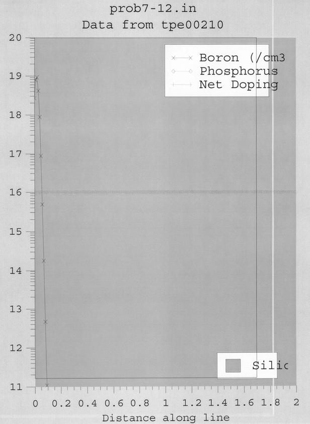
33 . The SUPREM input file for this problem is: TITLE Problem 7- COMMENT Initialize silicon substrate INITIALIZE <> Silicon Phosphor Concentratione4 COMMENT Implant Boron IMPLANT Boron Energy3 Dosee3 PRINT Layers Active Concentration Phosphorus Boron Net PLOT Active Net Cmine STOP End Problem 7- The resulting doping profile is shown in the figure below. Examining this figure and the SUPREM output file gives: (a) The peak of the implanted boron occurs at a depth of. µm. (b) The boron concentration at the peak is 8.59e7 cm -3. (c) The junction depth is.449 µm. 3
34 . The SUPREM input parameters that must be determined are the dose and implant energy. The dose can be determined from Eq. in Chapter 6 as Q( t).3c s Dt where C s can be read directly from the SUPREM output file for Example 3 in Chapter 6 as 4.6e9 cm -3, D.3e 6 cm /s for boron at 85 o C (see Figure 6.4), and t 9 s. Substituting these numbers into the above expression gives a dose of.36e3 cm -. The implant energy required can be approximated by matching the diffused and implanted concentration profiles at the surface (x ) and at the junction and using Eq. to solve for R p and σ p simultaneously. Note from the SUPREM output file corresponding to Example 3 in Chapter 6 that the junction occurs at x j.555 µm, at which point the doping concentration is 6 cm -3. As stated before, the surface concentration is 4.6e9 cm -3. These equations cannot be solved analytically, but after several iterations, the approximate values of R p and σ p required are found to be. µm and.8 µm, respectively. These values correspond to an implant energy of 5 kev (extrapolating from Figure 7.6a). The require SUPREM input file is therefore: TITLE Problem 7- COMMENT Initialize silicon substrate INITIALIZE <> Silicon Phosphor Concentratione6 COMMENT Implant Boron IMPLANT Boron Energy5 Dose.36e3 PRINT Layers Active Concentration Phosphorus Boron Net PLOT Active Net Cmine STOP End Problem 7- The resulting doping profile appears in the figure below. 3
35 3
36 CHAPTER 8. ν av vf f v v dv dv 8kT πm Where f ν 4 π M kt 3 / Mν ν exp kt M: Molecular mass k: Boltzmann constant.38-3 J/k T: The absolute temperature ν: Speed of molecular So that ν av π m/sec 4.68 cm/sec..66. λ cm P( in Pa) P 4.4 Pa. λ 5 3. For close-packing arrange, there are 3 pie shaped sections in the equilateral triangle. Each section corresponds to /6 of an atom. Therefore N s number of atoms contained in the triangle area of the triangle 3d 3( atoms/cm. ) d d 33
37 dd 4. (a) The pressure at 97 C (43K) is.9 - Pa for Ga and 3 Pa for As. The arrival rate is given by the product of the impringement rate and A/πL : Arrival rate.64 P MT A πl π.9 5 Ga molecules/cm s The growth rate is determined by the Ga arrival rate and is given by (.9 5 ).8/(6 4 ) 3.5 Å/s 8 Å/min. (b) The pressure at 7ºC for tin is.66-6 Pa. The molecular weight is Therefore the arrival rate is π.8 molecular/cm s If Sn atoms are fully incorporated and active in the Ga sublattice of GaAs, we have an electron concentration of cm The x value is about.5, which is obtained from Fig
38 6. The lattice constants for InAs, GaAs, Si and Ge are 6.5, 5.65,5.43, and 5.65 Å, respectively. Therefore, the f value for InAs-GaAs system is f ( ) And for Ge-Si system is f ( ) (a) For SiN x H y Si. N x x.83 y atomic % H y y.46 The empirical formula is SiN.83 H.46. (b) ρ 5 8 e Ω-cm As the Si/N ratio increases, the resistivity decreases exponentially. 8. Set Ta O 5 thickness 3t, ε 5 then SiO thickness t, ε 3.9 Si 3 N 4 thickness t, ε 3 7.6, area A εε A 3t CTa O5 C C ONO ONO t ε ε t t + + ε ε A ε ε A A 3 ε ε 3ε A ( ε + ε )t CTa O ε 5 CONO 3ε ε 3 3 ( ε + ε ) 5( )
39 9. Set BST thickness 3t, ε 5, area A SiO thickness t, ε 3.9, area A Si 3 N 4 thickness t, ε 3 7.6, area A then ε ε A ε ε 3ε A 3t ( ε + ε )t A A Let Ta O 5 thickness 3t, ε 5 SiO thickness t, ε 3.9 Si 3 N 4 thickness t, ε area A then εε A ε ε A 3t d 3ε t d.468t. ε 36
40 . The deposition rate can be expressed as r r exp (-E a /kt) where E a.6 ev for silane-oxygen reaction. Therefore for T 698 K r( T ) exp.6 r( T ) kt kt ln T 4 T 3 K We can use energy-enhanced CVD methods such as using a focused energy source or UV lamp. Another method is to use boron doped P-glass which will reflow at temperatures less than Moderately low temperatures are usually used for polysilicon deposition, and silane decomposition occurs at lower temperatures than that for chloride reactions. In addition, silane is used for better coverage over amorphous materials such SiO. 4. There are two reasons. One is to minimize the thermal budget of the wafer, reducing dopant diffusion and material degradation. In addition, fewer gas phase reactions occur at lower temperatures, resulting in smoother and better adhering films. Another reason is that the polysilicon will have small grains. The finer grains are easier to mask and etch to give smooth and uniform edges. However, for temperatures less than 575 ºC the deposition rate is too low. 5. The flat-band voltage shift is V FB.5 V ~ ε ox Number of fixed oxide charge is Q ot C C F/cm d 5. 37
41 .5C q To remove these charges, a 45 heat treatment in hydrogen for about 3 minutes is required. cm - 6. /.5 8 sqs. Therefore, the resistance of the metal line is Ω. 7. For TiSi nm For CoSi nm. 8. For TiSi : Advantage: low resistivity It can reduce native-oxide layers TiSi on the gate electrode is more resistant to high-field-induced hot-electron degradation. Disadvantage: bridging effect occurs. Larger Si consumption during formation of TiSi Less thermal stability For CoSi : Advantage: low resistivity High temperature stability No bridging effect A selective chemical etch exits Low shear forces Disadvantage: not a good candidate for polycides 38
42 9. (a) L 6 R ρ.67 4 A Ω εa εtl C. 9 4 d S F RC ns (b) L 6 R ρ.7 4 A ε εtl C 4 d S RC..4 ns Ω. 4 A 3.4 (c) We can decrease the RC delay by 55%. Ratio F. (a) L 6 3 R ρ Ω 4 4 A εa εtl C 8.7 F 4 d S.36 RC ns.. (b) R ρ L A Ω 4 εa εtl C 4 d S.36 RC 3 RC ns 3.5 ns F. (a) The aluminum runner can be considered as two segments connected in series: % (or.4 mm) of the length is half thickness (.5 µm) and the remaining.6 mm is full thickness (µm). The total resistance is R ρ A (.5 A 3 4 ) 39
43 7 Ω. The limiting current I is given by the maximum allowed current density times cross-sectional area of the thinner conductor sections: I 5 5 A/cm ( ).5-3 A.5 ma. The voltage drop across the whole conductor is then..5 µm V RI 7Ω.5 3 A.8V..5 µm Cu Al 4 nm 6 nm h: height, W : width, t : thickness, assume that the resistivities of the cladding layer and TiN are much larger than R Al ρ R Cu ρ Al Cu h W When R Al R Cu.7 (.5 ρ A.).5 and ρ.7 h W (.5 t) (.5 t).7.7 Then.4.5 (.5 t) t.73 µm 73 nm. Cu 4
44 CHAPTER 9. Each U-shape section (refer to the figure) has an area of 5 µm 8 µm 4 µm. Therefore, there are (5) / U-shaped section. Each section contains long lines with 48 squares each, 4 corner squares, bottom square, and half squares at the top. Therefore the resistance for each section is kω / ( ) 5.6 kω The maximum resistance is then Ω 78 MΩ. The area required on the chip is 4
45 C d A ε ox 7 ( 3 )(5 ) cm µm µm Refer to Fig.9.4a and using negative photoresist of all levels (a) Ion implantation mask (for p + implantation and gate oxide) (b) Contact windows ( µm) (c) Metallization mask (using Al to form ohmic contact in the contact window and form the MOS capacitor). Because of the registration errors, an additional µm is incorporated in all critical dimensions. 4
46 3. If the space between lines is µm, then there is 4 µm for each turn (i.e., n, for one turn). Assume there are n turns, from Eq.6, L µ n r. -6 n r, where r can be replaced by n. Then, we can obtain that n is 3. 43
47 4. (a) Metal, (b) contact hole, (c) Metal. (a) Metal, (b) contact hole, (c) Metal. 44
48 5. The circuit diagram and device cross-section of a clamped transistor are shown in (a) and (b), respectively. 6. (a) The undoped polysilicon is used for isolation. (b) The polysilicon is used as a solid-phase diffusion source to form the extrinsic base region and the base electrode. (c) The polysilicon is used as a solid-phase diffusion source to form the emitter region and the emitter electrode. 7. (a) For 3 kev boron, R p nm and R p 34 nm. Assuming that R p and R p for 45
49 boron are the same in Si and SiO the peak concentration is given by S π R p 8 π (34 7 ) cm 3 The amount of boron ions in the silicon is Q q d S R erfc p d R p S π R erfc cm p exp ( x R ) p R p dx Assume that the implanted boron ions form a negative sheet charge near the Si-SiO interface, then 9 Q.6 (7.88 ) V T q / C ox.9 V 4 7 q /( 5 ) (b) For 8 kev arsenic implantation, R p 49 nm and R p 8 nm. The peak arsenic concentration is S π R p 6 π (8 7. ) cm 3. 46
50 8. (a) Because ()-oriented silicon has lower (~ one tenth) interface-trapped charge and a lower fixed oxide charge. (b) If the field oxide is too thin, it may not provide a large enough threshold voltage for adequate isolation between neighboring MOSFETs. (c) The typical sheet resistance of heavily doped polysilicon gate is to 3 Ω /, which is adequate for MOSFETs with gate lengths larger than 3 µm. For shorter gates, the sheet resistance of polysilicon is too high and will cause large RC 47
51 delays. We can use refractory metals (e.g., Mo) or silicides as the gate material to reduce the sheet resistance to about Ω /. (d) A self-aligned gate can be obtained by first defining the MOS gate structure, then using the gate electrode as a mask for the source/drain implantation. The self-aligned gate can minimize parasitic capacitance caused by the source/drain regions extending underneath the gate electrode (due to diffusion or misalignment). (e) P-glass can be used for insulation between conducting layers, for diffusion and ion implantation masks, and for passivation to protect devices from impurities, moisture, and scratches. 9. The lower insulator has a dielectric constant ε /ε 4 and a thickness d nm The upper insulator has a dielectric constant ε /ε and a thickness d nm. Upon application of a positive voltage V G to the external gate, electric field E and E are established in the d and d respectively. We have, from Gauss law, that ε E ε E +Q and V G E d + E d where Q is the stored charge on the floating gate. From these above two equations, we obtain E d + d V G ( ε / ε ) ε + ε ( / d ) + Q d 48
52 J 7 7 Q σ E Q (a) If the stored charge does not reduce E by a significant amount (i.e.,. >>.6 5 Q, Q we can write 6 (.5 ) t 8 σedt'. t. 5 8 Q 5 V T.565 V C 4 7 ( 8.85 )/( ) 5 (b) when t, J we have Q. / C. C Then 7 Q 8.84 V T 9.98 V. 5 C / 4 ( 8.85 ). 49
53 5
54 . The oxide capacitance per unit area is given by C ox ε d SiO F/cm and the maximum current supplied by the device is I DS W 5µ m 7 µ Cox ( VG VT ) 3.5 ( VG VT ) 5 ma L.5µ m 5
55 and the maximum allowable wire resistance is. V/5 ma, or Ω. Then, the length of the wire must be 8 R Area Ω cm L.74 cm 8 ρ.7 Ω cm or 74 µm. This is a long distance compared to most device spacing. When driving signals between widely spaced logic blocks however, minimum feature sized lines would not be appropriate.. 5
56 3. To solve the short-channel effect of devices. 4. The device performance will be degraded from the boron penetration. There are 53
57 methods to reduce this effect: () using rapid thermal annealing to reduce the time at high temperatures, consequently reduces the diffusion of boron, () using nitrided oxide to suppress the boron penetration, since boron can easily combine with nitrogen and becomes less mobile, (3) making a multi-layer of polysilicon to trap the boron atoms at the interface of each layer. 5. Total capacitance of the stacked gate structure is : ε C d ε d ε d ε + d d d nm. 6. Disadvantages of LOCOS: () high temperature and long oxidation time cause V T shift, () bird s beak, (3) not a planar surface, (4) exhibits oxide thinning effect. Advantages of shallow trench isolation: () planar surface, () no high temperature processing and long oxidation time, (3) no oxide thinning effect, (4) no bird s beak. 7. For isolation between the metal and the substrate. 8. GaAs lacks of high-quality insulating film. 9. Answers will vary. If we ignore the contributions of isolation region processing, the structure can be simulated using four SUPREM input decks. The first deck simulates 54
58 processing in the active region of the device, up to the point of the isolation oxidation. The second deck starts with the results from the first deck and completes all processing in the active regions. This allows the doping profile through the emitter to be plotted (for part b). The third deck is similar to the second, except it eliminates the emitter implant and facilitates plotting of the doping profile through the base region (for part a). The final deck is also similar to the second, except that it eliminates the base implant and facilitates plotting the doping profile through the collector region (for part c). The complete process sequence is as follows: ) Begin with a high-resistivity, <>, p-type silicon substrate. ) Grow a µm SiO layer. 3) Remove the oxide in the areas where the buried layers are to be placed. 4) Implant antimony at a dose of e5 cm -. Drive in the buried layer for 5 hours at 5 o C. 5) Etch the silicon dioxide from the surface. 6) Grow a.6 µm arsenic-doped epitaxial layer. 7) Grow a 4 Å pad oxide. 8) Deposit 8 Å of silicon nitride. 9) Etch the oxide and nitride from the isolation regions. ) Etch the silicon halfway through the epi-layer. 55
59 ) Implant boron in the field regions with a dose of e3 cm - at an energy of 5 kev. ) Oxidize the field regions to a thickness approximately one-half that of the epi-layer. 3) Implant the base region with boron at a dose of e4 cm - at an energy of 5 kev. 4) Etch the oxide from the emitter region. 5) Implant emitter collector contact regions with arsenic at a dose of 5e5 cm - at an energy of kev. 6) Drive-in the arsenic and activate the base diffusion. The SUPREM input decks are as follows: TITLE BJT Deck COMMENT Initial Active Region Processing COMMENT Initialize silicon substrate INITIALIZE <> Silicon Boron Concentration5e4 COMMENT Grow masking oxide for non-active regions DIFFUSION Time Temperature5 WetO COMMENT Etch oxide over buried layer regions ETCH Oxide COMMENT Implant and drive-in antimony buried layer IMPLANT Antimony Dose5e4 Energy DIFFUSION Time5 Temperature5 DryO DIFFUSION Time3 Temperature5 COMMENT Etch the oxide ETCH Oxide COMMENT Grow.6 µm of arsenic-doped epi EPITAXY Temperature5 Time4 Growth.Rate.4 Arsenic Gas.Conc5e5 56
60 COMMENT Grow 4 A pad oxide DIFFUSION Time Temperature6 DryO COMMENT Deposit nitride to mask the field oxidation DEPOSITION Nitride Thickness.8 SAVEFILE Structur Filenamebjtactiveinit.str STOP End BJT TITLE BJT Deck COMMENT Final Active Region Processing for Emitter Profile COMMENT Start with previous results INITIALIZE Structurbjtactiveinit.str COMMENT Field oxide growth DIFFUSION Time3 Temperature8 t.rate DIFFUSION Time5 Temperature DryO DIFFUSION Time Temperature Wet DIFFUSION Time5 Temperature DryO DIFFUSION Time Temperature t.rate-3 COMMENT Etch the oxide and nitride layers ETCH Oxide ETCH Nitride ETCH Oxide COMMENT Implant boron base IMPLANT Boron Dosee4 Energy5 COMMENT Remove oxide from emitter region ETCH Oxide COMMENT Implant arsenic emitter and collector contacts IMPLANT Arsenic Dose5e5 Energy COMMENT Drive-in emitter and collector contact regions DIFFUSION Time Temperature PRINT Layers PLOT Chemical Boron Arsenic Phosphor Net STOP End BJT TITLE BJT Deck 3 COMMENT Active Region Processing for Base Profile COMMENT Start with previous results 57
61 INITIALIZE Structurbjtactiveinit.str COMMENT Field oxide growth DIFFUSION Time3 Temperature8 t.rate DIFFUSION Time5 Temperature DryO DIFFUSION Time Temperature Wet DIFFUSION Time5 Temperature DryO DIFFUSION Time Temperature t.rate-3 COMMENT Etch the oxide and nitride layers ETCH Oxide ETCH Nitride ETCH Oxide COMMENT Implant boron base IMPLANT Boron Dosee4 Energy5 COMMENT Remove oxide from emitter region ETCH Oxide COMMENT Drive-in emitter and collector contact region DIFFUSION Time Temperature PRINT Layers PLOT Chemical Boron Arsenic Phosphor Net STOP End BJT 3 TITLE BJT Deck 4 COMMENT Active Region Processing for Collector Profile COMMENT Start with previous results INITIALIZE Structurbjtactiveinit.str COMMENT Field oxide growth DIFFUSION Time3 Temperature8 t.rate DIFFUSION Time5 Temperature DryO DIFFUSION Time Temperature Wet DIFFUSION Time5 Temperature DryO DIFFUSION Time Temperature t.rate-3 COMMENT Etch the oxide and nitride layers ETCH Oxide ETCH Nitride ETCH Oxide COMMENT Remove oxide from emitter region ETCH Oxide 58
62 COMMENT Implant arsenic emitter and collector contacts IMPLANT Arsenic Dose5e5 Energy COMMENT Drive-in emitter and collector contact regions DIFFUSION Time Temperature PRINT Layers PLOT Chemical Boron Arsenic Phosphor Net STOP End BJT 4 The resulting doping profiles though the base, emitter, and collector (parts a, b, and c), respectively, are shown in the following three figures: (a) 59
63 (b) 6
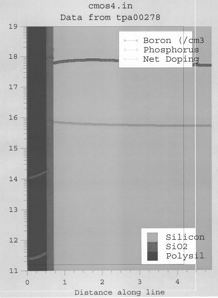
64 (c). Answers will vary. For the sake of simplicity, we will ignore isolation-related processing. The structure can be simulated using four SUPREM input decks (one for each requested profile). The complete process sequence is as follows: 6
65 ) Start with a <>, n-type silicon substrate. ) Grow a.9 µm SiO layer. 3) Remove the oxide in the p-well areas. 4) Implant boron well at a dose of 5e4 cm - at 5 kev. 5) Drive in the p-well for 6 hours at 5 o C. 6) Remove oxide in PMOS source/drain regions. 7) Implant boron for PMOS source/drain at a dose of e4 cm - at kev. 8) Drive in the PMOS source/drain regions for.5 hours at o C. 9) Etch oxide in NMOS source/drain regions. ) Implant phosphorus for NMOS source/drain at a dose of e4 cm - at kev. ) Drive in the NMOS source/drain regions for.5 hours at o C. ) Etch oxide in gate areas. 3) Grow 5 Å gate oxide. 4) Deposit and pattern polysilicon gates. 5) Grow passivation oxide. 6) Deposit and pattern metallization. The SUPREM input decks are and corresponding outputs as follows: TITLE CMOS Deck COMMENT PMOS source/drain COMMENT Initialize silicon substrate INITIALIZE <> Silicon Phosphorus Concentration5e5 Thickness5 6
66 COMMENT Grow field oxide DIFFUSION Time Temperature WetO COMMENT Etch oxide after p-well implant ETCH Oxide COMMENT P-well drive-in DIFFUSION Time9 Temperature5 DryO COMMENT Etch the oxide prior to PMOS source/drain implant ETCH Oxide COMMENT PMOS source/drain implant IMPLANT Boron Dosee4 Energy COMMENT PMOS source/drain drive-in DIFFUSION Time5 Temperature DryO COMMENT NMOS source/drain drive-in and gate oxidation DIFFUSION Time5 Temperature DryO COMMENT Etch oxide ETCH Oxide COMMENT Deposit metal DEPOSITION Aluminum Thickness. PRINT Layers PLOT Chemical Boron Phosphor Net STOP End CMOS 63

67 (a) TITLE CMOS Deck COMMENT PMOS Gate COMMENT Initialize silicon substrate INITIALIZE <> Silicon Phosphorus Concentration5e5 Thickness5 COMMENT Grow field oxide DIFFUSION Time Temperature WetO COMMENT Etch oxide after p-well implant ETCH Oxide COMMENT P-well drive-in DIFFUSION Time9 Temperature5 DryO 64
68 COMMENT Etch the oxide prior to PMOS source/drain implant ETCH Oxide COMMENT PMOS source/drain drive-in DIFFUSION Time5 Temperature DryO COMMENT NMOS source/drain drive-in and gate oxidation DIFFUSION Time5 Temperature DryO COMMENT Deposit polysilicon DEPOSITION Polysilicon Thickness.5 COMMENT Grow passivation oxide DIFFUSION Time3 Temperature DryO PRINT Layers PLOT Chemical Boron Phosphor Net STOP End CMOS 65
69 (b) TITLE CMOS Deck 3 COMMENT NMOS source/drain COMMENT Initialize silicon substrate INITIALIZE <> Silicon Phosphorus Concentration5e5 Thickness5 COMMENT Grow field oxide DIFFUSION Time Temperature WetO COMMENT Etch oxide in p-well region ETCH Oxide COMMENT P-well implant 66
70 IMPLANT Boron Dose5e4 Energy5 COMMENT P-well drive-in DIFFUSION Time9 Temperature5 DryO COMMENT PMOS source/drain drive-in DIFFUSION Time5 Temperature DryO COMMENT Etch the oxide prior to NMOS source/drain implant ETCH Oxide COMMENT NMOS source/drain implant IMPLANT Phosphorus Dosee4 Energy COMMENT NMOS source/drain drive-in and gate oxidation DIFFUSION Time5 Temperature DryO COMMENT Etch oxide ETCH Oxide COMMENT Deposit metal DEPOSITION Aluminum Thickness. PRINT Layers PLOT Chemical Boron Phosphor Net STOP End CMOS 3 67
71 (c) TITLE CMOS Deck 4 COMMENT NMOS gate COMMENT Initialize silicon substrate INITIALIZE <> Silicon Phosphorus Concentration5e5 Thickness5 COMMENT Grow field oxide DIFFUSION Time Temperature WetO COMMENT Etch oxide in p-well region ETCH Oxide 68
72 COMMENT P-well implant IMPLANT Boron Dose5e4 Energy5 COMMENT P-well drive-in DIFFUSION Time9 Temperature5 DryO COMMENT PMOS source/drain drive-in DIFFUSION Time5 Temperature DryO COMMENT Etch the oxide prior to NMOS source/drain implant ETCH Oxide COMMENT NMOS source/drain drive-in and gate oxidation DIFFUSION Time5 Temperature DryO COMMENT Deposit polysilicon DEPOSITION Polysilicon Thickness.5 COMMENT Grow passivation oxide DIFFUSION Time3 Temperature DryO PRINT Layers PLOT Chemical Boron Phosphor Net STOP End CMOS 4 69
73 7 (d)
74 CHAPTER. x -chart: Center µ.75 V 3σ 3(.) UCL µ V n 3σ LCL V n s-chart: Center s c 4 σ.977(.).973 V 4 ) UCL s + 3σ c (.)( V LCL s - 3σ c 4.8 V. x -chart: Center x.734 V 3s UCL x V c n 4 LCL 3s x c n 4.6 V s-chart: Center s.5 V s UCL s + 3 c4.5 V c s LCL s 3 c c V 3. Let ED exposure dose, DT develop time, BT bake temperature ED DT BT Y () () (3) Div. Eff. ID Avg. 7
75 ED DT ED x DT BT ED x BT DT x BT ED x DT x BT 4. Let: days blocks (i.e., n 3) processes treatments (i.e., k 5) Then we have: A B C D E y i Day Day Day y y 53.6 t ANOVA Table: Source Sum of Squares Degrees of Freedom Mean Square Average (S A ) 3,84,94.4 3,84,94.4 Blocks (S B ) 4,75,375 ( ) Treatments (S T ), ( ) Residual (S R ) ( s R ) s B s T where: S A nky 3,84,94.4 n i ( S k y y), DF n B k t ( i S n y y), DF k T k n R t i ( t S y y y + y), DF (n )(k ) ti i t Now: s B s 9.48 / R 7
76 s T / sr 6.55 A. Significance level for the null hypothesis that the blocks are the same is very low, since P( F 9.48) ~,8 > B. The same is true for the hypothesis that the treatments are the same, since: P (, 8 F 4 > 6.55) ~ I. The processes are significantly different. II. The processing dates have significant differences. 5. From Eq. 33: Y exp(-a c D ) N exp(-na c D ) where: Y.95 N, A c WL (e-4 cm)(e-4 cm) e-7 cm > lny D 5.3 cm - NA c 6. Murphy s Yield Integral (Eq. 34): Y e A D c f ( D ) dd Uniform defect distribution: f ( D) / D for D D Y D e Ac D dd D D e A Ac D c D > Y uniform D D Ac e A c Triangular defect distribution: f ( D) D / D for D D D + for D D D D D 73
77 Y D D A D D c e dd + e D D A D c D D + dd D Y D e A AD c c D ( A D ) ( A D ) c D e A A D c c D D + D c e A A D c D D > Y triangular D e D Ac A c Exponential Defect Distribution: f ( D) D D exp D Y A / D( e c D D D e dd exp D D D + A cd ) dd + Ac D D( + Ac D exp D ) > Y exp onential + D A c 7. Use Murphy s Yield Integral (Eq. 34): Y AD e f ( D) dd, where: A cm, f(d) -D+ Y. e.5 D ( D + )dd -..5 De D dd +. D.5 e dd. e D 4.5 D e ( AD )..5 > Y.94 % 74
78 CHAPTER. (a) L RC ρ ε A ox A d ( 69.3 ).38 s.38 ns. (b) For a polysilicon runner RC R 3 7 ns square 4 L ε ox W A d 4 ( 69.3 ) s 4 4 ( ).5 Therefore the polysilicon runner s RC time constant is 5 times larger than the aluminum runner. 4. When we combine the logic circuits and memory on the chip, we need multiple supply voltages. For reliability issue, different oxide thicknesses are needed for different supply voltages. 3. (a) C total C Ta O + C 5 nitride hence EOT Å (b) EOT 6.7 Å. 75
Microelettronica. Planar Technology for Silicon Integrated Circuits Fabrication. 26/02/2017 A. Neviani - Microelettronica
 Microelettronica Planar Technology for Silicon Integrated Circuits Fabrication 26/02/2017 A. Neviani - Microelettronica Introduction Simplified crosssection of an nmosfet and a pmosfet Simplified crosssection
HOMEWORK 4 and 5. March 15, Homework is due on Monday March 30, 2009 in Class. Answer the following questions from the Course Textbook:
 HOMEWORK 4 and 5 March 15, 2009 Homework is due on Monday March 30, 2009 in Class. Chapter 7 Answer the following questions from the Course Textbook: 7.2, 7.3, 7.4, 7.5, 7.6*, 7.7, 7.9*, 7.10*, 7.16, 7.17*,
EE 330 Lecture 9. IC Fabrication Technology Part 2
 EE 330 Lecture 9 IC Fabrication Technology Part 2 Quiz 8 A 2m silicon crystal is cut into wafers using a wire saw. If the wire diameter is 220um and the wafer thickness is 350um, how many wafers will this
Doping and Oxidation
 Technische Universität Graz Institute of Solid State Physics Doping and Oxidation Franssila: Chapters 13,14, 15 Peter Hadley Technische Universität Graz Institute of Solid State Physics Doping Add donors
EE 330 Lecture 9. IC Fabrication Technology Part II. -Oxidation -Epitaxy -Polysilicon -Planarization -Resistance and Capacitance in Interconnects
 EE 330 Lecture 9 IC Fabrication Technology Part II -Oxidation -Epitaxy -Polysilicon -Planarization -Resistance and Capacitance in Interconnects Review from Last Time IC Fabrication Technology Crystal Preparation
Czochralski Crystal Growth
 Czochralski Crystal Growth Crystal Pulling Crystal Ingots Shaping and Polishing 300 mm wafer 1 2 Advantage of larger diameter wafers Wafer area larger Chip area larger 3 4 Large-Diameter Wafer Handling
EE THERMAL OXIDATION - Chapter 6. Basic Concepts
 EE 22 FALL 999-00 THERMAL OXIDATION - Chapter 6 Basic Concepts SiO 2 and the Si/SiO 2 interface are the principal reasons for silicon s dominance in the IC industry. SiO 2 : Easily selectively etched using
VLSI Digital Systems Design
 VLSI Digital Systems Design CMOS Processing cmpe222_03process_ppt.ppt 1 Si Purification Chemical purification of Si Zone refined Induction furnace Si ingot melted in localized zone Molten zone moved from
Microstructure of Electronic Materials. Amorphous materials. Single-Crystal Material. Professor N Cheung, U.C. Berkeley
 Microstructure of Electronic Materials Amorphous materials Single-Crystal Material 1 The Si Atom The Si Crystal diamond structure High-performance semiconductor devices require defect-free crystals 2 Crystallographic
Chapter 3 CMOS processing technology
 Chapter 3 CMOS processing technology (How to make a CMOS?) Si + impurity acceptors(p-type) donors (n-type) p-type + n-type => pn junction (I-V) 3.1.1 (Wafer) Wafer = A disk of silicon (0.25 mm - 1 mm thick),
Problem 1 Lab Questions ( 20 points total)
") Problem 1 Lab Questions ( 20 points total) (a) (3 points ) In our EE143 lab, we use Phosphorus for the source and drain diffusion. However, most advanced processes use Arsenic. What is the advantage of
Problem 1 Lab Questions ( 20 points total) (a) (3 points ) In our EE143 lab, we use Phosphorus for the source and drain diffusion. However, most advanced processes use Arsenic. What is the advantage of
CHAPTER 4: Oxidation. Chapter 4 1. Oxidation of silicon is an important process in VLSI. The typical roles of SiO 2 are:
 Chapter 4 1 CHAPTER 4: Oxidation Oxidation of silicon is an important process in VLSI. The typical roles of SiO 2 are: 1. mask against implant or diffusion of dopant into silicon 2. surface passivation
Figure 2.3 (cont., p. 60) (e) Block diagram of Pentium 4 processor with 42 million transistors (2000). [Courtesy Intel Corporation.
 (e) Block diagram of Pentium 4 processor with 42 million transistors (2000). [Courtesy Intel Corporation.") Figure 2.1 (p. 58) Basic fabrication steps in the silicon planar process: (a) oxide formation, (b) selective oxide removal, (c) deposition of dopant atoms on wafer, (d) diffusion of dopant atoms into exposed
Figure 2.1 (p. 58) Basic fabrication steps in the silicon planar process: (a) oxide formation, (b) selective oxide removal, (c) deposition of dopant atoms on wafer, (d) diffusion of dopant atoms into exposed
EE 330 Lecture 8. IC Fabrication Technology Part II. - Oxidation - Epitaxy - Polysilicon - Interconnects
 EE 330 Lecture 8 IC Fabrication Technology Part II - Oxidation - Epitaxy - Polysilicon - Interconnects Review from Last Time MOS Transistor Bulk Source Gate Drain p-channel MOSFET Lightly-doped n-type
EECS130 Integrated Circuit Devices
 EECS130 Integrated Circuit Devices Professor Ali Javey 9/13/2007 Fabrication Technology Lecture 1 Silicon Device Fabrication Technology Over 10 15 transistors (or 100,000 for every person in the world)
EE 434 Lecture 9. IC Fabrication Technology
 EE 434 Lecture 9 IC Fabrication Technology Quiz 7 The layout of a film resistor with electrodes A and B is shown. If the sheet resistance of the film is 40 /, determine the resistance between nodes A and
Section 4: Thermal Oxidation. Jaeger Chapter 3. EE143 - Ali Javey
 Section 4: Thermal Oxidation Jaeger Chapter 3 Properties of O Thermal O is amorphous. Weight Density =.0 gm/cm 3 Molecular Density =.3E molecules/cm 3 O Crystalline O [Quartz] =.65 gm/cm 3 (1) Excellent
PROCESS FLOW AN INSIGHT INTO CMOS FABRICATION PROCESS
 Contents: VI Sem ECE 06EC63: Analog and Mixed Mode VLSI Design PROCESS FLOW AN INSIGHT INTO CMOS FABRICATION PROCESS 1. Introduction 2. CMOS Fabrication 3. Simplified View of Fabrication Process 3.1 Alternative
Fabrication and Layout
 ECEN454 Digital Integrated Circuit Design Fabrication and Layout ECEN 454 3.1 A Glimpse at MOS Device Polysilicon Aluminum ECEN 475 4.2 1 Material Classification Insulators Glass, diamond, silicon oxide
VLSI INTRODUCTION P.VIDYA SAGAR ( ASSOCIATE PROFESSOR) Department of Electronics and Communication Engineering, VBIT
 Department of Electronics and Communication Engineering, VBIT") VLSI INTRODUCTION P.VIDYA SAGAR ( ASSOCIATE PROFESSOR) contents UNIT I INTRODUCTION: Introduction to IC Technology MOS, PMOS, NMOS, CMOS & BiCMOS technologies. BASIC ELECTRICAL PROPERTIES : Basic Electrical
VLSI INTRODUCTION P.VIDYA SAGAR ( ASSOCIATE PROFESSOR) contents UNIT I INTRODUCTION: Introduction to IC Technology MOS, PMOS, NMOS, CMOS & BiCMOS technologies. BASIC ELECTRICAL PROPERTIES : Basic Electrical
Fabrication Technology
 Fabrication Technology By B.G.Balagangadhar Department of Electronics and Communication Ghousia College of Engineering, Ramanagaram 1 OUTLINE Introduction Why Silicon The purity of Silicon Czochralski
Chapter 3 Silicon Device Fabrication Technology
 Chapter 3 Silicon Device Fabrication Technology Over 10 15 transistors (or 100,000 for every person in the world) are manufactured every year. VLSI (Very Large Scale Integration) ULSI (Ultra Large Scale
Process Integration. MEMS Release Techniques Sacrificial Layer Removal Substrate Undercut
 Process Integration Self-aligned Techniques LOCOS- self-aligned channel stop Self-aligned Source/Drain Lightly Doped Drain (LDD) Self-aligned silicide (SALICIDE) Self-aligned oxide gap MEMS Release Techniques
Isolation Technology. Dr. Lynn Fuller
 ROCHESTER INSTITUTE OF TECHNOLOGY MICROELECTRONIC ENGINEERING Isolation Technology Dr. Lynn Fuller Motorola Professor 82 Lomb Memorial Drive Rochester, NY 14623-5604 Tel (585) 475-2035 Fax (585) 475-5041
MOSFET. n+ poly Si. p- substrate
 EE143 Midterm #1 Solutions Fall 2005 (maximum score is 97) Problem 1 Processing Modules and Simple Process Sequence (25 points total) The following schematic cross-section shows a MOSFET together with
MOS Front-End. Field effect transistor
 MOS Front-End Back-end Transistor Contact Front-end p-well STI n-well Front-end-of-line includes substrate, isolation, wells, transistor, silicide Field effect transistor MOSFET: Metal-Oxide-Semiconductor
Process Integration. NMOS Generic NMOS Process Flow. CMOS - The MOSIS Process Flow
 Process Integration Self-aligned Techniques LOCOS- self-aligned channel stop Self-aligned Source/Drain Lightly Doped Drain (LDD) Self-aligned silicide (SALICIDE) Self-aligned oxide gap MEMS Release Techniques
Ajay Kumar Gautam [VLSI TECHNOLOGY] VLSI Technology for 3RD Year ECE/EEE Uttarakhand Technical University
![Ajay Kumar Gautam [VLSI TECHNOLOGY] VLSI Technology for 3RD Year ECE/EEE Uttarakhand Technical University](/thumbs/75/72824557.jpg "Ajay Kumar Gautam [VLSI TECHNOLOGY] VLSI Technology for 3RD Year ECE/EEE Uttarakhand Technical University") 2014 Ajay Kumar Gautam [VLSI TECHNOLOGY] VLSI Technology for 3RD Year ECE/EEE Uttarakhand Technical University Page1 Syllabus UNIT 1 Introduction to VLSI Technology: Classification of ICs, Scale of integration,
2014 Ajay Kumar Gautam [VLSI TECHNOLOGY] VLSI Technology for 3RD Year ECE/EEE Uttarakhand Technical University Page1 Syllabus UNIT 1 Introduction to VLSI Technology: Classification of ICs, Scale of integration,
Microfabrication of Integrated Circuits
 Microfabrication of Integrated Circuits OUTLINE History Basic Processes Implant; Oxidation; Photolithography; Masks Layout and Process Flow Device Cross Section Evolution Lecture 38, 12/05/05 Reading This
Lecture 030 Integrated Circuit Technology - I (5/8/03) Page 030-1
 Page 030-1") Lecture 030 Integrated Circuit Technology - I (5/8/03) Page 030-1 LECTURE 030 INTEGRATED CIRCUIT TECHNOLOGY - I (References [7,8]) Objective The objective of this presentation is: 1.) Illustrate integrated
Lecture 030 Integrated Circuit Technology - I (5/8/03) Page 030-1 LECTURE 030 INTEGRATED CIRCUIT TECHNOLOGY - I (References [7,8]) Objective The objective of this presentation is: 1.) Illustrate integrated
EE 5344 Introduction to MEMS. CHAPTER 3 Conventional Si Processing
 3. Conventional licon Processing Micromachining, Microfabrication. EE 5344 Introduction to MEMS CHAPTER 3 Conventional Processing Why silicon? Abundant, cheap, easy to process. licon planar Integrated
CHAPTER - 4 CMOS PROCESSING TECHNOLOGY
 CHAPTER - 4 CMOS PROCESSING TECHNOLOGY Samir kamal Spring 2018 4.1 CHAPTER OBJECTIVES 1. Introduce the CMOS designer to the technology that is responsible for the semiconductor devices that might be designed
THERMAL OXIDATION - Chapter 6 Basic Concepts
 THERMAL OXIDATION - Chapter 6 Basic Concepts SiO 2 and the Si/SiO 2 interface are the principal reasons for silicon s dominance in the IC industry. Oxide Thickness µm 0. µm 0 nm nm Thermally Grown Oxides
3.155J / 6.152J Micro/Nano Processing Technology TAKE-HOME QUIZ FALL TERM 2005
 3.155J / 6.152J Micro/Nano Processing Technology TAKE-HOME QUIZ FALL TERM 2005 1) This is an open book, take-home quiz. You are not to consult with other class members or anyone else. You may discuss the
Microelectronics Devices
 Microelectronics Devices Yao-Joe Yang 1 Outline Basic semiconductor physics Semiconductor devices Resistors Capacitors P-N diodes BJT/MOSFET 2 Type of Solid Materials Solid materials may be classified
EE 560 FABRICATION OF MOS CIRCUITS. Kenneth R. Laker, University of Pennsylvania
 1 EE 560 FABRICATION OF MOS CIRCUITS 2 CMOS CHIP MANUFACTRING STEPS Substrate Wafer Wafer Fabrication (diffusion, oxidation, photomasking, ion implantation, thin film deposition, etc.) Finished Wafer Wafer
Lecture 19 Microfabrication 4/1/03 Prof. Andy Neureuther
 EECS 40 Spring 2003 Lecture 19 Microfabrication 4/1/03 Prof. ndy Neureuther How are Integrated Circuits made? Silicon wafers Oxide formation by growth or deposition Other films Pattern transfer by lithography
EE 330 Lecture 9. IC Fabrication Technology Part II. -Oxidation -Epitaxy -Polysilicon -Planarization -Resistance and Capacitance in Interconnects
 EE 330 Lecture 9 IC Fabrication Technology Part II -Oxidation -Epitaxy -Polysilicon -Planarization -Resistance and Capacitance in Interconnects Review from Last Time Etching Dry etch (anisotropic) SiO
Ion Implantation Most modern devices doped using ion implanters Ionize gas sources (single +, 2+ or 3+ ionization) Accelerate dopant ions to very
 Accelerate dopant ions to very") Ion Implantation Most modern devices doped using ion implanters Ionize gas sources (single +, 2+ or 3+ ionization) Accelerate dopant ions to very high voltages (10-600 KeV) Use analyzer to selection charge/mass
Ion Implantation Most modern devices doped using ion implanters Ionize gas sources (single +, 2+ or 3+ ionization) Accelerate dopant ions to very high voltages (10-600 KeV) Use analyzer to selection charge/mass
Chapter 4. UEEP2613 Microelectronic Fabrication. Oxidation
 Chapter 4 UEEP2613 Microelectronic Fabrication Oxidation Prepared by Dr. Lim Soo King 24 Jun 2012 Chapter 4...113 Oxidation...113 4.0 Introduction... 113 4.1 Chemistry of Silicon Dioxide Formation... 115
Complexity of IC Metallization. Early 21 st Century IC Technology
 EECS 42 Introduction to Digital Electronics Lecture # 25 Microfabrication Handout of This Lecture. Today: how are Integrated Circuits made? Silicon wafers Oxide formation by growth or deposition Other
CMOS Technology. Flow varies with process types & company. Start with substrate selection. N-Well CMOS Twin-Well CMOS STI
 CMOS Technology Flow varies with process types & company N-Well CMOS Twin-Well CMOS STI Start with substrate selection Type: n or p Doping level, resistivity Orientation, 100, or 101, etc Other parameters
Chapter 2 Manufacturing Process
 Digital Integrated Circuits A Design Perspective Chapter 2 Manufacturing Process 1 CMOS Process 2 CMOS Process (n-well) Both NMOS and PMOS must be built in the same silicon material. PMOS in n-well NMOS
EE40 Lec 22. IC Fabrication Technology. Prof. Nathan Cheung 11/19/2009
 Suggested Reading EE40 Lec 22 IC Fabrication Technology Prof. Nathan Cheung 11/19/2009 300mm Fab Tour http://www-03.ibm.com/technology/manufacturing/technology_tour_300mm_foundry.html Overview of IC Technology
CHAPTER 8: Diffusion. Chapter 8
 1 CHAPTER 8: Diffusion Diffusion and ion implantation are the two key processes to introduce a controlled amount of dopants into semiconductors and to alter the conductivity type. Figure 8.1 compares these
Section 4: Thermal Oxidation. Jaeger Chapter 3
 Section 4: Thermal Oxidation Jaeger Chapter 3 Properties of O Thermal O is amorphous. Weight Density =.0 gm/cm 3 Molecular Density =.3E molecules/cm 3 O Crystalline O [Quartz] =.65 gm/cm 3 (1) Excellent
Silicon Epitaxial CVD Want to create very sharp PN boundary grow one type layer on other in single crystal form High dopant layers on low dopant
 Silicon Epitaxial CVD Want to create very sharp PN boundary grow one type layer on other in single crystal form High dopant layers on low dopant substrate Creates latch up protection for CMOS Buried Epi
VLSI Technology Dr. Nandita Dasgupta Department of Electrical Engineering Indian Institute of Technology, Madras
 VLSI Technology Dr. Nandita Dasgupta Department of Electrical Engineering Indian Institute of Technology, Madras Lecture - 32 IC BJT - From junction isolation to LOCOS So, by now, we have completed all
ELEC 7364 Lecture Notes Summer Si Oxidation. by STELLA W. PANG. from The University of Michigan, Ann Arbor, MI, USA
 ELEC 7364 Lecture Notes Summer 2008 Si Oxidation by STELLA W. PANG from The University of Michigan, Ann Arbor, MI, USA Visiting Professor at The University of Hong Kong The University of Michigan Visiting
MICROCHIP MANUFACTURING by S. Wolf
 MICROCHIP MANUFACTURING by S. Wolf Chapter 13: THERMAL- OXIDATION of SILICON 2004 by LATTICE PRESS Chapter 13: THERMAL-OXIDATION of SILICON n CHAPTER CONTENTS Applications of Thermal Silicon-Dioxide Physical
Department of Electrical Engineering. Jungli, Taiwan
 Chapter 3 Fabrication of CMOS Integrated Circuits Jin-Fu Li Department of Electrical Engineering National Central University Jungli, Taiwan Background Outline The CMOS Process Flow Design Rules Latchup
EE 143 FINAL EXAM NAME C. Nguyen May 10, Signature:
 INSTRUCTIONS Read all of the instructions and all of the questions before beginning the exam. There are 5 problems on this Final Exam, totaling 143 points. The tentative credit for each part is given to
Microelectronics. Integrated circuits. Introduction to the IC technology M.Rencz 11 September, Expected decrease in line width
 Microelectronics Introduction to the IC technology M.Rencz 11 September, 2002 9/16/02 1/37 Integrated circuits Development is controlled by the roadmaps. Self-fulfilling predictions for the tendencies
Process Flow in Cross Sections
 Process Flow in Cross Sections Process (simplified) 0. Clean wafer in nasty acids (HF, HNO 3, H 2 SO 4,...) --> wear gloves! 1. Grow 500 nm of SiO 2 (by putting the wafer in a furnace with O 2 2. Coat
UT Austin, ECE Department VLSI Design 2. CMOS Fabrication, Layout Rules
 2. CMOS Fabrication, Layout, Design Rules Last module: Introduction to the course How a transistor works CMOS transistors This module: CMOS Fabrication Design Rules CMOS Fabrication CMOS transistors are
Lecture 22: Integrated circuit fabrication
 Lecture 22: Integrated circuit fabrication Contents 1 Introduction 1 2 Layering 4 3 Patterning 7 4 Doping 8 4.1 Thermal diffusion......................... 10 4.2 Ion implantation.........................
Chapter 5 Thermal Processes
 Chapter 5 Thermal Processes 1 Topics Introduction Hardware Oxidation Diffusion Annealing Post-Implantation Alloying Reflow High Temp CVD Epi Poly Silicon Nitride RTP RTA RTP Future Trends 2 Definition
3.155J / 6.152J MICROELECTRONICS PROCESSING TECHNOLOGY TAKE-HOME QUIZ FALL TERM 2003
 3.155J / 6.152J MICROELECTRONICS PROCESSING TECHNOLOGY TAKE-HOME QUIZ FALL TERM 2003 1) This is an open book, take-home quiz. You are not to consult with other class members or anyone else. You may discuss
VLSI Technology. By: Ajay Kumar Gautam
 By: Ajay Kumar Gautam Introduction to VLSI Technology, Crystal Growth, Oxidation, Epitaxial Process, Diffusion Process, Ion Implantation, Lithography, Etching, Metallization, VLSI Process Integration,
Amorphous and Polycrystalline Thin-Film Transistors
 Part I Amorphous and Polycrystalline Thin-Film Transistors HYBRID AMORPHOUS AND POLYCRYSTALLINE SILICON DEVICES FOR LARGE-AREA ELECTRONICS P. Mei, J. B. Boyce, D. K. Fork, G. Anderson, J. Ho, J. Lu, Xerox
A Novel Low Temperature Self-Aligned Field Induced Drain Polycrystalline Silicon Thin Film Transistor by Using Selective Side-Etching Process
 Chapter 3 A Novel Low Temperature Self-Aligned Field Induced Drain Polycrystalline Silicon Thin Film Transistor by Using Selective Side-Etching Process 3.1 Introduction Low-temperature poly-si (LTPS) TFTs
Silicon Epitaxial CVD Want to create very sharp PN boundary grow one type layer on other in single crystal form High dopant layers on low dopant
 Silicon Epitaxial CVD Want to create very sharp PN boundary grow one type layer on other in single crystal form High dopant layers on low dopant substrate Creates latch up protection for CMOS Buried Epi
Chapter 2 MOS Fabrication Technology
 Chapter 2 MOS Fabrication Technology Abstract This chapter is concerned with the fabrication of metal oxide semiconductor (MOS) technology. Various processes such as wafer fabrication, oxidation, mask
Chemical Vapor Deposition
 Chemical Vapor Deposition ESS4810 Lecture Fall 2010 Introduction Chemical vapor deposition (CVD) forms thin films on the surface of a substrate by thermal decomposition and/or reaction of gas compounds
FABRICATION of MOSFETs
 FABRICATION of MOSFETs CMOS fabrication sequence -p-type silicon substrate wafer -creation of n-well regions for pmos transistors, -impurity implantation into the substrate. -thick oxide is grown in the
Complementary Metal Oxide Semiconductor (CMOS)
") Technische Universität Graz Institute of Solid State Physics Complementary Metal Oxide Semiconductor (CMOS) Franssila: Chapters 26,28 Technische Universität Graz Institute of Solid State Physics Complementary
Technische Universität Graz Institute of Solid State Physics Complementary Metal Oxide Semiconductor (CMOS) Franssila: Chapters 26,28 Technische Universität Graz Institute of Solid State Physics Complementary
VLSI Technology Dr. Nandita Dasgupta Department of Electrical Engineering Indian Institute of Technology, Madras
 VLSI Technology Dr. Nandita Dasgupta Department of Electrical Engineering Indian Institute of Technology, Madras Lecture - 33 Problems in LOCOS + Trench Isolation and Selective Epitaxy So, we are discussing
Semiconductor Technology
 Semiconductor Technology from A to Z Oxidation www.halbleiter.org Contents Contents List of Figures List of Tables II III 1 Oxidation 1 1.1 Overview..................................... 1 1.1.1 Application...............................
ELEC 3908, Physical Electronics, Lecture 4. Basic Integrated Circuit Processing
 ELEC 3908, Physical Electronics, Lecture 4 Basic Integrated Circuit Processing Lecture Outline Details of the physical structure of devices will be very important in developing models for electrical behavior
EE BACKEND TECHNOLOGY - Chapter 11. Introduction
 1 EE 212 FALL 1999-00 BACKEND TECHNOLOGY - Chapter 11 Introduction Backend technology: fabrication of interconnects and the dielectrics that electrically and physically separate them. Aluminum N+ Early
VLSI Design and Simulation
 VLSI Design and Simulation CMOS Processing Technology Topics CMOS Processing Technology Semiconductor Processing How do we make a transistor? Fabrication Process Wafer Processing Silicon single crystal
Lecture #18 Fabrication OUTLINE
 Transistors on a Chip Lecture #18 Fabrication OUTLINE IC Fabrication Technology Introduction the task at hand Doping Oxidation Thin-film deposition Lithography Etch Lithography trends Plasma processing
1. Introduction. What is implantation? Advantages
 Ion implantation Contents 1. Introduction 2. Ion range 3. implantation profiles 4. ion channeling 5. ion implantation-induced damage 6. annealing behavior of the damage 7. process consideration 8. comparison
FABRICATION ENGINEERING MICRO- NANOSCALE ATTHE AND. Fourth Edition STEPHEN A. CAMPBELL. of Minnesota. University OXFORD UNIVERSITY PRESS
 AND FABRICATION ENGINEERING ATTHE MICRO- NANOSCALE Fourth Edition STEPHEN A. CAMPBELL University of Minnesota New York Oxford OXFORD UNIVERSITY PRESS CONTENTS Preface xiii prrt i OVERVIEW AND MATERIALS
Introduction to CMOS VLSI Design. Layout, Fabrication, and Elementary Logic Design
 Introduction to CMOS VLSI Design Layout, Fabrication, and Elementary Logic Design CMOS Fabrication CMOS transistors are fabricated on silicon wafer Lithography process similar to printing press On each
INTEGRATED-CIRCUIT TECHNOLOGY
 INTEGRATED-CIRCUIT TECHNOLOGY 0. Silicon crystal growth and wafer preparation 1. Processing Steps 1.1. Photolitography 1.2. Oxidation 1.3. Layer Deposition 1.4. Etching 1.5. Diffusion 1.6 Backend: assembly,
Lecture 0: Introduction
 Lecture 0: Introduction Introduction Integrated circuits: many transistors on one chip. Very Large Scale Integration (VLSI): bucketloads! Complementary Metal Oxide Semiconductor Fast, cheap, low power
Fabrication Technology, Part I
 EEL5225: Principles of MEMS Transducers (Fall 2003) Fabrication Technology, Part I Agenda: Oxidation, layer deposition (last lecture) Lithography Pattern Transfer (etching) Impurity Doping Reading: Senturia,
ECE520 VLSI Design. Lecture 7: CMOS Manufacturing Process. Payman Zarkesh-Ha
 ECE520 VLSI Design Lecture 7: CMOS Manufacturing Process Payman Zarkesh-Ha Office: ECE Bldg. 230B Office hours: Wednesday 2:00-3:00PM or by appointment E-mail: pzarkesh@unm.edu Slide: 1 Review of Last
Silicon Oxides: SiO 2
 Silicon Oxides: SiO 2 Uses: diffusion masks surface passivation gate insulator (MOSFET) isolation, insulation Formation: grown / native thermal: highest quality anodization deposited: C V D, evaporate,
Ion Implantation Most modern devices doped using ion implanters Implant dopants by accelerating individual atoms (ions) Ionize gas sources (single +,
 Ionize gas sources (single +,") Ion Implantation Most modern devices doped using ion implanters Implant dopants by accelerating individual atoms (ions) Ionize gas sources (single +, 2+ or 3+ ionization) Use analyzer to selection charge/mass
Ion Implantation Most modern devices doped using ion implanters Implant dopants by accelerating individual atoms (ions) Ionize gas sources (single +, 2+ or 3+ ionization) Use analyzer to selection charge/mass
Manufacturing Process
 Manufacturing Process 1 CMOS Process 2 A Modern CMOS Process gate-oxide TiSi 2 AlCu Tungsten SiO 2 n+ p-well p-epi poly n-well p+ SiO 2 p+ Dual-Well Trench-Isolated CMOS Process 3 Single-crystal ingot
Lecture 1A: Manufacturing& Layout
 Introduction to CMOS VLSI Design Lecture 1A: Manufacturing& Layout David Harris Harvey Mudd College Spring 2004 Steven Levitan Fall 2008 1 The Manufacturing Process For a great tour through the IC manufacturing
Semiconductor Manufacturing Technology. IC Fabrication Process Overview
 Semiconductor Manufacturing Technology Michael Quirk & Julian Serda October 00 by Prentice Hall Chapter 9 IC Fabrication Process Overview /4 Objectives After studying the material in this chapter, you
Oxide Growth. 1. Introduction
 Oxide Growth 1. Introduction Development of high-quality silicon dioxide (SiO2) has helped to establish the dominance of silicon in the production of commercial integrated circuits. Among all the various
Silicon Wafer Processing PAKAGING AND TEST
 Silicon Wafer Processing PAKAGING AND TEST Parametrical test using test structures regularly distributed in the wafer Wafer die test marking defective dies dies separation die fixing (not marked as defective)
Graduate Student Presentations
 Graduate Student Presentations Dang, Huong Chip packaging March 27 Call, Nathan Thin film transistors/ liquid crystal displays April 4 Feldman, Ari Optical computing April 11 Guerassio, Ian Self-assembly
CMOS Processing Technology
 CHAPTER 2 CMOS Processing Technology Outline 2 1. CMOS Technologies 2. Layout Design Rules 3. CMOS Process Enhancements 4. Technology-related CAD Issues 5. Manufacturing Issues CMOS Technologies 3 n-well
FABRICATION OF CMOS INTEGRATED CIRCUITS. Dr. Mohammed M. Farag
 FABRICATION OF CMOS INTEGRATED CIRCUITS Dr. Mohammed M. Farag Outline Overview of CMOS Fabrication Processes The CMOS Fabrication Process Flow Design Rules EE 432 VLSI Modeling and Design 2 CMOS Fabrication
CMOS Processing Technology
 CHAPTER 2 CMOS Processing Technology Outline 2 1. CMOS Technologies 2. Layout Design Rules 3. CMOS Process Enhancements 4. Technology-related CAD Issues 5. Manufacturing Issues CMOS Technologies 3 n-well
Lecture 4. Oxidation (applies to Si and SiC only) Reading: Chapter 4
 Reading: Chapter 4") Lecture 4 Oxidation (applies to Si and SiC only) Reading: Chapter 4 Introduction discussion: Oxidation: Si (and SiC) Only The ability to grow a high quality thermal oxide has propelled Si into the forefront
Lecture 4 Oxidation (applies to Si and SiC only) Reading: Chapter 4 Introduction discussion: Oxidation: Si (and SiC) Only The ability to grow a high quality thermal oxide has propelled Si into the forefront
Make sure the exam paper has 9 pages total (including cover page)
") UNIVERSITY OF CALIFORNIA College of Engineering Department of Electrical Engineering and Computer Sciences Fall 2010 EE143 Midterm Exam #2 Family Name First name SID Signature Solution Make sure the exam
UNIVERSITY OF CALIFORNIA College of Engineering Department of Electrical Engineering and Computer Sciences Fall 2010 EE143 Midterm Exam #2 Family Name First name SID Signature Solution Make sure the exam
9/4/2008 GMU, ECE 680 Physical VLSI Design
 ECE680: Physical VLSI Design Chapter II CMOS Manufacturing Process 1 Dual-Well Trench-Isolated CMOS Process gate-oxide TiSi 2 AlCu Tungsten SiO 2 p-well poly n-well SiO 2 n+ p-epi p+ p+ 2 Schematic Layout
CMOS Manufacturing process. Design rule set
 CMOS Manufacturing process Circuit design Set of optical masks Fabrication process Circuit designer Design rule set Process engineer All material: Chap. 2 of J. Rabaey, A. Chandrakasan, B. Nikolic, Digital
Interconnects. Outline. Interconnect scaling issues Aluminum technology Copper technology. Properties of Interconnect Materials
 Interconnects Outline Interconnect scaling issues Aluminum technology Copper technology 1 Properties of Interconnect Materials Metals Silicides Barriers Material Thin film Melting resistivity point ( C)
Chapter 4 : ULSI Process Integration (0.18 m CMOS Process)
") Chapter : ULSI Process Integration (0.8 m CMOS Process) Reference. Semiconductor Manufacturing Technology : Michael Quirk and Julian Serda (00). - (00). Semiconductor Physics and Devices- Basic Principles(/e)
Chapter : ULSI Process Integration (0.8 m CMOS Process) Reference. Semiconductor Manufacturing Technology : Michael Quirk and Julian Serda (00). - (00). Semiconductor Physics and Devices- Basic Principles(/e)
Chapter 5. UEEP2613 Microelectronic Fabrication. Diffusion
 Chapter 5 UEEP613 Microelectronic Fabrication Diffusion Prepared by Dr. Lim Soo King 4 Jun 01 Chapter 5 Diffusion...131 5.0 Introduction... 131 5.1 Model of Diffusion in Solid... 133 5. Fick s Diffusion
PHYSICAL ELECTRONICS(ECE3540) Brook Abegaz, Tennessee Technological University, Fall 2013
 Brook Abegaz, Tennessee Technological University, Fall 2013") PHYSICAL ELECTRONICS(ECE3540) Brook Abegaz, Tennessee Technological University, Fall 2013 1 Chapter 1 The Crystal Structure of Solids Physical Electronics: Includes aspects of the physics of electron movement
PHYSICAL ELECTRONICS(ECE3540) Brook Abegaz, Tennessee Technological University, Fall 2013 1 Chapter 1 The Crystal Structure of Solids Physical Electronics: Includes aspects of the physics of electron movement