PART 5 WELDING. 5.1 General 5.2 Preparation 5.3 Dimensions of welds 5.4 Materials 5.5 Aluminium alloys 5.6 Welding details 5.
|
|
|
- Kelly Stokes
- 6 years ago
- Views:
Transcription
1 PART 5 WELDING
2
3 PART 5 WELDING SECTION SUBJECT 5.1 General 5.2 Preparation 5.3 Dimensions of welds 5.4 Materials 5.5 Aluminium alloys 5.6 details 5.7 Symbols
4
5 WELDING Section 5.1 General of structures and fabrications will generally be for mild steel and of either manual metal arc (MMA) or metal inert gas MIG/CO 2 types Details of the welding of main structural members are to be included for approval on structural drawings and should indicate the type and dimensions of weld. Alternatively, the Builders standard welding table may be submitted for approval. Details are to be provided of the proposed sequence of fabrication and welding, and identification of welds carried out by automatic processes where used operators are to be qualified or coded to an approved standard and proficient for the type of work undertaken. The Surveyor may require the Builder to provide sample weld test pieces fabricated under similar conditions to the proposed construction All welding is to be carried out in accordance with the best practice. Wherever possible, the down hand welding method is to be employed, and in all cases full consideration is to be given to the access of welds and their locations Where welds are not suitably detailed on drawings, symbols will be required as shown in Section Care is to be taken when removing welded temporary fittings in order to avoid damage to the hull material. Bridges and dogs should not be hammered off. Tack welds, where utilised, are to be of a quality, equal to the finished weld. Strong backs and other methods for ensuring alignment are to be arranged for easy removal after assembly. Section 5.2 Preparation Plate edges and weld preparation may be produced by any of the approved established methods. Plate edges are to be properly prepared, and a back-sealing run is to be applied after suitable back seam gouging to all seams where the main welding is carried out from one side only. Plates are to be properly aligned with no excessive gaps, and excessive force is not to be used in fairing plates for welding Special care is to be taken to ensure cleanliness of edges and faces prior to welding. All edges are to be cleaned free of oil, rust, paint, zinc coatings and other contaminants When welding components with large cross-sectional areas, the sections are to be pre-heated in accordance with the requirements of the electrode manufacture.
6 5.2.4 All welding procedures must be carried out in controlled conditions without excessive humidity, or where the temperature of the steel is not below +2 C. Section 5.3 Dimension of welds The dimensions of fillet welds for structural connections are to be in accordance with Section 5.6. The length of intermittent welds is to be measured over the length of the correctly proportioned fillet. Intermittent welds are to be doubled at the ends of all stiffening members and continued around ends of brackets, etc At the design stage, consideration is to be given to the stress capabilities of the different types of welds to be used in construction Care is to be taken to ensure thorough penetration and fusion. Finished welds are to be sound, uniform and free from slag inclusions, porosity, undercutting or other defects Plug and slot welds are not to be used except where access to both sides is not possible. Such plug welds are to be 75mm long and spacing is to be in accordance with the requirements for intermittent welding as given in the Standards. Width of slot is to be not less than twice plate thickness and the ends of the slot are to be radiused. Plugs are not to be completely filled with weld metal Stiffening members, which pass over an uncompleted weld, are to be scalloped in way of same. Scallops are to have a minimum radius of 25mm. Section 5.4 Materials Electrodes are to be stored under approved conditions as indicated by the Manufacturer to avoid deterioration. Special consideration is to be given to the storage of low hydrogen electrodes wires used with the MIG/CO 2 method are to be to BS 2901 Part 1, 1970, and electrodes used with the MMA method are to be to BS 639, 1976, or equivalent Standards. Add in flux cored mig The testing of welds is to be generally of the non-destructive type. Visual inspections may be augmented by a system of radiograph, ultrasonic, magnetic particle, or dye penetrant examination. Welds that are found to be defective are to be cut out and re-welded to the satisfaction of the Surveyor, and subject to re-testing Where higher tensile steel is used, details of the welding methods to be employed are to be submitted for approval.
7 Section 5.5 Aluminium alloys Builders are to supply verification that welders employed by them in the fabrication of aluminium alloy structures are fully qualified and experienced in the requirements for the welding of aluminium alloys, relative to the welding process employed (Ref BS/DIN EN 287-1/ISO or equivalent). MIG: Qualified to manual weld with this process MIG:(MACHINE): Qualified to machine weld in the down-hand position TIG: Qualified to manual weld with this process in all positions Aluminium alloys are to be welded by either the gas tungsten arc (TIG), or gas metal arc (MIG), or other approved processes. Generally the welding dimensions of connections are to be as for steel. Where chain or intermittent welding is employed, the minimum length W is to be not less than that required for steel measured clear of end craters Plate edges and weld preparations may be by any of the following methods:- a) Plasma arc cutting; b) Tungsten arc; c) Mechanical means (saw or shear) All weld edges are to be prepared smooth and free from cutting tool scores, oils, and moisture. Fusion faces of weld joints are to be cleaned free of all foreign matter, i.e. grease, dirt, oxide film, and moisture Where cutting by mechanical means are used, care is to be taken to ensure that tools are not contaminated by other metals. Plates may be sheared provided this does not cause distortion of the plate edges Operatives, material, and structures are to be protected at all times to effectively prevent draughts destroying the gas shield. All welds are to be made on clean dry surfaces and carried out under cover.
8 Section 5.6 details Connections of structural members Type of weld connection Plating - bottom shell Bar keel, stem bar Centre girder to bar keel and floors Side girders and machinery seatings Floors in machinery spaces Frames and floors in fuel, fresh water and ballast tanks Tank tops and ends Watertight and oil-tight bulkheads Full strength fillet (continuous) Frames and floors outside machinery spaces Staggered intermittent or chain Plating - side shell Frames Longitudinals Stringers Non-watertight bulkheads Staggered intermittent or chain Plating - deck Deck to shell plating Pillars Hatch coamings Bulwarks and stays to deck plating Beams and girders under machinery, bollards, masts and gallows Full strength fillet (continuous) Beams Longitudinals Deck girders Staggered intermittent or chain Note:- 1) All seams and butts in shell, deck, and weathertight deckhouses and superstructures, shall be square butt or single vee butt, continuous welded both sides.
9 5.6.1 Connections of structural members (continued) Type of weld connection Bulkheads Bulkheads to shell and deck plating Brackets on longitudinals Tank sides and ends, to bulkhead plating Stiffeners (Stiffeners in water tanks are to be fully welded) Full strength fillet (continuous) Staggered intermittent or chain Side plating of engine room casings, deckhouses, wheelhouses and shelters Side plating to deck Side plating to rail Stiffeners Full strength fillet (continuous) Staggered intermittent or chain

10 5.6.2 Details of weld connections
11 5.6.2 Details of weld connections (continued)
12 5.6.2 Details of weld connections (continued)
13 5.6.3 Fillet welding Maximum value of d in relation to minimum W values for staggered intermittent and chains intermittent welds. Plate thickness mm Minimum W length mm Staggered intermittent Maximum d mm Chain intermittent Dimensions of fillet welds for light plate Plate thickness mm Weld type - double continuous Leg length mm
14 5.6.5 Throat thickness The minimum and maximum limits of throat thickness are to be as follows a) Intermittent (staggered or chain) fillets Minimum throat thickness t = L x 0.75 Maximum throat thickness t = L x 0.90 b) Double continuous fillets Minimum throat thickness t = L x 0.75 Maximum throat thickness t = L x 0.90 subject to a minimum throat thickness of 3mm for intermittent fillets, and a minimum of 2.5mm for continuous fillets. L = Leg length of weld, where plate thickness is less than 12.5mm leg lengths given in Table are to be used.

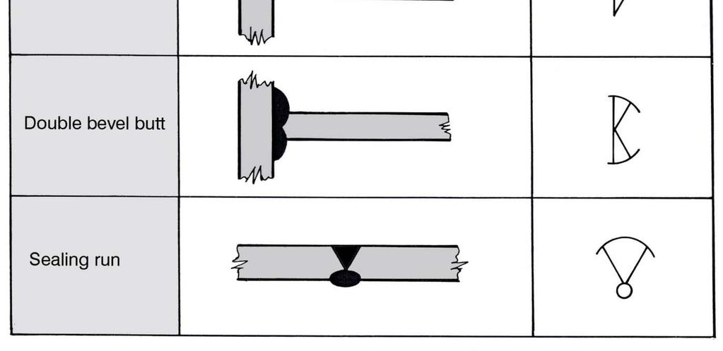
15 Section 5.7 Symbols
RULES FOR THE CLASSIFICATION OF SHIPS
 RULES FOR THE CLASSIFICATION OF SHIPS 2009 Part 26 - WELDING Amendments No.1 CROATIAN REGISTER OF SHIPPING Hrvatska (Croatia) 21000 Split Marasovićeva 67 P.O.B. 187 Tel.: (...) 385 (0)21 40 81 11 Fax.:
Qualification scheme for welders of aluminium alloys
 (March 2009) Qualification scheme for welders of aluminium alloys 1. Scope 1.1 This document provides guidance for a qualification scheme for welders intended to be engaged in welding of aluminium alloys
WELDING PROCEDURE SPECIFICATION. Shielded Metal Arc Welding-SMAW
 WELDING PROCEDURE SPECIFICATION Shielded Metal Arc Welding-SMAW WPS Number: WPS-SMAW-CS Revision: 0 Company Name & Address ABC WELDING & FABRICATING 123 WeldProc Boulevard Toronto, ON A1B 2C3 CWB Approval
Hull Surveys for Liquefied Gas Carriers
 (May 2007) (Rev.1 Nov 2007) (Rev.2 Mar 2009) (Rev.3 July 2011) Hull Surveys for Liquefied Gas Carriers CONTENTS 1. General 1.1 Application 1.2 Definitions 1.3 Repairs 1.4 Thickness measurements and close-up
Qualification scheme for welders of hull structural steels
 (Sept 2016) Qualification scheme for welders of hull structural steels 1. Scope 1.1 This document gives requirements for a qualification scheme for welders intended to be engaged in the fusion welding
71T1 - Gas Shielded Flux Cored Welding Wire Provides excellent performance in all position welding. Weld Metal - Chemistry
 Flux Cored Wire 71T1 - Gas Shielded Flux Cored Welding Wire Provides excellent performance in all position welding Description: Provides a stable arc, low spatter, easy to remove slag, and neat weld metal.
QC Inspection and Qualification Procedure- TX-EDU-VT-1-07, Revision # by Richard J DePue, Supersedes IW-VT-1 Visual Inspection Procedure
 1.0 Scope: QC Inspection and Qualification Procedure- TX-EDU-VT-1-07, Revision #6 03-04-2016 by Richard J DePue, Supersedes IW-VT-1 Visual Inspection Procedure The purpose of this procedure is to define
INSPECTION OF FIELD WELDING
 INSPECTION OF FIELD WELDING Objective Types of Projects Involving Welding Common Welding Terms & Symbols Welder Qualifications Common Welding Requirements Welding Inspection Types of Projects Involving
Comparison of. No.47 Shipbuilding and Repair Quality Standard (1996) (Rev. 1, 1999) (Rev.2, Dec. 2004) with
 (Rev. 1, 1999) (Rev.2, Dec. 2004) with") Comparison of No.47 Shipbuilding and Repair Quality Standard (1996) (Rev. 1, 1999) (Rev.2, Dec. 2004) with Japan Shipbuilding Quality Standard (, 1004, Appendix 0144) and Production Standard of the German
Comparison of No.47 Shipbuilding and Repair Quality Standard (1996) (Rev. 1, 1999) (Rev.2, Dec. 2004) with Japan Shipbuilding Quality Standard (, 1004, Appendix 0144) and Production Standard of the German
AASHTO/AWS D1.5M/D1.5:2008. Table of Contents
 Table of Contents Personnel...v Foreword...ix List of Tables... xviii List of Figures...xix List of Forms...xxi 1. General Provisions...1 1.1 Application...1 1.2 Base Metal...1 1.3 Welding Processes...1
No.47 Shipbuilding and Repair Quality Standard (1996) (Rev. 1, 1999) (Rev.2, Dec. 2004) (Rev.3, Nov. 2006) (Rev.4, Aug. 2008)
 (Rev. 1, 1999) (Rev.2, Dec. 2004) (Rev.3, Nov. 2006) (Rev.4, Aug. 2008)") No.47 Shipbuilding and Repair Quality Standard (1996) (Rev. 1, 1999) (Rev.2, Dec. 2004) (Rev.3, Nov. 2006) (Rev.4, Aug. 2008) Part A Shipbuilding and Remedial Quality Standard for New Construction Part
No.47 Shipbuilding and Repair Quality Standard (1996) (Rev. 1, 1999) (Rev.2, Dec. 2004) (Rev.3, Nov. 2006) (Rev.4, Aug. 2008) Part A Shipbuilding and Remedial Quality Standard for New Construction Part
Cast Steel Propellers W27. (May 2000) (Rev.1 May 2004)
 (Rev.1 May 2004)") (May 2000) (Rev.1 May 2004) Cast Steel Propellers 1. Scope 1.1 These unified requirements are applicable to the manufacture of cast steel propellers, blades and bosses. 1.2 Where the use of alternative
(May 2000) (Rev.1 May 2004) Cast Steel Propellers 1. Scope 1.1 These unified requirements are applicable to the manufacture of cast steel propellers, blades and bosses. 1.2 Where the use of alternative
PART UF REQUIREMENTS FOR PRESSURE VESSELS FABRICATED BY FORGINGS
 p 1 of 6 UF-1 UF-12 PART UF REQUIREMENTS FOR PRESSURE VESSELS FABRICATED BY FORGING the test temperature be higher than 20 F ( 29 C). Certification is required. An ultrasonic examination shall be made
Section 906. STRUCTURAL STEEL
 906.01 Section 906. STRUCTURAL STEEL 906.01. General Requirements. Finished rolled shapes must be free from imperfections that affect strength and durability in accordance with ASTM A 6. Rolled shapes
Gases for welding carbon and low-alloy steels.
 Carbon & low alloy steels - New Zealand edition Shielding gas. Gases for welding carbon and low-alloy steels. 03 Steel forms the largest and most widely used group of structural and engineering alloys
No.47 Shipbuilding and Repair Quality Standard (1996) (Rev. 1, 1999) (Rev.2, Dec. 2004) (Rev.3, Nov. 2006)
 (Rev. 1, 1999) (Rev.2, Dec. 2004) (Rev.3, Nov. 2006)") No.47 Shipbuilding and Repair Quality Standard (1996) (Rev. 1, 1999) (Rev.2, Dec. 2004) (Rev.3, Nov. 2006) Part A Shipbuilding and Repair Quality Standard for New Construction Part B Repair Quality Standard
No.47 Shipbuilding and Repair Quality Standard (1996) (Rev. 1, 1999) (Rev.2, Dec. 2004) (Rev.3, Nov. 2006) Part A Shipbuilding and Repair Quality Standard for New Construction Part B Repair Quality Standard
RULES FOR MATERIALS AND WELDING
 CCS Rule Change Notice For: RULES FOR MATERIALS AND WELDING Version: September 2017. RCN No.1 Effective date: 1 January, 2018 Beijing 1 PART ONE METALLIC MATERIALS CHAPTER 3 STEEL PLATES,FLAT BARS AND
WELDER S. Visual Inspection HANDBOOK. May 2013
 WELDER S Visual Inspection HANDBOOK May 2013 -- NOTE -- This handbook is NOT intended to serve as a work procedure or to replace any existing procedures. It is solely intended to provide basic information
EXTRA HIGH STRENGTH STEEL MATERIAL NV 47 FOR HULL STRUCTURAL APPLICATION IN CONTAINER SHIPS
 CLASSIFICATION NOTES No. 30.10 EXTRA HIGH STRENGTH STEEL MATERIAL NV 47 FOR HULL STRUCTURAL APPLICATION IN CONTAINER SHIPS MAY 2011 The content of this service document is the subject of intellectual property
EML 2322L -- MAE Design and Manufacturing Laboratory. Welding
 EML 2322L -- MAE Design and Manufacturing Laboratory Welding Intro to Welding A weld is made when separate pieces of material to be joined combine and form one piece when heated to a temperature high enough
LAGUARDIA COMMUNITY COLLEGE - CUNY August 3, 2009
 SECTION 051200 - STRUCTURAL STEEL FRAMING PART 1 - GENERAL 1.01 SUMMARY A. Drawings and general provisions of the Contract, including General and Supplementary Conditions and other Division 1 Specification
CHAPTER 3: TYPES OF WELDING PROCESS, WELD DEFECTS AND RADIOGRAPHIC IMAGES. Welding is the process of coalescing more than one material part at
 41 CHAPTER 3: TYPES OF WELDING PROCESS, WELD DEFECTS AND RADIOGRAPHIC IMAGES 3.0. INTRODUCTION Welding is the process of coalescing more than one material part at their surface of contact by the suitable
Part A Shipbuilding and Remedial Quality Standard for New Construction PART A - SHIPBUILDING AND REMEDIAL QUALITY STANDARDS FOR NEW CONSTRUCTION
 No.47 Shipbuilding and Repair Quality Standard (1996) (Rev. 1, 1999) (Rev.2, Dec. 2004) (Rev.3, Nov. 2006) (Rev.4, Aug. 2008) (Rev.5, Oct. 2010) (Rev.6, May 2012) Part A Shipbuilding and Remedial Quality
ISO INTERNATIONAL STANDARD. Approval testing of welders Fusion welding Part 4: Nickel and nickel alloys
 INTERNATIONAL STANDARD ISO 9606-4 First edition 1999-04-01 Approval testing of welders Fusion welding Part 4: Nickel and nickel alloys Épreuve de qualification des soudeurs Soudage par fusion Partie 4:
Welding Inspection Defects/Repairs Course Reference WIS 5
 Copy from Welding Inspection Defects/Repairs Course Reference WIS 5 Weld Defects Defects which may be detected by visual inspection can be grouped under five headings Cracks Surface irregularities Contour
WE11S GMA (MIG) Fillet Weld
 Fillet Weld") Uniform Procedures For Collision Repair WE11S GMA (MIG) Fillet Weld 1. Description This procedure describes methods for making and inspecting GMA (MIG) fillet welds on automotive steel. 2. Purpose The
Uniform Procedures For Collision Repair WE11S GMA (MIG) Fillet Weld 1. Description This procedure describes methods for making and inspecting GMA (MIG) fillet welds on automotive steel. 2. Purpose The
Materials and Qualification Procedures for Ships
 Materials and Qualification Procedures for Ships Approval of Works for the Manufacture of Fusion Welded Pressure Vessels Revision 4, July 2015 Page 1 of 17 Lloyd s Register Group Limited, its subsidiaries
Fundamentals for Steel Constructions
 Fundamentals for Steel Constructions 1. General design principles applicable to welded constructions 2. Frames, girders, etc. 3. Sheet metal construction, box girder 4. Drafting 5. Common welds at Broetje-Automation
QUALIFICATION TESTING OF FIELD WELDERS
 Page 1 of 9 Oklahoma DOT Materials & Testing December 5, 2003 (Updated to Reference 2009 Specifications 11/26/2012) (Added paragraph to the bottom of Roles and Responsibilities section. 11/14/2017) Publication:
Review of EN ISO
 Svetskommissionen Review of EN ISO 9606-1 Qualification testing of welders Fusion welding Purpose: Ensure the ability of a welder to follow written instructions and verify the welders skill. These are
DNVGL-CG-0287 Edition December 2015
 CLASS GUIDELINE DNVGL-CG-0287 Edition December 2015 The electronic pdf version of this document, available free of charge from http://www.dnvgl.com, is the officially binding version. FOREWORD DNV GL class
AWS B1.10:1999 An American National Standard. Guide for the Nondestructive Examination of Welds
 AWS B1.10:1999 An American National Standard Guide for the Nondestructive Examination of Welds Key Words Guide, eddy current examination, magnetic particle examination, nondestructive examination, penetrant
REMOVAL OF CAST LIP STEP 1 STEP 2. Layout cut lines, based on existing welds and verify with dimension taken from new lip. STEP 3
 REMOVAL OF CAST LIP STEP 1 fig. 1-1 Brace clam from cheek plate to cheek plate (A). Brace clam from bucket floor, (just behind back of lip joint), to upper cheek plate on both sides (B). The purpose of
Approval testing of welders working to approved welding procedures
 BRITISH STANDARD BS 4871-3: 1985 Specification for Approval testing of welders working to approved welding procedures Part 3: Arc welding of tube to tube-plate joints in metallic materials UDC 621.791.007.2:331.108.376:
WE01A GMA (MIG) Plug Weld
 Plug Weld") Uniform Procedures For Collision Repair WE01A GMA (MIG) Plug Weld 1. Description This procedure describes methods for making and evaluating gas metal arc (GMA) plug welds (MIG plug welds) on all types
Uniform Procedures For Collision Repair WE01A GMA (MIG) Plug Weld 1. Description This procedure describes methods for making and evaluating gas metal arc (GMA) plug welds (MIG plug welds) on all types
Engineering Branch Assets Delivery Group
 F.1 SCOPE This Technical Specification shall apply to Fibre Reinforced Plastics or Glass Reinforced Plastics (hereinafter referred to as FRP or GRP) structures and the materials used in their manufacture,
Requirements for Welding Consumables for Aluminium Alloys
 (July, 1999) (Rev.1 June 2005) Requirements for Welding Consumables for Aluminium Alloys 1. General 1.1 Scope 1.1.1 hese requirements give the conditions of approval and inspection of welding consumables
Welding Recommendations for welding of metallic materials Part 8: Welding of cast irons BS EN :2004 Incorporating Corrigendum No.
 BRITISH STANDARD Welding Recommendations for welding of metallic materials Part 8: Welding of cast irons The European Standard EN 1011-8:2004 has the status of a British Standard ICS 25.160.10 BS EN 1011-8:2004
1. Poor attitude toward any of the other students, instructors, or judges. 2. Failure to use personal protective equipment (PPE).
.") Welding Contest Rules and Score Sheet 2016 4G Rules: 1. Be Safe & Have Fun 2. Can tack in any position but groove welding must be in accordance with your WPS. 3. Can use wire brush, chipping hammer, and
Welding Contest Rules and Score Sheet 2016 4G Rules: 1. Be Safe & Have Fun 2. Can tack in any position but groove welding must be in accordance with your WPS. 3. Can use wire brush, chipping hammer, and
ISO INTERNATIONAL STANDARD
 INTERNATIONAL STANDARD ISO 10675-1 First edition 2008-03-01 Non-destructive testing of welds Acceptance levels for radiographic testing Part 1: Steel, nickel, titanium and their alloys Essais non destructifs
Lecture 23. Chapter 30 Fusion Welding Processes. Introduction. Two pieces are joined together by the application of heat
 Lecture 23 Chapter 30 Fusion Welding Processes Introduction Fusion welding Two pieces are joined together by the application of heat Melting and fusing the interface Filler metal Extra metal added (melted)
AWS B1.10M/B1.10:2009 An American National Standard. Guide for the Nondestructive Examination of Welds
 An American National Standard Guide for the Nondestructive Examination of Welds An American National Standard Approved by the American National Standards Institute July 1, 2009 Guide for the Nondestructive
G009: Remove weld metal from plain carbon steel, using weld washing techniques.
 Welding 1 st Quarter DUTY A: Practicing Occupational Orientation A001: Follow safe practices. A002: Prepare time or job cards, reports, or records. A003: Perform housekeeping duties. A004: Follow oral
SPECIFICATIONS FOR BRIDGE CONSTRUCTION SECTION 5 REINFORCING STEEL. 5.1 General Certification Fabrication...
 SPECIFICATIONS FOR BRIDGE CONSTRUCTION SECTION 5 REINFORCING STEEL TABLE OF CONTENTS 5.1 General...5-1 5.2 Certification...5-1 5.3 Fabrication...5-1 5.4 Handling and Storage...5-1 5.5 Field Repair of Epoxy
ISO INTERNATIONAL STANDARD. Non-destructive testing of welds Visual testing of fusion-welded joints
 INTERNATIONAL STANDARD ISO 17637 First edition 2003-07-15 Non-destructive testing of welds Visual testing of fusion-welded joints Contrôle non destructif des assemblages soudés Contrôle visuel des assemblages
Welding Unit 2 La Plata County. Guided Project
 Welding Unit 2 La Plata County Guided Project Second Year Welding Guidelines The 4-h wielding project is intended to give the 4-H members the fundamental background in the major aspects of welding. The
SPECIFICATION FOR STRUCTURAL STEELWORK
 SPECIFICATION FOR STRUCTURAL STEELWORK 1.0 SCOPE OF WORK The work covered by this section of the Specifications consists of furnishing all plants, labour, equipment, supervision, appliances and materials,
Application of Narrow Gap Welding Process with High Speed Rotating Arc to Box Column Joints of Heavy Thick Plates
 JFE TECHNICAL REPORT No. 14 (Dec. 2009) Application of Narrow Gap Welding Process with High Speed Rotating Arc to Box Column Joints of Heavy Thick Plates IWATA Shinji *1 MURAYAMA Masatoshi *2 KOJIMA Yuji
1. IMPERFECTIONS OF THE WELDED CONNECTION
 1. IMPERFECTIONS OF THE WELDED CONNECTION A. Classification of imperfections in the welds acc. to EN 26520 (ISO 6520) Crack (100) - imperfection produced by a local rupture in the solid state which can
welder certification welder performance qualification
 Chapter 29 Welder Certification OBJECTIVES After completing this chapter, the student should be able : Explain welder qualification and certification. Outline the steps required certify a welder. Make
HYUNDAI WELDING CO., LTD.
 Rev. 04 SUBMERGED ARC WELDING CONSUMABLES FOR WELDING OF Mild & 490MPa CLASS HIGH TENSILE STEEL HYUNDAI WELDING CO., LTD. Specification AWS A5.17 F7A0-EH14 KS ISO 14174 S A AR 1 JIS EN Z3352 S A AR 1 /
ISO INTERNATIONAL STANDARD
 INTERNATIONAL STANDARD ISO 15614-2 First edition 2005-05-15 Specification and qualification of welding procedures for metallic materials Welding procedure test Part 2: Arc welding of aluminium and its
DELIVERING THE SOLUTIONS YOU NEED TO STAY PRODUCTIVE
 E S CO ST Y L E S U P E R - V B U C K E T T E E T H DELIVERING THE SOLUTIONS YOU NEED TO STAY PRODUCTIVE E S CO ST Y L E S U P E R - V T E E T H & A DA P T E R S 2-STRAP ADAPTERS Part No A B C D KG Machine
Chapter 12. Flux Cored Arc Welding Equipment, Setup, and Operation Delmar, Cengage Learning
 Chapter 12 Flux Cored Arc Welding Equipment, Setup, and Operation Objectives Explain the FCA welding process Describe what equipment is needed for FCA welding List the advantages of FCA welding, and explain
RULES FOR THE CLASSIFICATION OF SHIPS
 RULES FOR THE CLASSIFICATION OF SHIPS 2013 Part 2 - HULL Amendments No. 1 CROATIAN REGISTER OF SHIPPING Hrvatska (Croatia) 21000 Split Marasovićeva 67 P.O.B. 187 Tel.: (...) 385 (0)21 40 81 11 Fax.: (...)
Requirements for Use of Extremely Thick Steel Plates in Container Ships
 (Jan 2013) (Rev.1 Sept 2015) Requirements for Use of Extremely Thick Steel Plates in Container Ships 1. Application 1.1 General 1.1.1 This UR is to be complied with for container ships incorporating extremely
Table of Contents. List of Drawings
 SCOPE OF WORK Hastings Stadium Exhibition Park, 81 London Road, Guelph, Ontario Structural and Maintenance Remedial Work Prepared For City of Guelph City Hall, 1 Carden Street, Guelph, ON N1H 3A1 Prepared
Joining. 10. Tool Design for Joining. Joining. Joining. Physical Joining. Physical Joining
 Joining 10. Tool Design for Joining Nageswara Rao Posinasetti The joining processes are generally divided into two classes: mechanical and physical. Mechanical joining does not ordinarily involve changes
DRAFT UGANDA STANDARD
 DRAFT UGANDA STANDARD DUS1910-2 First Edition 2017-10-20 Metal Chairs for 0ffice Purposes Part. 2: Revolving and Tilting- Specification Reference number DUS 1910-2:2017 UNBS 2017 DUS 1910-2:2017 Compliance
ANSI/AWS D R An American National Standard. Recommended Practices for Root Pass Welding of Pipe Without Backing
 ANSI/AWS D10.11-87R An American National Standard Recommended Practices for Root Pass Welding of Pipe Without Backing Key WordS Root pass welding, pipe, gas purging, consumable inserts, gas tungsten arc,
Hardfacing Electrodes. Special tubular construction requiring low operating currents. Hardness : 650/700 HB.
 Hardfacing Electrodes Special tubular construction requiring low operating currents. Hardness : 650/700 HB. These electrodes have been engineered to provide extended service life at ambiant and elevated
Metallurgical Processes
 Metallurgical Processes Chapter Thirty One: Welding Processes Dr. Eng. Yazan Al-Zain Department of Industrial Engineering 1 Introduction Welding processes divide into two major categories: Fusion Welding:
THE APPLICATION OF FRICTION STIR WELDING (FSW) OF ALUMINIUM ALLOYS IN SHIPBUILDING AND RAILWAY INDUSTRY
 OF ALUMINIUM ALLOYS IN SHIPBUILDING AND RAILWAY INDUSTRY") Journal of KONES Powertrain and Transport, Vol. 24, No. 2 2017 THE APPLICATION OF FRICTION STIR WELDING (FSW) OF ALUMINIUM ALLOYS IN SHIPBUILDING AND RAILWAY INDUSTRY Grzegorz Gesella, Mirosław Czechowski
Journal of KONES Powertrain and Transport, Vol. 24, No. 2 2017 THE APPLICATION OF FRICTION STIR WELDING (FSW) OF ALUMINIUM ALLOYS IN SHIPBUILDING AND RAILWAY INDUSTRY Grzegorz Gesella, Mirosław Czechowski
This document is a preview generated by EVS
 INTERNATIONAL STANDARD ISO 15614-8 Second edition 2016-03-01 Specification and qualification of welding procedures for metallic materials Welding procedure test Part 8: Welding of tubes to tube-plate joints
Design for welding: Design recommendations
 Design for welding: Design recommendations Arc welding can be used to weld almost any kind of assembly, including even complex structures. Arc weldments use a wide variety of ferrous and non ferrous metals.
Flux Cored Wire (FCW)
") Flux Cored Wire (FCW) Gas Shielded Type Flux Cored Wire (FCAW) Welding Consumables Selection Product name Specification Characteristic description GMX70 E70T-1C CO 2, DC+, high de rate titania type, only
Flux Cored Wire (FCW) Gas Shielded Type Flux Cored Wire (FCAW) Welding Consumables Selection Product name Specification Characteristic description GMX70 E70T-1C CO 2, DC+, high de rate titania type, only
Materials & Processes in Manufacturing
 2003 Bill Young Materials & Processes in Manufacturing ME 151 Chapter 37 Arc Processes Chapter 38 Resistance Welding Chapter 39 Brazing and Soldering 1 Introduction Arc welding processes produce fusion
These elements are in carbon steels in minimal amounts, usually less than 1%.
 Alloy Steels Weld Tech News VOL 1. NO. 11 WELD TECH NEWS is a newsletter for welders working primarily in maintenance and repair. Each issue contains useful information on materials (cast irons, steels,
INSPECTION and TESTING of WELDS & Acceptance Standard
 INSPECTION and TESTING of WELDS & BY A.K.BOSE CONSULTANT Topics of Discussion Important Definitions related to Welding Weld Inspection- Before, During and After Weld Inspection Instruments and Gauges Common
Section 12 - Welding Consumables 1. Welding of Carbon Steels 2. MMA Electrodes 24. MIG/MAG Wires 44. MIG & TIG Wires for CMn & Low Alloy Steels 50
 Carbon Steels 1 Afrox Product Reference Manual Carbon Steels Section - 1 Carbon Steels 1 Welding of Carbon Steels 2 MMA Electrodes 24 MIG/MAG Wires 44 MIG & TIG Wires for CMn & Low Alloy Steels 50 Flux
ITEM 458 WATERPROOFING FOR STRUCTURES
 ITEM 458 WATERPROOFING FOR STRUCTURES 458.1. Description. This Item shall govern for the furnishing and placing of waterproofing on concrete and steel bridge decks of railroad structures and on other structures
Technical Service. INSTALLATION INSTRUCTIONS FOR TARAFLEX SPORT PRODUCTS over Gypsum base Products. This document refers to the following products:
 INSTALLATION INSTRUCTIONS FOR TARAFLEX SPORT PRODUCTS over Gypsum base Products This document refers to the following products: Product Width Width Ft. Installation direction Seams treatment Taraflex Surface
3/26/2015. Processes of Arc Welding. Kate Gilland
 3/26/2015 Processes of Arc Welding Kate Gilland Processes of Arc Welding Introduction Welding is a powerful technological advance. It allows for things to be conjoined that may have not been thought to
Welding Processes. Consumable Electrode. Non-Consumable Electrode. High Energy Beam. Fusion Welding Processes. SMAW Shielded Metal Arc Welding
 Fusion Consumable Electrode SMAW Shielded Metal Arc Welding GMAW Gas Metal Arc Welding SAW Submerged Arc Welding Non-Consumable Electrode GTAW Gas Tungsten Arc Welding PAW Plasma Arc Welding High Energy
Multi-Purpose Mechanized Welding Carriage
 WEL-HANDY MULTI Multi-Purpose Mechanized Welding Carriage Feature & Benefits Two Models Available Standard and Programmable Stitch/Tack Multi Weld Process Standard and Programmable Stitch/Tack Multiple
ASME B31.3 Process Piping
 ASME B31.3 Process Piping Charles Becht IV, PhD, PE Don Frikken, PE Instructors BECHT ENGINEERING COMPANY, INC. Fabrication and Installation - 1 Piping Development Process 1. Establish applicable system
PIPE AND TUBE RAILINGS
 SECTION 05521 - PIPE AND TUBE RAILINGS PART 1 GENERAL 1.01 RELATED DOCUMENTS A. Drawings and general provisions of the Contract, including General and Supplementary Conditions and Division 1 Specification
SECTION COMMON WORK RESULTS FOR CONCRETE SSPECIALTY COATINGS
 SECTION 03 05 00 COMMON WORK RESULTS FOR CONCRETE 09 97 00 SSPECIALTY COATINGS Weld Crete ************************************************************************************************************************
B. Polyethylene samples shall be submitted for Owner approval of color and quality.
 Glass Rail ENGINEERED DASHERBOARD SPECIFICATIONS PART 1 - GENERAL 1.01 PROJECT SCOPE A. Contractor shall furnish and install one complete set of steel framed dasherboards as indicated on the drawings and
Product Booklet Keen K-1000CS FCAW Wire Coil and TIG Filler Wire Storage Oven Floor Positioned
 Product Booklet Keen K-1000CS FCAW Wire Coil and TIG Filler Wire Storage Oven Floor Positioned Purpose: To prevent moisture contamination in spooled welding wire and TIG filler rods Capacity: 8 / 10 lb
Structural Design of a Containership Approximately 3100 TEU According to the Concept of General Ship Design B-178
 Structural Design of a Containership Approximately 3100 TEU According to the Concept of General Ship Design B-178 W.Souadji, Zbigniew Sekulski, B.Hamoudi 1 Abstract The design developed in this work is
COMMON STRUCTURAL RULES FOR DOUBLE HULL OIL TANKERS WITH LENGTH 150 METRES AND ABOVE
 RULES FOR CLASSIFICATION OF SHIPS IACS COMMON STRUCTURAL RULES PART 8 CHAPTER 1 COMMON STRUCTURAL RULES FOR DOUBLE HULL OIL TANKERS WITH LENGTH 150 METRES AND ABOVE JANUARY 008 This booklet includes the
Radiographic Inspection
 The Practical Reference Guide for Radiographic Inspection Acceptance Criteria THE PRACTICAL REFERENCE GUIDE for RADIOGRAPHIC INSPECTION ACCEPTANCE CRITERIA Located, reviewed and reformatted under the AWS
Licensed Copy: Rajeev Bhandari, Bechtel Ltd, 12 April 2004, Uncontrolled Copy, (c) BSI
 BSI") BRITISH STANDARD BS EN 287-1:2004 Qualification test of welders Fusion welding Part 1: Steels The European Standard EN 287-1:2004 has the status of a British Standard ICS 25.160.10 BS EN 287-1:2004 This
BRITISH STANDARD BS EN 287-1:2004 Qualification test of welders Fusion welding Part 1: Steels The European Standard EN 287-1:2004 has the status of a British Standard ICS 25.160.10 BS EN 287-1:2004 This
Hull and machinery steel forgings
 (1978) (Rev.1 1980) (Rev.2 July 2002) (Rev.3 May 2004) Hull and machinery steel forgings.1 Scope.1.1 These requirements are applicable to steel forgings intended for hull and machinery applications such
Lecture 3-1: Hull production - Product hierarchy and block division
 Kul-24.4130 Shipyard engineering Lecture 3-1: Hull production - Product hierarchy and block division Applied Mechanics Marine Technology Lecture in course contents Production planning Introduction Shipbuilding
Solid-State Welding Processes
 Solid-State Welding Processes Text Reference: Manufacturing Engineering and Technology, Kalpakjian & Schmid, 6/e, 2010 Chapter 31 Solid-State State Welding Processes Joining takes place without fusion
Standards for Welding
 NEW CATALOGUE Standards for Welding Specifications, procedures and tests for use by welders, quality controllers and manufacturers Equipping business with knowledge Standards for Welding Specifications,
5. POST-EARTHQUAKE INSPECTION
 5. POST-EARTHQUAKE INSPECTION When required by the building official, or recommended by the Interim Guidelines in Chapter 4, post-earthquake inspections of buildings may be conducted in accordance with
Introduction. Online course on Analysis and Modelling of Welding. G. Phanikumar Dept. of MME, IIT Madras
 Introduction Online course on Analysis and Modelling of Welding G. Phanikumar Dept. of MME, IIT Madras Classification of Manufacturing Processes Manufacturing Processes Ingot Casting Shape Casting Power
MIG/MAG machine range
 MIG/MAG machine range The MIG/MAG applications are used in various domains from the simple carriage for shipyard industry to large gantry for train manufacturing. The choice of the machine depends mainly
Structural Steel Welding
 PDH Course S150 Structural Steel Welding Semih Genculu, P.E. 2011 PDH Online PDH Center 5272 Meadow Estates Drive Fairfax, VA 22030-6658 Phone & Fax: 703-988-0088 www.pdhonline.org www.pdhcenter.com An
Standard Recommended Practice
 NACE Standard RP0178-2003 Item No. 21022 Standard Recommended Practice Fabrication Details, Surface Finish Requirements, and Proper Design Considerations for Tanks and Vessels to Be Lined for Immersion
Optimization of Titanium Welding used in Aircrafts
 Optimization of Titanium used in Aircrafts Prof. Anand Lahane 1, Shubham Devanpalli 2, Ritesh Patil 3, Suraj Thube 4 1 Assistant Professor, Dept. of Mechanical Engineering, Shatabdi Institute of Engineering