FEM SIMULATION AND EXPERIMENTAL VALIDATION OF FLASH-LESS COLD FORGING FOR PRODUCING AUV PROPELLER BLADE *
|
|
|
- Audra Shields
- 6 years ago
- Views:
Transcription
1 IJST, Transactions of Mechanical Engineering, Vol. 36, No. M1, pp 1-12 Printed in The Islamic Republic of Iran, 2012 Shiraz University FEM SIMULATION AND EXPERIMENTAL VALIDATION OF FLASH-LESS COLD FORGING FOR PRODUCING AUV PROPELLER BLADE * H. M.T. KHALEED 1** Z. SAMAD 1, M. A. MUJEEBU 1, A. BADARUDDIN 2, I. A. BADRUDDIN 2, A.B. ABDULLAH 1 AND N. J. SALMAN AHMED 2 1 School of Mechanical Eng., Universiti Sains Malaysia, Eng. Campus, Nibong Tebal, Penang, Malaysia khalid_tan@yahoo.com 2 Dept. of Mechanical Eng., University of Malaya, Kuala Lumpur, Malaysia Abstract Manufacturing of the Autonomous Underwater Vehicle (AUV) is a challenge for researchers because of the hazardous ocean environment. The propeller is the most complex part in AUV because of its elaborately shaped blade designed to increase the thrust. The selection of the manufacturing process, flash-less cold forging die design and optimization of the work-piece are the major issues to reduce the overall cost of the propeller. Numerous investigations have been carried out in this area by many researchers using various tools and techniques. However, cold forging of complex geometries such as the propeller blade is still lacking. Moreover, volumetric analysis and optimization of work-piece have not been reported so far for complex geometries. In this work, the cold forging process is adopted to produce the propeller blade. Three-dimensional finite element (FE) analysis and experimental flash-less cold forging of aluminum blade of the AUV propeller is presented. The work-piece used is of AISI AL6061 and the die material is die steel (AISI D2).Based on the simulation results, the flash-less cold forging is successfully done on a 100 ton C-type machine. Keywords Autonomous under water vehicle, cold forging, FEM, flash-less, under- 1. INTRODUCTION Autonomous underwater vehicle (AUV) is an unmanned, tether-free vehicle which is powered by battery or fuel cell [1]. The direction of AUV is controlled by preprogrammed computers utilizing various navigation sensors such as inertial measurement unit, sonar sensor, laser ranger, pressure sensor, etc. Research on AUV has become very important and there has been increased interest as well among the marine researchers in the last two decades. The demand in the current market is tremendous for AUV; hence researchers are working to fulfil this requirement. It is reported that in the 1990s, 30 AUVs were developed by researchers around the world [2]. Because of its ability to do the task independently, researchers have used it for various applications such as ecology survey and sea bed mapping. It has been reported by many researchers that AUV could be used successfully in hazardous conditions like Deep Ocean [2]. The AUV system is an integration of some essential subsystems. Propulsion system is one of these subsystems. In practice, the propulsion system of AUV contains a propeller and an electric motor (Marsh 2004) [3].Some researchers have determined the aspect ratios that fill the die cavity using FEM and neural networks, but have not discussed flash [4]. Similarly, [5] and [6] also worked on no under and flash-less forging. No under and no folding lead to net shape forging. Tomov and [7] presented the net shape forging, but did not report the Received by the editors August 1, 2010; Accepted August 11, Corresponding author
2 2 H. M. T. Khaleed et al. flash minimization. For propeller blades, achieving net shape without flash is difficult. The hot forging of aerofoil blades was performed by Hu et al [8], who modeled smooth Bezier surfaces using Abaqus/Explicit FE software. They measured aerofoil blade flash at several regions and found the flash ranging from 40%-90% at various regions, and thus caused a greater wastage of material. The flash-less cold forging is defined as the one in which the amount of flash is minimal.similar work has been done by [9-15]. Even though many researchers have focused on various manufacturing processes to produce the AUV propeller, like machining, casting, injection molding and hot forging, an attempt for cold forging of complex geometries such as AUV propeller blades has not been reported. Optimization of the work-piece to achieve flash-less forging for complex profile and stress analysis of induced stresses is to be studied thoroughly. Moreover, research is required to be done in die design, especially cold forging die because the die will undergo high loads; hence it has to undergo stress analysis. The work-piece has to be optimized for forging the propeller blade for flash-less forging with no under to increase the die life, to reduce the number of operations and to obtain dimensional accuracy. Predominant complexity in the propeller blade is hydrodynamic profile and twist because it is very troublesome to achieve the flashless forging, especially in cold forging. Approaches: The study was carried out to analyze the process and design the cold forging die as per the dimension of the designed geometry, by using FEM technique and experimental analysis; SOLID WORKS and DEFORM-F3 software are used for design and for analysis respectively. The optimization of pre-form for the propeller blade was done by varying the design parameter. Experimental method has also been used to validate simulation results. 2. OPTIMIZATION OF WORK-PIECE FOR FRONT HUB Figure 1 shows the flow diagram for the whole process of optimization of work piece without under. It starts with developing the mathematical equation for the work-piece to achieve the flash-less forging and then develops the CAD model of the work-piece. This model is then transferred to the FEM environment and analyzed for flash. If no flash is observed the under is then checked for the process. If no under is found then stop the process, otherwise the process is repeated till no under is achieved. The flash, under and load is observed for hubs and blade by keeping one parameter constant and the others varied. In the case of the blade, the flash and under are studied for pre-form 1 by keeping the area constant, and the thickness of the work-piece is varied. For pre-form 2 the thickness of the work-piece is kept constant and the area is varied. Further, for pre-form 3 flash thicknesses are varied, and the area and thickness of the work-piece are kept constant. 3. RESULTS AND DISCUSSION In this section the under and flash are studied for the blade. The pre-forms, Pre-form 1 and Pre-form 2, are tested and the under and flash are observed for five different values of work-piece thickness t wp (cases I, II, III, IV and V respectively) and the results are summarized in Table 1. The work-piece volume, observed flash and under are noticed from DEFORM. The flash volume is observed from the DEFORM for case I, II and III, since both under flash occur. For case IV and V no under is observed, hence the flash volume is calculated by subtracting the designed volume from the work-piece volume. IJST, Transactions of Mechanical Engineering, Volume 36, Number M1 April 2012
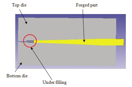
3 FEM simulation and experimental validation of 3 Start Developing the mathematical equation Modeling of designed forging components and work-piece in SOLID WORKS and parameter variation of work-piece Models transfer to FEM package DEFROM3D and analysis Optimization of work-piece If under and flash are observed Yes No End Fig. 1. Flow diagram for optimizing the work-piece Table 1. Work-piece volume, flash volume, under volume and design volume of Pre-form 1 for various thicknesses when A wp = mm 2 flash thickness t f = 0.5mm Cases t wp (mm) Work-piece volume DEFORM Flash volume for no under Designed volume Observed flash Under I Flash with Less More under II Flash with Less Medium under III Flash with Medium Less under IV More No under V More No under Figures 2-6 show the sectional views of the respective simulated forged models for Pre-form1. For case I, case II and case III, a slight under is observed at the top and bottom side of the cavities. April 2012 IJST, Transactions of Mechanical Engineering, Volume 36, Number M1

 is observed at the flash zone as shown in Figure 4.14. Hence it is concluded that optimum thickness is 3mm to achieve no under.")


4 4 H. M. T. Khaleed et al. However, for case I, the flash is observed at the back side of the blade as shown in Fig. 2b, and under is observed at the top and left side of the flash zone too as evident from Fig. 2a. For case IV, no under is found but a flash of mm 3 (Table 1) is observed at the flash zone as shown in Figure Hence it is concluded that optimum thickness is 3mm to achieve no under. Fig. 2. Case I cross section view along the width flash at back side of pre-form 1 Fig. 3. Case II cross section view of pre-form 1 along the width Fig. 4. Case III cross section view of preform 1 along the width Fig. 5. Case IV cross section view of pre-form 1 along the width Fig. 6. Case V cross section view of pre-form 1 along the width However, there is a flash which is to be minimized by varying work-piece area A wp as mentioned in Section 3.3. For this purpose, Pre-form 2 is made with a reduced A wp and tested for five different A wp (cases I, II, III, IV and V) and the results are tabulated in Table 2. Figures, 7-11 show the sectional views IJST, Transactions of Mechanical Engineering, Volume 36, Number M1 April 2012


5 FEM simulation and experimental validation of 5 of the simulated models of Pre-form 2 for the five cases. For case I under is observed at the left and right flash zones and at the left side flash zone of the section along the length as well, as shown in Figure 7a, 7c. The flash is observed at the back side of the tail end as shown in Fig. 7b. For case II, less under is observed at the left side of the section along the length and flash is observed at the left and right side of section along the width and at the right side of the section along the length as shown in Fig. 8a and b. For the case III, IV and V no under is observed but the flash is observed at the left and right side flash zone of the section along the width and section along the length as shown in Figs It is observed that as the area is increased the flash increases and under decreases. Table 4.6 depicts the work-piece volume, flash volume, percentage of flash and under. The observed flash and under are categorized as less, medium and more. The flash volume is calculated for no under cases and for the cases where the flash and under are observed together, the observed flash and under are stated from the DEFORM as shown in Figs. 7 and 8. For no under cases, the flash volume is calculated by subtracting the designed volume from work-piece volume. It is observed that the under is maximum for case I. Since we are interested in flash-less forging, Case III seems to be the best option as it has the minimum flash as evident from Fig. 9 (case III) and Table 2. Moreover, no extra trimming operation is needed to remove this flash. Table 2. Work-piece volume, flash volume and designed volume of Pre-form 2 for various area A wp flash thickness t f = 0.5mm and Work-piece thickness t wp = 3mm Cases A wp (mm 2 ) Work-piece volume DEFORM Designed volume DEFORM Flash volume Observed flash Under I Less Less More II Less Less Medium III Medium No under IV More No under V More No under (c) Fig. 7. Case I cross section view along the width, tail side isometric view and along length(c) of pre-form 2 April 2012 IJST, Transactions of Mechanical Engineering, Volume 36, Number M1


6 6 H. M. T. Khaleed et al. Fig. 8. Case II cross section view along the width and along length of pre-form 2 Fig. 9. Case III cross section view along the width and along length of pre-form 2 Fig. 10. Case IV cross section view along the width and along length of pre-form 2 Fig. 11. Case V cross section view along the width and along length of pre-form 2 Fig. 12. Case I cross section view along the width and along length of pre-form 3 IJST, Transactions of Mechanical Engineering, Volume 36, Number M1 April 2012

 Work-piece volume DEFORM Flash volume Under along the length Under along the width Flash volume (%) I 0.5 1055.86 Less More More Less II 0.")
7 FEM simulation and experimental validation of 7 Fig. 13. Case II Cross section view along the width and along length of pre-form 3 Cases Fig. 14. Case III Cross section view along the width and along length of pre-form 3 Table 3. Work-piece volume, flash volume and flash percentage of Pre-form 3 for various flash thicknesses t f with area A wp = mm 2 and thickness t wp =3mm Flash Thickness t f (mm) Work-piece volume DEFORM Flash volume Under along the length Under along the width Flash volume (%) I Less More More Less II Medium Medium Medium Medium III No under No under However, for Pre-form 2, the reduction in work-piece volume was mm 3 to mm 3. The percentage is calculated from the ratio of the flash volume to the work-piece volume for the no under. For the pre-form 1 the percentage of flash for no under was 56.20% and for pre-form 2 is 22.12%. Further, the study is continued with the Pre-form 3 to reduce the flash with no under. The pre-form, Pre-form 3 is tested and the under and flash are observed for three different values of flash thickness (cases I, II and III respectively) and the results are summarized in Table 3. The area and work-piece thickness are kept constant and under is observed by simulation. The under is categorized into three stages namely more, medium and less under. At the same time, the flash volume is calculated by subtracting the designed volume from initial work-piece volume if no under is observed and the percentage is calculated from that volume for the optimum cases. Figures show the sectional views along the length and along the width of the respective simulated forged models for Pre-form 3. For case I, under is observed at the left and right side cavities of the section along April 2012 IJST, Transactions of Mechanical Engineering, Volume 36, Number M1
8 8 H. M. T. Khaleed et al. the width of the blade and left side cavity in the section along the length of the blade as is evident from Fig. 12. However for case II, under is observed only at the left side cavities of both sections along the width and along the length of the blade. This is evident from Fig. 13. For case III, no under is found in either section but a flash is observed at the right side of the section along the width of the blade as described in Table 4.7, and is observed at the flash zone as shown in Fig. 13. Hence it is concluded that optimum pre-form thickness is 3mm and flash thickness t f is 0.2mm to achieve no under at the top and bottom side of the section along the width of the blade and left side of the section along the length of the blade. Since the interest of the present study is flash-less forging, Case III seems to be the best option as it has a minimum flash of 13.72% as evident from Fig. 13 case III and Table 3. Moreover, no extra trimming operation is needed to remove this flash. Table 4 shows comparison of the designed and simulated dimensions of the blade. The simulated optimum blade is compared with the designed blade. It is evident that deviation for all the dimensions is within the tolerable limit. Table 4. Comparison of designed and DEFORM dimensions of blade Dimension Tolerance (mm) ±0.25 ±0.25 ±0.1 ±0.25 ±0.15 ±0.15 DEFORM Deviation EXPERIMENTATION Based on FEM simulations, the blade is cold forged in five stages which are similar to those performed in the simulation and the results are compared. Figures 15a-e depict the forged blade for the five stages. It is observed that the experimental results are quite similar to the simulated results. Based on the simulation, the Pre-form1 is cold forged for different t wp and the under, flash and dimensional accuracy are compared with the simulated models. Figure 16 depicts the dimensions of the designed shape of the blade. The dimensional errors for this case are also within the tolerable limit, as illustrated in Table 5. The data is obtained from the measurement of some major parameters, since some of the parameters were very difficult to measure like variation of volume in all points. Hence, some of the parameters measured are shown in Fig. 16, which depicts the front and back views of the blade to specify the twist height of the blade. Figure 17 depicts the blade for the second stage of the forging process for different thicknesses of pre-form 1 (2, 2.5 and 3mm), which are studied to achieve the flash-less forging experimentally. Figure 17 shows the under occurred after forging for the thicknesses 2 and 2.5mm of the pre-form 1. It is observed that, as the thickness reduces the flash reduces and the under increases, and as thickness increases the flash increases and under reduces. For the thickness 3mm, no under is observed and flash occurred. For thickness of 2mm and 2.5mm, forming is carried out up to the second stage and the under is observed, which reduces the efficiency of the propeller. For 3mm thickness, all stages are performed and the flash thickness of 0.5mm is maintained. This indicates that the experimental forged samples of the Pre-form1 for cases II, III and IV are exactly similar to the predictions, case IV shows no under but flash. Accordingly, only case IV is tested experimentally for Pre-form 3 and the results are found extremely similar to the simulated ones. However, one stage(c- trimming), as discussed in the simulation steps is reduced in this case since very little flash occurred. The required thickness (0.3mm) was impossible to obtain by using Pre-form1 and this IJST, Transactions of Mechanical Engineering, Volume 36, Number M1 April 2012

9 FEM simulation and experimental validation of 9 problem was rectified by using Pre-form 3 Case III, which therefore is found to be the optimum, as evident from simulation as well. The measured dimension of thickness 0.34mm obtained from Pre-form 3 is as shown in Fig. 19. Figures 18a-d depict the forged blade for the four stages for pre-form 3. Table 6 and 7 shows the flash and under volumes for un-optimized and optimized work-piece. It is observed that the minimum deviation from basic size is 0.04mm and the maximum is 0.15mm. The under and flash are calculated as stated in Section The Table 4.6 shows that as thickness increases under reduced and flash is increased. It is evident from Table 7 that the flash is minimum for pre-form 3 which is 39.17mm 3 with no under. Fig. 15. Five stages to forge propeller blade by pre-form 1 Table 5. Comparison of designed and experimental dimensions of blade Dimension (mm) Designed tolerance (mm) ±0.25 ±0.25 ±0.05 ±0.15 ±0.1 ±0.15 Experimental (mm) Deviation(mm) Figure.4.31 Fig. 16. Specifications of Autonomous Underwater Vehicle propeller blade Table 6. Work-piece volume, flash volume and under volume of Pre-form 1 for various thicknesses when A wp = mm 2 t f = 0.5mm Cases t wp (mm) Work-piece volume DEFORM After removing flash Under volume mm 3 Flash volume I II III No under April 2012 IJST, Transactions of Mechanical Engineering, Volume 36, Number M1

 Work-piece volume After removing flash Under volume mm 3 Flash volume Percentage of")

10 10 H. M. T. Khaleed et al. Table 7. Work-piece volume, flash volume, under volume and percentage of flash of Pre-form 3 for various thicknesses when A wp = mm 2 t f = 0.2mm Pre-form t wp (mm) Work-piece volume After removing flash Under volume mm 3 Flash volume Percentage of flash Pre-form No under Fig. 17. The experimental forged samples of blade Pre-form1 for cases I, II and III Fig. 18. The experimental forged samples of blade by Pre-form 3 for case III Fig. 19. The experimental forged samples of blade 0.34 mm thickness measured IJST, Transactions of Mechanical Engineering, Volume 36, Number M1 April 2012
 propeller It is observed that under for pre-form thickness is below 3mm, hence keeping thickness 3 mm constant is studied by")
11 FEM simulation and experimental validation of 11 Fig. 20. The experimental forged samples of Autonomous Underwater Vehicle (AUV) propeller It is observed that under for pre-form thickness is below 3mm, hence keeping thickness 3 mm constant is studied by varying the cross sectional area of the pre-form. After running the experiment for different cross sectional areas of pre-form, the optimum specification for the pre-form is achieved as shown in Fig. 18a. In the second stage of the process, it is observed that there is no under and less flash. By optimizing the pre-form, one process could be reduced i.e. trimming of flash, hence the process is optimized. Figure 18d depicts the forged blade with no flash and no under ; the right side of the blade has 0.34mm thickness as shown in Fig This thickness could not be achieved by using 3mm thickness pre-form 1, but is nearly achieved by using the optimized pre-form. Hence, it is concluded that the pre-form 3 is optimum. Figure 20 depicts the view of assembly of propeller made for Autonomous Underwater Vehicle (AUV). 5. CONCLUSION The optimum work-piece is found for the flash-less forging and volumetric analysis is carried out. The process is also optimized as it could reduce one stage (the trimming process) by using Pre-form 3; the flash is reduced to 39.17mm 3 and 4.54%. It is observed that as the flash decreases, the load required is also reduced. The minimum thickness of 0.34mm at the front side of the blade is achieved while the required was 0.3mm with hydrodynamic profile. In this case too, the FEM results are compared with the experimental results and found to be good and well-matched. In the present study, the modularized AUV propeller hubs and the blade are produced successfully by cold forging process. Detailed volumetric analysis, work-piece optimization and handling of complex and thin geometries are the remarkable contributions in this work. The stress and thermal analysis to study the die life is the future scope. REFERENCES 1. Zhao, S. (2004). Advance control autonomous under water vehicle. A dissertation submitted to the graduate division of the university of Hawai I(Mechanical engineering) in partial fulfillment of the requirements for the degree of Doctor of Philosophy. 2. Yuh, J. (2000). Design and control of Autonomous Underwater Robots; A survey. Autonomous Robots 8, pp Marsh, G. (2004). A new start for marine propellers. Reinforced Plastics, Vol. 48, No. 11, pp April 2012 IJST, Transactions of Mechanical Engineering, Volume 36, Number M1
12 12 H. M. T. Khaleed et al. 4. Kim, D. J., Kim, B. M. & Choi, J. C. (1997). Determination of the initial billet geometry for a forged product using neural networks. Journal of Materials Processing Technology, Vol. 72, No. 1, pp Cho, W. G. & Kang, C. G. (2000). Mechanical properties and their microstructure evaluation in the thixoforming process of semi-solid aluminum alloys. Journal of Materials Processing Technology, Vol. 105, No. 3, pp Vazquez, V., Altan, T. (2000). Application of computer aided simulation to investigate metal flow in selected forging operations. Journal of Materials Processing Technology, Vol. 46, No. 1-2, pp Tomov, B. I. & Gagov, V. I. (1999). Modelling and description of the near-net-shape forging of cylindrical spur gears. Journal of Materials Processing Technology, Vol , No. 30, pp Hu, Z. M., Brooks, J. W. & Dean, T. A. (1999). Three-dimensional finite element modelling of forging of a titanium alloy aerofoil sectioned blade. Transactions of the ASME 366, Vol Altan, T. & Knoerr, M. (1992). Application of the 2D finite element method to simulation of cold-forging processes. Journal of Materials Processing Technology, Vol. 35, No. 3-4, pp Lee, Y. S., Lee, J. H., Choi, J. U. & Ishikawa, T. (2002). Experimental and analytical evaluation for elastic deformation behaviors of cold forging tool. Journal of Materials Processing Technology, Vol. 127, No. 1, pp Cheng, Y. & Lai, H. J. (2008). Fabrication of meso-scale underwater vehicle components by rapid prototyping process. Journal of Materials Processing Technology, Vol. 201, No. 1 3, pp Khaleed, H. M. T., Samad, Z., Othman, A. R., Mujeebu, M. A., Abdullah, A. B., Arshad, A. R., Ab-Kadir, A. R. & Hussaini, A. (2010). FEM and experimental analysis of flash-less cold forging of propeller hubs and blade of autonomous underwater vehicle. Proceedings of the Institution of Mechanical Engineers, Part B, Journal of Engineering Manufacture, Vol Khaleed, H. M. T., Samad, Z., Othman, A. R., Mujeebu, M. A., Abdullah, A. B. & Zihad, M. M. (2011). Workpiece optimization and Thermal Analysis for Flash-less Cold Forging of AUV Propeller Hubs - FEM Simulation and Experiment : The blade. Journal of Manufacturing Processes, Vol. 13, Issue 1, pp Khaleed, H. M. T., Samad, Z., Othman, A. R., Mujeebu, M. A., Badarudin, A. A., Abdullah, A. B., Ab-Kadir, R., Anjum Badruddin Irfan, N. J. Salman, A. (2012). Computer-aided FE simulation for flash-less cold forging of connecting rod, Arabian Journal for Science and Engineering Vol. 36, Issue 5 (Springer). 15. Javanmard, S. A. S., Daneshmand, F., Moshksar, M. M. & Ebrahimi, R. (2011). Meshless Analysis of Backward Extrusion by Natural Element Method. Iranian Journal of Science and Technology, Transactions of Mechanical Engineering, Vol. 35, No. M2, pp IJST, Transactions of Mechanical Engineering, Volume 36, Number M1 April 2012
FLASH-LESS COLD FORGING AND TEMPERATURE DISTRIBUTION IN FORGED AUTONOMOUS UNDERWATER VEHICLE HUBS USING FEM ANALYSIS AND EXPERIMENTAL VALIDATION
 International Journal of Mechanical and Materials Engineering (IJMME), Vol.6 (2011), No.2, 291-299 FLASH-LESS COLD FORGING AND TEMPERATURE DISTRIBUTION IN FORGED AUTONOMOUS UNDERWATER VEHICLE HUBS USING
A novel manufacturing method of propeller for autonomous underwater vehicle (auv) using cold forging process
 using cold forging process") Indian Journal of Geo Marine Sciences Vol. 41(3), June 2012, pp. 242-248 A novel manufacturing method of propeller for autonomous underwater vehicle (auv) using cold forging process Samad Z a, *A. B. Abdullah
Indian Journal of Geo Marine Sciences Vol. 41(3), June 2012, pp. 242-248 A novel manufacturing method of propeller for autonomous underwater vehicle (auv) using cold forging process Samad Z a, *A. B. Abdullah
A Study on the Powder Forging of Aluminum Alloy Pistons
 International Journal of the Korean Society of Precision Engineering Vol. 2, No. 4, November 2001. A Study on the Powder Forging of Aluminum Alloy Pistons Jong-Ok Park 1,Chul-WooPark 1 and Young-Ho Kim
Study of Wear and Life Enhancement of Hot Forging Dies Using Finite Element Analysis
 , July 1-3, 2015, London, U.K. Study of Wear and Life Enhancement of Hot Forging Dies Using Finite Element Analysis Rachapol Iamtanomchai and Sasithon Bland * Abstract This work investigates the wear of
Chapter 14 Forging of Metals
 Introduction Chapter 14 Forging of Metals Alexandra Schönning, Ph.D. Mechanical Engineering University of North Florida Figures by Manufacturing Engineering and Technology Kalpakijan and Schmid What is
Design for Forging. Forging processes. Typical characteristics and applications
 Design for Forging Forging processes Forging is a controlled plastic deformation process in which the work material is compressed between two dies using either impact or gradual pressure to form the part.
Simulation of finite volume of hot forging process of industrial gear
 2012 International Conference on Networks and Information (ICNI 2012) IPCSIT vol. 57 (2012) (2012) IACSIT Press, Singapore DOI: 10.7763/IPCSIT.2012.V57.21 Simulation of finite volume of hot forging process
METAL FORMING AND THE FINITE-ELEMENT METHOD SHIRO KOBAYASHI SOO-IK OH TAYLAN ALTAN
 METAL FORMING AND THE FINITE-ELEMENT METHOD SHIRO KOBAYASHI SOO-IK OH TAYLAN ALTAN New York Oxford OXFORD UNIVERSITY PRESS 1989 CONTENTS Symbols, xiii 1. Introduction, 1 1.1 Process Modeling, 1 1.2 The
Introduction. 1. Outline of fan case ring
 A near-net-shape (NNS) ring-rolling process was developed to reduce the forging weight of a rolled, fan case front, ring made of Ti-6Al-4V. This was achieved by optimizing the ring-rolling process in which
Chapter 14: Metal-Forging Processes and Equipments
 Manufacturing Engineering Technology in SI Units, 6 th Edition Chapter 14: Metal-Forging Processes and Equipments Chapter Outline Introduction Open-die Forging Impression-die and Closed-die Forging Various
Computer Simulation of Forging Using the Slab Method Analysis
 International Journal of Scientific & Engineering Research Volume 2, Issue 6, June-2011 1 Computer Simulation of Forging Using the Slab Method Analysis S. B. Mehta, D. B. Gohil Abstract Forging is a very
Metal Forming Process. Prof.A.Chandrashekhar
 Metal Forming Process Prof.A.Chandrashekhar Introduction Shaping of a component by the application of external forces is known as the metal forming. Metal forming can be described as a process in which
COMPUTER SIMULATION BASED DESIGN AND OPTIMISATION OF DIE FORGING OPERATIONS
 COMPUTER SIMULATION BASED DESIGN AND OPTIMISATION OF DIE FORGING OPERATIONS Dr.S.Shamasundar ProSIM, 21/B. 9 th main Shankara Nagara, Mahalakshmipuram Bangalore-560096 Email: shama@pro-sim.com Web: www.pro-sim.com
Designing a Forging Die for connecting rod
 RESEARCH ARTICLE OPEN ACCESS Designing a Forging Die for connecting rod Suraj Ashok Garud, Prof. M.M.Patil M.E.(CAD/CAM) ASST.PROF AT K.G.I.T # Department of mechanical engg srjgarud@gmail.com Abstract
Module 3 Selection of Manufacturing Processes. IIT Bombay
 Module 3 Selection of Manufacturing Processes Lecture 3 Design for Bulk Deformation Processes Instructional objectives By the end of this lecture, the students are expected to learn the working principle
FRAUNHOFER INSTITUTE FOR MACHINE TOOLS AND FORMING TECHNOLOGY IWU SIMULATION IN FORMING TECHNOLOGY
 FRAUNHOFER INSTITUTE FOR MACHINE TOOLS AND FORMING TECHNOLOGY IWU SIMULATION IN FORMING TECHNOLOGY 1 SIMULATION IN SHEET METAL FORMING Simulation is an essential part of the development chain, especially
Effect of Sheet Thickness and Type of Alloys on the Springback Phenomenon for Cylindrical Die
 AMERICAN JOURNAL OF SCIENTIFIC AND INDUSTRIAL RESEARCH 01, Science Huβ, http://www.scihub.org/ajsir ISSN: 153-69X, doi:10.551/ajsir.01.3.6.80.86 Effect of Sheet Thickness and Type of Alloys on the Springback
Welding Simulation Technologies for Highly Efficient Production of High-quality Social Infrastructure Products
 Hitachi Review Vol. 61 (212), No. 6 249 Welding Simulation Technologies for Highly Efficient Production of High-quality Social Infrastructure Products Xudong Zhang, Dr. Eng. Takeshi Tsukamoto, Dr. Eng.
Fig. 1: Schematic of roughing rolling unit of Mobarakeh Steel Company
 IOSR Journal of Mechanical and Civil Engineering (IOSR-JMCE) e-issn: 2278-1684,p-ISSN: 2320-334X, Volume 13, Issue 5 Ver. I (Sep. - Oct. 2016), PP 88-98 www.iosrjournals.org. Investigation of Effects of
1. Definitions and classification of Metal forming processes
 1. Definitions and classification of Metal forming processes 1.1 Introduction: Metal forming is a very important manufacturing operation. It enjoys industrial importance among various production operations
Effects of TiCN Composite Die with Low Thermal Conductivity on Hot Forging Performances
 Journal of Mechanics Engineering and Automation 6 (216) 59-65 doi: 1.17265/2159-5275/216.2.1 D DAVID PUBLISHING Effects of TiCN Composite Die with Low Thermal Conductivity on Hot Forging Performances Ryo
Technologies for Process Design of Titanium Alloy Forging for Aircraft Parts
 Technologies for Process Design of Titanium Alloy Forging for Aircraft Parts Takashi CHODA *1, Dr. Hideto OYAMA *2, Shogo MURAKAMI *3 *1 Titanium Research & Development Section, Titanium Div., Iron & Steel
CAE Analysis of Crankshaft for Testing Dynamic Loads for Reducing Cost & Weight
 2303-2307 CAE Analysis of Crankshaft for Testing Dynamic Loads for Reducing Cost & Weight Salim Ahmed, Tasmeem Ahmad Khan Abstract This study was conducted on a single cylinder four stroke cycle engine.
MELT POOL GEOMETRY SIMULATIONS FOR POWDER-BASED ELECTRON BEAM ADDITIVE MANUFACTURING. Bo Cheng and Kevin Chou
 MELT POOL GEOMETRY SIMULATIONS FOR POWDER-BASED ELECTRON BEAM ADDITIVE MANUFACTURING Bo Cheng and Kevin Chou Mechanical Engineering Department The University of Alabama Tuscaloosa, AL 35487 Accepted August
Die Hardfacing and Remanufacturing using Direct Metal Deposition (DMD) B. Dutta POM Group, Inc., Auburn Hills, MI-48326
 B. Dutta POM Group, Inc., Auburn Hills, MI-48326") Die Hardfacing and Remanufacturing using Direct Metal Deposition (DMD) B. Dutta POM Group, Inc., Auburn Hills, MI-48326 OUTLINE Company Overview of Direct Metal Deposition DMD Systems DMD Application in
Die Hardfacing and Remanufacturing using Direct Metal Deposition (DMD) B. Dutta POM Group, Inc., Auburn Hills, MI-48326 OUTLINE Company Overview of Direct Metal Deposition DMD Systems DMD Application in
Chapter 15 Extrusion and Drawing of Metals
 Introduction Chapter 15 Extrusion and Drawing of Metals Alexandra Schönning, Ph.D. Mechanical Engineering University of North Florida Figures by Manufacturing Engineering and Technology Kalpakijan and
Metal extrusion. Metal stamping
 Metal extrusion Answer the following questions 1. In which of the following extrusion operation is friction a factor in determining the extrusion force (one best answer): (a) direct extrusion or (b) indirect
EFFECT OF EXTRUSION PARAMETERS AND DIE GEOMETRY ON THE PRODUCED BILLET QUALITY USING FINITE ELEMENT METHOD
 EFFECT OF EXTRUSION PARAMETERS AND DIE GEOMETRY ON THE PRODUCED BILLET QUALITY USING FINITE ELEMENT METHOD A.Ε. Lontos 1, F.A. Soukatzidis 2, D.A. Demosthenous 1, A.K. Baldoukas 2 1. Mechanical Engineering
EXPERIMENTAL EVALUATION OF RBD PALM OLEIN AS LUBRICANT IN COLD METAL FORMING
 Jurnal Mekanikal December 2010, No. 31, 1-10 EXPERIMENTAL EVALUATION OF RBD PALM OLEIN AS LUBRICANT IN COLD METAL FORMING S. Syahrullail *1, S. Kamitani 2 and K. Nakanishi 2 1 Faculty of Mechanical Engineering,
FE ANALYSIS OF RUNNER BLADE FOR WELLS TURBINE
 Int. J. Mech. Eng. & Rob. Res. 2014 Kevin A Patel and Devendra A Patel, 2014 Research Paper ISSN 2278 0149 www.ijmerr.com Vol. 3, No. 3, July 2014 2014 IJMERR. All Rights Reserved FE ANALYSIS OF RUNNER
Producing Metal Parts
 Producing Metal Parts CNC vs. Additive Manufacturing www.3dhubs.com METAL KIT 2 Introduction This Kit discusses how to select the right manufacturing process for metal parts by comparing CNC and Additive
VDM Alloy 80 A Nicrofer 7520 Ti
 VDM Alloy 80 A Nicrofer 7520 Ti Material Data Sheet No. 4048 February 2017 February 2017 VDM Alloy 80 A 2 VDM Alloy 80 A Nicrofer 7520 Ti VDM Alloy 80 A is a nickel-chromium alloy that can be age-hardened.
Lecture 9 - Manufacturing in Engineering
 Introduction Dr. Carolyn Skurla Speaking Slide 2 Process Selection Choice depends on: The material from which the component is to be made. The size, shape, and dimension tolerances for the component. The
Types of Strain. Engineering Strain: e = l l o. Shear Strain: γ = a b
 Types of Strain l a g Engineering Strain: l o l o l b e = l l o l o (a) (b) (c) Shear Strain: FIGURE 2.1 Types of strain. (a) Tensile. (b) Compressive. (c) Shear. All deformation processes in manufacturing
Print citation overview
 Print citation overview < Back Print Date of creation: 28 February 2013 This is a citation overview for a set of 71 documents. h index = 18 Of the 71 documents considered for the h-index, 18 have been
COMPOSITE LANDING GEAR COMPONENTS FOR AEROSPACE APPLICATIONS
 24 TH INTERNATIONAL CONGRESS OF THE AERONAUTICAL SCIENCES COMPOSITE LANDING GEAR COMPONENTS FOR AEROSPACE APPLICATIONS H.G.S.J. Thuis National Aerospace Laboratory NLR Keywords: Composites, Resin Transfer
Application of The Finite Volume Method to Upset Forging of Cylinders. Introduction. Nomenclature. Arjaan J. Buijk
 Arjaan J. Buijk Manufacturing Division MSC.Software Corporation arjaan.buijk@mscsoftware.com Presented at: Forging Fair 2000 April 13, 2000 Columbus, Ohio Application of The Finite Volume Method to Upset
Study of Roll Forming Bending in Different Temperature
 International Journal of Materials Science and Applications 2016; 5(3): 129-135 http://www.sciencepublishinggroup.com/j/ijmsa doi: 10.11648/j.ijmsa.20160503.13 ISSN: 2327-2635 (Print); ISSN: 2327-2643
Keywords: Warm Forming, Warm Temperature, Plasticity, Forgeability, Pressure test, Simulation
 1 Slovak University of Technology in Bratislava, Faculty of Material Science and Technology in Trnava, Institute of Production Technologies, Slovak Republic Abstract. Warm forming is most commonly used
Plastic deformation analysis of wear on insert component and die service life in hot forging process
 Indian Journal of Engineering & Materials Sciences Vol. 22, December 2015, pp. 686-692 Plastic deformation analysis of wear on insert component and die service life in hot forging process R Rajiev a *
Metal Matrix Composite (MMC)
") Matrix Metal Matrix Composite (MMC) The matrix is the monolithic material into which the reinforcement is embedded, and is completely continuous. This means thatt there is apath throughh the matrix ti
Matrix Metal Matrix Composite (MMC) The matrix is the monolithic material into which the reinforcement is embedded, and is completely continuous. This means thatt there is apath throughh the matrix ti
An Investigation of Adhesion Wear Behavior of Tool Steel on Blanking Die
 2011 International Conference on Advanced Materials Engineering IPCSIT vol.15 (2011) (2011) IACSIT Press, Singapore An Investigation of Adhesion Wear Behavior of Tool Steel on Blanking Die Komgrit Lawanwong
Application of Mechanical Trimming to Hot Stamped 22MnB5 Parts for Energy Saving
 INTERNATIONAL JOURNAL OF PRECISION ENGINEERING AND MANUFACTURING Vol. 15, No. 6, pp. 1087-1093 JUNE 2014 / 1087 DOI: 10.1007/s12541-014-0441-7 Application of Mechanical Trimming to Hot Stamped 22MnB5 Parts
An Extrusion Die with Twin Cavities for Semi-hollow Al-Profiles
 An Extrusion Die with Twin Cavities for Semi-hollow Al-Profiles Xuemei Huang 1,a, Rurong Deng 2,b * 1,2 Guangzhou Vocational College of Science and Technology, Guangzhou, 510550, China a Email: 41784402@qq.com,
Microstructural Investigation of Direct Metal Deposition of H13 Steel on High Strength Copper Substrate
 P Proceedings of the World Congress on Engineering 2009 Vol I Microstructural Investigation of Direct Metal Deposition of H13 Steel on High Strength Copper Substrate M. Khalid Imran, S.H. Masood and Milan
Forging Magazine June 2003 PROSIM-BFL 1
 Crank Shaft forging design optimisation using computer simulation Dr.S.Shamasundar, B.Sonhar ProSIM, 326, III Stage IV Block, Basaveshwara Nagar, Bangalore 560 079 India www.pro-sim.com, Email: shama@pro-sim.com
PRECAST REINFORCED CONCRETE SANDWICH PANEL AS AN INDUSTRIALISED BUILDING SYSTEM
 International Conference On Concrete engineering and Technology (2004) Universiti Malaya PRECAST REINFORCED CONCRETE SANDWICH PANEL AS AN INDUSTRIALISED BUILDING SYSTEM A. Benayoune 1, Abdul Aziz Abdul
Simulation of Residual Deformation from a Forming and Welding Process using LS-DYNA
 13 th International LS-DYNA Users Conference Session: Simulation Simulation of Residual Deformation from a Forming and Welding Process using LS-DYNA Mikael Schill 1, Eva-Lis Odenberger 2 1 DYNAmore Nordic
THE ASPECTS ABOUT RAPID PROTOTYPING SYSTEM
 THE ASPECTS ABOUT RAPID PROTOTYPING SYSTEM Adrian P. POP 1, Petru UNGUR 1, Gheorghe BEJINARU MIHOC 2 1 University of Oradea, e-mail: adippop@yahoo.com; petru_ungur@yahoo.com; 2 Transilvania University
Electronics Technology and Robotics III Structure and Materials 1 Administration: General Introduction: Systems Interaction:
 Electronics Technology and Robotics III Structure and Materials 1 (Notes primarily from Underwater Robotics Science Design and Fabrication, an excellent book for the design, fabrication, and operation
Powder-Metal Processing and Equipment
 Powder-Metal Processing and Equipment Text Reference: Manufacturing Engineering and Technology, Kalpakjian & Schmid, 6/e, 2010 Chapter 17 Powder Metallurgy Metal powders are compacted into desired and
Powder Metallurgy. Powder-Metal Processing and Equipment 11/10/2009
 Powder Metallurgy Powder-Metal Processing and Equipment Metal powders are compacted into desired and often complex shapes and sintered* to form a solid piece * Sinter: To heat without melting Text Reference:
Numerical investigation of manufacturing hollow preforms by combining the processes backward cup extrusion and piercing
 MATEC Web of Conferences 80, Numerical investigation of manufacturing hollow preforms by combining the processes backward cup extrusion and piercing Robinson Henry 1,a and Mathias Liewald 1 1 Institute
RAPID PATTERN BASED POWDER SINTERING TECHNIQUE AND RELATED SHRINKAGE CONTROL
 RAPID PATTERN BASED POWDER SINTERING TECHNIQUE AND RELATED SHRINKAGE CONTROL Jack G. Zhou and Zongyan He ABSTRACT Department of Mechanical Engineering and Mechanics Drexel University 3141 Chestnut Street
Modelling of semi-liquid aluminium flow in extrusion
 ARCHIVES of FOUNDRY ENGINEERING Published quarterly as the organ of the Foundry Commission of the Polish Academy of Sciences ISSN (1897-3310) Volume 7 Issue 2/2007 31 36 7/2 Modelling of semi-liquid aluminium
Conceptual design of a pressure hull for an underwater pole inspection robot
 Indian Journal of Marine Sciences Vol. 38 (3), September 009, pp. 35-358 Conceptual design of a pressure hull for an underwater pole inspection robot Khairul Izman Abdul Rahim 1,*, Abdul Rahim Othman,
Cracking Mechanism of High Carbon Slab after Machine Scarfing
 China Steel Technical Report, No. 21, pp. 7-12, M. H. (28) Chen, K. J. Lin, K. L. Huang and C. C. Yang 7 Cracking Mechanism of High Carbon after Machine Scarfing MING-HUNG CHEN, KUAN-JU LIN, KAI-LIANG
Forming of ultra-high-strength sheet metals with alternating blank draw-in
 Forming of ultra-high-strength sheet metals with alternating blank draw-in Ranko Radonjic 1a, Mathias Liewald 1b 1a,b University of Stuttgart, Institute for Metal Forming Technology (IFU) Holzgartenstrasse
Hydraulic crimping: application to the assembly of tubular components
 Journal of Materials Processing Technology 146 (2004) 44 51 Hydraulic crimping: application to the assembly of tubular components Manas Shirgaokar a, Gracious Ngaile a, Taylan Altan a,, Jang-Horng Yu b,
Develop Experimental Setup of Hydroforming to Reduce Wrinkle Formation
 Develop Experimental Setup of Hydroforming to Reduce Wrinkle Formation Pruthvi Patel 1, Jahnvi Gaekwad 2, Prem Patel 3, Jaimil Gandhi 4, Mitesh Patel 5 Student, Department of Mechanical Engineering, K.J.
Mechanical Behaviour of Polymer Sandwich Composites under Compression
 American Journal of Materials Science 2015, 5(3C): 107-111 DOI: 10.5923/c.materials.201502.22 Mechanical Behaviour of Polymer Sandwich Composites under Compression Mohd. Zahid Ansari *, Sameer Rathi, Kewal
Outline CASTING PROCESS - 2. The Mold in Casting. Sand Casting Mold Terms. Assoc Prof Zainal Abidin Ahmad Universiti Teknologi Malaysia
 Outline CASTING PROCESS - 2 Assoc Prof Zainal Abidin Ahmad Universiti Teknologi Malaysia Casting Molds Gating system pouring basin, sprue, runner, gate Riser Core Heating and melting Melting furnaces Pouring
Solidification of Metals in Molds
 Metal Casting Solidification of Metals in Molds Pure Metals - Solidify at a constant temperature Planar solidification front Columnar crystals Eutectics - Solidify at a constant temperature Planar solidification
2. LITERATURE REVIEW
 2. LITERATURE REVIEW For defining the goal of research, in this section a brief overview of Sheet metal forming, Bulk metal forming, Incremental forming process, FEM analysis, System Design approach, numerical
Alro Steel. Tool & Die Steel. Handbook. A Helpful Guide to the Properties, Selection, & Heat Treatment of Tool Steels.
 Alro Steel Metals Industrial Supplies Plastics Tool & Die Steel Handbook A Helpful Guide to the Properties, Selection, & Heat Treatment of Tool Steels. MISSION STATEMENT To ensure the long-term success
Mold Design. 12. Mold Materials. Bong-Kee Lee School of Mechanical Engineering Chonnam National University
 12. Mold Materials Bong-Kee Lee Chonnam National University Mold Materials easy toolmaking good performance during production good machining properties ease of hear treatment where hardening is required
extra The Project Solutions for Automotive Efficiency Extract Body: LIGHTWEIGHT DESIGN IN THE DOOR OUTER PANEL October 2014 ThyssenKrupp InCar plus
 extra Extract Body: LIGHTWEIGHT DESIGN IN THE DOOR OUTER PANEL The Project Solutions for Automotive Efficiency BODY LIGHTWEIGHT DESIGN IN THE DOOR OUTER PANEL Innovative steel products reduce the outer
ScienceDirect. Springback of extruded 2196-T8511 and 2099-T83 Al-Li alloys in stretch bending
 Available online at www.sciencedirect.com ScienceDirect Procedia Engineering 81 (2014 ) 981 986 11th International Conference on Technology of Plasticity, ICTP 2014, 19-24 October 2014, Nagoya Congress
Cost effective manufacturing of tungsten heavy alloy foil and sheet material
 Manuscript refereed by Mr Dov Chaiat (Tungsten Powder Technology, Israel) Cost effective manufacturing of tungsten heavy alloy foil and sheet material D. Handtrack, B. Tabernig, H. Kestler, L.S. Sigl PLANSEE
Republic of Armenia, Yerevan, Vardanants st. 18/ (60) (499)
 (499)") Republic of Armenia, Yerevan, Vardanants st. 18/2 + 374 (60) 54 60 21 + 7 (499)346 03 21 info@progresstech.am Company Progresstech-Armenia is the leading Armenian Engineering Center based in Yerevan since
Republic of Armenia, Yerevan, Vardanants st. 18/2 + 374 (60) 54 60 21 + 7 (499)346 03 21 info@progresstech.am Company Progresstech-Armenia is the leading Armenian Engineering Center based in Yerevan since
Process Design Optimization through Numerical Experimentation for a Brake Disc Casting
 Materials Transactions, Vol. 49, No. 6 (2008) pp. 1372 to 1379 #2008 The Japan Institute of Metals Process Design Optimization through Numerical Experimentation for a Brake Disc Casting Chun-Ping Yeh 1;
Casting. Forming. Sheet metal processing. Powder- and Ceramics Processing. Plastics processing. Cutting. Joining.
 Traditional Manufacturing Processes Casting Forming Sheet metal processing Powder- and Ceramics Processing Plastics processing Cutting Joining Surface treatment FUNDAMENTALS OF METAL FORMING Overview of
Tribology in Hydrostatic Extrusion of Metals A review
 Tribology in Hydrostatic Extrusion of Metals A review P. Tomar*, R. K. Pandey, Y. Nath Mechanical and Automation Engineering Department G.G.S. Indraprastha University, Delhi-110403, India *Corresponding
Material flow analysis for hot-forming of 20MnCr5 gear wheel blanks
 IDE 2008, Bremen, Germany, September 17 th 19 th, 2008 77 Material flow analysis for hot-forming of 20MnCr5 gear wheel blanks Rüdiger Rentsch Foundation Institute of Materials Science (IWT), Badgasteinerstr.
A Novel Extrusion Microns Embossing Method of Polymer Film
 Modern Mechanical Engineering, 2012, 2, 35-40 http://dx.doi.org/10.4236/mme.2012.22005 Published Online May 2012 (http://www.scirp.org/journal/mme) A Novel Extrusion Microns Embossing Method of Polymer
The effects of Trigger Mechanism on the Energy Absorption of Thin-Walled Rectangular Steel Tubes
 The 3rd National Graduate Conference (NatGrad2), Universiti Tenaga Nasional, Putrajaya Campus, 8-9 April 2. The effects of Trigger Mechanism on the Energy Absorption of Thin-Walled Rectangular Steel Tubes
Ceramic and glass technology
 1 Row materials preperation Plastic Raw materials preperation Solid raw materials preperation Aging wet milling mastication Mixing seving Grain size reduction Milling Crushing Very fine milling Fine milling
Summary of 2017 Chrysler Pacifica Lift gate Inner and Casting of the Year Award by American Foundry Society Summary
 Summary of 2017 Chrysler Pacifica Lift gate Inner and Casting of the Year Award by American Foundry Society Summary Meridian Lightweight Technologies and Fiat-Chrysler Automotive, Ltd. By: Richard Berkmortel,
Study of scale effects on mechanical strength of the AA1050 and AA1085 alloys
 Study of scale effects on mechanical strength of the AA1050 and AA1085 alloys Olivier R. Marques oliviermarques@tecnico.ulisboa.pt Instituto Superior Técnico, Universidade de Lisboa, Portugal Abstract
Simulation of Hot Extrusion of an Aluminum Alloy with Modeling of Microstructure
 Simulation of Hot Extrusion of an Aluminum Alloy with Modeling of Microstructure A. Ockewitz, a, D.-Z. Sun,b, F. Andrieux,c and S. Mueller 2,d Fraunhofer Institute for Mechanics of Materials IWM, Woehlerstrasse,
Bulk Deformation Forming - Rolling
 1 Bulk Deformation Forming - Rolling Overview - Shaping and Forming Powders Pressing SLS Special Injection Molding Firing/ Sintering 2 Raw Material Molten Material Continuous Casting/Rolling Ingot casting
Metal Powder - the Raw Material of Future Production
 Metal Powder - the Raw Material of Future Production BY GÜNTER BUSCH* SYNOPSIS Alongside Mobile Internet, Cloud Computing, Robotics, Energy Storage and Autonomous Vehicles, Additive Manufacturing is one
LINEAR HAMMER IN FORGING
 LINEAR HAMMER IN FORGING THE MOST PRECISE ENERGY APPLICATION. LINEAR HAMMER IN FORGING. Linear hammer used for forging. LINEAR HAMMER IN FORGING Schuler forging. System solutions from Schuler offer customers
Effect of coating material and lubricant on forming force and surface defects in wire drawing process
 Effect of coating material and lubricant on forming force and surface defects in wire drawing process S. M. BYON 1, S. J. LEE 2, D. W. LEE 1, Y. H. LEE 3, Y. LEE 2 1. Department of Mechanical Engineering,
Experimentation and Optimization of Shrinkage in Plastic Injection Molded GPPS Part
 Experimentation and Optimization of Shrinkage in Plastic Injection Molded GPPS Part T. Bhirud 1* and R. Metkar 2 1 PG Student, Government College of Engineering, Amravati, India 2 Government College of
Numerical Simulation on the Hot Stamping Process of an Automobile Protective Beam
 2016 International Conference on Material Science and Civil Engineering (MSCE 2016) ISBN: 978-1-60595-378-6 Numerical Simulation on the Hot Stamping Process of an Automobile Protective Beam Han-wu LIU
OPTIMAL SELECTION OF PROCESS PARAMETERS OF ULTRASONIC MACHINING (USM) SYSTEM
 SYSTEM") OPTIMAL SELECTION OF PROCESS PARAMETERS OF ULTRASONIC MACHINING (USM) SYSTEM BY H. L A L C H H U A N V E L A B.E. (Mech), MNNIT, Allahabad (Formerly M.N.R.E.C., Allahabad), 1987; M.Tech. (Mech), IT-BHU,
OPTIMAL SELECTION OF PROCESS PARAMETERS OF ULTRASONIC MACHINING (USM) SYSTEM BY H. L A L C H H U A N V E L A B.E. (Mech), MNNIT, Allahabad (Formerly M.N.R.E.C., Allahabad), 1987; M.Tech. (Mech), IT-BHU,
Precision feeler gage, calibrated shim steel and Specialty Spring Steels
 Precision feeler gage, calibrated shim steel and Specialty Spring Steels 2011 Your partner for precision steels We offer an extensive range of precision feeler gages and shim steel which covers most product
AISI D2 Cold work tool steel
 T OOL STEEL FACTS AISI D2 Cold work tool steel Great Tooling Starts Here! This information is based on our present state of knowledge and is intended to provide general notes on our products and their
Study on the thermal protection performance of superalloy honeycomb panels in high-speed thermal shock environments
 THEORETICAL & APPLIED MECHANICS LETTERS 4, 021004 (2014) Study on the thermal protection performance of superalloy honeycomb panels in high-speed thermal shock environments Dafang Wu, 1, a) Anfeng Zhou,
Pressure hull development using hybrid composite with metal liner concept
 Indian Journal of Geo-Marine Sciences Vol. 40(2), April 2011, pp. 207-213 Pressure hull development using hybrid composite with metal liner concept Khairul Izman Abdul Rahim 1, A R Othman 2 * & Mohd Rizal
th TMS Annual Meeting & Exhibition, REWAS 2016 Symposium, February 14 18, 2016, Nashville, Tennessee
 2016 145th TMS Annual Meeting & Exhibition, REWAS 2016 Symposium, February 14 18, 2016, Nashville, Tennessee 3D PRINTED ABS AND CARBON FIBER REINFORCED POLYMER SPECIMENS FOR ENGINEERING EDUCATION Michael
CONTRACT MANUFACTURER OF PRECISION POWDERED METAL PARTS
 ASCO Sintering Co. CONTRACT MANUFACTURER OF PRECISION POWDERED METAL PARTS Precision Powdered Metal Gears Net Shape to AGMA 8 Certification at reduced cost Executive Summary Asco produces over 16,000,000
Seoul National University, San 56-1, Shillim-Dong, Kwanak-Gu, Seoul, Korea,
 18 TH INTERNATIONAL CONFERENCE ON COMPOSITE MATERIALS DEVELOPMENT OF CFRP PRECISION GANTRY BEAMS FOR 11 TH GENERATION LCD PANEL MANUFACTURING B. Bhandari 1, G.Y. Lee 1, D.S. Choi 2, J.H. Kim 2 and S.H.
Welcome to. The Gateway of Indian Drop Forging. An ISO 9001: 2008 Certified Company. Veraval Main Road, Veraval (Shapar) ,
 ,") Welcome to The Gateway of Indian Drop Forging An ISO 9001: 2008 Certified Company Veraval Main Road, Veraval (Shapar) 360024, Dist. Rajkot, Gujarat, India Phone no. : - +91 2827 252020/3030, Fax: - +91
Welcome to The Gateway of Indian Drop Forging An ISO 9001: 2008 Certified Company Veraval Main Road, Veraval (Shapar) 360024, Dist. Rajkot, Gujarat, India Phone no. : - +91 2827 252020/3030, Fax: - +91
Virtual Prototyping of Lightweight Designs Made with Cold and Hot Formed Tailored Solutions
 2 nd World Congress on Integrated Computational Materials Engineering Edited by: Mei Li, Carelyn Campbell, Katsuyo Thornton, Elizabeth Holm, and Peter Gumbsch TMS (The Minerals, Metals & Materials Society),
where n is known as strain hardening exponent.
 5.1 Flow stress: Flow stress is the stress required to sustain a certain plastic strain on the material. Flow stress can be determined form simple uniaxial tensile test, homogeneous compression test, plane
Comparative study of forging parameters on microstructures and properties between Aluminum alloys Al6063 and Al7075
 Proceedings of the 5th IASME/WSEAS Int. Conference on Heat Transfer, Thermal Engineering and Environment, Athens, Greece, August 5-7, 007 09 Comparative study of forging parameters on microstructures and
Available online at ScienceDirect. Procedia Engineering 183 (2017 )
") Available online at www.sciencedirect.com ScienceDirect Procedia Engineering 183 (2017 ) 213 218 17th International Conference on Sheet Metal, SHEMET17 Design of stamping processes of pinless FSWed thin
Available online at www.sciencedirect.com ScienceDirect Procedia Engineering 183 (2017 ) 213 218 17th International Conference on Sheet Metal, SHEMET17 Design of stamping processes of pinless FSWed thin
FATIGUE LIFE ESTIMATION OF A BUTT WELDED JOINT BY S-N APPROACH
 FATIGUE LIFE ESTIMATION OF A BUTT WELDED JOINT BY S-N APPROACH VINOD M. BANSODE & N.D.MISAL Dept. of Mechanical Engineering, College of Engineering, Pandharpur,India E-mail : vinodbansode123@gmail.com,