Bulk Deformation Rolling Processes Forging Processes Extrusion Processes Wire and Bar Drawing Sheet Metal Forming Bending Operations Deep or Cup
|
|
|
- Robert Bryant
- 6 years ago
- Views:
Transcription
1 Metal Forming
2 Bulk Deformation Rolling Processes Forging Processes Extrusion Processes Wire and Bar Drawing Sheet Metal Forming Bending Operations Deep or Cup Drawing Shearing Processes Miscellaneous Processes
3 [1]Groover, M. P., Fundamentals of Modern Manufacturing, 2th Edition, ISBN= , John Wiley & Sons, Inc., 2002.
4 Bulk Deformation
5 Bulk Deformation Processes Characterized by significant deformations and massive shape changes "Bulk" refers to workparts with relatively low surface area to volume ratios Starting work shapes include cylindrical billets and rectangular bars
6 Bulk Deformation Rolling: 兩 輪 度 來 行 更 Forging( ): 利 兩 (Mold) 行 狀金 Extrusion: 金 利 (Die) Wire and Bar Drawing: 利 拉 金 (Die)
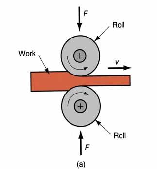
7 Bulk Deformation Rolling Forging Extrusion Drawing
8 Plastic Behavior in Metal Forming Plastic region of stress-strain curve is primary interest because material is plastically deformed In plastic region, metal's behavior is expressed by the flow curve: σ = where K = strength coefficient; and n = strain hardening exponent Stress and strain in flow curve are true stress and true strain K ε n
9 Flow Stress For most metals at room temperature, strength increases when deformed due to strain hardening Flow stress = instantaneous value of stress required to continue deforming the material Yf = Kε n where Y f = flow stress, that is, the yield strength as a function of strain
10 Average Flow Stress Determined by integrating the flow curve equation between zero and the final strain value defining the range of interest _ Y f K = 1 + ε n n _ where Y f = average flow stress; and ε = maximum strain during deformation process
11 Temperature in Metal Forming For any metal, K and n in the flow curve depend on temperature Both strength and strain hardening are reduced at higher temperatures In addition, ductility is increased at higher temperatures Any deformation operation can be accomplished with lower forces and power at elevated temperature Three temperature ranges in metal forming: Cold working Warm working Hot working
12 Cold Working Performed at room temperature or slightly above Many cold forming processes are important mass production operations Minimum or no machining usually required These operations are near net shape or net shape processes
13 Advantages of Cold Forming Better accuracy, closer tolerances Better surface finish Strain hardening increases strength and hardness Grain flow during deformation can cause desirable directional properties in product No heating of work required
14 Disadvantages of Cold Forming Higher forces and power required Surfaces of starting workpiece must be free of scale and dirt Ductility and strain hardening limit the amount of forming that can be done In some operations, metal must be annealed to allow further deformation In other cases, metal is simply not ductile enough to be cold worked
15 Warm Working Performed at temperatures above room temperature but below recrystallization temperature Dividing line between cold working and warm working often expressed in terms of melting point: 0.3T m, where T m = melting point (absolute temperature) for metal
16 Advantages of Warm Working Lower forces and power than in cold working More intricate work geometries possible Need for annealing may be reduced or eliminated
17 Hot Working Deformation at temperatures above recrystallization temperature Recrystallization temperature = about one half of melting point on absolute scale In practice, hot working usually performed somewhat above 0.5T m Metal continues to soften as temperature increases above 0.5T m, enhancing advantage of hot working above this level
18 Advantages of Hot Working Workpart shape can be significantly altered Lower forces and power required Metals that usually fracture in cold working can be hot formed Strength properties of product are generally isotropic No strengthening of part occurs from work hardening Advantageous in cases when part is to be subsequently processed by cold forming
19 Disadvantages of Hot Working Lower dimensional accuracy Higher total energy required (due to the thermal energy to heat the workpiece) Work surface oxidation (scale), poorer surface finish Shorter tool life
20 Strain Rate Sensitivity Theoretically, a metal in hot working behaves like a perfectly plastic material, with strain hardening exponent n = 0 The metal should continue to flow at the same flow stress, once that stress is reached However, an additional phenomenon occurs during deformation, especially at elevated temperatures: Strain rate sensitivity
21 Strain Rate Strain rate in forming is directly related to speed of deformation(speed of Deformation) v Deformation speed v = velocity of the ram or other movement of the equipment Strain rate is defined: ε ε = where = true strain rate; and h = instantaneous height of workpiece being deformed v h
22 Strain Rate Sensitivity Flow stress is a function of temperature At hot working temperatures, flow stress also depends on strain rate As strain rate increases, resistance to deformation increases This effect is known as strain rate sensitivity
23 Strain Rate Sensitivity Log-Log Scale
24 Strain Rate Sensitivity Yf = Cε m where C = strength constant (similar but not equal to strength coefficient in flow curve equation), and m = strain rate sensitivity exponent
25 Strain Rate Sensitivity Effect of temperature on flow stress for a typical metal. The constant C, indicated by the intersection of each plot with the vertical dashed line at strain rate = 1.0, decreases, and m (slope of each plot) increases with increasing temperature
26 Rolling Processes

27 Flat Plate Rolling Deformation process in which work thickness is reduced by compressive forces exerted by two opposing rolls
28 The Rolls The rotating rolls perform two main functions: Pull the work into the gap between them by friction between workpart and rolls Simultaneously squeeze the work to reduce cross section
29 By geometry of work: Types of Rolling Flat rolling - used to reduce thickness of a rectangular cross section Shape rolling - a square cross section is formed into a shape such as an I beam By temperature of work: Hot Rolling most common due to the large amount of deformation required Cold rolling produces finished sheet and plate stock

30 Steel Products by Rolling Mill
31 Side View of Flat Rolling
32 Flat Rolling Draft = amount of thickness reduction d = t t o f where d = draft; t o = starting thickness; and t f = final thickness Reduction = draft expressed as a fraction of starting stock thickness: r where r = reduction = d t o
33 Shape Rolling Work is deformed into a contoured cross section rather than flat (rectangular) Accomplished by passing work through rolls that have the reverse of desired shape Products include: Construction shapes such as I beams, L beams, and U channels Rails for railroad tracks Round and square bars and rods

34 Rolling Mill
35 Rolling Mills Equipment is massive and expensive Rolling mill configurations: Two-high two opposing large diameter rolls Three-high work passes through both directions Four-high backing rolls support smaller work rolls Cluster mill multiple backing rolls on smaller rolls Tandem rolling mill sequence of two-high mills


36 Rolling Mills 2 high 3 high 4 high Cluster mill Tandem rolling mill
37 Thread Rolling Bulk deformation process used to form threads on cylindrical parts by rolling them between two dies Most important commercial process for mass producing bolts and screws Performed by cold working in thread rolling machines Advantages over thread cutting (machining): Higher production rates Better material utilization Stronger threads due to work hardening Better fatigue resistance due to compressive stresses introduced by rolling

38 Thread Rolling with Flat Dies Start of Cycle End of Cycle
39 Ring Rolling Deformation process in which a thick walled ring of smaller diameter is rolled into a thin walled ring of larger diameter As thick walled ring is compressed, deformed metal elongates, causing diameter of ring to be enlarged Hot working process for large rings and cold working process for smaller rings Applications: ball and roller bearing races, steel tires for railroad wheels, and rings for pipes, pressure vessels, and rotating machinery Advantages: material savings, ideal grain orientation, strengthening through cold working

40 Ring Rolling Ring rolling used to reduce the wall thickness and increase the diameter of a ring. Start Completion
41 Forging Processes
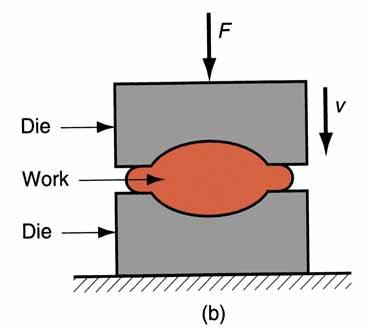
42 Forging Deformation process in which work is compressed between two dies Oldest of the metal forming operations, dating from about 5000 B C Components: engine crankshafts, connecting rods, gears, aircraft structural components, jet engine turbine parts In addition, basic metals industries use forging to establish basic form of large components that are subsequently machined to final shape and size
43 Cold vs. hot forging: Forging Operations Hot or warm forging most common, due to the significant deformation and the need to reduce strength and increase ductility of work metal Cold forging - advantage is increased strength that results from strain hardening Impact vs. press forging: Forge hammer - applies an impact load Forge press - applies gradual pressure
44 Types of Forging Dies Open die forging - work is compressed between two flat dies, allowing metal to flow laterally without constraint Impression die forging - die surfaces contain a cavity or impression that is imparted to workpart, thus constraining metal flow - flash is created Flashless forging - workpart is completely constrained in die and no excess flash is produced


45 Types of Forging Dies Open Die Forging Impression Die Forging Flashless Forging
46 Open Die Forging Compression of workpart with cylindrical cross section between two flat dies Similar to compression test Deformation operation reduces height and increases diameter of work Common names include upsetting or upset forging
47 Open Die Forging Without Friction If no friction occurs between work and die surfaces, then homogeneous deformation occurs, so that radial flow is uniform throughout workpart height and true strain is given by: h ε = ln o h where h o = starting height; and h = height at some point during compression At h = final value h f, true strain is maximum value

48 Open Die Forging Without Friction ε = ln h h0 F = Y A f
49 Open Die Forging With Friction Friction between work and die surfaces constrains lateral flow of work, resulting in barreling effect In hot open-die forging, effect is even more pronounced due to heat transfer at and near die surfaces, which cools the metal and increases its resistance to deformation
50 Open Die Forging With Friction F = KYA f f K f = µ D h
51
52 Open Die Forging
53 Impression Die Forging Compression of workpart by dies with inverse of desired part shape Flash is formed by metal that flows beyond die cavity into small gap between die plates Flash must be later trimmed from part, but it serves an important function during compression: As flash forms, friction resists continued metal flow into gap, constraining material to fill die cavity In hot forging, metal flow is further restricted by cooling against die plates

54 Impression Die Forging
55 Flashless Forging Compression of work in punch and die tooling whose cavity does allow for flash Starting workpart volume must equal die cavity volume within very close tolerance Process control more demanding than impression die forging Best suited to part geometries that are simple and symmetrical Often classified as a precision forging process

56 Flashless Forging
57 Forging Hammers (Drop Hammers) Apply an impact load against workpart - two types: Gravity drop hammers - impact energy from falling weight of a heavy ram Power drop hammers - accelerate the ram by pressurized air or steam Disadvantage: impact energy transmitted through anvil into floor of building Most commonly used for impression-die forging

58 Drop Hammer

59 Drop Hammer
60 Forging Presses Apply gradual pressure to accomplish compression operation - types: Mechanical presses - converts rotation of drive motor into linear motion of ram Hydraulic presses - hydraulic piston actuates ram Screw presses - screw mechanism drives ram
61 Upsetting and Heading Forging process used to form heads on nails, bolts, and similar hardware products More parts produced by upsetting than any other forging operation Performed cold, warm, or hot on machines called headers or formers Wire or bar stock is fed into machine, end is headed, then piece is cut to length For bolts and screws, thread rolling is then used to form threads


62 Upset Forging Operation for Heading
63 Swaging Accomplished by rotating dies that hammer a workpiece radially inward to taper it as the piece is fed into the dies Used to reduce diameter of tube or solid rod stock Mandrel sometimes required to control shape and size of internal diameter of tubular parts

64 Swaging Swaging process to reduce solid rod stock; the dies rotate as they hammer the work In radial forging, the workpiece rotates while the dies remain in a fixed orientation as they hammer the work
65 Trimming Cutting operation to remove flash from workpart in impression die forging Usually done while work is still hot, so a separate trimming press is included at the forging station Trimming can also be done by alternative methods, such as grinding or sawing

66 Trimming Trimming operation (shearing process) to remove the flash after impression die forging
67 Extrusion Processes
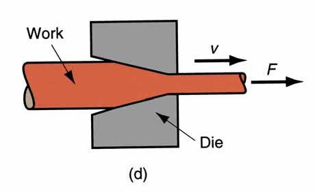
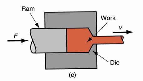
68 Extrusion Compression forming process in which the work metal is forced to flow through a die opening to produce a desired cross sectional shape Process is similar to squeezing toothpaste out of a toothpaste tube In general, extrusion is used to produce long parts of uniform cross-sections Two basic types of extrusion: Direct extrusion - 料 Die Indirect extrusion - Die 料 Die

69 Direct Extrusion As ram approaches die opening, a small portion of billet remains that cannot be forced through die opening This extra portion, called the butt, must be separated from extruded product by cutting it just beyond the die exit Starting billet cross section usually round, but final shape is determined by die opening

70 Direct Extrusion Hollow Semi Hollow

71 Indirect Extrusion Solid Hollow
72 Hot vs. Cold Extrusion Hot extrusion - prior heating of billet to above its recrystallization temperature This reduces strength and increases ductility of the metal, permitting more size reductions and more complex shapes Cold extrusion - generally used to produce discrete parts The term impact extrusion is used to indicate high speed cold extrusion
73 Extrusion Ratio Also called the reduction ratio, it is defined as r x = A A where r x = extrusion ratio; A o = cross-sectional area of the starting billet; and A f = final crosssectional area of the extruded section Applies to both direct and indirect extrusion o f
74 Die Angle and Ram Force
75 Die Angle Low die angle - surface area is large, leading to increased friction at die billet interface Higher friction results in larger ram force Large die angle - more turbulence in metal flow during reduction Turbulence increases ram force required Optimum angle depends on work material, billet temperature, and lubrication

76 A Complex Extruded Cross Section
77 Extrusion Presses Either horizontal or vertical Horizontal more common Extrusion presses - usually hydraulically driven, which is especially suited to semi continuous direct extrusion of long sections Mechanical drives - often used for cold extrusion of individual parts
78 Wire and Bar Drawing
79 Wire and Bar Drawing Cross section of a bar, rod, or wire is reduced by pulling it through a die opening Similar to extrusion except work is pulled through die in drawing (it is pushed through in extrusion) Although drawing applies tensile stress, compression also plays a significant role since metal is squeezed as it passes through die opening

80 Drawing of Bar, Rod, or Wire
81 Area Reduction in Drawing Change in size of work is usually given by area reduction: r = A o A f A o where r = area reduction in drawing; A o = original area of work; and A r = final work
82 Wire Drawing vs. Bar Drawing Difference between bar drawing and wire drawing is stock size Bar drawing - large diameter bar and rod stock Wire drawing - small diameter stock - wire sizes down to 0.03 mm (0.001 in.) are possible Although the mechanics are the same, the methods, equipment, and even terminology are different
83 Drawing Practice and Products Drawing practice: Usually performed as cold working Most frequently used for round cross sections Products: Wire: electrical wire; wire stock for fences, coat hangers, and shopping carts Rod stock for nails, screws, rivets, and springs Bar stock: metal bars for machining, forging, and other processes
84 Bar Drawing Accomplished as a single draft operation the stock is pulled through one die opening Beginning stock has large diameter and is a straight cylinder This necessitates a batch type operation
85 Hydraulically Operated Draw Bench
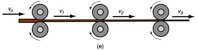
86 Wire Drawing Continuous drawing machines consisting of multiple draw dies (typically 4 to 12) separated by accumulating drums Each drum (capstan) provides proper force to draw wire stock through upstream die Each die provides a small reduction, so desired total reduction is achieved by the series Annealing sometimes required between dies

87 Continuous Drawing of Wire
88 A Draw Die Entry region - funnels lubricant into the die to prevent scoring of work and die Approach - cone shaped region where drawing occurs Bearing surface - determines final stock size Back relief - exit zone - provided with a back relief angle (half angle) of about 30 Die materials: tool steels or cemented carbides

89 Draw Die for Drawing of Round Rod or Wire
90 Sheet Metal Forming
91 Sheet Metalworking Forming and related operations performed on metal sheets, strips, and coils High surface area to volume ratio of starting metal, which distinguishes these from bulk deformation Often called pressworking because presses perform these operations Parts are called stampings Usual tooling: punch and die
92 Sheet Metalworking Bending Drawing Shearing
93 SHEET METALWORKING Cutting Operations Bending Operations Drawing Other Sheet Metal Forming Operations Dies and Presses for Sheet Metal Processes Sheet Metal Operations Not Performed on Presses Bending of Tube Stock
94 Sheet Metalworking Defined Cutting and forming operations performed on relatively thin sheets of metal Thickness of sheet metal = 0.4 mm (1/64 in) to 6 mm (1/4 in) Thickness of plate stock > 6 mm Operations usually performed as cold working
95 Sheet and Plate Metal Products Sheet and plate metal parts for consumer and industrial products such as Automobiles and trucks Airplanes Railway cars and locomotives Farm and construction equipment Small and large appliances Office furniture Computers and office equipment
96 Advantages of Sheet Metal High strength Parts Good dimensional accuracy Good surface finish Relatively low cost For large quantities, economical mass production operations are available
97 Sheet Metalworking 1. Punch and die Terminology Tooling to perform cutting, bending, and drawing 2. Stamping press Machine tool that performs most sheet metal operations 3. Stampings Sheet metal products
98 Three Major Categories of 1. Cutting Sheet Metal Processes Shearing to separate large sheets; or cut part perimeters or make holes in sheets 2. Bending Straining sheet around a straight axis 3. Drawing Forming of sheet into convex or concave shapes
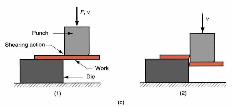
 just before the")
99 Cutting Shearing between two sharp cutting edges Figure 20.1 Shearing of sheet metal between two cutting edges: (1) just before the punch contacts
")
100 Figure 20.1 Shearing of sheet metal between two cutting edges: (2) punch begins to push into work, causing plastic

101 Figure 20.1 Shearing of sheet metal between two cutting edges: (3) punch compresses and
")
102 Figure 20.1 Shearing of sheet metal between two cutting edges: (4) fracture is initiated at the opposing cutting edges which
103 Shearing, Blanking, and Punching Three principal operations in pressworking that cut sheet metal: Shearing Blanking Punching
104 Shearing Sheet metal cutting operation along a straight line between two cutting edges Typically used to cut large sheets into smaller sections for subsequent operations
 side view of the shearing operation (b) front view of power")
105 Figure 20.3 Shearing operation: (a) side view of the shearing operation (b) front view of power shears equipped with inclined upper cutting blade Symbol v indicates motion
106 Blanking and Punching Blanking - sheet metal cutting to separate piece from surrounding stock Cut piece is the desired part, called a blank Punching - sheet metal cutting similar to blanking except cut piece is scrap, called a slug Remaining stock is the desired part
 Blanking and")
107 Figure 20.4 (a) Blanking and (b) punching
108 Clearance in Sheet Metal Cutting Distance between the punch and die Typical values range between 4% and 8% of stock thickness If too small, fracture lines pass each other, causing double burnishing and larger force If too large, metal is pinched between cutting edges and excessive burr results
109 Clearance in Sheet Metal Cutting Recommended clearance can be calculated by: c = at where c = clearance; a = allowance; and t = stock thickness Allowance a is determined according to type of metal
110 Allowance a for Three Sheet Metal Groups Metal group 1100S and 5052S aluminum alloys, all tempers 2024ST and 6061ST aluminum alloys; brass, soft cold rolled steel, soft Cold stainless rolled steel, half hard; stainless steel, half hard and full hard a
111 Punch and Die Sizes for Blanking and Punching For a round blank of diameter D b : Blanking punch diameter = D b 2c Blanking die diameter = D b where c = clearance For a round hole of diameter D h : Hole punch diameter = D h Hole die diameter = D h + 2c where c = clearance

112 Figure 20.6 Die size determines blank size D b ; punch size determines hole size D h.; c = clearance

113 Angular Clearance Purpose: allows slug or blank to drop through die Typical values: 0.25 to 1.5 on each side Figure 20.7 Angular clearance
114 Cutting Forces Important for determining press size (tonnage) F = S t L where S = shear strength of metal; t = stock thickness, and L = length of cut edge
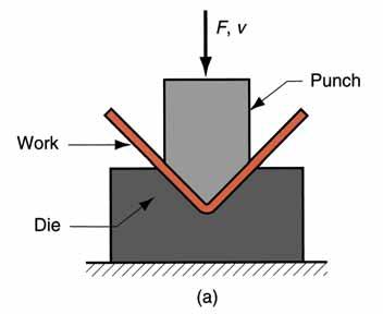
115 Bending Straining sheetmetal around a straight axis to take a permanent bend Figure (a) Bending of sheet metal
116 Metal on inside of neutral plane is compressed, while metal on outside of neutral plane is stretched Figure (b) both compression and tensile elongation of the metal occur in bending
117 Types of Sheetmetal Bending V bending - performed with a V shaped die Edge bending - performed with a wiping die

118 V-Bending For low production Performed on a press brake V-dies are simple and inexpensive Figure (a) V bending

119 Edge Bending For high production Pressure pad required Dies are more complicated and costly Figure (b) edge bending
120 Stretching during Bending If bend radius is small relative to stock thickness, metal tends to stretch during bending Important to estimate amount of stretching, so that final part length = specified dimension Problem: to determine the length of neutral axis of the part before bending
121 Bend Allowance Formula BA = A 2π ( R + Kbat) 360 where BA = bend allowance; A = bend angle; R= bend radius; t = stock thickness; and K ba is factor to estimate stretching If R < 2t, K ba = 0.33 If R 2t, K ba = 0.50
122 Springback in Bending Springback = increase in included angle of bent part relative to included angle of forming tool after tool is removed Reason for springback: When bending pressure is removed, elastic energy remains in bent part, causing it to recover partially toward its original shape
 during bending, the work is forced to")
123 Figure Springback in bending shows itself as a decrease in bend angle and an increase in bend radius: (1) during bending, the work is forced to take the radius R b and included angle A b ' of the bending tool (punch in V bending), (2) after punch is removed, the work springs back
124 Bending Force Maximum bending force estimated as follows: F = K bf TSwt D 2 where F = bending force; TS = tensile strength of sheet metal; w = part width in direction of bend axis; and t = stock thickness. For V- bending, K bf = 1.33; for edge bending, K bf = 0.33
")
125 Figure Die opening dimension D: (a) V die, (b) wiping die
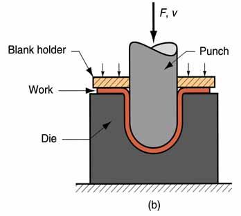
126 Drawing Sheet metal forming to make cup shaped, box shaped, or other complex curved, hollow shaped parts Sheet metal blank is positioned over die cavity and then punch pushes metal into opening Products: beverage cans, ammunition shells, automobile body panels
drawing of a cup shaped part: (1)start of operation")
127 Figure (a)drawing of a cup shaped part: (1)start of operation before punch contacts work (2)near end of stroke
128 Clearance in Drawing Sides of punch and die separated by a clearance c given by: c = 1.1 t where t = stock thickness In other words, clearance = about 10% greater than stock thickness
129 Drawing Ratio DR Most easily defined for cylindrical shape: DR = D D b p where D b = blank diameter; and D p = punch diameter Indicates severity of a given drawing operation Upper limit = 2.0
130 Reduction r Again, defined for cylindrical shape: r = D b D D b p Value of r should be less than 0.50
131 Thickness to Diameter Ratio Thickness of starting blank divided by blank diameter Thickness-to-diameter ratio = t/d b Desirable for t/d b ratio to be greater than 1% As t/d b decreases, tendency for wrinkling increases
132 Blank Size Determination For final dimensions of drawn shape to be correct, starting blank diameter D b must be right Solve for D b by setting starting sheet metal blank volume = final product volume To facilitate calculation, assume negligible thinning of part wall
133 Shapes other than Cylindrical Cups Square or rectangular boxes (as in sinks), Stepped cups, Cones, Cups with spherical rather than flat bases, Irregular curved forms (as in automobile body panels) Each of these shapes presents its own unique technical problems in drawing
134 Other Sheet Metal Forming on Presses Other sheet metal forming operations performed on conventional presses Operations performed with metal tooling Operations performed with flexible rubber tooling
 start of process; (2) during process Note thinning and")
135 Ironing Makes wall thickness of cylindrical cup more uniform Examples: beverage cans and artillery shells Figure Ironing to achieve a more uniform wall thickness in a drawn cup: (1) start of process; (2) during process Note thinning and elongation of walls
 cross section of punch and die configuration during pressing; (b) finished part with embossed")
136 Embossing Used to create indentations in sheet, such as raised (or indented) lettering or strengthening ribs Figure Embossing: (a) cross section of punch and die configuration during pressing; (b) finished part with embossed ribs
 before and (2) after Symbols v and")
137 Guerin Process Figure Guerin process: (1) before and (2) after Symbols v and F indicate motion and applied force
138 Advantages of Guerin Process Low tooling cost Form block can be made of wood, plastic, or other materials that are easy to shape Rubber pad can be used with different form blocks Process attractive in small quantity production
139 Dies for Sheet Metal Processes Most pressworking operations performed with conventional punch and die tooling Custom designed for particular part The term stamping die sometimes used for high production dies

140 Figure Components of a punch and die for a blanking operation
progressiv e die;")
141 Figure (a)progressiv e die; (b)associated strip developme nt

142 Figure Components of a typical mechanical drive stamping press
143 Types of Stamping Press Frame Gap frame configuration of the letter C and often referred to as a C frame Straight sided frame box-like construction for higher tonnage

144 Figure Gap frame press for sheet metalworking (photo courtesy of E. W. Bliss
 and capacity of 11,200 kn (1250 tons); two")
145 Figure Press brake with bed width of 9.15 m (30 ft) and capacity of 11,200 kn (1250 tons); two workers are positioning

146 Figure Several sheet metal parts produced on a turret press, showing variety of hole shapes possible (photo courtesy of Strippet, Inc.)

147 Figure Computer numerical control turret press (photo courtesy of Strippet, Inc.)

148 Figure Straight sided frame press (photo courtesy Greenerd Press & Machine
149 Power and Drive Systems Hydraulic presses - use a large piston and cylinder to drive the ram Longer ram stroke than mechanical types Suited to deep drawing Slower than mechanical drives Mechanical presses convert rotation of motor to linear motion of ram High forces at bottom of stroke Suited to blanking and punching
150 Sheet Metal Operations Not Performed on Presses Stretch forming Roll bending and forming Spinning High energy rate forming processes.
151 Stretch Forming Sheet metal is stretched and simultaneously bent to achieve shape change Figure Stretch forming: (1) start of process; (2) form die is pressed into the work with force F die, causing it to be stretched and bent over the form. F = stretching force
152 Force Required in Stretch Forming F = LtY f where F = stretching force; L = length of sheet in direction perpendicular to stretching; t = instantaneous stock thickness; and Y f = flow stress of work metal Die force F die can be determined by balancing vertical force components

153 Roll Bending Large metal sheets and plates are formed into curved sections using rolls Figure Roll bending
154 Roll Forming Continuous bending process in which opposing rolls produce long sections of formed shapes from coil or strip stock Figure Roll forming of a continuous channel section: (1) straight rolls (2) partial form (3) final form
155 Spinning Metal forming process in which an axially symmetric part is gradually shaped over a rotating mandrel using a rounded tool or roller Three types: 1. Conventional spinning 2. Shear spinning 3. Tube spinning
156 Figure Conventional spinning: (1) setup at start of process; (2) during spinning; and (3) completion of process
157 High Energy Rate Forming (HERF) Processes to form metals using large amounts of energy over a very short time HERF processes include: Explosive forming Electrohydraulic forming Electromagnetic forming
158 Explosive Forming Use of explosive charge to form sheet (or plate) metal into a die cavity Explosive charge causes a shock wave whose energy is transmitted to force part into cavity Applications: large parts, typical of aerospace industry
 setup, (2) explosive is detonated, and")
159 Figure Explosive forming: (1) setup, (2) explosive is detonated, and (3) shock wave forms part and plume escapes water surface
160 Electromagnetic Forming Sheet metal is deformed by mechanical force of an electromagnetic field induced in workpart by an energized coil Presently the most widely used HERF process Applications: tubular parts
 setup in which coil is inserted")
161 Figure Electromagnetic forming: (1) setup in which coil is inserted into tubular workpart surrounded by die; (2) formed part
162 論
163 論 金 狀 金 狀 狀 輪 拉 金 狀 切 度 冷 金
MANUFACTURING TECHNOLOGY
 MANUFACTURING TECHNOLOGY UNIT II Hot & Cold Working - Drawing & Extrusion Drawing Drawing is an operation in which the cross-section of solid rod, wire or tubing is reduced or changed in shape by pulling
Casting. Forming. Sheet metal processing. Powder- and Ceramics Processing. Plastics processing. Cutting. Joining.
 Traditional Manufacturing Processes Casting Forming Sheet metal processing Powder- and Ceramics Processing Plastics processing Cutting Joining Surface treatment FUNDAMENTALS OF METAL FORMING Overview of
Forging. Types of Forging Dies. Open-Die Forging. Outline. Forging. Types of forging Forging analysis Examples
 Forging Outline Forging Types of forging Forging analysis Examples Oldest of te metal forming operations, dating from about 5000 B C Components: engine cranksafts, connecting rods, gears, aircraft structural
Module 3 Selection of Manufacturing Processes. IIT Bombay
 Module 3 Selection of Manufacturing Processes Lecture 3 Design for Bulk Deformation Processes Instructional objectives By the end of this lecture, the students are expected to learn the working principle
Chapter 15 Extrusion and Drawing of Metals
 Introduction Chapter 15 Extrusion and Drawing of Metals Alexandra Schönning, Ph.D. Mechanical Engineering University of North Florida Figures by Manufacturing Engineering and Technology Kalpakijan and
Chapter 14: Metal-Forging Processes and Equipments
 Manufacturing Engineering Technology in SI Units, 6 th Edition Chapter 14: Metal-Forging Processes and Equipments Chapter Outline Introduction Open-die Forging Impression-die and Closed-die Forging Various
ME 4563 ME 4563 ME Introduction to Manufacturing Processes. College of Engineering Arkansas State University.
 Introduction to Manufacturing Processes College of Engineering Arkansas State University 1 Bulk Deformation 2 1 Rolling 3 What is Rolling? A process of reducing the thickness (or changing the cross-section
Design for Forging. Forging processes. Typical characteristics and applications
 Design for Forging Forging processes Forging is a controlled plastic deformation process in which the work material is compressed between two dies using either impact or gradual pressure to form the part.
Metal extrusion. Metal stamping
 Metal extrusion Answer the following questions 1. In which of the following extrusion operation is friction a factor in determining the extrusion force (one best answer): (a) direct extrusion or (b) indirect
Metal Forming Process. Prof.A.Chandrashekhar
 Metal Forming Process Prof.A.Chandrashekhar Introduction Shaping of a component by the application of external forces is known as the metal forming. Metal forming can be described as a process in which
Chapter 14 Forging of Metals
 Introduction Chapter 14 Forging of Metals Alexandra Schönning, Ph.D. Mechanical Engineering University of North Florida Figures by Manufacturing Engineering and Technology Kalpakijan and Schmid What is
Bulk Deformation Forming - Rolling
 1 Bulk Deformation Forming - Rolling Overview - Shaping and Forming Powders Pressing SLS Special Injection Molding Firing/ Sintering 2 Raw Material Molten Material Continuous Casting/Rolling Ingot casting
SHRI GURU GOBIND SINGHJI INSTITUTE OF ENGG & TECHNOLOGY DEPARTMENT OF PRODUCTION ENGINEERING SUBJECT:MECHANICAL WORKING OF METALS EXPERIMENT NO: 3
 SHRI GURU GOBIND SINGHJI INSTITUTE OF ENGG & TECHNOLOGY DEPARTMENT OF PRODUCTION ENGINEERING SUBJECT:MECHANICAL WORKING OF METALS EXPERIMENT NO: 3 AIM: STUDY OF FORGING EQUIPMENT AIM: Study of forging
1. Definitions and classification of Metal forming processes
 1. Definitions and classification of Metal forming processes 1.1 Introduction: Metal forming is a very important manufacturing operation. It enjoys industrial importance among various production operations
Extrusion of complex shapes
 Extrusion of complex shapes 1 Hot extrusion Hot extrusion is the process of forcing a heated billet to flow through a shaped die opening It is used to produce long, strait metal products of constant cross
Mechanical behavior of crystalline materials - Stress Types and Tensile Behaviour
 Mechanical behavior of crystalline materials - Stress Types and Tensile Behaviour 3.1 Introduction Engineering materials are often found to posses good mechanical properties so then they are suitable for
Objectives. This chapter provides fundamental background on processes of drawing of rods, wires and tubes.
 WIRE DRAWING Objectives This chapter provides fundamental background on processes of drawing of rods, wires and tubes. Mathematical approaches for the calculation of drawing load will be introduced. Finally
Types of Strain. Engineering Strain: e = l l o. Shear Strain: γ = a b
 Types of Strain l a g Engineering Strain: l o l o l b e = l l o l o (a) (b) (c) Shear Strain: FIGURE 2.1 Types of strain. (a) Tensile. (b) Compressive. (c) Shear. All deformation processes in manufacturing
MF9223 METAL FORMING PROCESSES UNIT III SHEET METAL FORMING
 MF9223 METAL FORMING PROCESSES UNIT III SHEET METAL FORMING Formability studies Conventional processes H E R F techniques Superplastic forming techniques Hydro forming Stretch forming Water hammer forming
where n is known as strain hardening exponent.
 5.1 Flow stress: Flow stress is the stress required to sustain a certain plastic strain on the material. Flow stress can be determined form simple uniaxial tensile test, homogeneous compression test, plane
Introduction. 1. Outline of fan case ring
 A near-net-shape (NNS) ring-rolling process was developed to reduce the forging weight of a rolled, fan case front, ring made of Ti-6Al-4V. This was achieved by optimizing the ring-rolling process in which
Mechanical behavior of crystalline materials- Comprehensive Behaviour
 Mechanical behavior of crystalline materials- Comprehensive Behaviour In the previous lecture we have considered the behavior of engineering materials under uniaxial tensile loading. In this lecture we
Heinz Tschaetsch Metal Forming Practise
 Heinz Tschaetsch Metal Forming Practise Heinz Tschaetsch Metal Forming Practise Processes Machines Tools Translated by Anne Koth 123 Author: Professor Dr.-Ing. e. h. Heinz Tschaetsch Paul-Gerhardt-Str.
True Stress and True Strain
 True Stress and True Strain For engineering stress ( ) and engineering strain ( ), the original (gauge) dimensions of specimen are employed. However, length and cross-sectional area change in plastic region.
Powder-Metal Processing and Equipment
 Powder-Metal Processing and Equipment Text Reference: Manufacturing Engineering and Technology, Kalpakjian & Schmid, 6/e, 2010 Chapter 17 Powder Metallurgy Metal powders are compacted into desired and
1. Consider the following stress-strain responses of metallic materials:
 TECNOLOGIA MECÂNICA Mestrado em Engenharia de Materiais January 3, 2015 Number: Name: 1. Consider the following stress-strain responses of metallic materials: Y Load Unload Y E Load E Unload Y (1) (2)
A wide range of cold-formable steel grades and aluminium alloys are used as wire materials within a diameter range from 5 mm to 34 mm.
 Cold-Formed Parts 2 ESKA manufactures complex precision cold-formed parts for applications with large and medium quantities. The highly-efficient cold- forming process ensures economic manufacture of near-net-shape
Powder Metallurgy. Powder-Metal Processing and Equipment 11/10/2009
 Powder Metallurgy Powder-Metal Processing and Equipment Metal powders are compacted into desired and often complex shapes and sintered* to form a solid piece * Sinter: To heat without melting Text Reference:
J.I.C. HYDRAULIC TUBING Seamless & Welded Hydraulic Fluid Line 23 Seamless Burst Pressures & Working Pressures 24 Welded Burst Pressures 25
 TABLE OF CONTENTS STEEL & ALLOY ROUND MECHANICAL TUBING Drawn Over Mandrel (DOM) 3-15 Cold Drawn Seamless (CDS) 3-15 Hot Rolled Seamless (HRS) 3-15 Electric Resistance Welded (ERW) 3-15 Seamless 4130/4140
COMPUTER SIMULATION BASED DESIGN AND OPTIMISATION OF DIE FORGING OPERATIONS
 COMPUTER SIMULATION BASED DESIGN AND OPTIMISATION OF DIE FORGING OPERATIONS Dr.S.Shamasundar ProSIM, 21/B. 9 th main Shankara Nagara, Mahalakshmipuram Bangalore-560096 Email: shama@pro-sim.com Web: www.pro-sim.com
Tensile Testing. Objectives
 Laboratory 3 Tensile Testing Objectives Students are required to understand the principle of a uniaxial tensile testing and gain their practices on operating the tensile testing machine to achieve the
STRENGTH OF MATERIALS laboratory manual
 STRENGTH OF MATERIALS laboratory manual By Prof. Shaikh Ibrahim Ismail M.H. Saboo Siddik College of Engineering, MUMBAI TABLE OF CONTENT Sr. No. Title of Experiment page no. 1. Study of Universal Testing
Stamping Basics. Fundamentals & Terminology
 Stamping Basics Fundamentals & Terminology 2 Introduction The Dayton Mission It is the mission of Dayton Progress Corporation to continue furnishing our customers with the highest quality information,
METAL FORMING AND THE FINITE-ELEMENT METHOD SHIRO KOBAYASHI SOO-IK OH TAYLAN ALTAN
 METAL FORMING AND THE FINITE-ELEMENT METHOD SHIRO KOBAYASHI SOO-IK OH TAYLAN ALTAN New York Oxford OXFORD UNIVERSITY PRESS 1989 CONTENTS Symbols, xiii 1. Introduction, 1 1.1 Process Modeling, 1 1.2 The
Solid-State Welding Processes
 Solid-State Welding Processes Text Reference: Manufacturing Engineering and Technology, Kalpakjian & Schmid, 6/e, 2010 Chapter 31 Solid-State State Welding Processes Joining takes place without fusion
CUTTING TOOL TECHNOLOGY
 CUTTING TOOL TECHNOLOGY Tool Life Tool Materials Tool Geometry Cutting Fluids Cutting Tool Technology Two principal aspects: 1. Tool material 2. Tool geometry Three Modes of Tool Failure Fracture failure
GRINDING AND OTHER ABRASIVE PROCESSES
 GRINDING AND OTHER ABRASIVE PROCESSES Grinding Related Abrasive Process Abrasive Machining Material removal by action of hard, abrasive particles usually in the form of a bonded wheel Generally used as
MECHANICS OF MATERIALS
 Lecture Notes: Dr. Hussam A. Mohammed Al- Mussiab Technical College Ferdinand P. Beer, E. Russell Johnston, Jr., and John T. DeWolf Introduction Concept of Stress The main objective of the study of mechanics
Material flow analysis for hot-forming of 20MnCr5 gear wheel blanks
 IDE 2008, Bremen, Germany, September 17 th 19 th, 2008 77 Material flow analysis for hot-forming of 20MnCr5 gear wheel blanks Rüdiger Rentsch Foundation Institute of Materials Science (IWT), Badgasteinerstr.
Numerical Simulation on the Hot Stamping Process of an Automobile Protective Beam
 2016 International Conference on Material Science and Civil Engineering (MSCE 2016) ISBN: 978-1-60595-378-6 Numerical Simulation on the Hot Stamping Process of an Automobile Protective Beam Han-wu LIU
Roll Bonding or Roll Welding
 1 2 3 4 Roll Bonding or Roll Welding The pressure required for welding is applied through a pair of rolls Can be performed hot (Hot Roll Bonding) Surface preparation is important for interfacial bonding
Chapter 19. Forming and Shaping Plastics and Composite Materials
 Chapter 19 Forming and Shaping Plastics and Composite Materials Characteristics of Forming and Shaping Processes for Plastics and Composite Materials Forming and Shaping Processes for Plastics, Elastomers,
3. Mechanical Properties of Materials
 3. Mechanical Properties of Materials 3.1 Stress-Strain Relationships 3.2 Hardness 3.3 Effect of Temperature on Properties 3.4 Fluid Properties 3.5 Viscoelastic Properties Importance of Mechanical Properties
PUNCH FORCE BEHAVIOR DURING MICRO V-BENDING PROCESS OF THE COPPER FOIL
 International Journal of Technology (017) 7: 1314-130 ISSN 086-9614 IJTech 017 PUNCH FORCE BEHAVIOR DURING MICRO V-BENDING PROCESS OF THE COPPER FOIL Gandjar Kiswanto 1*, Aida Mahmudah 1,, Dedi Priadi
Solutions in Steel Innovative Technologies for Smart Solutions
 Solutions in Steel Innovative Technologies for Smart Solutions Company Montanstahl is a dynamic family-owned company active in the production and supply of high quality special steel shapes. Established
1060, 1100, 3003, 3105, 5052, 5083, 5754, 6061 etc.
 Product Name Picture Alloy Temper Thickness Width 5 bars Tread Plate /Aluminu m Checker Plate 1060, 1100, 3003, 3105, 5052, 5083, 5754, 6061 etc. H12, H14, H16, H18, H22, H24, H26, H32, H34, H36, H38,
The strength of a material depends on its ability to sustain a load without undue deformation or failure.
 TENSION TEST The strength of a material depends on its ability to sustain a load without undue deformation or failure. This strength is inherent in the material itself and must be determined by experiment.
EXPERIMENTAL EVALUATION OF RBD PALM OLEIN AS LUBRICANT IN COLD METAL FORMING
 Jurnal Mekanikal December 2010, No. 31, 1-10 EXPERIMENTAL EVALUATION OF RBD PALM OLEIN AS LUBRICANT IN COLD METAL FORMING S. Syahrullail *1, S. Kamitani 2 and K. Nakanishi 2 1 Faculty of Mechanical Engineering,
AISI D2 Cold work tool steel
 T OOL STEEL FACTS AISI D2 Cold work tool steel Great Tooling Starts Here! This information is based on our present state of knowledge and is intended to provide general notes on our products and their
Study of Roll Forming Bending in Different Temperature
 International Journal of Materials Science and Applications 2016; 5(3): 129-135 http://www.sciencepublishinggroup.com/j/ijmsa doi: 10.11648/j.ijmsa.20160503.13 ISSN: 2327-2635 (Print); ISSN: 2327-2643
AISI A2 Cold work tool steel
 T OOL STEEL FACTS AISI A2 Cold work tool steel Great Tooling Starts Here! General AISI A2 is an air- or oil hardening chromiummolybdenum-vanadium alloyed tool steel characterized by: Good machinability
CUTTING FORCE AND SNAP- THROUGH REDUCTION PRINCIPLES AND TECHNIQUES
 CUTTING FORCE AND SNAP- THROUGH REDUCTION PRINCIPLES AND TECHNIQUES The peak pressure required to cut through material can be reduced by grinding one or more shear angle(s) on the punch or die. If the
Resource Guide. Section 3: Ductile Iron
 Resource Guide Section 3: Ductile Iron Section 3 Ductile Iron Description of Grades... 3-3 65-45-12 Ferritic... 3-4 80-55-06 Partially Pearlitic... 3-6 100-70-02 Pearlitic... 3-8 4512 HRDS Heat Resistant...
Chapter 16. Sheet-Metal Forming Processes. Sheet-Metal Parts. Shearing with a Punch and Die. Shearing. Die-Cutting Operations
 Chapter 16 Sheet-Metal Forming Processes Sheet-Metal Parts (a) (b) Figure 16.1 Examples of sheet-metal parts. (a) Die-formed and cut stamped parts. (b) Parts produced by spinning. Source: (a) Courtesy
MACHINES DESIGN SSC-JE STAFF SELECTION COMMISSION MECHANICAL ENGINEERING STUDY MATERIAL MACHINES DESIGN
 1 SSC-JE STAFF SELECTION COMMISSION MECHANICAL ENGINEERING STUDY MATERIAL C O N T E N T 2 1. MACHINE DESIGN 03-21 2. FLEXIBLE MECHANICAL ELEMENTS. 22-34 3. JOURNAL BEARINGS... 35-65 4. CLUTCH AND BRAKES.
A REVIEW ON COST OPTIMIZATION OF POWER PRESS BY ANALYSIS OF C-FRAME USING SOLID WORKS
 A REVIEW ON COST OPTIMIZATION OF POWER PRESS BY ANALYSIS OF C-FRAME USING SOLID WORKS 1 Mustafa Telwala, 2 Anand Parikh, 3 Vaja Hitesh, 4 HardikbhaiDabhi, 5 Rajdipsinh. G. Vaghela, 6 Hardik N. Chauhan
Processing of Metal Powders
 Chapter 17 Processing of Metal Powders QUALITATIVE PROBLEMS 17.15 Why is there density variation in the compacting of powders? How is it reduced? The main reason for density variation in compacting of
1) Fracture, ductile and brittle fracture 2) Fracture mechanics
 Fracture, ductile and brittle fracture 2) Fracture mechanics") Module-08 Failure 1) Fracture, ductile and brittle fracture 2) Fracture mechanics Contents 3) Impact fracture, ductile-to-brittle transition 4) Fatigue, crack initiation and propagation, crack propagation
Module-08 Failure 1) Fracture, ductile and brittle fracture 2) Fracture mechanics Contents 3) Impact fracture, ductile-to-brittle transition 4) Fatigue, crack initiation and propagation, crack propagation
Introduction to Structural Analysis TYPES OF STRUCTURES LOADS AND
 AND Introduction to Structural Analysis TYPES OF STRUCTURES LOADS INTRODUCTION What is the role of structural analysis in structural engineering projects? Structural engineering is the science and art
REVISED PAGES IMPORTANT TERMS AND CONCEPTS REFERENCES QUESTIONS AND PROBLEMS. 166 Chapter 6 / Mechanical Properties of Metals
 1496T_c06_131-173 11/16/05 17:06 Page 166 166 Chapter 6 / Mechanical Properties of Metals IMPORTANT TERMS AND CONCEPTS Anelasticity Design stress Ductility Elastic deformation Elastic recovery Engineering
APN029. The SER2 Universal platform for material testing. A.Franck TA Instruments Germany
 APN029 The SER2 Universal platform for material testing A.Franck TA Instruments Germany Keywords: Elongation viscosity, Hencky rate, SER, friction testing INTRODUCTION The roots of extensional rheometry
Hydraulic crimping: application to the assembly of tubular components
 Journal of Materials Processing Technology 146 (2004) 44 51 Hydraulic crimping: application to the assembly of tubular components Manas Shirgaokar a, Gracious Ngaile a, Taylan Altan a,, Jang-Horng Yu b,
Ch 14 Single-Station Manufacturing Cells
 Ch 14 Single-Station Manufacturing Cells Sections: 1. Single-Station Manned Workstations 2. Single-Station Automated Cells 3. Applications of Single-Station Cells 4. Analysis of Single-Station Cells Classification
COPPER PRODUCTS. 145 COPPER PRODUCTS Half Hard Tellurium Rounds
 COPPER PRODUCTS 110 COPPER PRODUCTS Rounds... 12-2 Squares... 12-2 Flats - Square Edge...12-3 thru12-4 Flats - Full Round Edge (FRE)... 12-5 Cold Rolled Sheet... 12-6 110 Quarter Hard Copper Sheet... 12-6
2. LITERATURE REVIEW
 2. LITERATURE REVIEW For defining the goal of research, in this section a brief overview of Sheet metal forming, Bulk metal forming, Incremental forming process, FEM analysis, System Design approach, numerical
METALWORKING DEFORMATION YOUR ADVANTAGE IN AN INDUSTRIAL WORLD
 METALWORKING DEFORMATION YOUR ADVANTAGE IN AN INDUSTRIAL WORLD A CHOICE TO SUIT ALL NEEDS We offer you an innovative, comprehensive and high performing metal forming product range under the Castrol Iloform
Extrusion. Key Issues to Address. Lecture 2. Process. Process Variants. Process Analysis. Problem Solving
 Extrusion Lecture 2 Chapter 4 Key Issues to Address Process Process Variants Process Analysis Problem Solving S.V. Atre 1 Extrusion Material is forced to flow through a die orifice to provide long continuous
MILD STEEL SHEET METAL FORMING USING ABAQUS SOFTWARE: INFLUENCE OF DRAWBEADS IN MINIMIZE SPRINGBACK
 MILD STEEL SHEET METAL FORMING USING ABAQUS SOFTWARE: INFLUENCE OF DRAWBEADS IN MINIMIZE SPRINGBACK Nor Assikin Khamis 1, Suziyani Md Zin 1 and Abdul Rahim Bahari 2 1 Department of Mechanical Engineering,
EXPERIMENTAL INVESTIGATION ON COOLING RATE FOR CENTRIFUGAL CASTING Kirti Kanaujiya, Yugesh Mani Tiwari Department of Mechanical Engineering
 ISSN 2320-9135 1 International Journal of Advance Research, IJOAR.org Volume 3, Issue 9, September 2015, Online: ISSN 2320-9135 EXPERIMENTAL INVESTIGATION ON COOLING RATE FOR CENTRIFUGAL CASTING Kirti
Aluminum Extrusion Alloy Guides
 Aluminum Extrusion Alloy Guides There are two extrusion processes, direct and indirect. With direct, the ingot moves relative to the container wall; with indirect, the die moves. Under pressure, the ingot
CRIMP TOOLING WHERE FORM MEETS FUNCTION
 CRIMP TOOLING WHERE FORM MEETS FUNCTION The cost of quality can be expensive Introduction Quality, cost, and throughput are associated with specific measurements and linked to process variables. Crimp
Crimp Tooling Where Form Meets Function
 Crimp Tooling Where Form Meets Function Quality, cost, and throughput are key attributes for any production process. The crimp termination process is no exception. Many variables contribute to the results.
Mechanical Properties of Materials
 INTRODUCTION Mechanical Properties of Materials Many materials, when in service, are subjected to forces or loads, it is necessary to know the characteristics of the material and to design the member from
MECHANICAL PROPERTIES
 MECHANICAL PROPERTIES Mechanical Properties: In the course of operation or use, all the articles and structures are subjected to the action of external forces, which create stresses that inevitably cause
The following tubing can be supplied from stock, on futures or on a periodic release program which we can design to fit your needs.
 The following tubing can be supplied from stock, on futures or on a periodic release program which we can design to fit your needs. I. Seamless Copper and Brass Tubing - as per ASTM and military standards,
FRAUNHOFER INSTITUTE FOR MACHINE TOOLS AND FORMING TECHNOLOGY IWU SIMULATION IN FORMING TECHNOLOGY
 FRAUNHOFER INSTITUTE FOR MACHINE TOOLS AND FORMING TECHNOLOGY IWU SIMULATION IN FORMING TECHNOLOGY 1 SIMULATION IN SHEET METAL FORMING Simulation is an essential part of the development chain, especially
ERC/NSM Activities. Research for Industry and Government
 / Activities Research for Industry and Government Stamping Hydroforming Machining Forging / Activities in Tube Hydroforming 1. Materials Determination of material flow stress data for tubular materials
FE Review Mechanics of Materials
 1 2 3 4 5 6 7 8 9 10 11 12 13 14 15 16 17 18 19 20 21 22 23 24 25 26 27 28 29 1. T he element is subjected to the plane stress condition shown. a-x = - 140 M Pa a- y = 205 M Pa Txy = 100 M Pa What is t
Breaking Strength and Elongation of Pressure Sensitive Tapes
 Harmonized International Standard Breaking Strength and Elongation of Pressure Sensitive Tapes Call Letters PSTC-131 Date of Issuance 09/55 Revised 04/66 Revised 11/70 Revised 08/85 Revised 08/89 Revised
Stainless Steel & Stainless Steel Fasteners Chemical, Physical and Mechanical Properties
 Stainless Steel & Stainless Steel Fasteners Chemical, Physical and Mechanical Properties Stainless steel describes a family of steels highly resistant to tarnishing and rusting that contain at least two
NEW DEVELOPMENTS IN SHEET METAL FORMING
 NEW DEVELOPMENTS IN SHEET METAL FORMING Taylan Altan Center for Precision Forming - CPF The Ohio State University Columbus, OH https://ercnsm.osu.edu / https://cpf.osu.edu Overview of CPF activities November
CHAPTER 3 OUTLINE PROPERTIES OF MATERIALS PART 1
 CHAPTER 3 PROPERTIES OF MATERIALS PART 1 30 July 2007 1 OUTLINE 3.1 Mechanical Properties 3.1.1 Definition 3.1.2 Factors Affecting Mechanical Properties 3.1.3 Kinds of Mechanical Properties 3.1.4 Stress
Application of The Finite Volume Method to Upset Forging of Cylinders. Introduction. Nomenclature. Arjaan J. Buijk
 Arjaan J. Buijk Manufacturing Division MSC.Software Corporation arjaan.buijk@mscsoftware.com Presented at: Forging Fair 2000 April 13, 2000 Columbus, Ohio Application of The Finite Volume Method to Upset
3. MECHANICAL PROPERTIES OF STRUCTURAL MATERIALS
 3. MECHANICAL PROPERTIES OF STRUCTURAL MATERIALS Igor Kokcharov 3.1 TENSION TEST The tension test is the most widely used mechanical test. Principal mechanical properties are obtained from the test. There
ArcelorMittal Dofasco Scrap Specifications and Requirements
 ArcelorMittal Dofasco Scrap Specifications and Requirements Revision date: January 2017 Table of Contents Type of Scrap: Auto Cast (Brake Rotors and Drums)... 2 Type of Scrap: Bushelling... 4 Type of Scrap:
INTRODUCTION AND OVERVIEW OF MANUFACTURING. Manufacturing is Important. Manufacturing - Technologically Important
 INTRODUCTION AND OVERVIEW OF MANUFACTURING 1. What is Manufacturing? 2. Materials in Manufacturing 3. Manufacturing Processes 4. Production Systems 5. Organization of the Book Manufacturing is Important
Pipe & Tube Nashville Optimizing operations through continuous improvement. The metallurgical benefits of cold rolling high performance alloys
 Pipe & Tube Nashville 2012 Optimizing operations through continuous improvement The metallurgical benefits of cold rolling high performance alloys instead of cold drawing to manufacture thin wall tubing
ENGINEERING MATERIAL 100
 Department of Applied Chemistry Division of Science and Engineering SCHOOL OF ENGINEERING ENGINEERING MATERIAL 100 Experiments 4 and 6 Mechanical Testing and Applications of Non-Metals Name: Yasmin Ousam
Mechanical Properties of Metals. Goals of this unit
 Mechanical Properties of Metals Instructor: Joshua U. Otaigbe Iowa State University Goals of this unit Quick survey of important metal systems Detailed coverage of basic mechanical properties, especially
ANSWER ONLY FIVE QUESTIONS
 Ministry of Higher Education & Scientific Research, Baghdad-Iraq University Of Technology Department of Materials Engineering وزارة التعليم العالي والبحث العلمي بغاد - العراق الجامعت التكنولوجيت قسم هندست
Metal Forming By Sheet Metal Spinning Enhancement of Mechanical Properties and Parameter of Metal Spinning
 Metal Forming By Sheet Metal Spinning Enhancement of Mechanical Properties and Parameter of Metal Spinning 1 Mahesh shinde, 2 Suresh Jadhav, 3 Kailas Gurav 1 PG Scholar, 2 Assistant Professor 3 M.E Design
Types of Metal Alloys
 Types of Metal Alloys Metal alloys Ferrous Nonferrous Steels Cast iron 257 Uses low carbon
CAE Analysis of Crankshaft for Testing Dynamic Loads for Reducing Cost & Weight
 2303-2307 CAE Analysis of Crankshaft for Testing Dynamic Loads for Reducing Cost & Weight Salim Ahmed, Tasmeem Ahmad Khan Abstract This study was conducted on a single cylinder four stroke cycle engine.
Lecture 9 - Manufacturing in Engineering
 Introduction Dr. Carolyn Skurla Speaking Slide 2 Process Selection Choice depends on: The material from which the component is to be made. The size, shape, and dimension tolerances for the component. The
PTFE BELLOWS POLY FLUORO LTD. POLY FLUORO LTD.260A. Bommasandra Industrial Area, Hosur Road, Bangalore TECHNICAL SPECIFICATION
 PTFE BELLOWS TECHNICAL SPECIFICATION 1. MATERIALS 1.1 PTFE Only virgin (not reprocessed) PTFE conforming to ASTM D 1457, type III, IV or V shall be used for the production of bellows; the PTFE raw material
Theoretical study on Cold Open Die Forging Process Optimization for Multipass Workability
 Theoretical study on Cold Open Die Forging Process Optimization for Multipass Workability Ajitkumar Gaikwad 1-a, Shreyas Kirwai 1, Provat Koley 2, Dr. G. Balachandran 3 and Dr. Rajkumar Singh 1 1 Kalyani
Effect of Sheet Thickness and Type of Alloys on the Springback Phenomenon for Cylindrical Die
 AMERICAN JOURNAL OF SCIENTIFIC AND INDUSTRIAL RESEARCH 01, Science Huβ, http://www.scihub.org/ajsir ISSN: 153-69X, doi:10.551/ajsir.01.3.6.80.86 Effect of Sheet Thickness and Type of Alloys on the Springback
A STUDY OF FINE BLANKING PROCESS BY FEM SIMULATION. G. Fang, P. Zeng
 Key Engineering Materials Vols. 261-263 (2004) pp 603-608 Online available since 2004/Apr/15 at www.scientific.net (2004) Trans Tech Publications, Switzerland doi:10.4028/www.scientific.net/kem.261-263.603
1. 3 Extrusion molding
 1. 3 Extrusion molding 9 Extrusion is a widely used technique, both in the field of traditional and technical ceramics. This method allows the continuous manufacture of products with a constant cross-
THE IMPORTANCE OF FRICTION STIR WELDING TOOL
 Production Processes and Systems, vol. 6. (2013) No. 1., pp. 25-34. THE IMPORTANCE OF FRICTION STIR WELDING TOOL Ákos Meilinger, Imre Török University of Miskolc, Department of Mechanical Technology Abstract