GEOSYNTHETICS ENGINEERING: IN THEORY AND PRACTICE
|
|
|
- Henry Stephens
- 6 years ago
- Views:
Transcription
1
2 GEOSYNTHETICS ENGINEERING: IN THEORY AND PRACTICE Prof. J. N. Mandal Department of civil enineerin, IIT Bombay, Powai, Mumbai , India. Tel

3 Module - 3 LECTURE- 13 Geosynthetic properties and test methods
4 RECAP of previous lecture.. Pullout or Anchorae resistance Tensile behavior of Geomembranes Tear resistance of Geomembranes Seam in shear and seam in peel test Hydraulic properties (Continue ) Porosity AOS POA
5 Permittivity or cross plane permeability (ASTM D4491 and ISO 11058): Permittivity Main function of eosynthetic is filtration when water flows perpendicular to the eosynthetic
6 From Darcy s equation: q k n.i.a k n. h t. A k t n q h.a So, Permittivity = k t n q h.a Ψ = Permittivity (sec -1 ) q = Flow rate (m 3 /sec), K n = Hydraulic conductivity (Normal to eosynthetic) (m/s), A = Area of eosynthetic = L x W (m 2 ), h = Head lost (m), and t = Thickness of eosynthetic (m).
7 At different hydraulic radients, the flow rate (q) will be different. The slope of the q/a vs. h curve at the oriin ives the permittivity.
8 Permeability test Constant head test Fallin head test Constant Head permeability test Let, total stored water at time t = Q (m 3 ), Flow rate (q) can be determined as, q = Q/ t (m 3 / sec) Now, Darcy s equation is used to determine the permittivity.
9 Fallin head permittivity test
10 From fallin head test the permittivity can be expressed as, a 2.3 A. t lo 10 h h i f Ψ = permittivity (sec -1 ) a = Area of stand pipe (m 2 ), A = Area of eosynthetics (m 2 ) h i = Initial head at time t 0, h f = Final head at time t f, and t = t f - t o = Chane in time (sec)

11 Transmissivity or in - plane permeability (ASTM D4716 and ISO 12958): Major function of eosynthetic is drainae when water flows alon the plane of eosynthetic under applied load. The test is conducted under a constant head.
12 From Darcy s equation, we can derive the expression for transmissivity, q k p.i.a k p.i.( w. t ) k p.t w q x i Transmissivity (θ) = k p.t q w x i = transmissivity of eosynthetic (m 2 /sec) q = flow rate (m 3 /sec), k p = hydraulic conductivity (in-plane of eosynthetic) (m/sec), i = hydraulic radient = (h/l ), h = head loss (m), L = lenth of eosynthetics (m), and w = width of eosynthetics (m) t = thickness of eosynthetic (m)

13 At different hydraulic radients, the flow rate (q) will be different. The slope of q/w vs. i curve at the oriin ives the permittivity. Transmissivity test Full lenth in-plane flow Radial in-plane flow


14 Full lenth in-plane flow
15 Example: Lenth of the sample (L ) = 200 mm, width of the sample (w ) = 100 mm, thickness of the sample = 0.5 mm, flow rate (q) = 1 x 10⁻⁶ m 3 /sec, head loss = 10 cm. Determine transmissivity and in-plane coefficient of permeability of the eotextile. Solution: k p.t q w x i w q x h L 100 x x m x10 10 x10 x 200 x10 / sec t 2x10 0.5x10 5 k p m / sec
16 Radial in-plane flow
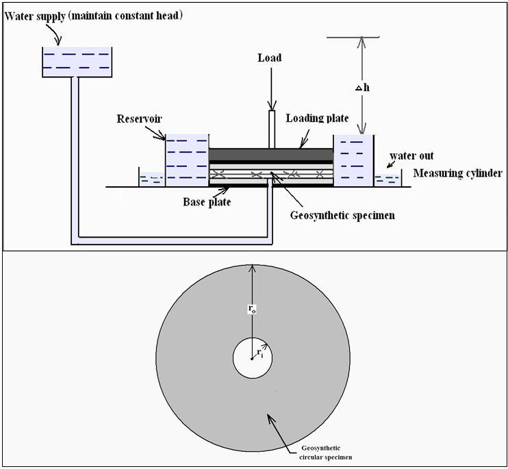
17
18 Accordin to Darcy s law, q = k p. i. A q k p dh dr (2rt ) q k p t (2)r dh dr q dr r 2k p t dh q ln( r r o i ) 2 k p t h k p t q 2h ln( r r o i ) = transmissivity of eosynthetic (m 2 /sec or m 3 / sec-m) r o = outer radius of eosynthetic sample, and r i = inner radius of eosynthetic sample, Δh = the constant head

19 Transmissivity of jute eotextile specimens Transmissivity increases with the increase in the mass per unit area. Transmissivity decreases under hih normal pressure as well as arrives at a constant value after approximately 250 kpa normal pressure. Beyond this pressure, the yarns become dense and too much tiht to carry the water.
20 Endurance properties

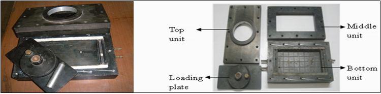
21 Abrasion test or Abrasion resistance (ASTM D4886 and ISO 13427) Schematic of abrasion test Geotextile specimen is disk-shaped. Inner diameter = 60 mm outer diameter = 90 mm The sample is placed on a rubber platform. It is rotated up to 1000 cycles under a fixed abrasion wheel to abrade the eotextile.
22 Two abraded eotextile specimens are cut and tensile strenth test is conducted. Take the averae value. Also determine the tensile strenth of non-abraded eotextile. Strenth retained after abrasion Tensile strenth Tensile strenth of of abraded eotextile non - abraded eotextile x 100 %

23 Ultraviolet (sunliht) deradation (ASTM D4355, ASTM D5208, ASTM D5970) Device for ultraviolet deradation At least five samples are tested for the UV test on both machine and crossmachine directions. Geosynthetics should be kept at site below 32 C. Specimens are exposed to ultraviolet exposure in a xenonarc device at 0, 150, 300 and 500 hr. It consists of 120 min cycles: liht only (90 min) and then water spray and liht (30 min).
24 Firstly, tensile strenth of the specimens without UV exposure is determined in both machine and cross-machine directions. After UV tests, cut strip or ravel strip tensile tests are carried on the exposed specimens. It will show the deterioration of the exposed samples. For polypropylene and polyethylene eorid minimum 70% strenth should be retained after 500 hour (ASTM D4355). For polyester eorid minimum 50% strenth should be retained after 500 hour (ASTM D 4355).

.")
25 Gradient ratio (cloin) test (CW and ASTM D5101) Gradient ratio tests are conducted on soils havin permeability more than about 10-5 m/s. It is suitable for sandy and silty soils (K 10-7 m/sec). Photoraphic view of radient ratio test
26 P 1 Flow P 3 P 5 P 6 P 4 P h 1 =(p 3 +p 4 )/ 2 h 2 =(p 5 +p 6 )/ 2 Z 2 3 SOIL 4 Z 1 1 Geotextile 2 1 To 6 Pizometer Number Z 1 = 25 mm Z 2 = 50 mm h 1 /z 1 Gradient Ratio = h2 /z 2
27 Gradient ratio (GR) = (h 1 /z 1 )/ (h 2 /z 2 ) h 1 = head chane (mm) from the bottom of the eotextile to 25 mm of soil above the eotextile, z 1 = eotextile thickness (mm) plus 25 mm of soil, h 2 = Head chane (mm) from 25 mm soil above eotextile to 50 mm soil above the previous 25 mm z 2 = 50 mm of soil. The acceptable criterion for radient ratio (GR): GR < 1 (Pipin) GR > 1 (Cloin) GR > 3 (Severe cloin) GR = 1 (Stable)

28 Hydraulic conductivity ratio (HCR) (cloin) test on soil-eotextile system (ASTM D 5567) For soils with permeability less than 10-5 conductivity ratio tests are conducted. m/s, hydraulic
29 HCR test is conducted in three staes: First stae is to saturate the sample. Second stae is to carry out primary consolidation of the sample Third stae is to initialize the flow throuh marine clayeotextile system The test is terminated when hydraulic conductivity of the system stabilizes. HCR k k s so k s = hydraulic conductivity of the soileotextile system at any time k so = initial hydraulic conductivity measured at the outset of the permeation phase
30 Test method and Procedure The marine clay-eotextile filter system compatibility under effective stress condition was carried out by conductin Hydraulic Conductivity Ratio (HCR) tests as specified by ASTM D5567. The test method requires placin of the soil and eotextile in a flexible-wall permeameter and the desired effective stress and hydraulic radient are controlled in the system. Size of soil sample: cylindrical remoulded marine clay sample of 75 mm diameter and 50 mm heiht at water content of 60 %.
31 Schematic diaram of hydraulic conductivity ratio (HCR) test equipment durin permeation test stae.
32 Test carried out in three staes: 1. Saturation of soil sample: Done by increasin the cell and back pressure radually till the Skempton s B value of 0.98 was achieved at the cell pressure of 227 kpa and back pressure of 220 kpa. 2. Primary consolidation of soil: Carried out at 50 kpa effective stress. The cell pressure was maintained at 250 kpa and back pressure at 200 kpa. It took about 5 days for the completion of primary consolidation of soil. 3. Permeation of soil eotextile filter system: Carried out at hydraulic radient = 10 and soil effective stress = 50 kpa till the flow was stabilized.
33 Hydraulic Conductivity Ratio (HCR) and pore volume are calculated from the test. Where, HCR k k s so k s = hydraulic conductivity of the soil- eotextile system at any time = (Q/A. i) k so = initial hydraulic conductivity measured at the outset of the permeation phase of the test Q = quantity of water flow for the iven time interval, t A = cross-section area of soil sample = cm 2 i = hydraulic radient alon the system = 10
34 Pore volume flow (V pq ): V pq V V q p V q = cumulative volume of flow that has passed throuh the sample at any iven time V p = pore volume of soil sample = n V n = porosity of soil sample at the end of consolidation stae V = initial volume of soil sample = 221 cm 3 /day
35 For Marine clay - woven jute filter system, n e (1 c e c ) e c e o (1 e o V ) V 1.7 Therefore, n 1.7 (1 1.7) 0.63 e o = initial void ratio of soil sample = 2.11 e c = void ratio at the end of consolidation stae ΔV = soil volume chane at the end of consolidation stae = 28.5 cm 3 V = initial volume of soil sample = 221 cm 3 /day
36 For Marine clay - woven jute filter system, k so = 3.01 m/sec V p = pore volume of soil sample = n V = 0.63 x 221 = cm 3 /day For Marine clay - polypropylene filter system, k so = 3.20 m /sec V p = 142 cm 3 /day k so = initial hydraulic conductivity measured at the outset of the permeation phase of the test
37 Table HCR test results. Marine clay - woven jute filter system Marine clay - polypropylene filter system Time (days) Ks at any iven time x10-9 (m/s) HCR Vq (cm 3 /day) Vpq (cm 3 /day) Ks at any iven time x10-9 (m/s) HCR Vq (cm 3 /day) Vpq (cm 3 /day)
38 Graph of hydraulic conductivity of marine clay-eotextile filter system versus time -Both the systems reached stable flow condition. The hydraulic conductivity in marine clay-woven jute filter system reached stable flow condition after 17 days of initialization of flow throuh the system whereas, Marine clay-polypropylene filter system reached stable flow condition after 13 days.
39 Graph of hydraulic conductivity of marine clay-eotextile filter system versus time
40 Hydraulic conductivity ratio aainst pore volume flow The reduction of hydraulic conductivity ratio in marine claywoven jute filter system was 0.25 and in marine clay polypropylene filter system was flow
, IIT,")
41 Test samples after the test (a) marine clay (b) woven jute eotextile and (c) environmental scannin electron Microscope imae of woven jute eotextile showin clay at the surface (Sophisticated analytical instrument facility (SAIF), IIT, Bombay).
42 Conclusions: The hydraulic conductivity in marine clay-woven jute filter system reached stable flow condition after 17 days of initialization of flow throuh the system whereas marine clay-polypropylene filter system, reached stable flow condition after 13 days. For the iven soil and hydraulic condition, the hydraulic conductivity ratio in marine clay-woven jute filter system reduced to 0.25 and in marine clay polypropylene filter system by 0.28.
43 Marine clay-woven jute filter system has filtration compatibility similar to marine clay polypropylene filter system for the iven hydraulic and soil condition. Visibly no sinificant loss of clay fraction was observed in both the systems.
44 Proper selection of jute eotextile filter plays sinificant role in makin of natural PVDs. Basic requirements of eotextile filter are Ability to retain soil Adequate permeability Resistance to cloin
45 Please let us hear from you Any question?


46 Prof. J. N. Mandal Department of civil enineerin, IIT Bombay, Powai, Mumbai , India. Tel
GEOSYNTHETICS ENGINEERING: IN THEORY AND PRACTICE
 GEOSYNTHETICS ENGINEERING: IN THEORY AND PRACTICE Prof. J. N. Mandal Department of civil engineering, IIT Bombay, Powai, Mumbai 400076, India. Tel.022-25767328 email: cejnm@civil.iitb.ac.in Module - 4
GEOSYNTHETICS ENGINEERING: IN THEORY AND PRACTICE
 GEOSYNTHETICS ENGINEERING: IN THEORY AND PRACTICE Prof. J. N. Mandal Department of civil engineering, IIT Bombay, Powai, Mumbai 400076, India. Tel.022-25767328 email: cejnm@civil.iitb.ac.in Module - 9
Geosynthetics. continued. Prof K. Rajagopal. IIT Madras, Chennai
 Testing of Geosynthetics continued Prof K. Rajagopal Department of Civil Engineering IIT Madras, Chennai e-mail: gopalkr@iitm.ac.inac in Recap Earlier lectures have discussed the testing for the following
Subject Index ASTM D , 28, 57, 63, 67, 83-86, 98, 111, ASTM D , 57
 STP952-EB/JUI. 1987 Subject Index Abrasion resistance, 120, 168-169 Apparent opening size, 7, 21, 29-30, 172-173 defined, 30 versus equivalent opening size, 9-12 Apparent slope height, 96 Approved list,
STANDARDIZATION IN GEOTECH SECTOR V.K.PATIL
 STANDARDIZATION IN GEOTECH SECTOR V.K.PATIL BOMBAY TEXTILE RESEARCH ASSOCIATION L.B.S.MARG, GHATKOPAR (W),MUMBAI-400086. WEB : btraindia.com e-mail : btra@vsnl.com What are Standards? Standards are published
GRI-GC16 Standard Specification for Prefabricated Vertical Drains (PVDs)
") GRI-GC16 Standard Specification for Prefabricated Vertical Drains (PVDs) also called wick drains, or strip drains usually deployed vertically, but other orientations are sometimes used provides for rapid
GRI-GC16 Standard Specification for Prefabricated Vertical Drains (PVDs) also called wick drains, or strip drains usually deployed vertically, but other orientations are sometimes used provides for rapid
GEOSYNTHETICS ENGINEERING: IN THEORY AND PRACTICE
 GEOSYNTHETICS ENGINEERING: IN THEORY AND PRACTICE Prof. J. N. Mandal Department of civil engineering, IIT Bombay, Powai, Mumbai 400076, India. Tel.022-25767328 email: cejnm@civil.iitb.ac.in Module-5 LECTURE-
GEOSYNTHETICS ENGINEERING: IN THEORY AND PRACTICE
 GEOSYNTHETICS ENGINEERING: IN THEORY AND PRACTICE Prof. J. N. Mandal Department of civil engineering, IIT Bombay, Powai, Mumbai 400076, India. Tel.022-25767328 email: cejnm@civil.iitb.ac.in Module-5 LECTURE-
GEOSYNTHETICS ENGINEERING: IN THEORY AND PRACTICE
 GEOSYNTHETICS ENGINEERING: IN THEORY AND PRACTICE Prof. J. N. Mandal Department of civil engineering, IIT Bombay, Powai, Mumbai 400076, India. Tel.022-25767328 email: cejnm@civil.iitb.ac.in Module-5 LECTURE-
Test Charges (Rs.) per Sample GEOTEXTILES
 per Sample GEOTEXTILES") GEOTEXTILES 28) I. WOVEN GEO-FABRICS Mass per square metre [ASTM D: 5261 / ASTM D: 3776 / ISO: 9864 / IS: 14716] 1 m 2 500 29) Tensile Strength & Elongation (Warp and Weft) [ASTM D: 5035 / IS: 1969] 1
GEOTEXTILES 28) I. WOVEN GEO-FABRICS Mass per square metre [ASTM D: 5261 / ASTM D: 3776 / ISO: 9864 / IS: 14716] 1 m 2 500 29) Tensile Strength & Elongation (Warp and Weft) [ASTM D: 5035 / IS: 1969] 1
GRI-GC16 Standard Specification * Test Methods, Required Properties and Testing Frequency for Prefabricated Vertical Drains (PVDs)
") Geosynthetic Institute 475 Kedron Avenue Folsom, PA 19033-1208 USA TEL (610) 522-8440 FAX (610) 522-8441 GEI EI GAI GRI GSI GCI GII Revision 2: July 24, 2017 Revision schedule on pg. 9 GRI-GC16 Standard
Geosynthetic Institute 475 Kedron Avenue Folsom, PA 19033-1208 USA TEL (610) 522-8440 FAX (610) 522-8441 GEI EI GAI GRI GSI GCI GII Revision 2: July 24, 2017 Revision schedule on pg. 9 GRI-GC16 Standard
Geosynthetics. Nanjundaswamy P. Dept. of Civil Engineering S J C E, Mysore
 Geosynthetics Nanjundaswamy P. Dept. of Civil Engineering S J C E, Mysore What are Geosynthetics? GEO Soil, Rock or other Geotechnical material SYNTHETIC Man made Polymeric material Used to enhance, augment
Prof. B V S Viswanadham, Department of Civil Engineering, IIT Bombay
 49 Module 3: Lecture - 11 on Compressibility and Consolidation Contents Stresses in soil from surface loads; Terzaghi s 1-D consolidation theory; Application in different boundary conditions; Ramp loading;
Civil Engineering Department College of Engineering
 Civil Engineering Department College of Engineering Course: Soil Mechanics (CE 359) Lecturer: Dr. Frederick Owusu-Nimo What is permeability? A measure of how easily a fluid (e.g., water) can pass through
GEOSYNTHETICS ENGINEERING: IN THEORY AND PRACTICE
 GEOSYNTHETICS ENGINEERING: IN THEORY AND PRACTICE Prof. J. N. Mandal Department of civil engineering, IIT Bombay, Powai, Mumbai 400076, India. Tel.022-25767328 email: cejnm@civil.iitb.ac.in Module - 9
PREPARATION AND CHARACTERIZATION OF OPTICAL FIBERS EMBEDDED SMART GEOCOMPOSITE
 THE 19 TH INTERNATIONAL CONFERENCE ON COMPOSITE MATERIALS PREPARATION AND CHARACTERIZATION OF OPTICAL FIBERS EMBEDDED SMART GEOCOMPOSITE S. W. Han, Y. O. Choi* Technical Textile Technology Center, Korea
PERMEABILITY OF SOIL
 PERMEABILITY OF SOIL INDEX Introduction Importance of Permeability Darcy s law Factors affecting permeability of soil Laboratory Testing to find coefficient of permeability INTRODUCTION Definition It is
SOURCES OF WATER SUPPLY GROUND WATER HYDRAULICS
 SOURCES OF WATER SUPPLY GROUND WATER HYDRAULICS, Zerihun Alemayehu GROUNDWATER Groundwater takes 0.6% of the total water in the hydrosphere 0.31% of the total water in the hydrosphere has depth less than
GRI Standard GC8 * Determination of the Allowable Flow Rate of a Drainage Geocomposite
 Geosynthetic Institute 475 Kedron Avenue Folsom, PA 19033-1208 USA TEL (610) 522-8440 FAX (610) 522-8441 GEI GRI GSI GAI GCI GII Original: April 17, 2001 Rev. 1: January 9, 2013-Editorial GRI Standard
COMPARISON BETWEEN HORIZONTAL DRAINAGE USING NATURAL GRANULAR MATERIAL AND USING INTERDRAIN GEOCOMPOSITES
 COMPARISON BETWEEN HORIZONTAL DRAINAGE USING NATURAL GRANULAR MATERIAL AND USING INTERDRAIN GEOCOMPOSITES CONTENTS: 1. INTRODUCTION 2. FINANCIAL COMPARISON 3. COMPARISON OF DRAINAGE CAPACITIES 1. INTRODUCTION
Application of Geotextiles in Pavement Drainage Systems
 International Journal of Civil Engineering Research. ISSN 2278-3652 Volume 5, Number 4 (2014), pp. 385-390 Research India Publications http://www.ripublication.com/ijcer.htm Application of Geotextiles
Design and Construction Aids in Advanced Geosynthetics Engineering. J. N. Mandal
 Draft copy Design and Construction Aids in Advanced Geosynthetics Engineering J. N. Mandal About this book: This book is the source of current state-of-the-art knowledge and practice which he has acquired
GRI-GT13(b) Specification Geotextile Separation for Roadways (ISO Test Method Based)
 Specification Geotextile Separation for Roadways (ISO Test Method Based)") GRI-GT13(b) Specification Geotextile Separation for Roadways (ISO Test Method Based) placed between subgrade soil and an overlying aggregate layer separation prevents mixing and intrusion meant for firm
GRI-GT13(b) Specification Geotextile Separation for Roadways (ISO Test Method Based) placed between subgrade soil and an overlying aggregate layer separation prevents mixing and intrusion meant for firm
GEOSYNTHETICS ENGINEERING: IN THEORY AND PRACTICE
 GEOSYNTHETICS ENGINEERING: IN THEORY AND PRACTICE Prof. J. N. Mandal Department of Civil Engineering, IIT Bombay, Powai, Mumbai 400076, India. Tel.022-25767328 email: cejnm@civil.iitb.ac.in Module - 6
SPECIFICATIONS FOR DRAINTUBE DRAINAGE GEOCOMPOSITES
 SPECIFICATIONS FOR DRAINTUBE DRAINAGE GEOCOMPOSITES The following sample specification provides guidance for preparing site-specific specifications for using Draintube as a drainage geocomposite. This
Soil Mechanics FLUID FLW IN SOIL ONE DIMENSIONAL FLOW. Tikrit University. College of Engineering Civil engineering Department
 Tikrit University FLUID FLW IN SOIL ONE DIMENSIONAL FLOW College of Engineering Civil engineering Department Soil Mechanics 3 rd Class Lecture notes Up Copyrights 2016 Soil is a three phase medium --------
GRI-GCL3 Specification Geosynthetic Clay Liners (GCLs)
") GRI-GCL3 Specification Geosynthetic Clay Liners (GCLs) for reinforced and nonreinforced GCL products addresses GT-related, GT Polymer Coated, and GM and GF-related in each category tests included on basic
GRI-GCL3 Specification Geosynthetic Clay Liners (GCLs) for reinforced and nonreinforced GCL products addresses GT-related, GT Polymer Coated, and GM and GF-related in each category tests included on basic
SECTION EROSION CONTROL MATTINGS AND COMPONENTS
 SECTION 02375 EROSION CONTROL MATTINGS AND COMPONENTS PART 1 GENERAL 1.01 SUMMARY A. This section addresses erosion control blankets, erosion control revegetation matting, turf reinforcement matting, and
GRI-GM22 GM22 Specification Reinforced Polyethylene Geomembranes for Exposed Temporary Applications
 GRI-GM22 GM22 Specification Reinforced Polyethylene Geomembranes for Exposed Temporary Applications targeted lifetime is 5-105 years 20, 12, 8 mil (0.50, 0.30, 0.20 mm) thickness classes silent on method
2012 Soil Mechanics I and Exercises Final Examination
 2012 Soil Mechanics I and Exercises Final Examination 2013/1/22 (Tue) 13:00-15:00 Kyotsu 155 Kyotsu 1 Kyotsu 3 W2 Lecture room Attention: There are four questions and four answer sheets. Write down your
GSI. Geosynthetic Institute GRI. 475 Kedron Avenue Folsom, PA USA TEL (610) FAX (610) GII GAI GCI GRI-GCL3*
 FAX (610) GII GAI GCI GRI-GCL3*") Geosynthetic Institute 475 Kedron Avenue Folsom, PA 19033-1208 USA TEL (610) 522-8440 FAX (610) 522-8441 GEI GRI GSI GAI GCI GII Original - May 16, 5 Rev. #2 July 26, 2010 Rev. #3 - March 14, 2016 Rev.
Geosynthetic Institute 475 Kedron Avenue Folsom, PA 19033-1208 USA TEL (610) 522-8440 FAX (610) 522-8441 GEI GRI GSI GAI GCI GII Original - May 16, 5 Rev. #2 July 26, 2010 Rev. #3 - March 14, 2016 Rev.
TENCATE MIRAFI RSi MULTIFUNCTIONAL WOVEN GEOTEXTILES
 TENCATE MIRAFI RSi MULTIFUNCTIONAL WOVEN GEOTEXTILES IDEAL FOR TEMPORARY ACCESS ROADS Mirafi RSI is designed to maximise use of site -won materials in temporary roads, haul roads and site access road construction.
GEOTECHNICAL & SOILS LABORATORY PERMEABILITY TEST : CONSTANT HEAD & FALLING HEAD
 GEOTECHNICAL & SOILS LABORATORY PERMEABILITY TEST : CONSTANT HEAD & FALLING HEAD N.B. You are required to keep a full copy of your submission for this laboratory report. Submitted laboratory reports are
GEOSYNTHETICS ENGINEERING: IN THEORY AND PRACTICE
 GEOSYNTHETICS ENGINEERING: IN THEORY AND PRACTICE Prof. J. N. Mandal Department of civil engineering, IIT Bombay, Powai, Mumbai 400076, India. Tel.022-25767328 email: cejnm@civil.iitb.ac.in Module-5 LECTURE-
E. Section Polymer Modified Cement Waterproofing. K. Section Sub drainage: Foundation perimeter drainage.
 DELTA -DRAIN 6200 Section 07 10 00 Dampproofing and Waterproofing PART 1 GENERAL 1.1 SECTION INCLUDES A. Below grade waterproofing. B. Below grade drainage sheets. C. Plaza deck and planter drainage sheets.
GRI s Generic Specifications for Various Types of Geosynthetic Materials
 GRI s Generic Specifications for Various Types of Geosynthetic Materials 1. The 10-Step Process 2. Current Specifications 3. Draft Specifications 4. Endorsement via User Feedback 5. Revisions and Maintenance
NPTEL Course GROUND IMPROVEMENT MATERIAL PROPERTIES OF GEOSYNTHETICS
 Lecture 26 NPTEL Course GROUND IMPROVEMENT MATERIAL PROPERTIES OF GEOSYNTHETICS Prof. G L Sivakumar Babu Department of Civil Engineering Indian Institute of Science Bangalore 560012 Email: gls@civil.iisc.ernet.in
Islamic University of Gaza Faculty of Engineering Civil Engineering Department Soil Mechanics Lab ECIV 3151 Final Exam 2016/2017
 Islamic University of Gaza Faculty of Engineering Civil Engineering Department Soil Mechanics Lab ECIV 3151 Final Exam 2016/2017 Instructors: Dr. Jehad T. Hamad Engr. Yasser M. Almadhoun Examination Date:
A Simplified Mechanism for the Vertical Permeability Test of Geo-textile
 International Journal of Civil & Environmental Engineering IJCEE-IJENS Vol:10 No:02 25 A Simplified Mechanism for the Vertical Permeability Test of Geo-textile Kamrun Nahar, Md. Wahid Ferdous, Dr. Syed
DESIGN, CONSTRUCTION AND PERFORMANCE OF HIGH EMBANKMENT ON SOFT CLAY DEPOSITS
 IGC 2009, Guntur, INDIA DESIGN, CONSTRUCTION AND PERFORMANCE OF HIGH EMBANKMENT ON SOFT CLAY DEPOSITS Avik Kumar Mandal AGM, Geotechnical Engineering, M/s. LEA Associates South Asia Pvt. Ltd., New Delhi
Abstract. I. Introduction
 Application of Geotextiles in Airport Paving Dr.Ghalia El-Shennawy Ibrahim Lecturer -Spinning, Weaving & Knitting Dept. Faculty of Applied Arts Helwan University Abstract This research is an attempt to
LABORATORY TEST ON SELF HEALING CAPACITY OF GCL
 LABORATORY TEST ON SELF HEALING CAPACITY OF GCL K. Sari 1*, J.-C. Chai 2, T. Hino 3, and M. Mizuno 4 1 PhD Student, Graduate School of Science and Engineering, Department of science and Advance Technology,
CHAPTER 4 WATER ABSORPTION BEHAVIOR AND ACCELERATED AGING EFFECTS
 1 CHAPTER WATER ABSORPTION BEHAVIOR AND ACCELERATED AGING EFFECTS.1 INTRODUCTION The mechanical properties of the polymer matrix composites depend on the properties of their constituents and their interaction
Prefabricated Vertical Drains
 Prefabricated Vertical Drains Technical Design Manual CeTeau stands for innovative ground improvement technologies with Prefabricated Vertical Drains. Prefabricated Vertical Drains (PVD), also called Wick
Atterberg limits Clay A Clay B. Liquid limit 44 % 55% Plastic limit 29% 35% Natural water content 30% 50%
 CE 6405 SOIL MECHANICS UNIT I INTRODUCTION Part A 1. Distinguish between Residual and Transported soil. 2. Give the relation between γ sat, G, γ w and e 3. A compacted sample of soil with a bulk unit weight
GEOSYNTHETICS FOR CIVIL ENGINEERING APPLICATIONS
 GEOSYNTHETICS FOR CIVIL ENGINEERING APPLICATIONS NON-WOVEN AND WOVEN GEOTEXTILE SAMPLES Model 200 Model 855 Armtec 200 Non-Woven Armtec 855 Woven ENGINEERED GEOSYNTHETIC SAMPLES FW402 HP370 Mirafi Filter
Table 1. Typical Soil Parameters Description Bulk Density, kn/m 3 Liquid Limit, % Plastic limit, % Natural Moisture Content, % Cohesion, kn/m 2 Compre
 CASE STUDY CONSTRUCTION OF HIGH ROAD EMBANKMENT OVER THICK SOFT SILTY CLAY- A CASE STUDY Radhakrishnan R, Geo-Enviro Engineers P Ltd, Chennai, Tamil Nadu, India, 044-24483522, geoenviro2012@gmail.com.
This document downloaded from vulcanhammer.net vulcanhammer.info Chet Aero Marine
 This document downloaded from vulcanhammer.net vulcanhammer.info Chet Aero Marine Don t forget to visit our companion site http://www.vulcanhammer.org Use subject to the terms and conditions of the respective
GRI Standard GS-15* Test Methods, Test Properties and Testing Frequency for Geocells Made From High Density Polyethylene (HDPE) Strips
 Strips") Geosynthetic Institute 475 Kedron Avenue Folsom, PA 19033-1208 USA TEL (610) 522-8440 FAX (610) 522-8441 GEI GRI GSI GAI GCI GII GRI Standard GS-15* Revision 1: January 5, 2016 Standard Specification for
Geosynthetic Institute 475 Kedron Avenue Folsom, PA 19033-1208 USA TEL (610) 522-8440 FAX (610) 522-8441 GEI GRI GSI GAI GCI GII GRI Standard GS-15* Revision 1: January 5, 2016 Standard Specification for
Hydraulic Conductivity Testing of Geosynthetic Clay Liners (GCLs) Using the Constant Volume Method
 Using the Constant Volume Method") Xiaodong Wang 1 and Craig H. Benson 2 Hydraulic Conductivity Testing of Geosynthetic Clay Liners (GCLs) Using the Constant Volume Method REFERENCE: Wang, X. and Benson, C. H., Hydraulic Conductivity Testing
Xiaodong Wang 1 and Craig H. Benson 2 Hydraulic Conductivity Testing of Geosynthetic Clay Liners (GCLs) Using the Constant Volume Method REFERENCE: Wang, X. and Benson, C. H., Hydraulic Conductivity Testing
GSI. Geosynthetic Institute GRI. 475 Kedron Avenue Folsom, PA USA TEL (610) FAX (610) GII GAI GCI GRI - GM22
 FAX (610) GII GAI GCI GRI - GM22") Geosynthetic Institute 475 Kedron Avenue Folsom, PA 19033-1208 USA TEL (610) 522-8440 FAX (610) 522-8441 GEI GRI GSI GAI GCI GII Rev. #4: February 18, 2016 Revision schedule on pg. 9 GRI - GM22 Standard
Geosynthetic Institute 475 Kedron Avenue Folsom, PA 19033-1208 USA TEL (610) 522-8440 FAX (610) 522-8441 GEI GRI GSI GAI GCI GII Rev. #4: February 18, 2016 Revision schedule on pg. 9 GRI - GM22 Standard
Master Specification SECTION GREEN ROOF DRAINAGE LAYER. Date: 22MAY07
 Master Specification 33 46 23.19.1-1 SECTION 33 46 23.19.1 GREEN ROOF DRAINAGE LAYER Date: 22MAY07 PART 1 GENERAL 1.01 SUMMARY A. This specification describes the J-DRain GRS, Green Roof System and/or
CIV E Geotechnical Engineering I Consolidation
 Purpose Determine the magnitude and time rate of settlement for a compressible cohesive soil. Required reading Das 2006 Sections 10.4 to 10.16 (pages 312 to 358). Theory Bringing soil samples into the
GCL ALTERNATIVE LINER AND CRITICAL SLOPE STABILITY UNIQUE CASE HISTORY INVOLVING ENCAPSULATED DESIGN APPROACH
 GCL ALTERNATIVE LINER AND CRITICAL SLOPE STABILITY UNIQUE CASE HISTORY INVOLVING ENCAPSULATED DESIGN APPROACH R. THIEL* AND R. ERICKSON** * Thiel Engineering, P.O. Box 00, Oregon House, California, 9596,
PE Exam Review - Geotechnical
 PE Exam Review - Geotechnical Resources and Visual Aids Item Page I. Glossary... 11 II. Parameters... 9 III. Equations....11 IV. Tables, Charts & Diagrams... 14 1. Module 1 - Soil Classification... 14
Geocomposite Edge Drain System Design
 TRANSPORTATION RESEARCH RECORD 1329 Geocomposite Edge Drain System Design JAMES B. GODDARD Since their inception and introduction in the early 1980s, geocomposites have received wide acceptance as edge
Type 1 System Sheet Flow Sandy Soils Type 2 System [1] Concentrated Flow Clayey Soils [2] Type 3 System [1] Supplementary Trap Dispersive Soils
![Type 1 System Sheet Flow Sandy Soils Type 2 System [1] Concentrated Flow Clayey Soils [2] Type 3 System [1] Supplementary Trap Dispersive Soils](/thumbs/81/83432308.jpg "Type 1 System Sheet Flow Sandy Soils Type 2 System [1] Concentrated Flow Clayey Soils [2] Type 3 System [1] Supplementary Trap Dispersive Soils") Filter Tube Dams SEDIMENT CONTROL TECHNIQUE Type 1 System Sheet Flow Sandy Soils Type 2 System [1] Concentrated Flow Clayey Soils [2] Type 3 System [1] Supplementary Trap Dispersive Soils [1] Classification
Filter Tube Dams SEDIMENT CONTROL TECHNIQUE Type 1 System Sheet Flow Sandy Soils Type 2 System [1] Concentrated Flow Clayey Soils [2] Type 3 System [1] Supplementary Trap Dispersive Soils [1] Classification
Module - CE 3132 Geotechnical Engineering Assignment Triaxial Test Marks 10% Learning Outcome
 Module - CE 3132 Geotechnical Engineering Assignment Triaxial Test Marks 10% Learning Outcome Ability to conduct a Unconsolidated Undrained (UU) triaxial test Ability to evaluate the undrained shear strength
Uncertainties of Smear Zone Characteristics in the Design of Preloading with Prefabricated Vertical Drains
 Uncertainties of Smear Zone Characteristics in the Design of Preloading with Prefabricated Vertical Drains A. Parsa Pajouh 1,*, B. Fatahi 1, and H. Khabbaz 1 1- School of Civil and Environmental Engineering,
GEOSYNTHETICS AND. Design and Construction of Pavements Using Geosynthetics-II
 GEOSYNTHETICS AND REINFORCED SOIL STRUCTURES Design and Construction of Pavements Using Geosynthetics-II P f K R j l Prof K. Rajagopal Department of Civil Engineering IIT Madras, Chennai 600 036 e-mail:
LONG-TERM PERFORMANCE BY REDUCTION FACTORS OF GEOSYNTHETICS FOR WASTE LANDFILLS BEFORE/AFTER INSTALLATION
 LONG-TERM PERFORMANCE BY REDUCTION FACTORS OF GEOSYNTHETICS FOR WASTE LANDFILLS BEFORE/AFTER INSTALLATION Han-Yong Jeon Professor, Faculty of Applied Chemical Eng., Chonnam National University, Gwangju,
SEMBODAI RUKMANI VARATHARAJAN ENGINEERING COLLEGE SEMBODAI BACHELOR OF ENGINEERING DEPARTMENT OF CIVIL ENGINEERING QUESTION BANK
 SEMBODAI RUKMANI VARATHARAJAN ENGINEERING COLLEGE SEMBODAI - 614809 BACHELOR OF ENGINEERING Sub.Code: CE6405 DEPARTMENT OF CIVIL ENGINEERING QUESTION BANK Branch/Year/SEM: CIVIL/II/ IV Sub.Name: Soil Mechanics
Drainage geocomposite workshop
 Drainage geocomposite workshop By Gregory N. Richardson, Sam R. Allen, C. Joel Sprague A number of recent designer s columns have focused on the design of drainage geocomposites (Richardson and Zhao, 998),
UNIVERSITY OF BOLTON RAK ACADEMIC CENTRE BENG (HONS) CIVIL ENGINEERING SEMESTER ONE EXAMINATION 2017/2018 GROUND AND WATER STUDIES 1
 CIVIL ENGINEERING SEMESTER ONE EXAMINATION 2017/2018 GROUND AND WATER STUDIES 1") OCD023 UNIVERSITY OF BOLTON RAK ACADEMIC CENTRE BENG (HONS) CIVIL ENGINEERING SEMESTER ONE EXAMINATION 2017/2018 GROUND AND WATER STUDIES 1 Date: Friday 12 th January 2018 INSTRUCTIONS TO CANDIDATES: MODULE
OCD023 UNIVERSITY OF BOLTON RAK ACADEMIC CENTRE BENG (HONS) CIVIL ENGINEERING SEMESTER ONE EXAMINATION 2017/2018 GROUND AND WATER STUDIES 1 Date: Friday 12 th January 2018 INSTRUCTIONS TO CANDIDATES: MODULE
GRI-GCL-3 STANDARD SPECIFICATION FOR TEST METHODS, REQUIRED PROPERTIES AND TESTING FREQUENCIES OF GCLs
 GRI-GCL-3 STANDARD SPECIFICATION FOR TEST METHODS, REQUIRED PROPERTIES AND TESTING FREQUENCIES OF GCLs The Geosynthetic Research Institute has developed a specification on geosynthetic clay liners (GCLs)
Chemical Compatibility of Geosynthetic Clay Liners to Aggressive Bauxite Liquor
 Abstract Chemical Compatibility of Geosynthetic Clay Liners to Aggressive Bauxite Liquor Kuo Tian 1 and Craig H. Benson 2 1. Research Scientist, Department of Civil and Environmental Engineering George
E. Section Polymer Modified Cement Waterproofing. K. Section Sub drainage: Foundation perimeter drainage.
 DELTA -DRAIN Section 07 10 00 Dampproofing and Waterproofing PART 1 GENERAL 1.1 SECTION INCLUDES A. Below grade drainage sheets. B. Plaza deck and planter drainage sheets. 1.2 RELATED SECTIONS A. Section
AGRU GeoClay REINFORCED NEEDLE-PUNCHED GEOSYNTHETIC CLAY LINER
 AGRU GeoClay REINFORCED NEEDLE-PUNCHED GEOSYNTHETIC CLAY LINER 1 The Plastics Experts. AGRU America s GeoClay is a reinforced needle-punched geosynthetic clay liner that consists of a uniform layer of
GEOMAS BENTOSHIELD CLAY LINERS GEOSYNTHETIC MANUFACTURING QUALITY ASSURANCE QUALITY CONTROL MANNUAL. and İZOMAS GROUP OF COMPANIES.
 GEOSYNTHETIC CLAY LINERS GEOMAS BENTOSHIELD November 2009 R-A MANUFACTURING QUALITY ASSURANCE and QUALITY CONTROL MANNUAL Cumhuriyet Mah. Fatih Cd. No.4 34876 Kartal İstanbul TURKEY info@geomas.com.tr
CE 240 Soil Mechanics & Foundations Lecture 4.3. Permeability I (Das, Ch. 6)
") CE 240 Soil Mechanics & Foundations Lecture 4.3 Permeability I (Das, Ch. 6) Outline of this Lecture 1. Permeability in Soils 2. Bernoulli s Equation 3. Darcy s Law 4. Hydraulic Conductivity 5. Hydraulic
CE 240 Soil Mechanics & Foundations Lecture 4.3 Permeability I (Das, Ch. 6) Outline of this Lecture 1. Permeability in Soils 2. Bernoulli s Equation 3. Darcy s Law 4. Hydraulic Conductivity 5. Hydraulic
maximum displacement rate of 0.1 mm/min. is recommended for hydrated GCL internal shear tests until this issue is resolved
 maximum displacement rate of.1 mm/min. is recommended for hydrated GCL internal shear tests until this issue is resolved Introduction ASTM Standard Test Procedure f R 5t 5 f t 5 Shearing Devices Shear
Stormwater Retention Pond Recovery Analysis
 Stormwater Retention Pond Recovery Analysis By Nicolas E Andreyev The first in a series of courses on Green Drainage Design www.suncam.com Page 1 of 33 Forward To design a stormwater retention pond, one
UNIFIED FACILITIES GUIDE SPECIFICATIONS
 USACE / NAVFAC / AFCEC / NASA UFGS-31 05 20 (August 2008) --------------------------- Preparing Activity: USACE Superseding UFGS-31 05 20 (April 2006) UNIFIED FACILITIES GUIDE SPECIFICATIONS References
Nantasket Beach Revetment Design
 Nantasket Beach Revetment Design A design concept for a stone revetment was developed for the conditions reported in the 20 May 2008 Draft Nantasket Beach Coastal Engineering Appendix. This revetment design
PRODUCT SPECIFICATIONS
 PRODUCT SPECIFICATIONS PRODUCT SPECIFICATION BUNKER PREPARATION Prior to installation of bunker liner, the Contractor shall insure that all bunker drains work properly. Drains which do not work shall be
Module 4:Preloading and vertical drains Lecture 10:Introduction to preloading and vertical drains. The Lecture Contains:
 The Lecture Contains: Preloading and vertical drains file:///d /Dr.patra/ground_improvement_techniques/lecture10/10_1.htm [10/11/2011 4:24:16 PM] Pre, loading and vertical drains Preloading Increases the
The effect of degree of saturation and consolidation pressure on monotonic behavior of reinforced earth seawalls
 Journal of American Science, 212; 8(2) The effect of degree of saturation and consolidation pressure on monotonic behavior of reinforced earth seawalls Farzad Daliri 1, Ali Karami Khaniki 2 1. Department
EFFECT OF INCLUSION OF GLASS GRID ON FLEXURAL BEHAVIOR OF COVER SOIL
 IGC 2009, Guntur, INDIA EFFECT OF INCLUSION OF GLASS GRID ON FLEXURAL BEHAVIOR OF COVER SOIL A. Rawat Post-graduate Student of Deptt. of Civil Engineering, Indian Institute of Technology, Bombay, Powai,
ACTION LEAKAGE RATE GUIDELINE. Prepared by:
 ACTION LEAKAGE RATE GUIDELINE Prepared by: INDUSTRIAL WASTE AND WASTEWATER BRANCH AIR AND WATER APPROVALS DIVISION ALBERTA ENVIRONMENTAL PROTECTION MAY 1996 ACTION LEAKAGE RATE GUIDELINE INDUSTRIAL WASTE
QUALITY CONTROL PROGRAM OUTLINE
 QUALITY CONTROL PROGRAM OUTLINE GENERAL Scope The following describes parameters for the manufacture, supply, and installation of SKAPS Industries Drainage Net and Geocomposite. SKAPS Industries is dedicated
BIAXIAL GEOGRID REINFORCEMENT
 F O R N I T BIAXIAL GEOGRID REINFORCEMENT FORNIT GEOGRIDS. DISCOVER THE DIFFERENCE. When you re constructing paved roads, nothing offers support like Fornit biaxial geogrids. Strong and durable, they reinforce,
FIELD AND THEORETICAL ANALYSIS OF ACCELERATED SETTLEMENT USING VERTICAL DRAINS
 FIELD AND THEORETICAL ANALYSIS OF ACCELERATED SETTLEMENT USING VERTICAL DRAINS ABSTRACT Shyamal Kumar Mukherjee Research Scholar, Department of Civil Engineering, Datta Meghe College of Engineering Airoli,
MATERIAL SPECIFICATION Manufactured Ditch Checks
 MATERIAL SPECIFICATION 514. Manufactured Ditch Checks 1. SCOPE This specification covers the types of material used in various manufactured ditch check products and associated installation materials. 2.
PVD Ground Improvement System
 eau eau CeTeau stands for innovative ground improvement technologies with Prefabricated Vertical Drains. Prefabricated Vertical Drains (PVD), also called Wick Drains, are prefabricated drain strips consisting
UNIFIED FACILITIES GUIDE SPECIFICATIONS
 USACE / NAVFAC / AFCEC / NASA UFGS-02 56 15 (February 2010) ----------------------------- Preparing Activity: USACE Superseding UFGS-02 56 15 (April 2006) UNIFIED FACILITIES GUIDE SPECIFICATIONS References
Lecture 5. Soil Water Characteristic Curves (SWCC)
") Lecture 5 Soil Water Characteristic Curves (SWCC) Surface Tension, Review Physical Model for Capillary The capillary model provides a mathematical relationship between the radius of curvature of the air-water
Lecture 5 Soil Water Characteristic Curves (SWCC) Surface Tension, Review Physical Model for Capillary The capillary model provides a mathematical relationship between the radius of curvature of the air-water
SECTION CONCRETE SEGMENTAL RETAINING WALL SYSTEM
 Anchor [beveled-face and straight-face products] SECTION 32 32 23 CONCRETE SEGMENTAL RETAINING WALL SYSTEM PART 1 GENERAL 1.01 SECTION INCLUDES A. Concrete segmental retaining wall units B. Geosynthetic
GCL design guidance series Part 2: GCL design for slope stability
 Designer s Forum GCL design guidance series Part 2: GCL design for slope stability By Richard Thiel, P.E., Richard B. Erickson, and Gregory N. Richardson, P.E., Ph.D. This is a continuation of a three-part
Geosynthetics and Reinforced Soil Structures
 Geosynthetics and Reinforced Soil Structures Testing Requirements for Design of Reinforced Soil Walls Prof K. Rajagopal Department of Civil Engineering g IIT Madras, Chennai e-mail: gopalkr@iitm.ac.inac
Rational Method for In-Situ Prediction of the Vertical Saturated Hydraulic Conductivity of Soils
 Rational Method for In-Situ Prediction of the Vertical Saturated Hydraulic Conductivity of Soils 1 BY: M ILAD FATEHNIA P H D C A N D I D A T E O F C I V I L E N G I N E E R I N G C I V I L A N D E N V
Numerical analysis of the stability of inhomogeneous slopes considering partially saturated conditions
 Numerical analysis of the stability of inhomoeneous slopes considerin partially saturated conditions Patrick P. Pichler 1,a and Helmut F. Schweier 1 1 Graz University of Technoloy, Institute of Soil Mechanics
Soil Water Relationship. Dr. M. R. Kabir
 CHAPTER 4 Soil Water Relationship Dr. M. R. Kabir Professor and Head, Department of Civil Engineering University of Asia Pacific (UAP), Dhaka LECTURE 10 Introduction Root zone (depth of soil penetrated
Chapter 11 Compressibility of Soil
 Page 11 1 Chapter 11 Compressibility of Soil 1. The compression of soil layers as a result of foundation or other loadings is caused by (a) deformation of soil particles. (b) relocation of soil particles.
GCL design guidance series Part 2: GCL design for slope stability
 GCL design guidance series Part 2: GCL design for slope stability By Richard Thiel, P.E., Richard B. Erickson, and Gregory N. Richardson, P.E., Ph.D. This is a continuation of a three-part series summarizing
ENGINEERING HYDROLOGY
 ENGINEERING HYDROLOGY Prof. Rajesh Bhagat Asst. Professor Civil Engineering Department Yeshwantrao Chavan College Of Engineering Nagpur B. E. (Civil Engg.) M. Tech. (Enviro. Engg.) GCOE, Amravati VNIT,
Polystorm NBS Specification
 Polystorm NBS Specification July 2014 R12 DRAINAGE BELOW GROUND Polypipe Civils, Charnwood Business Park, North Road, Loughborough, Leicestershire, LE11 1LE. Tel: +44 (0) 1509 615 100. Fax: +44 (0) 1509
CHAPTER 6 POLYPROPYLENE FIBRE REINFORCED GEOPOLYMER CONCRETE COMPOSITES
 113 CHAPTER 6 POLYPROPYLENE FIBRE REINFORCED GEOPOLYMER CONCRETE COMPOSITES 6.1 GENERAL This chapter describes the effect of addition of polypropylene fibres on the strength characteristics of geopolymer