Thermal Process Technology
|
|
|
- Christina Webster
- 6 years ago
- Views:
Transcription


1 Thermal Process Technology Furnaces and Heat Treatment Plants for Processes under Protective or Reactive Gases or Vacuum Retort Furnaces Continuous and Wire Annealing Furnaces Tube Furnaces Salt-Bath Furnaces Nitriding and Caburizing Furnaces Furnaces for Additive Manufacturing Hardening Systems, Quenching Baths Protective Gas Boxes Made in Germany


2 Made in Germany Nabertherm with 500 employees worldwide have been developing and producing industrial furnaces for many different applications for 70 years. As a manufacturer, Nabertherm offers the widest and deepest range of furnaces worldwide. 150,000 satisfied customers in more than 100 countries offer proof of our commitment to excellent design, quality and cost efficiency. Short delivery times are ensured due to our complete inhouse production and our wide variety of standard furnaces. Setting Standards in Quality and Reliability Nabertherm does not only offer the widest range of standard furnaces. Professional engineering in combination with in house manufacturing provide for individual project planning and construction of tailor-made thermal process plants with material handling and charging systems. Complete thermal processes are realized by customized system solutions. Innovative Nabertherm control technology provides for precise control as well as full documentation and remote monitoring of your processes. Our engineers apply state-of-the-art technology to improve the temperature uniformity, energy efficiency, reliability and durability of our systems with the goal of enhancing your competitive edge. Global Sales and Service Network Close to you Nabertherm s strength is one of the biggest R&D department in the furnace industry. In combination with central manufacturing in Germany and decentralized sales and service close to the customer we can provide for a competitive edge to live up to your needs. Long term sales and distribution partners in all important world markets ensure individual on-site customer service and consultation. There are various reference customers in your neighborhood who have similar furnaces or systems. Large Customer Test Center Which furnace is the right choice for this specific process? This question cannot always be answered easily. Therefore, we have set up our modern test center which is unique in respect to size and variety. A representative number of furnaces is available for tests for our customers. Customer Service and Spare Parts Our professional service engineers are available for you worldwide. Due to our complete inhouse production, we can despatch most spare parts from stock over night or produce with short delivery time. Experience in Many Fields of Thermal Processing In addition to furnaces for thermal process technology, Nabertherm offers a wide range of standard furnaces and plants for many other thermal processing applications. The modular design of our products provides for customized solutions to your individual needs without expensive modifications. 2


3 Table of Contents Page Furnaces and Accessories for Heat Treatment of Metals... 4 Which Furnace for Which Process?... 6 Hardening, Carburizing, Nitriding, Brazing, MIM...10 Additive Manufacturing, 3D-Printing...12 Hot-Wall Retort Furnaces up to 1100 C...16 Cold-Wall Retort Furnaces up to 3000 C Retort Furnace Cooling Systems Tube Furnaces for Processes under Flammable or Non-Flammable Protective or Reaction Gases or under Vacuum Wire and Strand Annealing Furnaces Continuous Plants for Protective or Reaction Gas Atmospheres...37 Salt-Bath Furnaces for Heat Treatment of Steel or Light Metals Martempering Furnaces using Neutral Salts...41 Chamber Furnaces for Annealing and Hardening Annealing and Protective Gas Boxes, Additional Equipment for Models N 7/H - N 641/ Stainless Steel Heat Treating Foil to avoid Surface Reactions Annealing and Heat Treating Foils Accessory Equipment for Processing Bags, Envelopes and Foils Annealing Envelopes...51 Annealing Bags...51 Carburizing Granulate Nitriding Powder and Activator Chamber Furnaces with Brick Insulation or Fiber Insulation Protective Gas Boxes, Additional Equipment for Models LH 15/.. - LH 216/ Chamber Furnaces with Drawer Bottom or as a Bogie Protective Gas Boxes and Hoods for Chamber Furnaces NW NW Forced Convection Chamber Furnaces < 675 Liters Protective Gas Boxes, Additional Equipment for Models NA 30/45 - N 500/85HA Sealed Forced Convection Chamber Furnaces NA-I and NA-SI Forced Convection Pit-Type Furnaces Protective Gas Boxes, Additional Equipment for Models SAL 30/45 - SAL 250/ Temperature Measurement in Gas Supply Systems TUS Measuring Frame for Protective Gas Box Tool Shop Hardening Systems Protective Gas Hardening System SHS Gas Supply Systems...74 Vacuum Pump Protection Clothing Draw Hook, Binding Wire, Hardening Tongs Cooling Platforms Charging Devices with and without Cooling Fan for Models N 31/H - N 641/13, N 30/45 HA - N 500/85 HA, LH (LF) 15/.. - LH (LF) 216/ Quenching and Cleaning Baths Hardening Oil, Quench Water Additive, Detergent, Insulating Materials Tailor-Made Furnace Plants Temperature Uniformity and System Accuracy AMS 2750 E, NADCAP, CQI Process Control and Documentation

4 Furnaces and Accessories for Heat Treatment of Metals Generally, metals are heat treated under protective or reaction gases or in vacuum to prevent or minimize oxidation of the components. Nabertherm offers an extensive range of graduated solutions for the heat treatment of metals. This catalog provides a description of the different furnace concepts and the accessories that are available for the different processes. Which Furnace is Suitable for Which Application? Chamber furnace N 7/H Essentially, the requirements with respect to the furnace type depend on following factors: Required temperature range Charge dimensions Type of protective or reaction gas Required leak rate of the work space/required surface quality of the charge Safety requirements, i. e. when working under flammable gases Required heating and cooling times Depending on the process requirements, adapted solutions can be offered for heat treatment, including quenching. Sealed Furnace Sealed furnaces are standard furnaces with a protective gas connection in which the housing is sealed and the door design is adapted. These furnaces are suitable for processes without high requirements with respect to residual oxygen, or for heat treatment of components that are to be processed afterwards. Furnaces with Protective Gas Boxes, Protective Gas Boxes with an Evacuation Lid, or Annealing Bags Heat treatment furnaces with protective gas boxes or annealing bags offer a good price/performance ratio and can be used for many processes that have to be carried out in a non-flammable protective or reaction gas atmosphere. By using a protective gas box with the corresponding process gas supply, a standard furnace can be upgraded to a protective gas furnace. Depending on the type of process gas, the preflushing rate, the process flushing rate, and the condition of the box, it is possible to achieve residual oxygen concentrations in the low ppm range. Depending on the application, the protective gas boxes are removable, remain in the furnace, or are especially designed for heat treatment of bulk materials. Annealing bags are another gassing variant. Chamber furnace N 41/H 4


5 For charges with complex shapes or drilled holes, bulk materials, or sensitive materials, such as titanium, it is recommended to use a protective gas box with an additional evacuation lid for cold stage evacuation. Protective gas boxes can be used in forced convection furnaces at temperatures up to 850 C and in radiation heated furnaces for working temperatures up to 1100 C. This catalog describes in detail the different furnace ranges and the associated accessories. Hot-Wall Retort Furnaces Retort furnaces are the perfect solution if the process requires a furnace chamber with a pure atmosphere. The retort is not water cooled and is therefore restricted in maximum temperature. Water cooling is used only for the door seal. Hot-wall retort furnaces can be used for maximum working temperatures of 1100 C, and with special retort material, up to 1150 C. These gas tight retort furnaces are ideal for heat treatment processes that require a defined protective or reaction gas atmosphere. The compact models can also be designed for heat treatment in vacuum up to 600 C. Equipped with corresponding safety technology, retort furnaces are also suitable for applications under reaction gases such as hydrogen. Cold-Wall Retort Furnaces Cold-wall retort furnaces can be used for heat treatment processes in defined protective or reaction gas atmospheres or high temperature processes under vacuum. The VHT retort furnaces are designed as electrically heated chamber furnaces with graphite, molybdenum, tungsten, or MoSi 2 heating. Forced convection chamber furnace N 250/85 HA with protective gas box The vacuum-tight retort is completely water-cooled and allows for heat treatment processes either in protective or reaction gas atmospheres or under vacuum up to 10-5 mbar. This furnace series can also be equipped with suitable safety packages for flammable gases. Furnaces for Continuous Processes Nabertherm also has compact furnaces for continuous processes that require a protective or reaction gas atmosphere. Retort furnace NRA 25/06 Retort furnace VHT 100/16-MO 5
6 Which Furnace for Which Process? This catalog describes furnaces working under non-flammable or flammable gases or under vacuum. For furnaces working under air please see our catalog Thermal Process Technology I. Preheating for Forging Hardening, Annealing Quenching Press Hardening Heating of sheet metals Preheating of molds Ageing Austempering Diffusion annealing Pack hardening Recovery annealing Coarse grain annealing Hardening Solution annealing Annealing Recrystallization annealing Stress-relieving Soft annealing Water Air Oil Polymer in Air in Air under Protective Gases, Reaction Gases or in Vacuum in Salt Bath Bogie hearth furnaces* Forced convection pit-type furnaces* Hot-wall retort furnaces page Salt-bath furnaces page Quench tanks page Bogie hearth furnaces gas-fired* Pit-type and top-loading furnaces* Cold-wall retort furnaces page Water quench tanks* Chamber furnaces gas-fired* Bogie hearth furnaces* Bogie hearth furnaces with annealing box page 83* Chamber furnaces* Bogie hearth furnaces gas-fired* Chamber furnaces with annealing box page Top hat furnaces* Chamber furnaces gas-fired* Top hat furnaces with annealing box page 83* Rotary hearth furnaces* Chamber furnaces* Rotary hearth furnaces* Continuous furnaces* Top hat furnaces* Continuous furnaces page 37 Rotary hearth furnaces* Strand annealing furnaces page 36 Continuous furnaces* Wire annealing furnaces page 36 Strand annealing furnaces* Wire annealing furnaces* 6 * See also catalog Thermal Process Technology I

7 Tempering, Annealing Tempering Plants Tempering Precipitation annealing Ageing annealing Recovery annealing Solution annealing Preheating Reduced hydrogen annealing Solution annealing Quenching Artificial ageing in Air under Protective Gases, Reaction Gases or in Vacuum in Salt Bath Chamber dryers* Hot-wall retort furnaces page Martempering furnaces page 41 Tool shop hardening systems, page Forced convection chamber furnaces > 560 liters* Forced convection chamber furnaces with annealing box, page Protective gas hardening system, page 73 Forced convection chamber furnaces < 675 liters page 60-61* Forced convection chamber furnaces with clean room technology* Hot-wall retort protective gas hardening system page 20 Forced convection chamber furnaces with clean room technology* Sealed forced convection chamber furnaces page 65 Fully automatic tempering plant* Forced convection bogie hearth furnaces* Forced convection bogie hearth furnaces with annealing box, page 83* Manual tempering plant* Forced convection pit-type furnaces page Forced convection pit-type furnaces with annealing box, page 66-68* Pit-type and top-loading furnaces* Rotary hearth furnaces* Rotary hearth furnaces* Continuous furnaces page 37 Continuous furnaces* Semi-automatic tempering plant with retort furnace NR 50/11 and water quenching 7


8 Which Furnace for Which Process? Brazing/Soldering Curing, Tempering, Drying Soft soldering Brazing High-temperature brazing Dip brazing of steel Dip brazing of aluminum Composites Molds Adhesive Plastics Lacquers PTFE Silicone Surface Drying Preheating Vulcanizing Conditioning in Salt Bath in Vacuum under Protective Gases Solvent Based Water Based Salt-bath furnaces page Hot-wall retort furnaces page Hot-wall retort furnaces page Hot-wall retort furnaces page Chamber dryers* Cold-wall retort furnaces page Cold-wall retort furnaces page Chamber dryers* Forced convection chamber furnaces page 60-61* Tube furnaces page 34-35** Tube furnaces page 34-35** Forced convection chamber furnaces NA.. LS* page Ovens* Forced convection chamber furnaces with annealing box, page Forced convection bogie hearth furnaces* Chamber furnaces with annealing box, page Forced convection pit-type furnaces page 60-68* Forced convection pit-type furnaces with annealing box, page Rotary hearth furnaces* Continuous furnaces* 8 * See also catalog Thermal Process Technology ** See also catalog Laboratory *** See also catalog Advanced Materials

9 Thermal/Thermo-Chemical Processes Surface Treatment, Cleaning Sintering & Debinding Carburizing Blueing (e.g. with water steam) Nitriding/nitrocarborizing Boriding Deoxidizing under hydrogen Pyrolysis Heat cleaning Oxidizing Siliconizing Additive manufacturing Debinding MIM CIM Sintering in Powders under Protective Gases, Reaction Gases in Salt Bath in Air under Protective Gases, Reaction Gases or in Vacuum Hot-wall retort furnaces page Hot-wall retort furnaces page Salt-bath furnaces page Chamber furnaces*** Hot-wall retort furnaces page Cold-wall retort furnaces page Cold-wall retort furnaces page Chamber furnaces gas-fired*** Cold-wall retort furnaces page Forced convection chamber furnaces page Forced convection chamber furnaces with annealing box, page Forced convection chamber furnaces NA.. LS* page Retort furnaces for catalytic debinding page 21 Bogie hearth furnaces page 83* Chamber furnaces page 43-59* Top hat furnaces page 83* Forced convection bogie hearth furnaces with annealing box, page 83* Bogie hearth furnaces with annealing box page 83* Chamber furnaces with annealing box page Thermal Separation Processes Process..DB....LS..IDB.. NB..CL..BO NB..WAX Debinding and sintering in Dewaxing oxidising atmosphere and burn off Debinding inert atmosphere Heat Cleaning in inert atmosphere Avoid igniting Heat Cleaning in oxidising atmosphere Provoke igniting Diluted atmosphere Inerted atmosphere Open combustion O 2 content 20 % 20 % 0-3 % 3 % <> 20 % varies <> 20 % varies Vaporisation speed slow fast slow slow - fast slow - fast very fast Loading / unloading cold/cold cold/cold hot/hot cold/cold cold/cold cold/cold > 750 C/ > 750 C Tmax 1800 C 450 C 850 C 500 C 1400 C 850 C Electrically heated Gas-fired External TNV ( ) Internal TNV External KNV ( ) ( ) Forced convection chamber furnaces with annealing box*** Blueing of drills in water steam atmosphere in a furnace of the NRA range see page 16 9

10 Hardening, Carburizing, Nitriding, Brazing, MIM Hardening Hardening is one of the most common forms of heat treatment of metallic materials, with the aim of increasing mechanical resistance by converting the microstructure. The hardness and strength increase resulting from the hardening are the main reasons for the increased resistance against wear, tension, pressure and bending. Hot-wall retort furnace NR 50/11 with semi-automatic quenching device for hardening of steel or titanium Hardening is generally understood to mean the transformation hardening, i.e. austenitization of the material followed by quenching. When quenching, the critical cooling rate of the respective material must be exceeded in order to obtain a martensitic structure. The quenching is carried out in different quenching media (water, air, oil or gas). Depending on the application, the material is allowed to quench, for example to obtain the desired toughness, and the hardness is again reduced. Carburizing Steels with a low content of carbon can usually be poorly cured. By increasing the carbon content to a certain percentage, the hardenability can be significantly improved. This property is used for carburizing. The edge layer is enriched with carbon so that this carburized part of the material can subsequently be cured. The non-edge, non-carburized area of the material remains tough and soft. A known example of this process is the carburizing and subsequent hardening and tempering (case hardening) of gears wheels for all types of gearing. The toothing has the necessary hardness after the hardening in order to minimize wear, but the core of the gear wheel remains ductile and machinable. Protective gas hardening system SHS 41 Nitriding As in carburizing, nitriding is also a thermochemical treatment. During nitriding, nitrogen diffuses into the edge layer. Depending on the steel or cast alloy, an increase in hardness can be achieved. A greater advantage of nitriding is the achievement of a wear-resistant edge layer. For low-alloy steels the corrosion resistance can be significantly increased by nitriding. Carburizing and nitriding can be carried out with solid, gaseous or liquid media. The following furnace concepts are suitable for curing, carburizing and nitriding: Forced convection furnace N 250/85 HA with annealing box Hardening Hardening in the protective gas box/protective gas annealing bag or annealing box in chamber furnaces with or without protective gas atmosphere. The quenching can take place in different media like oil, water or air. Hardening in the hot-wall retort furnace with protective gas or reaction gas up to 1150 C. The quenching is done manually or semi-automatically in oil, water or air. Carburizing/Nitriding Carburizing/nitriding in the annealing box with appropriate granulates Controlled or uncontrolled nitriding/carburizing in the hot-wall retort furnace with combustible reaction gases. The quenching is done manually or semi-automatically in oil, water or air. Annealing Annealing in a forced convection chamber furnace with or without a protective gas atmosphere Annealing in the protective gas box in a forced convetion chamber furnace under protective gas atmosphere Retort furnace NRA 50/09 H 2 10


11 Powder-Pack Annealing Processes As a cost-effective alternative to the thermochemical processes which take place in a gas atmosphere, the powder packing annealing is suitable for certain processes. With this method, the parts, which are appropriately prepared, are charged into an annealing box together with the process powder. The annealing boxes are then closed with a cover. Possible application examples are carburizing, neutralizing, nitriding or boriding. Brazing In general, when speaking of brazing it has to be distinguished between soft-soldering, brazing and hightemperature brazing. This involves a thermal process for forming substance-to-substance bonds and material coatings during which a liquid phase is generated by the melting of the solder. Based on their melting temperatures, the solder processes are classified as follows: Close-up of a metallographic section of a powder-borated hot-work steel Soft-solders: Tliq < 450 C Brazing: Tliq > 450 C < 900 C High-temperature brazing: Tliq > 900 C Beside the right selection of the solder, the flux if necessary, and ensuring that the surfaces are clean, the choice of the right brazing furnace is also key to the process. In addition to the actual brazing process, Nabertherm has furnaces for the preparation process in their range such as for metallizing ceramics in preparation for brazing ceramic-to-metal bonds. Brazing in annealing box The following furnace concepts are available for brazing: Brazing in an annealing box in the forced convection chamber furnace up to 850 C in a protective gas atmosphere Brazing in an annealing box in a chamber furnace up to 1100 C under a protective gas atmosphere Brazing in a hot-wall retort furnace NR/NRA product line under protective gases or reaction gas up to 1100 C Brazing in a cold-wall retort furnace VHT product line under protective gases, reaction gases or under vacuum up to 2200 C Brazing in a salt bath up to 1000 C salt bath temperature Brazing or metallizing in a tube furnace up to 1800 C under protective gases, reaction gases or in a vacuum up to 1400 C In the Nabertherm Test Center in Lilienthal, Germany, a range of sample furnaces is available for customers testing applications which is the best approach to define the right furnace for a specific application. Retort furnace NRA 40/02 with cupboard for the acid pump MIM - Metal Powder Injection Molding The metal powder injection molding is based on the same principle as the plastic injection molding. At MIM, a metallic feedstock, i.e. a metallic powder with a binder system, is produced by means of an injection molding machine and an injection mold. The result is a so-called green part, which does not yet have its final size and density. In the subsequent debinding process, which takes place under metallic conditions either under an inert atmosphere, under hydrogen or else catalytically under a nitric acid-nitrogen atmosphere, the green part loses a large proportion of the binder. In the subsequent sintering process, which is also carried out again in a protective gas or reaction gas atmosphere or in a vacuum, the brown part is sintered to the finished component, which in most cases does not have to be further processed. Retort furnace VHT 40/16-MO H 2 with hydrogen extension package and process box 11


12 Additive Manufacturing, 3D-Printing Additive manufacturing allows for the direct conversion of design construction files fully functional objects. With 3D-printing objects from metals, plastics, ceramics, glass, sand or other materials are built-up in layers until they have reached their final shape. Depending on the material, the layers are interconnected by means of a binder system or by laser technology. Retort furnace NR 150/11 for annealing of metal parts of 3D-printing Many methods of additive manufacturing require subsequent heat treatment of the manufactured components. The requirements for the furnaces for heat treatment depend on the component material, the working temperature, the atmosphere in the furnace and, of course, the additive production process. Nabertherm offers solutions from curing for conservation of the green strength up to sintering in vacuum furnaces in which the objects of metal are annealed or sintered. Metals Ceramics, Glass, Composites, Sand Plastics Oven TR 240 for drying of powders Debinding Sintering Stress-relieving Solution annealing Hardening Debinding Sintering Drying Curing Curing Tempering Drying Chamber oven KTR 2000 for curing after 3D-printing under Protective Gases, Reaction Gases or in Vacuum in Air in Air Compact tube furnace for sintering or annealing under protective gases or in a vacuum after 3D-printing Chamber furnaces with protective gas boxes Hot-wall retort furnaces Debinding in chamber furnaces with air circulation Sintering in chamber furnaces Debinding and Sintering in combi furnaces Dewaxing Furnaces Ovens Chamber dryers Forced convection chamber furnaces Cold-wall retort furnaces See also concepts for drying, debinding, thermal cleaning and wax burnout in catalog Advanced Materials See als concepts for drying, debinding, thermal cleaning and wax burnout in catalog Advanced Materials as well as catalog Thermal Process Technology I HT 160/17 DB200 for debinding and sintering of ceramics after 3D-printing Also, concomitant or upstream processes of additive manufacturing require the use of a furnace in order to achieve the desired product properties, such as heat treatment or drying the powder. 12


13 In additive manufacturing, a distinction is made between printing with and without binder. Depending on the manufacturing process, different furnace types are used for the subsequent heat treatment. Apart from the factors described above, the previous processes from the heat treatment also have an influence on the overall result. One important criteria for a good surface quality is that the components are cleaned properly before the heat treatment. This also applies to processes that are carried out in vacuum or in furnaces where a low residual oxygen concentration is important. For these furnaces, it is important that they are cleaned and maintained regularly. Even the smallest leak or contamination can produce an unsatisfactory result. Binder-Free Systems Printed aluminum part, heat treated in model N 250/85 HA (Manufacturer CETIM CERTEC on SUPCHAD platform) In binder-free additive manufacturing, in most cases, the components are produced in a laser melting process. The tables below show typical materials and construction platform sizes of laser-based systems that are available on the market with suggestions with respect to furnace sizes, required temperature and atmosphere in the furnace. Aluminum Components Generally, aluminum is heat treated in air at temperatures between 150 C and 450 C. Due to the very good temperature uniformity, forced convection chamber furnaces are suitable for processes such as tempering, aging, stress-reliefing or preheating. Examples for max Forced convection chamber furnaces, see page 60 platform sizes up to 450 C x 210 mm NA 30/ x 280 mm NA 60/ x 360 mm NA 120/ x 480 mm NA 250/ x 600 mm NA 500/45 1 Also available for 650 C and 850 C Forced convection chamber furnace NA 250/45 for heat treatment in air Stainless Steel and Titanium Components In many cases, certain stainless steels and titanium are heat treated in a protective gas atmosphere at temperatures below 850 C. By using a protective gas box with the corresponding process gas supply, a standard furnace can be upgraded to a protective gas furnace. Depending on the type of process gas, the preflushing rate, the process flushing rate, and the condition of the box, it is possible to achieve residual oxygen concentrations of up to 100 ppm. The forced convection chamber furnaces with protective gas boxes described below have a working temperature range between 150 C and 850 C. If the protective gas boxes are removed from the furnace, aluminum components can also be heat treated in air. Examples for Forced convection chamber furnaces, see page 60 platform sizes up to 850 C with protective gas box 100 x 100 mm N 30/85 HA 200 x 200 mm N 60/85 HA 280 x 280 mm N 120/85 HA 400 x 400 mm N 250/85 HA 550 x 550 mm N 500/85 HA Forced convection chamber furnace N 250/85 HA with protective gas box for heat treatment in a protective gas atmosphere 13


 150/.")
14 With sensitive materials, such as titanium, the component may still oxidize due to the residual oxygen concentration in the protective gas box. In these cases, hot-wall retort furnaces with a maximum temperature of 950 C or 1100 C are used. These gas tight retort furnaces are ideal for heat treatment processes that require a defined protective or reaction gas atmosphere. The compact models can also be designed for heat treatment under vacuum up to 600 C. The risk of oxidation on the component is considerably reduced with these furnaces. Hot-wall retort furnace NRA 150/09 for heat treatment in a protective gas atmosphere Examples for Hot-wall retort furnaces platform sizes see page x 180 mm NR(A) 17/ x 280 mm NR(A) 50/ x 400 mm NR(A) 150/.. Titanium rods after heat treatment in NR 50/11 in argon atmosphere Inconel or Cobalt chromium Components Materials such as Inconel and cobalt-chromium are generally heat treated at temperatures from 850 C up to between 1100 C and 1150 C. Various furnace families are used for these processes. In many cases, the chamber furnaces of the LH.. or NW.. series with protective gas boxes are sufficient to provide an outstanding price/performance ratio. Both furnace groups are suitable for temperatures between 800 C and 1100 C. Chamber furnace LH 60/12 with protective gas box for heat treatment in a protective gas atmosphere Examples for Chamber furnaces see page 54 and 58 platform sizes up to 1100 C with protective gas box 100 x 100 mm LH 30/ x 250 mm LH 120/ x 400 mm LH 216/ x 520 mm NW x 800mm NW 660 Cold-wall retort furnaces are used for processes in protective gas at temperatures above 1100 C or under vacuum above 600 C. Cold-wall retort furnace VHT 100/12-MO for processes in high vacuum Examples for Cold-wall retort furnaces platform sizes see page x 100 mm VHT 8/12-MO 250 x 250 mm VHT 40/12-MO 400 x 400 mm VHT 100/12-MO 14


15 Systems with Binder In 3D printing, organic binders, which evaporate during heat treatment, are used to build-up the part. The printed parts can be made of ceramic, metal, glass or sand. Depending on the evaporation volume, furnaces with graduated safety systems for debinding and sintering are used. Debinding and Sintering in Air This table shows examples of furnaces with the respective safety technology for debinding in air and the corresponding sintering furnaces for high temperatures, which are suitable, for example, for sintering many oxide ceramics. Printing dimensions up to Debinding furnaces 1 Sintering furnaces 2 see catalog Advanced Materials see catalog Advanced Materials 100 x 100 x 100 mm L 9/11 BO LHT 4/ x 200 x 150 mm L 9/11 BO HT 40/ x 400 x 150 mm L 40/11 BO HT 64/17 1 Values for debinding like max. organic content, or evaporation rate have to be considered 2 The furnaces are available with different max. furnace chamber temperatures Muffle furnace L 40/11 BO with passive safety system and integrated post combustion for thermal debinding in air Debinding and Sintering in Protective or Reaction Gas or under Vacuum To protect metal components that were printed using a binder-based system against oxidation, two process steps, debinding and sintering, are carried out in an oxygen-free atmosphere. Depending on the material and the binder system, debinding is carried out either in a nonflammable protective gas (IDB), under hydrogen (H 2 ), or catalytically in a mixture of nitric acid and nitrogen. Adapted safety systems are used to ensure the safety of these processes. The table contains examples of furnaces which can be equipped with suitable safety technology. Hot-wall retort furnaces are used as debinding furnaces and cold-wall retort furnaces as sintering furnaces. Under certain circumstances, depending on the application, it is possible to use the same furnace for both processes. High-temperature furnace HT 64/17 DB100 with passive safety system for debinding and sintering in air Printing dimensions up to Hot-wall retort furnaces 1 Cold-wall retort furnaces 2 see page 16 see page x 150 x 150 mm NRA 17/09 VHT 8/16-MO 300 x 300 x 300 mm NRA 50/09 VHT 40/16-MO 400 x 400 x 400 mm NRA 150/09 VHT 100/16-MO 1 Safety systems see page 18 2 Parts without residual binder. In case of a low content of residual binder we recommend an inner process chamber. The models listed in the table above are just a few examples. 15
 10 Charging frame 11 Emergency flushing container These gas tight retort furnaces are equipped with")


16 Hot-Wall Retort Furnaces up to 1100 C Schematic presentation of a hot-wall retort furnace with additional equipment 1 Retort 2 Heating 3 Insulation 4 Gas management system 5 Vacuum pump 6 Fan for indirect cooling 7 Outlet indirect cooling 8 Exhaust torch 9 Fan for gas circulation (NRA models) 10 Charging frame 11 Emergency flushing container These gas tight retort furnaces are equipped with direct or indirect heating depending on temperature. They are perfectly suited for various heat treatment processes requiring a defined protective or a reaction gas atmosphere. These compact models can also be laid out for heat treatment under vacuum up to 600 C. The furnace chamber consists of a gas tight retort with water cooling around the door to protect the special sealing. With the corresponding safety technology, retort furnaces are also suitable for applications under reaction gases, such as hydrogen or, in combination with the IDB package, for inert debinding or for pyrolysis processes. Different model versions are available depending on the temperature range : Models NRA../06 with Tmax 650 C Heating elements located inside the retort Temperature uniformity up to +/- 5 C inside the work space see page 84 Retort made of Gas circulation fan in the back of the retort provides for optimal temperature uniformity Insulation made of mineral wool Inside heating in retort furnace NRA../06 Models NRA../09 with Tmax 950 C Design like models NRA../06 with following differences: Outside heating with heating elements around the retort Retort made of Multi-layer insulation made of fiber materials classified as non-carcinogenic Models NR../11 with Tmax 1100 C Design like models NRA../09 with following differences: Retort made of Without gas-circulation Tension [MPa] Material 1 Material 2 Material 3 Temperature [ C] Short and long-term durability of retort materials 16


17 Retort furnace NRA 25/09 Retort furnace NRA 150/09 with controls H1700 and bayonet door lock Basic version Compact housing in frame design with removable stainless steel sheets Controls and gas supply integrated in the furnace housing Welded charging supports in the retort resp. air-baffle box in the furnaces with atmosphere circulation Swivel door hinged on right side Open cooling water system Depending on furnace volume for 950 C- and 1100 C-models the control system is divided in one or more heating zones Furnace temperature control with measurement outside the retort Gas supply system for one non-flammable protective or reaction gas with flow meter and magnetic valve Port for vacuum pump for cold evacuation Operation under vacuum up to 600 C with optional vacuum pumps Defined application within the constraints of the operating instructions NTLog Basic for Nabertherm controller: recording of process data with USB-flash drive Controls description see page 88 Additional equipment Upgrade for other non-flammable gases, H 2 version for flammable gases see page 18 Automatic gas injection, including MFC flow controller for alternating volume flow, controlled with process control H3700, H1700 Vacuum pump for evacuating of the retort up to 600 C, attainable vacuum up to 10-5 mbar subject to selected pump Indirect cooling see page 33 Direct cooling see page 33 Heat exchanger with closed-loop cooling water circuit for door cooling Measuring device for residual oxygen content Door heating Temperature control as charge control with temperature measurement inside and outside the retort Retort, made of for Tmax 1150 C Process control and documentation via VCD software package or Nabertherm Control Center (NCC) for monitoring, documentation and control see page 88 Vacuum pump for cold evacuation of the retort Process control H3700 for automatic version 17


18 Hot-Wall Retort Furnaces up to 1100 C Retort furnace NRA 400/03 IDB with thermal post combustion system IDB Version for Debinding under Nonflammable Protective Gases or for Pyrolysis Processes The retort furnaces of the NR and NRA product line are perfectly suited for debinding under non-flammable protective gases or for pyrolysis processes. The IDB version of the retort furnaces implements a safety concept by controlled inerting the furnace chamber with a protective gas. Exhaust gases are burned in a termal post combustion. Both the purging and the torch function are monitored to ensure a safe operation. Process control under monitored overpressure Process control H1700 with PLC controls and graphic touch panel for data input Monitored gas pre-pressure of the process gas Bypass for safe flushing of furnace chamber with inert gas Thermal post combustion of exhaust gases H 2 Version for Operation with Flammable Process Gases When a flammable process gas like hydrogen is used, the retort furnace is additionally equipped with the required safety technology. Only certified and industry proven safety sensors are used. The furnace is controlled by a fail-safe PLC control system (S7-300F/safety controller). Retort furnace NRA 300/09 H 2 for heat treatment under hydrogen Supply of flammable process gas at controlled overpressure of 50 mbar relative Certified safety concept PLC controls with graphic touch panel H3700 for data input Redundant gas inlet valves for hydrogen Monitored pre-pressures of all process gases Bypass for safe flushing of furnace chamber with inert gas Torch for thermal post combustion of exhaust gases Emergency flood container for purging the furnace in case of failore Charging of the retort furnace NRA 300/06 with a pallet truck 18 Model Tmax Model Tmax Work space dimensions in mm Useful volume Electrical C C w d h in l connection* NRA 17/ or 950 NR 17/ phase NRA 25/ or 950 NR 25/ phase NRA 50/ or 950 NR 50/ phase NRA 75/ or 950 NR 75/ phase NRA 150/ or 950 NR 150/ phase NRA 200/ or 950 NR 200/ phase NRA 300/ or 950 NR 300/ phase NRA 400/ or 950 NR 400/ phase NRA 500/ or 950 NR 500/ phase NRA 700/ or 950 NR 700/ phase NRA 1000/ or 950 NR 1000/ phase *Please see page 89 for more information about supply voltage


19 Hot-wall retor furnace NRA 1700/06 with chargin frame. For grey room/clean room installation for heat treatment of glass under protective gases. With their high level of flexibility and innovation, Nabertherm offers the optimal solution for customer-specific applications. Based on our standard models, we develop individual solutions also for integration in overriding process systems. The solutions shown on this page are just a few examples of what is feasible. From working under vacuum or protective gas via innovative control and automation technology for a wide selection of temperatures, sizes, lenghts and other properties of retort furnaces we will find the appropriate solution for a suitable process optimization. Hot-wall retort furnace NRA 1700/06 for steel annealing under nitrogen Hot-wall retort furnace NRA 3300/06 with automatic door opening for the integration in a fully automatic quench & temper plant 19


20 Manual or Semi-Automatic Tempering Plants for Hardening in Protective Gas with Subsequent Quenching outside the Furnace Semi-automatic annealing plant with retort furnace NR 50/11 and water quenching bath on rails Processes such as hardening of titanium or hardening/carburization, carburizing of steel, which require a controlled gas atmosphere with a subsequent quenching process, can be carried out with protective gas quenching and tempering plants. Such a system consists of a hot-wall retort furnace and an external quenching bath. Depending on the arrangement and design of the components, quenching delay times of up to 10 seconds can be achieved, so that the components are exposed to air for a short time only. Chamber retort furnaces or pit-type retort furnaces can be offered for heavy components, where the batch is removed by crane after heat treatment and transferred to the quenching bath. Depending on the requirements, the degree of automation can range from a purely manual version to a fully automated system with manipulator. The quenching medium shall be selected taking into account the material to be treated and may be water, polymer, oil or a salt. Additional equipment required for the process, such as cooling or heating or circulation of the medium, can be offered as well. NR 50/11 with charging rack for manual removal at high temperatures for quenching in an external bath In a manual quenching and tempering plant, the process control is carried out by means of a Nabertherm controller. For more complex requirements, the controller is replaced by a PLC control. Process documentation in accordance with current standards such as the AMS 2750 E (NADCAP) is also possible. 20


21 Retort Furnaces for Catalytic Debinding also as Combi Furnaces for Catalytic or Thermal Debinding The retort furnaces NRA 40/02 CDB and NRA 150/02 CDB are specially developed for catalytic debinding of ceramics and metallic powder injection molded parts. They are equipped with a gastight retort with inside heating and gas circulation. During catalytic debinding, the polyacetal-containing (POM) binder chemically decomposes in the oven under nitric acid and is carried out of the oven by a nitrogen carrier gas and burned in an exhaust gas torch. Both retort furnaces have a comprehensive safety package to protect the operator and the surrounding. Exectuted as combi furnace series CTDB these retort furnace can be used for either catalytic or thermal debinding incl. presintering if necessary and possible. The presintered parts can be easliy transferred into the sintering furnace. The sintering furnace remains clean as no residual binder can exhaust anymore. Retort made of acid-resistant stainless steel with large swiveling door Four-side heating inside the retort through chromium steel tube heating elements for good temperature uniformity Horizontal gas circulation for uniform distribution of the process atmosphere Acid pump and acid vessel (to be provided by the customer) accommodated in the furnace frame Gas-fired exhaust gas torch with flame monitoring Retort furnace NRA 40/02 with cupboard for the acid pump Extensive safety package with redundantly operating safety PLC for safe operation with nitric acid Large, graphic process control H3700 for entering data and for process visualization Emergency tank for flushing in case of a failure Defined application within the constraints of the operating instructions Version NRA.. CDB Tmax 200 C Automatic gas supply system for nitrogen with mass flow controller Adjustable acid volume and correspondingly adjusted gas spply volumes Version NRA.. CTDB Availabel for 600 C and 900 C with atmosphere circulation Acid pump for nitric acid Additional equipment Scale for the nitric acid vessel, connected to the PLC monitors the acid consumption and visualizes the fill level of the acid vessel (NRA 150/02 CDB) Lift truck for easy loading of the furnace Cupboard for acid pump Process control and documentation via Nabertherm Control Center (NCC) for monitoring, documentation and control see page 88 Retort with internal heating Model Tmax Inner dimensions in mm Volume Outer dimensions in mm Heating power in Electrical Weight Acidic quantity Nitrogen C w d h in l W D H kw 2 connection* in kg (HNO 3 ) (N 2 ) NRA 40/02 CDB ,0 3-phase max. 70 ml/h 1000 l/h NRA 150/02 CDB ,0 3-phase max. 180 ml/h max l/h 1 Heating only between two phases *Please see page 89 for more information about supply voltage 2 Depending on furnace design connected load might be higher 21


22 Bottom Loading Retort Furnaces up to 1100 C Gas management system at bottom loading retort furnace LBR 300/11 H 2 Bottom loading retort furnace LBR 300/11 H 2 with safety technology for operation with Hydrogen as process gas The bottom loading retort furnaces of the LBR series are suitable for production processes that are carried out in protective/reaction gas atmosphere. With regard to the basic performance data, these models are constructed like the SR models. Their size and design with electro-hydraulically driven lifting bottom make it easier to load heavy duties. The retort furnaces are available in different sizes and designs. Basic version (all models) Tmax 650 C, 950 C or 1100 C Frame-mounted housing with stainless steel sheets Charging from the front Electro-hydraulically driven furnace bottom Gas supply system for a non-flammable protective gas or reaction gas with flow meter and solenoid valve Temperature control designed as furnace chamber control, see control alternative page 87 Connection possibility for an optional vacuum pump (cold evacuation or operation up to 600 C under vacuum) Defined application within the constraints of the operating instructions NTLog Basic for Nabertherm controllers: recording of process data with USB flash drive Additional equipment, H 2 version and IDB version see models NR and NRA 22

23 Pit-Type Retort Furnaces up to 1100 C The retort furnaces SR and SRA (with gas circulation) are designed for operation under non-flammable or flammable protective or reaction gases. The hot-wall retort furnaces are loaded from above by crane or other lifting equipment provided by the customer. In this way, even large charge weights can be loaded into the furnace chamber. Depending on the temperature range in which the furnace be used, the following models are available: Models SRA../06 with Tmax 600 C Heating inside the retort Gas-circulation with powerful fan in the furnace lid Temperature uniformity up to +/- 5 C inside the work space Single-zone control Retort made of Insulation made of high-grade mineral wool Models SRA../09 with Tmax 950 C Design like models SR /06 with following differences: All-around heating from outside of the retort Multi-layer insulation made of materials, classified as non-carcinogenic Retort made of Models SR.../11 with Tmax 1100 C Design like models SR /09 with following differences: Without gas-circulation Top down multi-zone control of the furnace heating Retort made of Retort furnace SRA 300/06 with charging basket Standard Equipment (all models) Design like standard equipment of models NR and NRA with following differences: Compact housing in frame construction with inserted stainless steel sheets Charging from above with crane or other lifting equipment from customer Hinged lid with opening to the side Welded charging frame resp. gas-guiding box for furnaces with circulation Gas-supply system for one non-flammable protective or reactive gas with flowmeter and magnetic valve Furnace temperature control see control alternative page 87 Possible connection of an optional vacuum pump (for cold evacuation or for processes up to 600 C under vacuum) Defined application within the constraints of the operating instructions NTLog Basic for Nabertherm controller: recording of process data with USB-flash drive Front made of textured stainless steel Additional equipment, H 2 version or IDB version see models NR and NRA Model Tmax Inner dimensions of alloy retort Volume Outer dimensions in mm Electrical Weight C Ø in mm h in mm in l W D H connection* in kg SR(A) 17/ phase 600 SR(A) 25/ phase 800 SR(A) 50/ phase 1300 SR(A) 100/.. 600, phase 1500 SR(A) 200/ phase 2100 SR(A) 300/.. or phase 2400 SR(A) 500/ phase 2800 SR(A) 600/ phase 3000 SR(A) 800/ phase 3100 SR(A) 1000/ phase 3300 SR(A) 1500/ phase 3500 *Please see page 89 for more information about supply voltage Retort furnace SRA 200/09 23


24 Forced Convection Pit-Type Retort Furnaces up to 850 C The forced convection pit-type furnaces of the SAL series (technical data see page 66) can be extended by the use of gas tight retorts for processes with defined atmospheres. These systems are very well suited for the heat treatment of bulk materials. By means of an additional retort and cooling station, the retort can be removed after completion of the heat treatment process and cooled in a cooling station. In the case of sensitive components, further flushing with protective gas can also be carried out during the cooling phase. The cooling station can be designed with or without forced cooling by means of a powerful fan. When equipped with a vacuum pump, the retort is evacuated outside the furnace in cold state and then flushed with protective gas. This procedure is particularly suitable for heat treatment of bulk solids as well as for non-ferrous and precious metals. Residual oxygen is much better and faster removed by means of pre-evacuation. Up to a maximum working temperature of 600 C, the furnaces can also be operated under vacuum by connecting a vacuum pump depending on the type of pump, a vacuum of up to 10-5 mbar can be achieved. The furnaces can be equipped with gas supply systems for non-flammable protective and reaction gases, as described on pages Pit-type furnace SAL 30/65 with alternating retort for defined inert gas atmosphere and two retort cooling stations A gas supply system for operation under hydrogen, including safety technology, is also available as an additional equipment. Retort with vacuum and protective gas line, cooling water connections as well as thermocouples and pressure sensors Cooling station without forced cooling with exchangeable retort 24


25 Pit-Type Furnace with Exchangeable Retort Pit-type furnace SRA 450/06 with exchangeable retort Main advantage of the pit-type furnace design is that the retort can be taken out of the furnace by crane, in order to cool down outside the furnace while the inert gas flushing is still switched on. Cooling can be carried out naturally outside the furnace on a separate cooling station or forced in a cooling station with powerful cooling fan. The throughput can be increased by using a second exchangeable retort, which is loaded and inertised before the first retort is removed. Exchangeable retorts with supply and measuring lines Retort furnace SR 170/1000/11 with changeable retort and cooling station 25


 Max.")
26 Cold-Wall Retort Furnaces up to 2400 C Retort furnace VHT 500/22-GR H 2 with CFC-process box and extension package for operation under hydrogen The compact retort furnaces of the VHT product line are available as electrically heated chamber furnaces with graphite, molybdenum, tungsten or MoSi 2 heating. A wide variety of heating designs as well as a complete range of accessories provide for optimal retort furnace configurations even for sophisticated applications. The vacuum-tight retort allows heat treatment processes either in protective and reaction gas atmospheres or in a vacuum, subject to the individual furnace specs to 10-5 mbar. The basic furnace is suited for operation with nonflammable protective or reactive gases or under vacuum. The H 2 version provides for operation under hydrogen or other flammable gases. Key of the specification up is a certified safety package providing for a safe operation at all times and triggers an appropriate emergency program in case of failure. Graphite heating chamber Alternative Heating Specifications In general the following variants are available with respect to the process requirements: VHT../..-GR with Graphite Insulation and Heating Suitable for processes under protective and reaction gases or under vacuum Tmax 1800 C, 2200 C or 2400 C (VHT 40/.. - VHT 100/..) Max. vacuum up to 10-4 mbar depending on pump type used Graphite felt insulation Molybdenum or tungsten heating chamber VHT../..-MO or VHT../..-W with Molybdenum or Tungsten Heating Suitable for high-purity processes under protective and reaction gases or under high vacuum Tmax 1200 C, 1600 C or 1800 C (see table) Max. vacuum up to 10-5 mbar depending on pump type used Insulation made of molybdenum rsp. tungsten radiation sheets VHT../..-KE with Fiber Insulation and Heating through Molybdenum Disilicide Heating Elements Suitable for processes under protective and reaction gases, in air or under vacuum Tmax 1800 C Max. vacuum up to 10-2 mbar (up to 1300 C) depending on pump type Insulation made of high purity aluminum oxide fiber Molybdenumdisilicide heater and fiber insulation 26


27 Schematic presentation of a cold-wall retort furnace with additional equipment 1 Retort 2 Heating 3 Insulation 4 Gas management system 5 Vacuum pump 6 Cooling water distribution 7 Controls 8 Integrated switchgear 9 Heating transformer 10 Charging frame inside the inner process chamber Basic version Standard furnace sizes liters Water-cooled retort made of stainless steel Frame made of stable steel profiles, easy to service due to easily removable stainless steel panels Housing of the VHT 8 model on castors for easy repositioning of furnace Cooling water manifold with manual tap, automatic flow monitoring, open-loop cooling water system Adjustable cooling water circuits with flowmeter and temperature indicator and overtemperature protection Switchgear and controller integrated in furnace housing Process control with controller P470 Over-temperature limiter with adjustable cutout temperature for thermal protection class 2 in accordance with EN Manual operation of the process gas and vacuum functions Manual gas supply for one process gas (N 2, Ar or non-flammable forming gas) with adjustable flow Bypass with manual valve for rapid filling or flooding of furnace chamber Manual gas outlet with overflow valve (20 mbar relative) for over-pressure operation Single-stage rotary vane pump with ball valve for pre-evacuating and heat treatment in a rough vacuum to 5 mbar Pressure gauge for visual pressure monitoring Defined application within the constraints of the operating instructions Retort furnace VHT 8/16 MO with automation package Retort furnace VHT 100/16 MO with automation package 27
 with adjustable flow and bypass Mass flow controller for alternating volume flow and generation of gas mixtures with")


28 Additional equipment housing/heater Housing, optionally divisible, for passing through narrow door frames (VHT 8) Lift door Individual heating concepts Additional equipment gas management system Manual gas supply for second process gas (N 2, Ar or non-flammable forming gas) with adjustable flow and bypass Mass flow controller for alternating volume flow and generation of gas mixtures with second process gas (only with automation package) Inner process box made of molybdenum, tungsten, graphite or CFC, especially recommended for debinding processes. The box is installed in the furnace with direct gas inlet and outlet and provides for better temperature uniformity. Generated exhaust gases will be directly lead out the inner process chamber during debinding. The change of gas inlet pathes after debinding results in a clean process gas atmosphere during sintering. Retort furnace VHT 40/22-GR with motor-driven lift door and front frame for connection to a glovebox Additional equipment vacuum Two-stage rotary vane pump with ball valve for pre-evacuating and heat-treating in a fine vacuum (up to 10-2 mbar) incl. electronic pressure sensor Turbo molecular pump with slide valve for pre-evacuation and for heat treatment in a high vacuum (up to 10-5 mbar) including electronic pressure sensor and booster pump Other vacuum pumps on request Partial pressure operation: protective gas flushing at controlled underpressure (only with automation package) Heat treatment of copper bars under hydrogen in retort furnace VHT 8/16-MO Additional equipment cooling Heat exchanger with closed-loop cooling water circuit Direct cooling see page 33 Thermocouple, type S with automatic pullout device for precise control results in the low temperature range Additional equipment for controls and documentation Charge thermocouple with display Temperature measurement at 2200 C models with pyrometer in the upper temperature range and thermocouple, type C with automatic pull-out device for precise control results in the low temperature range (VHT 40/..-GR and larger) Automation package with process control H graphic touch panel --Input of all process data like temperatures, heating rates, gas injection, vacuum at the touch panel --Display of all process-relevant data on a process control diagram --Automatic gas supply for one process gas (N 2, argon or non-flammable forming gas) with adjustable flow --Bypass for flooding and filling the chamber with process gas controlled by the program --Automatic pre- and post programs, including leak test for safe furnace operation --Automatic gas outlet with bellows valve and overflow valve (20 mbar relative) for over-pressure operation --Transducer for absolute and relative pressure Process control and documentation via VCD software package or Nabertherm Control Center (NCC) for monitoring, documentation and control see page Turbo-molecular pump


29 Single-stage rotary vane pump for heat treatment in a rough vacuum to 5 mbar Two-stage rotary vane pump for heat treatment in a vacuum to 10-2 mbar Turbo-molecular pump with booster pump for heat treatment in a vacuum to 10-5 mbar Process Box for Debinding in Inert Gas Certain processes require charges to be debinded in non-flammable protective or reactive gases. For these processes we fundamentally recommend a hot-wall retort furnace (see models NR.. or SR..). These retort furnaces can ensure that the formation of condensation will be avoided as throughly as possible. If there is no way to avoid the escape of small amounts of residual binder during the process, even in the VHT furnace, the retort furnace should be designed to meet this contingency. The furnace chamber is equipped with an additional process box that has a direct outlet to the exhaust gas torch through which the exhaust gas can be directly vented. This system enables a substantial reduction in the amount of furnace chamber contamination caused by the exhaust gases generated during debinding. Depending on the exhaust gas composition the exhaust gas line can be designed to include various options. Exhaust gas torch for burning off the exhaust gas Condensation trap for separating out binding agents Exhaust gas post-treatment, depending on the process, via scrubbers Heated exhaust gas outlet to avoid condensation deposits in the exhaust gas line Graphite inner process chamber incl. charge holder VHT../..-GR VHT../..-MO VHT../18-W VHT../18-KE Tmax 1800 C, 2200 C or 2400 C 1200 C or 1600 C 1800 C 1800 C Inert gas Air/Oxygen Hydrogen 3, ,3 Rough vacuum and fine vacuum (>10-3 mbar) 2 High vacuum (<10-3 mbar) 4 2 Material of heater Graphite Molybdenum Tungsten MoSi 2 Material of insulation Graphite felt Molybdenum Tungsten/Molybdenum Ceramic fiber 1 Tmax reduces to 1400 C 3 Only with safety package for flammable gases 2 Depending on the temperature 4 Up to 1800 C Model Inner dimensions of process box in mm Volume w d h in l VHT 8/ ,5 VHT 25/ ,0 VHT 40/ ,0 VHT 70/ ,0 VHT 100/ ,0 VHT 250/ ,0 VHT 500/ ,0 Molybdenum inner process chamber incl. six charge supports Front made of textured stainless steel Model Inner dimensions in mm Volume Max. charge Outer dimensions in mm Heating power in kw 4 w d h in l weight/kg W D H Graphite Molybdenum Tungsten Ceramic fiber VHT 8/ (800) /27/- 2 19/ VHT 25/ /90/- 2 45/ VHT 40/ /103/ / VHT 70/ /125/ / VHT 100/ /155/ /140 3 on request 85 VHT 250/ /210/- 2 on request on request on request VHT 500/ /260/- 2 on request on request on request 1 With separated switching system unit 4 Depending on furnace design connected load might be higher C/2200 C 5 Dimensions may be smaller depending on the heater type C/1600 C 29

.")
30 Retort furnace VHT 40/16-MO H 2 with hydrogen extension package and process box Retort furnace VHT 100/15-KE H 2 with fiber insulation and extension package for operation under hydrogen, 1400 C H 2 Version for Operation with Hydrogen or other Reaction Gases In the H 2 version the retort furnaces can be operated under hydrogen or other reaction gases. For these applications, the systems are additionally equipped with the required safety technology. Only certified and industry proven safety sensors are used. The retort furnaces are controlled by a fail-safe PLC control system (S7-300F/safety controller). Certified safety concept Automation package (additional equipment see page 28) Redundant gas inlet valves for hydrogen Monitored pre-pressures of all process gases Bypass for safe purging of furnace chamber with inert gas Pressure-monitored emergency flooding with automated solenoid valve opening Electric or gas-heated exhaust gas torch for H 2 post-combustion Atmospheric operation: H 2 -purging of retort starting from room temperature at controlled over pressure (50 mbar relative) Additional equipment Partial pressure operation: H 2 flushing at underpressure in the retort starting from 750 C furnace chamber temperature Inner process hood in the retort for debinding under hydrogen Process control and documentation via Nabertherm Control Center (NCC) for monitoring, documentation and control see page 88 Gas management system 30


31 Bottom Loading Retort Furnace up to 2400 C Retort furnace LBVHT 250/20-W with tungsten heating chamber The LBVHT model series with bottom loading specification are especially suitable for production processes which require either protective or reaction gase atmosphere or a vacuum. The basic performance specifications of these models are similar to the VHT models. Their size and design with electro-hydraulically driven table facilitate charging during production. The retort furnaces are available in various sizes and designs. Similar like the VHT models, these furnaces can be equipped with different heating concepts. Standard furnace sizes between 100 and 600 liters Designed as bottom loading retort furnace with electro-hydraulically driven table for easy and well-arranged charging Prepared to carry heavy charge weights Different heating concepts using --Graphite heating chamber up to Tmax 2400 C --Molybdenum heating chamber up to Tmax 1600 C --Tungsten heating chamber up to Tmax 2000 C Frame structure filled with textured stainless steel sheets Standard design with gassing system for non-flammable protective or reaction gases Automatic gas supply system which also allows for operation with several process gases as additional equipment Gas supply systems for operating with hydrogen or other combustible reaction gases incl. safety package as additional equipment Switchgear and control box as well as gassing system integrated into the furnace housing Further product characteristics of the standard furnace as well as possible additional equipment can be found in the description of the VHT furnaces from Page 26 Retort furnace LBVHT 600/24-GR Model Tmax Model Tmax Model Tmax Inner dimensions in mm Volume Electrical C C C Ø h in l connection* LBVHT 100/16-MO 1600 LBVHT 100/20-W 2000 LBVHT 100/24-GR phase LBVHT 250/16-MO 1600 LBVHT 250/20-W 2000 LBVHT 250/24-GR phase LBVHT 600/16-MO 1600 LBVHT 600/20-W 2000 LBVHT 600/24-GR phase *Please see page 89 for more information about supply voltage Retort furnace LBVHT with graphite heating chamber 31


32 Cold-Wall Retort Furnaces up to 2400 C or up to 3000 C Compared with the VHT models (page 26 ff), the retort furnaces of the SVHT product line offer improved performance data with regard to achievable vacuum and maximum temperature. Due to the design as pit-type furnace with tungsten heating, processes up to max C even in high vacuum can be implemented with retort furnaces of the SVHT..-W product line. Retort furnaces of the SVHT..-GR product line with graphite heating, also in pit-type design, can be operated in an inert gas atmosphere even up to max C. Retort furnace SVHT 9/24-W with tungsten heating Standard sizes with a furnace chamber of 2 or 9 liters Designed as pit-type furnace, charged from above Frame construction with inserted sheets of textured stainless steel Dual shell water-cooled stainless steel container Manual operation of process gas and vacuum functions Manual gas supply for non-combustible process gas A step in front of the retort furnace for an ergonomic charging height Retort lid with gas-charged shock absorbers Controls and switchgear as well as gas supply integrated in furnace housing Defined application within the constraints of the operating instructions Further standard product characteristics see description for standard design of VHT models page 26 Heating Options Graphite heating module SVHT..-GR Applicable for processes: --Under protective or reaction gases or in the vacuum up to 2200 C under consideration of relevant max. temperature limits --Under inert gas argon up to 3000 C Max. vacuum up to 10-4 mbar depending on the type of pump used Heating: graphite heating elements in cylindrical arrangement Insulation: graphite felt insulation Temperature measurement by means of an optical pyrometer Cylindrical retort with tungsten heating SVHT..-W Applicable for processes under protective or reaction gases or in vacuum up to 2400 C Max. vacuum up to 10-5 mbar depending on the type of pump used Heating: cylindrical tungsten heating module Insulation: tungsten and molybdenum radiant plates Optical temperature measurement with pyrometer Additional equipment such as automatic process gas control or design for the operation with flammable gases incl. safety system see VHT models page 26. Model Tmax Work space dimensions Useful volume Outer dimensions in mm Heating power Electrical C Ø x h in mm in l W D H in KW 1 connection* SVHT 2/24-W x 150 2, phase SVHT 9/24-W x 230 9, phase Cooling water distribution SVHT 2/30-GR x 150 2, phase SVHT 9/30-GR x 230 9, phase 1 Depending on furnace design connected load might be higher *Please see page 89 for more information about supply voltage 32

 Rapid gas cooling in the retort. For this purpose, the furnace atmosphere is circulated through a heat exchanger.")
 Schematic presentation of rapid gas cooling 1 Gas heat exchanger 2 Radial fan 3 Shut-off valves Setpoint Without cooling Indirect cooling Rapid gas cooling Indirect")
33 Retort Furnace Cooling Systems Indirect cooling (hot-wall retort furnaces) Ambient air is blown onto the outer retorte surface to cool it down. The waste heat is removed via the exhaust air outlet of the furnace. The charge is cooled indirectly, which means that the atmosphere in the retort is not affected by the cooling The charge cannot be quenched with the cooling system Direct cooling (cold-wall and hot-wall retort furnaces) Rapid gas cooling in the retort. For this purpose, the furnace atmosphere is circulated through a heat exchanger. The system pressure is not increased by the cooling; there is no gas quenching at high pressure Not available for processes with flammable furnace atmospheres Cooling Behavior of Hot-Wall Retort Furnace with Charge (Example) Schematic presentation of rapid gas cooling 1 Gas heat exchanger 2 Radial fan 3 Shut-off valves Setpoint Without cooling Indirect cooling Rapid gas cooling Indirect cooling and rapid gas cooling Temperature [ C] Temperature [ C] Time [min] Cooling Behavior of Cold-Wall Retort Furnace with Charge (Example) With rapid gas cooling Without rapid gas cooling Fan cooling, hot-wall retort furnace NRA 400/03 Time [min] Rapid gas cooling, cold-wall retort furnace VHT 8/16-MO 33

 with Tmax 1100 C to 1800 C (max.")


34 Tube Furnaces for Processes under Flammable or Non-Flammable Protective or Reaction Gases or under Vacuum Compact laboratory tube furnace with manual gas supply system High-temperature tube furnace for four different protective gases With the wide range of available accessories, our professional tube furnaces can be designed optimally to suit various processes. By upgrading with different gas supply systems, processes can be carried out in a protective gas atmosphere, in vacuum, or under flammable protective or reaction gases. In addition to the convenient standard controllers, modern PLC controls can be used also. Tube furnaces (static) with Tmax 1100 C to 1800 C (max C in vacuum) for horizontal or vertical operation Rotary tube furnaces for batch or continuous processes with Tmax 1100 C or 1300 C Different working tube materials designed for various process requirements Defined application within the constraints of the operating instructions NTLog Basic for Nabertherm controller: recording process data with a USB flash drive Vertical tube furnace RHTV 50/150/17 with stand and gas supply system 2 as additional equipment Additional equipment Different gas supply system packages for flammable or non-flammable protective or reaction gases Vacuum operation Multiple zone design to optimize temperature uniformity Charge control with temperature measurement in the working tube and in the furnace chamber outside the tube Display of temperature in the working tube with additional thermocouple Cooling systems for accelerated cooling of the working tube and the charge Individual solutions for process optimization available Thermocouple for charge control in the furnace RHTH 120/600/18 Sintering under hydrogen in a tube furnace of RHTH product line 34 Rotary Tube Furnace RSR 250/3500/15S


35 Customized Tube Furnaces Tube furnace RS 200/4500/08 with lift door for heat treatment of bars Tube furnace RHTV 120/480/16 LBS with working tube closed at one side, protective gas and vacuum option as well as with electric screw drive of the lift table With their high level of flexibility and innovation, Nabertherm offers the optimal solution for customer-specific applications. Based on our standard models, we develop individual solutions also for integration in overriding process systems. The solutions shown on this page are just a few examples of what is feasible. From working under vacuum or protective gas via innovative control and automation technology for a wide selection of temperatures, sizes, lenghts and other properties of tube furnace systems we will find the appropriate solution for a suitable process optimization. RS 100/250/11S in split-type design for integration into a test stand Please ask for our laboratory catalog to get further information about our extensive range of tube furnaces and other laboratory furnaces! RS 250/2500/11S, five-zone controlled, for wire annealing in high-vacuum or under protective gases, incl. forced cooling and exhaust hood 35


 for monitoring, documentation and control see page 88 Strand annealing furnaces based on a")
36 Wire and Strand Annealing Furnaces D 250/S in production Strand annealing furnace D 390/S These models are particularly suitable for continuous heat treatment at operation temperatures up to 1200 C. The modular design allows adjustment to different length and width requirements. The heating elements are mounted on only one side of the furnace and can be changed individually during operation. Optimum temperature uniformity is achieved by means of a multiple zone control system tailored to the furnace dimensions. Tmax 1200 C Modular design, variable length Small outer dimensions due to efficient microporous silica insulation Special heating elements that can be changed during operation Heating from the ceiling Optimum temperature uniformity by means of multiple zone control Defined application within the constraints of the operating instructions Controls description see page 88 Wire annealing furnace based on a tube furnace with safety package for hydrogen as process gas Additional equipment Gas supply systems for the working tubes for non-flammable or flammable protective or reaction gases including hydrogen, with burn off torch and safety technology Process and charge documentation Double chamber furnace system with parallel chambers for simultaneous operation at different temperatures Process control and documentation via VCD software package or Nabertherm Control Center (NCC) for monitoring, documentation and control see page 88 Strand annealing furnaces based on a tube furnace with a length of 6 meters Model Tmax Inner dimensions in mm Volume Outer dimensions in mm Heating Electrical C w d h in l W D H power in kw 1 connection* D 20/S phase D 30/S phase D 50/S phase D 60/S phase D 70/S phase D 110/S phase D 130/S phase D 180/S phase D 250/S phase D 320/S phase 1 Depending on furnace design connected load might be higher *Please see page 89 for more information about supply voltage 36


37 Continuous Plants for Protective or Reaction Gas Atmospheres Manual pusher-type furnace with cooling tunnel for hydrogen up to 1250 C Continuously operating furnaces are ideal for heat treatment of large numbers of small parts in a protective or reaction gas atmosphere, such as brazing, hardening, or annealing. Controlled protective gas atmospheres are generated in the furnace by using a gas tight retort. If hydrogen or cracked gas is used for the process, the furnace is equipped with the corresponding safety technology. Parameters such as maximum working temperature, exposure, and geometry of the charge all play a role in the choice of the conveying system. Established conveyor concepts include metal belts or rollers. Wire and strand annealing furnaces are used to anneal wires or strands; in this case, the charge is unwound in front of the furnace, drawn through the furnace and is then wound again behind the furnace. Metal conveyor belt, alternatively available as a roller conveyor To cool the components faster, a water-cooled dual shell is installed directly behind the heating zone; the length of this is determined by the required unloading temperature. Modular strand annealing furnace for operation in a hydrogen atmosphere with electrically heated torches at the ends 37


38 Salt-Bath Furnaces for Heat Treatment of Steel or Light Metals Electrically Heated or Gas-Fired Salt-bath furnace TSB 30/30, gas-fired Salt-bath furnace TS 30/30, electrically heated Salt-bath furnaces have an excellent temperature uniformity and ensure very good heat transfer to the work piece. Generally, heat treatment can be carried out with shorter dwell times than in chamber furnaces. Since the charge is heat treated with the exclusion of oxygen, scale and discoloration on the surface of the parts are kept to a minimum. The salt-bath furnaces TS 20/15 - TSB 90/80 can be used for heat treatment of metals in neutral and active salt baths. They are used for processes such as nitriding according to Tenifer up to 600 C, carburization to 950 C or bright annealing to 1000 C. The crucible is inserted so that it is suspended in the salt-bath furnace and can be replaced easily if necessary. Two crucible types are available: Type P: low carbon steel and CrNi plated for carburizing, neutral salt and annealing baths up to 850 C Type C: high alloy CrNi steel for neutral salt and annealing baths up to 1000 C and for dip brazing of aluminum Crucibles are wearing parts because they are exposed to thermal stress during the heating and cooling process and corrosive salt. The following parameters influence wear of the crucible: Working temperature Number of heating and cooling cycles Salt Charge material Charge quantity Contamination of the charge The crucible must be checked regularly for wear and damage. We recommend to order a replacement crucible together with the furnace. 38


: --Freely radiating, high quality heating elements on ceramic support tubes --Crucible heated from")
39 Salt-bath furnaces are available for heat treatment of steel and aluminum: Features for heat treatment of steel: Tmax in salt: 750 C or 1000 C Safety technology according to EN Melt-bath control: the temperature is measured in the salt as well as inside the furnace behind the crucible Removable collar plate made of steel Insulated swing-away lid Temperature uniformity up to +/- 2 C according to DIN in the salt bath Over-temperature limiter in the furnace chamber to protect persons and the furnace Crucible can be easily replaced Defined application within the constraints of the operating instructions Controls description see page 88 Features for heat treatment of aluminum like steel, but Tmax in salt: 550 C Over-temperature limiter in the furnace chamber and in the salt bath to protect persons and the furnace Optical and acoustic alarm to warn if the critical temperature is exceeded Eurotherm 6100e temperature recorder to document the temperature profile Salt-bath furnaces can be delivered electrically heated or gas-fired Electrically heated (TS models): --Freely radiating, high quality heating elements on ceramic support tubes --Crucible heated from four sides --If a heating element is defective, the furnace can be heated with the remaining heating elements Gas-fired (TSB models): --Burner system with optimized flame management: high level of efficiency with overpressure operation to prevent false air entering --Burner technology according to DIN EN 7462, part 2 --Lateral exhaust gas feed around the crucible Salt-bath furnace TS 30/18 with preheating chamber above the salt bath and charging aid for immersion of the charge Model Tmax Inner dimensions salt-bath crucible Volume Outer dimensions in mm Heating Electrical Weight C 2 Ø in mm h in mm in l W D H power in kw 1 connection* in kg TS 20/ phase 650 TS 30/ phase 700 TS 40/ phase 750 TS 50/ phase 1000 TS 60/ phase 1200 TS 70/ phase 1500 TS 90/ phase 1700 TS, TSB 20/ phase 650 TS, TSB 30/ phase 700 TS, TSB 40/ phase 750 TS, TSB 50/ phase 1000 TS, TSB 60/ phase 1200 TS, TSB 70/ phase 1500 TS, TSB 90/ phase Depending on furnace design connected load might be higher *Please see page 89 for more information about supply voltage 2 Salt bath temperature 3 Tmax for heat treatment of aluminum 550 C Salt-bath furnace TS 90/80 with a salt bath thermocouple for heat treatment of steel Salt-bath furnace TS 30/18 with two salt bath thermocouples for heat treatment of aluminum 39


40 Salt-Bath Furnaces for Heat Treatment of Steel or Light Metals Electrically Heated or Gas-Fired Salt-bath furnace TS 40/30 with pneumatic lid opening Salt-bath furnace TS 40/30 with exhaust gas collection at crucible rim and manual lid Accessories Exhaust gas collection at crucible rim --For the direct extraction of vapors and exhaust gases --Flange on the back to connect the customer s exhaust gas system --Only in combination with a lid that is manually placed on top Pneumatic lid opening --Pneumatic lateral movement of the swivel lid --Manual lowering and raising of the lid with a lever --Foot pedal control --Not available in combination with exhaust gas collection at crucible rim Charging basket for bulk materials --Possible lid closing over the salt bath with inserted charging basket --For manual charging of small martempering and salt baths --Charging with a crane or charging aid for large martempering and salt baths Process control and documentation via Nabertherm Control Center NCC for monitoring, documentation, and control Charging basket for salt-bath furnaces Process Examples with Petrofer and Durferrit Salts TS models up to 750 C Nitriding Nitrogen 420, Nitrogen 460, Nitrogen 500 Annealing and blackening SFS 240 Hardening, Tempering, Annealing, Quenching GS 185, GS 230, GS 250, GS 345, GS 405, GS 406, GS 430, GS 520 Preheating, annealing of gold, silver or brass GS 560, HS 545 TS models up to 1000 C Carbonitriding, carburizing Carbogen VC, Carbogen OK Annealing, hardening, preheating HS 535, HS 545, HS 535, GS 560, GS 660 Carburizing Carbogen Universal, Carborapid + GS-ZS, Carbomax +GS-ZS, Carbogen 800/800 ST, Carbogen 1000/ 1000 ST, CECONTROL 50H, CECONTROL 80B, CECONTROL 110B, CECONSTANT 80, CECONSTANT 100 Preheating of high-speed steel, annealing GS 540, GS 660, GS 670, GS 750, HS 550, HS 635, HS 760 Preheating, annealing of gold, silver or brass GS 560, HS 545 TS models for aluminum Artificial ageing, solution annealing AS 135, AS 200, AS 225, AVS 220, AVS

 and for blueing.")


41 Martempering Furnaces using Neutral Salts Electrically Heated QS 20 - QS 400 martempering furnaces are filled with neutral salt and offer remarkably rapid and intensive heat transmission to the workpiece while ensuring optimum temperature uniformity. Since the batch is heat treated with the exclusion of oxygen, scale and discoloration on the surface of the parts are reduced to a minimum. For working temperatures at between 180 C and 500 C these martempering furnaces are useful for quenching or cooling with minimal workpiece distortion, retempering, austempering for optimal toughness, recrystallization annealing after electrical discharge machining (EDM) and for blueing. The quenching or cooling process is applied in order to achieve an even temperature uniformity throughout the workpiece s entire cross-section before the formation of martensite and to avoid distortion and formation of cracks in complex mechanical components during the subsequent hardening process. Tempering in a martempering bath is the same as the tempering process in forced convection furnace and is used to reduce a previously hardened workpiece to a desired hardness, to increase toughness and reduce stress within the workpiece. Austempering is a good choice to achieve a high level of toughness and dimensional accuracy in oil hardened lowalloy steels. Workpieces subject to austempering have high tensile strength and good elasticity. Marttempering furnace QS 20 with charging basket Tmax 550 C Very good temperature uniformity Martemper bath temperature control Over-temperature limiter with adjustable cutout temperature for thermal protection class 2 in accordance with EN as temperature limiter to protect the furnace and load Heating with immersion heating elements Rectangular crucible, integrated in the housing Charging basket Crucible made of Defined application within the constraints of the operating instructions NTLog Basic for Nabertherm controller: recording of process data with USB-flash drive Controls description see page 88 Martempering hardening in practice Additional equipment Charging aid with hand crank and cable winch, mounted on side of furnace Process control and documentation via VCD software package for monitoring, documentation and control Heating element in the crucible Process Examples with Petrofer and Durferrit Salts QS-baths (steel/nitinol) Hardening, isothermic treatment of steels up to 950 C, stress relieving, annealing, bluing, bainitization Homogenization annealing, recrystallization annealing; warm-bath curing, tempering, banitizing, bluing AS 135, AS 140, AS 220, AS 225, AS 200, AS 235, GS 230 AS 300 Model Tmax Inner dimensions in mm Volume Outer dimensions in mm Heating Electrical Weight C w d h in l W D H power in kw 1 connection* in kg QS phase 110 QS phase 140 QS phase 240 QS phase 660 QS phase Depending on furnace design connected load might be higher *Please see page 89 for more information about supply voltage Martempering furnace QS 30 with charging aid 41
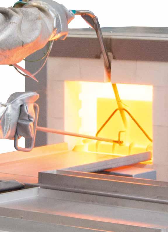
42 42


43 Chamber Furnaces Electrically Heated Chamber furnace N 41/H These universal chamber furnaces with radiation heating have been specifically designed to withstand heavy-duty use in the tool shop. They are particularly useful for processes such as tool making or for hardening jobs, e.g. annealing, hardening and forging. With help of various accessories, these furnaces can be customized to your application requirements. Chamber furnace N 321 with charging stacker Compact, robust design Deep furnace chamber with three-sides heating: from both side walls and bottom Heating elements on support tubes ensure free heat radiation and a long service life Bottom heating protected by heat conducting SiC tiles Stainless steel upper door jamb protects furnace structure when furnace is opened hot Base frame included in the delivery, N 7/H - N 17/HR designed as table-top model Exhaust opening in the side of the furnace, or on rear wall of chamber furnace in the N 31/H models and higher Temperature uniformity up to +/- 10 C according to DIN Low energy consumption due to multi-layer insulation Gas spring dampers provide for easy door opening and closing Heat resistant zinc paint for protection of door and door frame (for model N 81 and larger) Defined application within the constraints of the operating instructions NTLog Basic for Nabertherm controller: recording of process data with USB-flash drive Controls description see page 88 For additional features see separate catalog Thermal Process Technology I connection* in kg Model Tmax Inner dimensions in mm Volume Outer dimensions in mm Heating Electrical Weight C w d h in l W D H power in kw 3 N 7/H phase 60 N 11/H phase 70 N 11/HR phase 2 70 N 17/HR phase 2 90 Annealing furnace N 7/H, as table-top model N 31/H phase 210 N 41/H phase 260 N 61/H phase 400 N 87/H phase 480 N phase 820 N phase 910 N phase 1300 N phase 2100 N 81/ phase 900 N 161/ phase 1000 N 321/ phase 1500 N 641/ phase Table-top model *Please see page 89 for more information about supply voltage 2 Heating only between two phases 3 Depending on furnace design connected load might be higher 43
/(DIN material no. 1.4841) Larger plates and custom dimensions available upon request Charging plate Article no.")

44 Charging Plates for Models N 7/H - N 641/13 We recommend these accessories for applications up to 1100 C to protect the furnace floor, especially if a charging cart is used. Tmax 1100 C Three raised edges Heat-resistant alloy 314 (AISI)/(DIN material no ) Larger plates and custom dimensions available upon request Charging plate Article no. Furnace Outer dimensions in mm W D H N 7/H N 11/H, N 11/HR N 17/HR N 31/H N 41/H N 61/H N 87/H N 81, N 81/ N 161, N 161/ N 321, N 321/ N 641, N 641/ Annealing Boxes for Models N 7/H - N 161/13 Working with Annealing Boxes Annealing boxes are made of heat-resistant alloy 314 (AISI)/(DIN material no ) and also feature a lid for top charging. A ceramic fiber gasket is inserted in the circular seal profile on the upper edge of the box to seal it. To prevent oxidation during the process, neutral annealing coal is placed in the box. These bind the oxygen in the box. The oxygen inside the box is bound by the coal. After the heat treatment, the box is removed from the oven, the lid is opened using tongs and the workpiece removed. Our annealing boxes are also well suited for brazing. Annealing box with lid and granulate The boxes can also be used with the appropriate granulate for carburizing (also referred to as case hardening or cementing) and for powder nitriding or powder boriding. The workpieces are placed in the box with carburizing granulate or nitriding powder or boriding powder and a suitable activator. Tmax 1100 C Annealing box with lid and seal profile Lid sealing with ceramic fiber Also usable for carburizing and powder nitriding Heat-resistant alloy 314 (AISI)/(DIN material no ) 44 Annealing box on stacker Article no. Furnace Inner dimensions in mm Outer dimensions in mm Charging method w d h W D H of the box N 7/H charging fork N 11/H, N 11/HR charging fork N 17/HR charging fork N 31/H draw hook N 41/H draw hook N 61/H, N 87/H draw hook N 81, N 81/ charging cart N 161, N 161/ charging stacker Article no , 1 set of fiber insulation cord, 5 strips of 610 mm each Work space = box inner dimensions: - 30 mm to all sides Larger boxes and custom dimensions available upon request

45 Protective Gas Boxes for Models N 7/H - N 641/13 The annealing boxes for heat treatment under protective gas are equipped with a protective gas intlet and outlet. A box with protective gas is advisable for larger workpieces requiring defined heat treating. We would be pleased to carry out Trials at our technical center can be carried out on request. Up to furnace model N 61/H with downward door opening the gas ductway is laid through the upper section of the door collar, for larger furnaces with upward door opening the supply line is laid through the lower furnace collar. The box is pressurized with non flammable protective and reactive gases such as argon, nitrogen or forming gas via the protective gas tube. There are manual and automatic systems available for protective gas. See pages for more information about protective gases which can be used as well as manual and automatic protective gas systems. After charging the box it is closed and preflushed outside the furnace. Afterwards the box is placed in the preheated furnace. The quantity of gas can be reduced to the process flush quantity. After the heat treatment the box is pulled out of the furnace, the charge taken from the box and placed in the quenching medium. We recommend using binding wire on the parts so that they can easily be grasped by tongs. Box with protective gas connection A flexible type K thermocouple is installed in the box for measuring the temperature; we recommend connecting it to a digital display device or to a temperature recorder. The box can also be cooled down on a cooling platform while closed. Be sure that the protective gas flowrate is increased for this application. Tmax 1100 C For non-combustible protective and reactive gases argon, nitrogen and forming gas (observe national regulations) Protective gas box with fiber sealing and lid, gas supply via a tube into the bottom of the box Protective gas connection via quick coupling with hose connector (inner diameter 9 mm) Piping for gas inlet and outlet through the furnace collar Heat-resistant alloy 314 (AISI)/(DIN material no ) Charge thermocouple type K for temperature display or charge control N 7/H Additional equipment Starting from N 31/H a charging cart is recommended see page 78 Digital temperature display see page 69 Gas supply systems see page 74 Charging forks see page 47 Draw Hook see page 77 Winch stacker with protective gas box and furnace Article no. Furnace Inner dimensions in mm Outer dimensions in mm 1 Preflush rate Process flush rate Charging method w d h W D H l/min l/min of the box N 7/H charging fork N 11/H, N 11/HR charging fork N 17/HR charging fork N 31/H draw hook N 41/H draw hook N 61/H, N 87/H draw hook N 81, N 81/ charging stacker N 161, N 161/ charging stacker N 321, N 321/ charging stacker N 641, N 641/ charging stacker Article no , 1 set of fiber insulation cord, 5 strips of 610 mm each 1 Without piping Work space = box inner dimensions: - 30 mm to all sides Larger boxes and custom dimensions available upon request 45

46 Protective Gas Boxes with Evacuation Lid for Models N 7/H - N 614/13 For heat treatment of bulk goods and hollow parts under protective gas atmosphere we recommend the usage of protective gas boxes with an additional evacuation lid. These boxes are equipped with a lid for top charging, protective gas inlet and outlet as well as a evacuation lid with rubber sealing gasket. Gas ductwork and handling while hot is the same as the protective gas boxes described on page 45. In addition, these boxes also feature a connection for a vacuum pump with a shut-off valve. After charging the box in a cold state it is evacuated and afterwards flushed with protective gas. By repeating this process once or several times the results are considerably improved. After the box was flushed with protective gas the last time, the evacuation lid is removed and the box is placed into the preheated furnace. Protective gas is used for heat treatment. Thus traces of oxygen in the box can be reduced by a considerable amount which improves the quality of the components accordingly. After the heat treatment the box is taken out of the furnace and can be cooled in air or be opened to remove the charge. Protective gas box for N 41/H furnace with additional evacuation lid The box can also be force-cooled on a cooling platform while closed. Be sure that the protective gas flowrate is increased for this application. Tmax 1100 C For non-combustible protective and reactive gases argon, nitrogen and forming gas (observe national regulations) Protective gas box with fiber sealing and lid with locks, recess for evacuation lid, gas inlet via a pipe into the bottom of the box Evacuation lid with rubber sealing (Elastomer) and manometer Protective gas connection via threeway ball valve and quick coupling with hose connector (inner diameter 9 mm) Piping for gas inlet and outlet through the furnace collar Heat-resistant alloy 314 (AISI)/(DIN material no ) Charge thermocouple type K for temperature display or charge control Additional equipment Starting from N 31/H a charging cart is recommended see page 78 Digital temperature display see page 69 Vacuum pump see page 75 Gas supply systems see page 74 Charging forks see page 47 Draw Hook siehe Seite Article no. Furnace Inner dimensions in mm Outer dimensions in mm 1 Preflush rate Process flush rate Charging method w d h W D H l/min l/min of the box N 7/H charging fork N 11/H, N 11/HR charging fork N 17/HR charging fork N 31/H draw hook N 41/H draw hook N 61/H, N 87/H draw hook N 81, N 81/ charging stacker N 161, N 161/ charging stacker N 321, N 321/ charging stacker N 641, N 641/ charging stacker Article no , 1 set of fiber insulation cord, 5 strips of 610 mm each 1 Without piping and evacuation lid Work space = box inner dimensions: - 30 mm to all sides Larger boxes and custom dimensions available upon request
 631001017 N 17/HR Protective Gas Boxes with Hinged Lids for Fast Quenching for Models N 7/H - N 31/H For heat treatment of small amounts of bulk material or small")


47 Charging Forks Charging forks to charge and remove protective gas boxes up to model N 17/H Article no. Furnace N 7/H, N 11/H(R) N 17/HR Protective Gas Boxes with Hinged Lids for Fast Quenching for Models N 7/H - N 31/H For heat treatment of small amounts of bulk material or small parts under protective gases with subsequent fast quenching in oil or water, we recommend to use protective gas boxes with a hinged lid. Boxes with an angled hinged lid on the front are equipped with a protective gas line on the rear wall. The supply line is run through the upper furnace collar. After preflushing the box with non-flammable protective and reactive gases such as argon, nitrogen or forming gas 95/5, the box is placed with hinged lid first into the furnace. Due to a slight overpressure within the box the protective gas is vented off through the hinged lid. After the heat treatment the box is taken out of the furnace and the charge is poured into quenching bath directly out of the box. By placing the box at an angle the hinged lid opens by itself. The contact with ambient air is reduced to a minimum. Tmax 1100 C For non-combustible protective and reactive gases argon, nitrogen and forming gas (observe national regulations) Protective gas box with flap lid and gas supply from the rear wall Protective gas connection via quick coupling with hose connector (inner diameter 9 mm) Piping for gas inlet and outlet through the furnace collar Lid remains closed through its own weight Holder with hand handle Heat-resistant alloy 314 (AISI)/(DIN material no ) Charge thermocouple type K for temperature display or charge control Protective gas box with hinged lid Additional equipment Starting from N 31/H a charging cart is recommended see page 78 Digital temperature display see page 69 Gas supply systems see page 74 Article no. Furnace Inner dimensions in mm Outer dimensions in mm 1 Preflush rate Process flush rate w d h W D H l/min l/min N 7/H N 11/H, N 11/HR N 17/HR N 31/H Work space = box inner dimensions: - 30 mm to all sides 1 Without piping Larger boxes and custom dimensions available upon request 47


48 Gas Feed Boxes with Hinged Lid for Models N 7/H - N 87/H which Remain in the Furnace Gas connection Door Protective gas box with hinged lid for permanent operation Working with Protective Gas Boxes with Hinged Lid in continuous Operation In the case of successive protective gas heat treatment of individual parts, a gassing box is recommended, which remains in the furnace. For charging, the box is equipped with a flap lid to the front. The lid closes without a sealing profile against the oblique position of the box opening. Larger gas losses in comparison with removable boxes can be expected. For the protective gas supply the pipe goes through a bore on the rear wall of the furnace. For charging, the box is opened in the furnace using a draw hook and the workpieces are placed into the box. The box is continuously flushed with non-flammable protective and reactive gases such as argon, nitrogen or forming gas 95/5. Due to a slight overpressure within the box the protective gas is vented off through the hinged lid. After the heat treatment the box is opened using a draw hook and the workpieces are removed. Tmax 1100 C For non-combustible protective and reactive gases argon, nitrogen and forming gas (observe national regulations) Protective gas box with flap lid and gas supply from the rear wall Protective gas connection via quick coupling with hose connector (inner diameter 9 mm) Piping for gas inlet and outlet through the rear wall Front flap lid which opens downwards Heat-resistant alloy 314 (AISI)/(DIN material no ) Charge thermocouple type K for temperature display or charge control The furnace will not be equipped with a charging plate (protective gas box is permanently installed) Additional equipment Digital temperature display see page 69 Gas supply systems see page 74 Probes heat treated in different processes Article no. Furnace Inner dimensions in mm Outer dimensions in mm 1 Preflush rate Process flush rate w d h W D H l/min l/min N 7/H N 11/H, N 11/HR N 17/HR N 31/H N 41/H N 61/H N 87/H Work space = box inner dimensions: - 30 mm to all sides 1 Without piping Larger boxes and custom dimensions available upon request 48


49 Protective Gas Annealing Bag and Holder for Models N 7/H - N 87/H When workpieces made of air-hardened steel must be heat treated under protective gas and quenched afterwards, the protective gas annealing bag with holder is an optimal solution. This system consists of a holder with charge carrier and protective gas tube as well as a bag made of stainless steel heat treating foil. The charge is placed on the charge carrier and covered with the protective gas annealing bag. The bag is preflushed with non-flammable protective and reactive gases such as argon, nitrogen or forming gas 95/5 and placed together with the holder in the furnace. After the charge has been heated, the protective gas annealing bag and holder are removed from the furnace and cooled with the help of the forced cooling system or in still air. At the same time the workpiece remains in the bag in the protective gas atmosphere. This prevents oxidation from occuring. Due to thinwalled foil very rapid cooling times can be achieved. The protective gas annealing bag is also suitable for quenching workpieces in oil or water. The protective gas annealing bag with holder is taken out of the hot furnace after the heating time. The bag is pulled off the holder above the quenching bath using a heat protection glove. After this the workpiece can slide directly into the quenching bath. The short exposure to ambient air while being pulled out normally has only minimum effect on the surface oxidation of workpieces. The bags can be used multiple times. Our experience shows that at temperatures < 950 C the stainless steel heat treating bag lasts for approx processes. At temperatures between 950 C and 1050 C, use for approx processes can be assumed. Tmax 1100 C For non-combustible protective and reactive gases argon, nitrogen and forming gas (observe national regulations) Holder with protective gas annealing bag Supplied with three protective gas annealing bags Protective gas supply with quick lock and hose connector (inner diameter 9 mm) Protective protective gas through notch in upper furnace collar Holder with hand handle Heat-resistant alloy 314 (AISI)/(DIN material no ) Charge thermocouple type K for temperature display or charge control Protective gas annealing bag in operation Additional equipment Starting from N 31/H a charging cart is recommended see page 78 Digital temperature display see page 69 Gas supply systems see page 74 Thermocouple integrated in holder Article no. Furnace Useable inner dimensions in mm Replacement bag Bag dimensions in mm Preflush rate Process flush rate w d h (article no.) w d h l/min l/min N 7/H N 11/H, N 11/HR N 17/HR N 31/H N 41/H N 61/H, N 87/H


50 Stainless Steel Heat Treating Foil to avoid Surface Reactions Single parts requiring protection against decarburizing can be wrapped in a stainless steel heat treating foil off the roll or packed in prepared envelopes or bags. The rolls are available in various lengths and widths, the envelopes and bags are supplied in various dimensions. Foil off the roll can be cut to size using gold plates scissors and the workpiece can be wrapped to requirements. See page for more details about accessory supplies required, such as tongs and special gloves. The protected workpiece can now be loaded into the heated furnace. Due to the foil's thinness, it takes on the furnace temperature immediately and binds oxygen trapped in the foil packaging. There is then no oxygen present to oxidize the workpiece itself. The workpiece stays clean. After the appropriate dwell time in the furnace, the wrapped workpiece is immersed in the quenching medium. After quenching the foil is removed and the part is then tempered. Care should be taken to ensure that the foil is not too close to the workpiece as otherwise the foil may become damaged. If the workpiece should have several openings or gaps, and a large amount of oxygen can be wrapped up, these gaps can be filled in with foil pieces. This increases the foil surface area. The foil has very sharp edges. Use gloves and tools. Workpieces in foil heat treating Annealing and Heat Treating Foils Tmax 1200 C Stainless steel heat treating foil for single use Ultra-thin stainless steel heat treating foil for bright annealing of workpieces in all shaps and sizes Foil is cut to the correct size Workpieces are packed into the foil as closely as possible Airtight lock by means of folds of a fold lock or suitable tools (see below) Rapid heating of the foil binds the oxygen in the packed piece, preventing virtually all oxidation and decarburizing Quenching takes place with a foil, so the workpiece remains protected Rapid quenching Stainless steel heat treating foil Article no. Dimensions Width in mm Length in m Accessory Equipment for Processing Bags, Envelopes and Foils Art.-Nr , roll tongs We recommend using special protective gloves and tools for closing bags, envelopes and foils because the foil has very sharp edges and can be damaged if handled using conventional tools. Art.-Nr , fold lock Article no. Description Fold lock with rotating handle Roll tongs for annealing envelopes and bag Hynit L finger protection gloves for foil use 50


51 Annealing Envelopes Annealing envelopes useful up to Tmax 1200 C For hardening small parts Airtight lock by means of folds of a fold lock or suitable tools see page 50 Rapid heating of the foil binds the oxygen in the annealing envelope preventing virtually all oxidation and decarburizing Rapid quenching in air, oil or water, ensuring high dimensional accuracy Workpieces are placed as tightly as possible in the annealing envelope Envelopes made of ultra-thin stainless steel heat treating foil, welded on three sides, for single use Annealing envelopes Article no. Dimensions in mm Article no. Dimensions in mm Width Length Width Length Other dimensions available upon request Annealing Bags Annealing bag suitable for powder nitriding, boriding and high speed steel hardening up to approx C C for cold work purposes Made of stainless steel heat treating foil for single use For hardening of blocks, stamps, cutting plates, etc. Rapid heating binds the oxygen in the annealing bag so that high-alloy and medium-alloy steel grades can be hardened Rapid quenching in air, oil or water, ensuring high dimensional accuracy Workpieces are placed as tightly as possible into the annealing bag Airtight lock by means of folds of a fold lock or suitable tools see page 50 Annealing bags Quadratic cross-section Rectangular cross-section Article no. Dimensions in mm Article no. Dimensions in mm W D H W D H Other dimensions available upon request 51

52 Carburizing Granulate Carburizing granulate Workpieces are placed into an annealing box with carburizing granulate and the lid is closed and sealed At approx. 900 C the steel reacts with the carbon and forms an approx mm thick layer The thickness of the layer depends on the length of the process, approx. 0.1 mm/hr, a process time of approx. 6-8 hrs achieves good average results Powder for alloyed and non-alloyed steels as well as granulate for multiple use with approx. 20 % new granulate added Supplied in 25 kg sacks Article no. Description KG 6 - granulate for alloyed steels and multiple re-use KG 30 - granulate for non-alloyed steels and multiple re-use Nitriding Powder and Activator Nitriding powder Workpieces are placed into an annealing box together with the nitriding powder and activator and the lid is closed and sealed Powder nitriding causes a thin cover layer to form against friction wear and fatigue resistance is substantially increased At approx. 550 C an extremely thick cover layer forms (up to 1000 HV) which covers the hardened steel or the carburized edge layer. The activator improves process conditions. The process duration at 550 C is at least 10 hrs For all steels and cast iron, such as hot work steel matrices, injection molding dies, wear parts and machine components Anti-nitriding paste to protect areas which should not be processed 52 Article no. Description Container Nitriding powder 100 kg Activator 35 kg Activator 5 kg Anti-nitriding paste 2 kg


53 Process Examples Permanently installed protective gas box which ist loaded from the front Heat treatment under protective gas atmosphere in a protective gas box incl. charge thermocouple Protective gas box used in a large bogie hearth furnace with air circulation Protective gas box with flap which opens together with the furnace door Hardening in annealing tray with alloy bag Bulk material bright annealing in an annealing box with evacuation facility 53

. With a wide variety of optional equipment, these chamber furnaces can be optimally adapted to your processes.")


54 Chamber Furnaces with Brick Insulation or Fiber Insulation LH 60/12 with manual lift door and protective gas box for non-flammable protective or reactive gases Chamber furnace LH 30/14 The chamber furnaces LH 15/12 - LF 120/14 have been trusted for many years as professional chamber furnaces. These furnaces are available with either a robust insulation of light refractory bricks (LH models) or with a combination insulation of refractory bricks in the corners and low heat storage, quickly cooling fiber material (LF models). With a wide variety of optional equipment, these chamber furnaces can be optimally adapted to your processes. Cooling fan in combination with motor-driven exhaust air flap to reduce cooling time Tmax 1200 C, 1300 C, or 1400 C Dual shell housing with rear ventilation, provides for low shell temperatures High furnace chamber with five-sided heating for very good temperature uniformity Heating elements on support tubes ensure free heat radiation and a long service life Controller mounted on furnace door and removable for comfortable operation Protection of bottom heating and flat stacking surface provided by embedded SiC plate in the floor LH models: multi-layered, fiber-free insulation of light refractory bricks and special backup insulation LF models: high-quality non-classified fiber insulation with corner bricks for shorter heating and cooling times Door with brick-on-brick seal, hand fitted Short heating times due to high installed power Self-supporting arch for high stability and greatest possible protection against dust Quick lock on door Motor driven exhaust air flap Freely adjustable air slide intake in furnace floor Base included Defined application within the constraints of the operating instructions NTLog Basic for Nabertherm controller: recording of process data with USB-flash drive Controls description see page 88 Gas supply system for non-flammable protective or reaction gases Additional equipment Parallel swinging door, pivots away from operator, for opening when hot Lift door with electro-mechanic linear drive Separate wall-mounting or floor standing cabinet for switchgear 54
 for")


55 Chamber furnace LH 216/12SW with scale to measure weight reduction during annealing Cooling fan for shorter cycle times Protective gas connection to purge with non-flammable protective or reaction gases Manual or automatic gas supply system Scale to measure weight reduction during annealing Process control and documentation via VCD software package or Nabertherm Control Center (NCC) for monitoring, documentation and control see page 88 Chamber furnace LH 30/12 with manual lift door Model Tmax Inner dimensions in mm Volume Outer dimensions in mm Heating Electrical Weight C w d h in l W D H power in kw 2 connection* in kg LH 15/ phase LH 30/ phase LH 60/ phase 300 LH 120/ phase 410 LH 216/ phase 450 LH 15/ phase LH 30/ phase LH 60/ phase 300 LH 120/ phase 410 LH 216/ phase 460 LH 15/ phase LH 30/ phase LH 60/ phase 300 LH 120/ phase 410 LH 216/ phase 470 LF 15/ phase LF 30/ phase LF 60/ phase 270 LF 120/ phase 370 LF 15/ phase LF 30/ phase LF 60/ phase 270 LF 120/ phase Heating only between two phases *Please see page 89 for more information about supply voltage 2 Depending on furnace design connected load might be higher Parallel swinging door for opening when hot 55

56 Protective Gas Boxes for Models LH 15/.. - LH 216/.. Due to the cubic interior of the LH chamber furnaces and the corresponding protective gas boxes, these furnaces are ideally suited for higher batches. Gassing boxes for the LH models have a standard charge thermocuple, which can be used, for example, for charge control. The protective gas inlet and outlet is routed through the furnace collar in the case of a furnace with a swivel door on the left and through the lower furnace collar in the lift-door configuration. These boxes have a lid for charging from above, protective gas inlet and outlet. Tmax 1100 C For non-combustible protective and reactive gases argon, nitrogen and forming gas (observe national regulations) Protective gas box with fiber seal and cover with locks, inert gas introduction via a pipe into the bottom of the box Protective gas connection via quick coupling with hose connector (inner diameter 9 mm) Piping for gas inlet and outlet through the furnace collar Heat-resistant alloy 314 (AISI)/(DIN material no ) Charge thermocouple type K for temperature display or charge control Protective gas box for furnaces with hinged door Additional equipment Starting from LH 30/.. a charging cart is recommended see page 78 Digital temperature display see page 69 Gas supply systems see page 74 Extended gas piping for the use of smaller boxes in larger furnace models Draw hook see page 77 Charging stacker see page 79 Article no. Furnace Inner dimensions in mm Outer dimensions in mm 1 Charging method w d h W D H of the box LH 15/ draw hook LH 30/ draw hook LH 60/ draw hook LH 120/ draw hook LH 216/ charging stacker Article no , 1 set of fiber insulation cord, 5 strips of 610 mm each 1 Without piping Work space = box inner dimensions: - 30 mm to all sides Larger boxes and custom dimensions available upon request Protective Gas Boxes with Charging from the Front Design as the described protective gas boxes, but with charging from the front. These protective gas boxes remain in the oven and are equipped with a lid that can be opened to the front. After the lid has been opened, the batch can be removed directly. Protective gas box which stays in the furnace 56 Article no. Furnace Inner dimensions in mm Outer dimensions in mm 1 Charging method w d h W D H of the box LH 15/ LH 30/ LH 60/ LH 120/ Article no , 1 set of fiber insulation cord, 5 strips of 610 mm each 1 Without piping Work space = box inner dimensions: - 30 mm to all sides Larger boxes and custom dimensions available upon request


57 Protective Gas Boxes with Evacuation Lid for Models LH 15/.. - LH 216/.. Design as the described protective gas boxes, but with an additional evacuation lid. In order to reduce the residual oxygen in the box, protective gas boxes with evacuation lids can be used. These boxes have a lid for top loading, a protective gas inlet and outlet, and an evacuation cover with rubber gasket. The gas piping and the handling in the warm state corresponds to the gassing boxes on page 56. In addition, a connection for a vacuum pump via threeway ball valve is provided. In combination with a vacuum pump, the oxygen is evacuated from the box in cold state and afterwards flushed with protective gas. Repeating the process once or several times will significantly improve the results. After this process, the evacuation cover is removed and the actual heat treatment process is started under protective gas. After the heat treatment, the box is pulled out of the furnace and can be cooled in air or opened for batch removal. Protective gas box with fiber sealing and lid with locks, recess for evacuation lid, gas inlet via a pipe into the bottom of the box Evacuation lid with rubber sealing (Elastomer) and manometer Protective gas connection via threeway ball valve and quick coupling with hose connector (inner diameter 9 mm) Additional equipment Starting from LH 30/.. a charging cart is recommended see page 78 Digital temperature display see page 69 Vacuum pump see page 75 Gas supply systems see page 74 Extended gas piping for the use of smaller boxes in larger furnace models Draw hook see page 77 Charging stacker see page 79 Protective gas box with evacuation lid Article no. Furnace Inner dimensions in mm Outer dimensions in mm 1 Charging method w d h W D H of the box LH 15/ draw hook LH 30/ draw hook LH 60/ draw hook LH 120/ draw hook LH 216/ charging stacker Article no , 1 set of fiber insulation cord, 5 strips of 610 mm each 1 Without piping Work space = box inner dimensions: - 30 mm to all sides Larger boxes and custom dimensions available upon request Charging plates for Models LH 15/.. - LH 216/.. Charging plates are recommended to protect the furnace floor. The charging plates are particularly suitable for heat treatment with protective gas boxes in order to minimize wear during charging. Tmax 1100 C Threeside upstand Heat-resistant alloy 314 (AISI)/(DIN material no ) With spacer o the rear heating elements Article no. Furnace Outer dimensions in mm W D H LH 15/ LH 30/ LH 60/ LH 120/ LH 216/ Charging plate 57


58 Chamber Furnaces with Drawer Bottom or as a Bogie The NW chamber furnaces enable simple charging for cold-cold processes. The heat treatment can take place under air or under nonflammable protective gases with a protective gas box or protective gas hood. With a drawer mechanism (NW NW 300/H) the furnace table can be easily pulled out of the chamber furnace. The larger models NW NW 1000/H are designed as shuttle furnace with completely free traversing bogie. Free access in front of the furnace allows for a simplified and clear charging. Tmax 1300 C, 1100 C with protective gas box (additional equipment) Dual shell housing, galvanized steel sheets Double-walled door with front made of textured stainless steel Controller mounted on furnace door and removable for comfortable operation (up to model NW 440) Heating from five sides with special arrangement of heating elements for optimum temperature uniformity Heating elements of support tubes provide for free radiation of the heat Multi-layer insulation with light-weight refractory bricks and high-quality, energy-saving backing insulation Chamber furnace NW 440 with free traversing bogie Vaulted ceiling Furnace table can be pulled-out as drawer (NW NW 300) From chamber furnace NW 440 bogie on four castors (two with brakes) which can be pulled out completely. Accession assistance and removable drawbar for bogie SiC-floor plate protects floor elements and provides a level setting surface Door sealing grinded by hand (brick on brick); NW NW 300 Semi-automatic air inlet flap closes the air inlet at a temperature which can be set in the controller for NW NW 300 Exhaust air outlet in the ceiling, motor driven exhaust air flap for chamber furnaces NW NW 1000 Comfortable charging height with base of 800 mm (chamber furnaces NW NW 1000 = 500 mm) Defined application within the constraints of the operating instructions NTLog for Nabertherm controller: recording of process data with USB-flash drive Controls description see page 88 Additional equipment Protective gas boxes and hoods Manual or automatic gas supply system Process control and documentation via VCD software package or Nabertherm Control Center (NCC) for monitoring, documentation and control see page 88 Chamber furnace NW 300 with pulled-out furnace table Model Tmax Inner dimensions in mm Volume Outer dimensions in mm Connected Electrical Weight C w d h in l W D H load kw connection* in kg NW phase 400 NW phase 460 NW phase 560 NW phase 970 NW phase 1180 NW phase 1800 *Please see page 89 for more information about supply voltage 58

 Piping for gas inlet and outlet through the furnace collar")
 Charge thermocouple type K for temperature display or charge control Chamber furnace NW 200 with protective gas box Protective Gas Hoods Protective gas hoods consist of a and a bottom with a")
59 Protective Gas Boxes and Protective Gas Hoods for Chamber Furnaces NW NW 1000 Protective Gas Boxes These protective gas boxes have a cover with a sealing profile as well as a protective gas inlet and outlet. They are pulled out of the furnace in cold condition and charged from above. Tmax 1100 C For non-combustible protective and reactive gases argon, nitrogen and forming gas (observe national regulations) Protective gas box with fiber seal and cover with locks, inert gas introduction via a pipe into the bottom of the box Protective gas connection via quick coupling with hose connector (inner diameter 9 mm) Piping for gas inlet and outlet through the furnace collar Forklift receptive Heat-resistant alloy 314 (AISI)/(DIN material no ) Charge thermocouple type K for temperature display or charge control Chamber furnace NW 200 with protective gas box Protective Gas Hoods Protective gas hoods consist of a and a bottom with a sealing profile as well as protective gas inlet and outlet. After charging the bottom in front of the oven in cold condition, the hood is put on and the drawer or the car is pushed back into the oven. Design as protective gas boxes, but Gassing hood with eye for raising the hood by crane Hood bottom with sealing Piping for gas inlet and outlet at the hood through the furnace collar Protective gas box for similar furnace Additional equipment for protective gas boxes and hoods Digital temperature display see page 69 Gas supply systems see page 74 Two automatic gas sypply systems, connected with each other Furnace Article no. Inner dimensions in mm Article no. Inner dimensions in mm Charging Protective gas box w d h Protective gas hood w d h the furnace NW Drawer NW Drawer NW Drawer NW On a bogie NW On a bogie NW 1000 on request on request On a bogie Article no , 1 set of fiber insulation cord, 5 strips of 610 mm each Work space = box inner dimensions: - 30 mm to all sides Larger boxes and custom dimensions available upon request 59


")

60 Forced Convection Chamber Furnaces < 675 Liters Electrically Heated Forced convection chamber furnace NA 120/45 Forced convection chamber furnace NA 250/45 The very good temperature uniformity of these chamber furnace with air circulation provides for ideal process conditiones for annealing, curing, solution annealing, artificial ageing, preheating, or soft annealing and brazing. The forced convection chamber furnaces are equipped with a suitable annealing box for soft annealing of copper or tempering of titanium, and also for annealing of steel under non-flammable protective or reaction gases. The modular forced convection chamber furnace design allows for adaptation to specific process requirements with appropriate accessories. Forced convection chamber furnace NA 15/65 as table-top model Tmax 450 C, 650 C, or 850 C Stainless steel air-baffles in the furnace for optimum air circulation Swing door hinged on the right side Base frame included in the delivery, NA 15/65 designed as table-top model Horizontal air circulation Temperature uniformity up to +/- 4 C according to DIN (model NA 15/65 up to +/- 5 C) Optimum air distribution enabled by high flow speeds One frame sheet and rails for two additional trays included in the scope of delivery (NA 15/65 without frame sheet) Defined application within the constraints of the operating instructions NTLog Basic for Nabertherm controller: recording of process data with USB-flash drive Controls description see page 88 Forced convection chamber furnace NA 500/45S with four compartments, each with roller conveyor and individual door Additional equipment (not for model NA 15/65) Optimization of the temperature uniformity up to +/- 3 C according to DIN Air inlet and exhaust air flaps when used for drying Controlled cooling with fan Manual lift door (up to model N(A) 120/.. (HA)) Pneumatic lift door Air circulation with speed control, recommendable for processes with light or sensitive charge Additional frame sheet Roller conveyor in furnace chamber for heavy charges 60

 for monitoring, documentation and control see page 88 Roller conveyor in forced convection chamber furnace N 250/85HA Model Tmax Inner dimensions")
 450 290 420 260 30 1040 1290 1385 3.0 / 9.0 1(3)-phase 285 120 120 30 NA 60/45(LS) 450 350 500 350 60 1100 1370 1475 6.0 / 12.")
61 Forced convection chamber furnace NA 500/65 Forced convection chamber furnace N 250/85HA with quenching bath Annealing boxes Feed and charging aids Safety technology according to EN 1539 (NFPA 86) (models NA.. LS) for charges containing solvents Inlets, measuring frames and thermocouples for TUS measurements charge or comparative measurements Charge control Process control and documentation via VCD software package or Nabertherm Control Center (NCC) for monitoring, documentation and control see page 88 Roller conveyor in forced convection chamber furnace N 250/85HA Model Tmax Inner dimensions in mm Volume Outer dimensions in mm Heating Electrical Weight Heat-up time 5 Cool-down time 5 from Tmax power in kw 3 to Tmax to 150 C in minues C w d h in l W D H NA/NA.. LS connection* in kg in minutes Flaps 4 Fan cooling 4 NA 30/45(LS) / 9.0 1(3)-phase NA 60/45(LS) / phase NA 120/45(LS) / phase NA 250/45(LS) / phase NA 500/45(LS) / phase NA 675/45(LS) / phase NA 15/ phase NA 30/ phase N A 60/ phase NA 120/ phase NA 250/ phase NA 500/ phase NA 675/ phase N 30/85 HA phase N 60/85 HA phase N 120/85 HA phase N 250/85 HA phase N 500/85 HA phase N 675/85 HA phase Table-top model see page 60 *Please see page 89 for more information about supply voltage 2 Heating only between two phases 4 Additional equipment 3 Depending on furnace design connected load might be higher 5 Empty furnace 61

 Protective gas box with fiber seal and cover with locks, inert gas")
/(DIN material no. 1.")
62 Protective Gas Boxes for Models NA 30/45 - N 500/85HA Forced convection chamber furnace N 250/85 HA with protective gas box Protective gas box with insertations For the heat treatment, workpieces are placed in the box, the lid is locked using the sealing locks and flushed with protective gas outside the furnace for some time and then placed in the furnace. Depending on the weight, a charging cart (page 30) is recommended. Basic Version For non-combustible protective and reactive gases argon, nitrogen and forming gas (observe national regulations) Protective gas box with fiber seal and cover with locks, inert gas introduction via a pipe into the bottom of the box Protective gas connection via quick coupling with hose connector (inner diameter 9 mm) Piping for gas inlet and outlet through the furnace collar Models N 250/..HA, NA 250/.., N 500/..HA und NA 500/.. will be delivered without bootom frame sheet Heat-resistant alloy: 309 (AISI)/(DIN material no ) Charge thermocouple type K for temperature display or charge control Additional equipment Digital temperature display see page 69 Gas supply systems see page 74 Extended gas piping for the use of smaller boxes in larger furnace models Draw hook see page 77 Charging cart see page 78 Protective gas box with extended piping for usage in a large furnace model 62 Article no. Furnace Inner dimensions in mm Outer dimensions in mm 1 Charging method (Furnace with hinged door) (Furnace with lift door) w d h W D H of the box NA 30/.., N 30/..HA draw hook NA 60/.., N 60/..HA draw hook NA 120/.., N 120/..HA draw hook NA 250/.., N 250/..HA charging stacker NA 500/.., N 500/..HA charging stacker Article no , 1 set of fiber insulation cord, 5 strips of 610 mm each 1 Without piping Work space = box inner dimensions: - 30 mm to all sides Larger boxes and custom dimensions available upon request

63 Protective Gas Boxes with Evacuation Lid for Models NA 30/45 - N 500/85HA Design as the boxes described above, but with additional evacuation lid and connection. Before the box is placed in the furnace, in a cold state an evacuation and protective gas atmosphere are alternately generated to force out the oxygen and achieve a pure atmosphere. Protective gas box with fiber sealing and lid with locks, recess for evacuation lid, gas inlet via a pipe into the bottom of the box Evacuation lid with rubber sealing (Elastomer) and manometer Protective gas connection via threeway ball valve and quick coupling with hose connector (inner diameter 9 mm) Piping for gas inlet and outlet through the furnace collar Protective gas box with evacuation lid Additional equipment Digital temperature display see page 69 Vacuum pump see page 75 Gas supply systems see page 74 Extended gas piping for the use of smaller boxes in larger furnace models Draw hook see page 77 Charging cart see page 78 Article no. Furnace Inner dimensions in mm Outer dimensions in mm 1 Charging method (Furnace with hinged door) (Furnace with lift door) w d h W D H of the box NA 30/.., N 30/..HA draw hook NA 60/.., N 60/..HA draw hook NA 120/.., N 120/..HA draw hook NA 250/.., N 250/..HA charging stacker NA 500/.., N 500/..HA charging stacker Article no , 1 set of fiber insulation cord, 5 strips of 610 mm each 1 Without piping and evacuation lid Work space = box inner dimensions: - 30 mm to all sides Larger boxes and custom dimensions available upon request 63
 SAT thermocouple Controller Protective Gas Boxes According to AMS 2750 E, Instrumentation Type D for Forced Convection Furnaces These boxes are")

64 Protective Gas Boxes for Automotive (CQI-9) and Aeronautic (AMS7NADCAP) Norms Lid for TUS measurements Protective gas box Over-temperature protection TUS recorder Controlling thermocouple (Furnace) Charging thermocouple/controlling thermocouple (box) SAT thermocouple Controller Protective Gas Boxes According to AMS 2750 E, Instrumentation Type D for Forced Convection Furnaces These boxes are based on the standard protective gas boxes for furnaces with hinged door. To fulfill AMS 2750 E, instrumentation, type D requirements the boxes are equipped with necessary measuring ports. Temperature uniformity class 2: +/- 5 C in useful space Additional port for customers flexible SAT thermocouple with max. 1,5 mm diameter Thermcouple, overtemperature protection, metal clad thermocouple, type N with plug Article no. Furnace Inner dimensions in mm Outer dimensions in mm 1 (Furnace with swinging door) (Furnace with lift door) w d h W D H NA 30/.., N 30/..HA NA 60/.., N 60/..HA NA 120/.., N 120/..HA NA 250/.., N 250/..HA NA 500/.., N 500/..HA Article no , 1 set of fiber insulation cord, 5 strips of 610 mm each 1 Without piping Work space = box inner dimensions: - 30 mm to all sides Larger boxes and custom dimensions available upon request Protective Gas Boxes with Evacuation Lid According to AMS 2750 E, Instrumentation type D These boxes are based on the standard protective gas boxes with evacuation lid for furnaces with hinged door. Before the box is placed in the furnace, in a cold state an evacuation and protective gas atmosphere are alternately generated to force out the oxygen and achieve a pure atmosphere. Temperature uniformity class 2: +/- 5 C in useful space Additional port for customers flexible SAT thermocouple with max. 1,5 mm diameter Thermcouple, overtemperature protection, metal clad thermocouple, type N with plug Protective gas box with evacuation lid according to AMS 2750 E Article no. Furnace Inner dimensions in mm Outer dimensions in mm 1 (Furnace with hinged door) (Furnace with lift door) w d h W D H NA 30/.., N 30/..HA NA 60/.., N 60/..HA NA 120/.., N 120/..HA NA 250/.., N 250/..HA NA 500/.., N 500/..HA Article no , 1 set of fiber insulation cord, 5 strips of 610 mm each 1 Without piping Work space = box inner dimensions: - 30 mm to all sides Larger boxes and custom dimensions available upon request 64

 with the following changes Tmax 450 C and 650 C Silicone door seal Furnace housing sealed with silicone Protective gas connection")
65 Sealed Forced Convection Chamber Furnaces NA-I and NA-SI Sealed forced convection chamber furnaces are suitable if a heat treatment process up to 650 C requires a protective gas atmosphere that does not have to be completely oxygen free. The difference between the two variants is that the I-model only has a sealed outer housing while the SI-model has a welded inner box, which further reduces the residual oxygen concentration. NA-I design Like forced convection chamber furnaces < 675 l (page 60) with the following changes Tmax 450 C and 650 C Silicone door seal Furnace housing sealed with silicone Protective gas connection in the back wall Defined application within the constraints of the operating instructions Residual oxygen concentration < 1 % depending on the volume and type of protective gas For non-flammable protective and reaction gases such as argon, nitrogen, and forming gas (national regulations must be considered) Forced convection chamber furnace NA 120/65 I NA-SI design Additional features Tmax 650 C Welded inner housing 2-sided heating and air circulation Door sealed with seal gas Sealed connection to circulation motor Gas inlet via circulator shaft Defined application within the constraints of the operating instructions Residual oxygen concentration to 0.1 % depending on the volume and type of protective gas For non-flammable protective and reaction gases such as argon, nitrogen, and forming gas (national regulations must be considered) Forced convection chamber furnace NA 15/65 I as tabletop model with manual gas supply system Model Tmax Inner dimensions in mm Volume Outer dimensions in mm Heating Electrical Weight C w d h in l W D H power in kw 3 connection* in kg NA 30/45 I (3)-phase 285 NA 60/45 I phase 350 NA 120/45 I phase 460 NA 250/45 I phase 590 NA 500/45 I phase 750 NA 675/45 I phase 900 NA 15/65 I phase 60 NA 30/65 I phase N A 60/65 I (SI) phase 350 NA 120/65 I (SI) phase 460 NA 250/65 I (SI) phase 590 NA 500/65 I (SI) phase 750 NA 675/65 I phase Table-top model *Please see page 89 for more information about supply voltage 2 Heating only between two phases 3 Depending on furnace design connected load might be higher 65


66 Forced Convection Pit-Type Furnaces Electrically Heated Basket system for charging in different layers Pit-type furnace SAL 120/65 with protective gas retort box and cooling station next to the furnace Forced convection pit-type furnaces offer the advantage of easy charging, for heat treatment of heavy parts or loads in charge baskets. With maximum application temperatures available from 450 C to 850 C, these compact pit-type furnaces are particularly useful for processes such as tempering, solution annealing, artificial ageing, and soft annealing. Tmax 450 C, 650 C, 850 C Air circulation fans in the furnace bottom, high circulation rate Vertical air circulation with square air heating chamber Temperature uniformity up to +/- 4 C according to DIN Interior walls from stainless steel Switchgear with solid-state relays Defined application within the constraints of the operating instructions NTLog Basic for Nabertherm controller: recording of process data with USB-flash drive Controls description see page 88 SAL 250/65 Additional equipment Charging hoist with swivel arm and charge basket Optimization of the temperature uniformity up to +/- 2 C according to DIN Integrated fan for rapid cool down or separate cooling station for annealing box cooling outside of the furnace Annealing box with protective gas inlet and outlet for production in a defined atmosphere Manual or automatic gas supply systems for non-flammable protective or reaction gases Process control and documentation via VCD software package for monitoring, documentation and control see page 88 Model Tmax Inner dimensions in mm Volume Max. charging weight Outer dimensions in mm Heating Electrical Weight C w d h in l in kg W D H power in kw 2 connection* in kg SAL 30/ phase 130 SAL 60/ phase 225 SAL 120/ phase 280 SAL 250/ phase 750 SAL 500/ phase 980 SAL 30/ phase SAL 60/ phase 225 SAL 120/ phase 280 SAL 250/ phase 750 SAL 500/ phase 980 Protective gas box, AMS 2750 E design SAL 30/ phase SAL 60/ phase 225 SAL 120/ phase 280 SAL 250/ phase 750 SAL 500/ phase Heating only between two phases *Please see page 89 for more information about supply voltage 2 Depending on furnace design connected load might be higher 66


67 Charging Aid for Models SAL 30/45 - SAL 500/85 A charging aid, fastened to the furnace consisting of a swivel arm and winch is recommended for charging series SAL 30/45A - SAL 250/85 forced convection pit-type furnaces with protective gas boxes or baskets. This allows easy and safe furnace charging. Swivel arm, mounted on side of furnace For ease of charging and removal of Nabertherm charging baskets and protective gas boxes Winch with hand crank Max. charging weight 140 kg Furnace Total height in mm SAL 30/.. - SAL 120/ SAL 250/ SAL 500/ Swivel arm mounted on furnace Protective Gas Boxes for Models SAL 30/45 - SAL 500/85 For tempering and bright annealing, workpieces are laid in the box, the lid is pressed firmly shut using the sealing locks and flushed with protective gas outside the box for some time and then placed in the furnace. Due to weight reasons we recommend to use a charging aid for charging. For non-combustible protective and reactive gases argon, nitrogen and forming gas (observe national regulations) Protective gas box with fiber seal and cover with locks, inert gas introduction via a pipe into the bottom of the box Protective gas connection via quick coupling with hose connector (inner diameter 9 mm) Piping for gas inlet and outlet through the furnace collar Heat-resistant alloy: 450 C (AISI)/(DIN material no ), 650 C (AISI)/(DIN material no ) or 850 C (AISI)/(DIN material no ) Charging aid lifting eyes Charge thermocouple type K for temperature display or charge control Additional equipment Digital temperature display see page 69 Gas supply systems see page 74 Protective gas box with sealing lock Article no. with charge Furnace Inner dimensions in mm Outer dimensions in mm 1 thermocouple w d h W D H SAL 30/ SAL 60/ SAL 120/ SAL 250/ SAL 500/ SAL 30/ SAL 60/ SAL 120/ SAL 250/ SAL 500/ SAL 30/ SAL 60/ SAL 120/ SAL 250/ SAL 500/ Article no , 1 sales unit of fiber insulation cord, 5 strips of 610 mm each 1 Without piping 67
/(DIN material no. 1.4301), 650 C - 321 (AISI)/(DIN material no.")

68 Charging Baskets for Models SAL 30/45 - SAL 500/85 The workpieces are placed in basket for tempering. We recommend the use of a charging aid for charging. Heat-resistant charging basket for small parts and bulk materials, incl. handle or crane lifting eyes Filling from above Hole size 12 mm Heat-resistant alloy: 450 C (AISI)/(DIN material no ), 650 C (AISI)/(DIN material no ) or 850 C (AISI)/(DIN material no ) Charging basket for top charging Article no. Furnace Inner dimensions in mm w d h SAL 30/ SAL 60/ SAL 120/ SAL 250/ SAL 500/ SAL 30/ SAL 60/ SAL 120/ SAL 250/ SAL 500/ SAL 30/ SAL 60/ SAL 120/ SAL 250/ SAL 500/ The workpieces are placed on different levels for tempering. We recommend the use of a charging aid for charging. Heat-resistant charging basket, incl. handle/crane lifting eyes Charged from side via 2 drawers (3 levels) Hole size 12 mm Heat-resistant alloy: 450 C (AISI)/(DIN material no ), 650 C (AISI)/(DIN material no ) or 850 C (AISI)/(DIN material no ) Special charging basket with 3 drawers (4 levels) for side charging Article no. Furnace Inner dimensions in mm w d h SAL 30/ SAL 60/ SAL 120/ SAL 250/ SAL 500/ SAL 30/ SAL 60/ SAL 120/ SAL 250/ SAL 500/ SAL 30/ SAL 60/ SAL 120/ SAL 250/ SAL 500/ The workpieces are placed on different levels for tempering. We recommend the use of a charging aid for charging. Heat-resistant charging basket for small parts and bulk materials, incl. handle/crane lifting eyes Charged in different floors Hole size 12 mm Heat-resistant alloy: 450 C (AISI)/(DIN material no ), 650 C (AISI)/(DIN material no ) or 850 C (AISI)/(DIN material no ) 68 Basket for charging in different floors Article no. Furnace No. of Max. charge weight per basket Inner dimensions in mm baskets w d h SAL 250/ kg


69 Temperature Measurement in Gas Supply Systems The use of a thermometer with thermocouple is recommended for determining the exact heat treatment temperature in protective gas boxes or gas feed annealing bags with holders. The thermocouple is permanently mounted on the respective protective gas boxes or gas feed annealing bag holder. A simple manual thermometer with LCD display or a temperature indicator with LED display can be supplied, mounted in a separate metal housing. Both are equipped with a two-pole plug unit for connecting to the thermocouple. The temperature can be determined in this way and, if necessary, readjusted on the controller. Upon request, the furnace can be operated by charge control with a thermocouple attached to the workpiece. Article no. Description Temperature indicator with digital display, 230 V 1/N connection, in metal housing Temperature indicator with digital display, battery-operated, manual device V Connecting cable between heat treatment with charge thermocouple and Article no , 5 m V Connecting cable between heat treatment with charge thermocouple and Article no , 3 m Thermostat (manual device) TUS Measuring Frame for Protective Gas Box To carry out the temperature uniformity measurement (TUS) the protective gas box will be equipped with a second lid. The TUS measuring frame is fixed to the lid and it is equipped with measuring port for thermocouples. Tmax 1100 C Useful for all relevant TUS norms Under the assumption that the furnace is equipped with a measuring port for themocouples Heat-resistant alloy 314 (AISI)/(DIN material no ) Thermocouples not included TUS Measuring Frame for Protective Gas Box 69

70 Tool Shop Hardening System KHS 17 The work platform of the system is designed to carry an N 7/H - N 17/H series hardening furnace and NA 15/65 annealing furnace. Suitable protective gas boxes can be used. A movable oil/water bath for quenching and subsequent cleaning is positioned below the furnaces. This compact system is a practical solution is space is an issue. After heat treatment in the hardening furnace, the parts are removed from the furnace or the gas feed box and quenched in an oil quench bath or water bath. The charging basket can be used to move the part within the bath so that it cools more evenly. After quenching in oil the workpiece should be cleaned in the water bath, dried and immediately tempered in a forced convection furnace in order to optimally fix the mechanical components with regard to their strength behavior for the required conditions, minimize distortion and prevent potential flaws. Additional equipment Protective gas boxes see page Protective gas annealing bag and holder see page 49 Gas supply systems see page 74 Charging forks see page 47 Tool shop hardening system KHS 17 Model Tmax Inner dimensions in mm Volume Outer dimensions in mm Heating Electrical Weight C w d h in l W D H power in kw 2 connection* in kg N 7/H phase 60 N 11/H phase 70 N 11/HR phase¹ 70 N 17/HR phase¹ 90 N 15/65HA phase 55 ¹Heating only between two phases *Please see page 89 for more information about supply voltage 2 Depending on furnace design connected load might be higher Article no. Article Outer dimensions in mm Charging floor grid dimensions W D H Width in mm length in mm Work table with quenching and cleaning bath Charging basket for quenching and cleaning bath

71 Tool Shop Hardening System MHS 17 The MHS 17 hardening system has a modular design and consists of a work platform for the heat treating furnaces, an oil bath for quenching and water bath for cleaning parts. As an option both baths can be delivered incl. heating. The baths are mounted to the left and right of the work platform and have charging baskets in order to induce even cooling of the parts in the bath. All parts may be ordered separately meaning the hardening system can be retrofitted or equipment added individually depending on the materials processed. The MHS 17 can have an air quenching system added to it for air-hardened steels. This platform has a powerful cooling fan to force cool the parts requiring hardening and also the gas feed annealing bag and holder. A refractory brick base is for placing hot boxes and workpieces on them. The quenching baths can also be fastened onto the forced cooling system. MHS 17 An additional storage platform can be integrated within the system for holding accessory equipment and/or optional charging accessories. Additional equipment see page 70. Model Tmax Inner dimensions in mm Volume Outer dimensions in mm Heating Electrical Weight C w d h in l W D H power in kw 2 connection* in kg for MHS 17 N 7/H phase N 11/H phase 70 N 11/HR phase¹ 70 N 17/HR phase¹ 90 N 15/65HA phase 55 ¹Heating only between two phases *Please see page 89 for more information about supply voltage 2 Depending on furnace design connected load might be higher Article no. Article Outer dimensions in mm Volume Charging floor grid dimensions Connected Supply W D H in l Width in mm length in mm load kw voltage Work platform Oil bath Water bath Heating element (oil bath) ,0 230 V Heating element (water bath) ,0 230 V Forced cooling system (cooling platform) ,2 230 V Side platform

72 Tool Shop Hardening Systems MHS 31, MHS 41 and MHS 61 These toolshop hardening systems are suitable for hardening larger components in air or under a protective gas atmosphere. The systems can be assembled from a chamber furnace, a forced convection furnace, a protective gas box with a gas supply via a solenoid valve, a charging plate to protect the furnace floor, and a quenching bath with heating element. During the heat treatment under protective gas, the process starts with the flushing of the batch in the protective gas box by means of protective gas. Subsequently, annealing is carried out in the chamber furnace at a lower process flushing rate. The chamber furnace is opened after the annealing process and the batch is removed from the protective gas box to be quenched in the preheated quench bath. The final annealing process takes place in the forced convection furnace. For easier charging, we recommend the use of optional charging aids such as pull hooks and charging trolleys. The toolshop hardening systems are an assembly of furnaces and accessories from our standard range. All components can also be ordered separately. Additional equipment Draw hook see page 77 Charging cart see page 78 Model Tmax Inner dimensions in mm Charging height Outer dimensions in mm Heating Electrical Weight C w d h in mm W D H power in kw 2 connection* in kg MHS 31 N 31/H phase 210 NA 30/ phase¹ 285 Quenching bath Q Heating element phase - MHS 41 N 41/H phase 260 NA 60/ phase 350 Quenching bath Q Heating element phase - MHS 61 N 61/H phase 400 NA 60/ phase 350 Quenching bath Q Heating element phase - Acces- Charging cart CW sories Charging cart CWK ,2 1-phase - Side platform Protective gas box N 31/H Protective gas box N 41/H ¹Heating only between two phases *Please see page 89 for more information about supply voltage 2 Depending on furnace design connected load might be higher 72


73 Protective Gas Hardening System SHS 41 This compact, semi-automatic system is suitable for hardening in a protective gas atmosphere followed by quenching of the workpiece in oil. In this way, even larger parts can be annealed under a protective gas and quenched. It consists of a chamber furnace N 41/H hardening furnace with a pneumatic door opening and charging plates as well as an oil quench bath on rollers with an integrated pneumatic lowering unit, a floor grid with gas hood, a holding unit for the gas hood as well as a rim exhaust with flame trap. The workpiece is placed on the floor grid and covered with the gas hood. After preflushing with protective gas, the gas hood is pushed with the floor grid into the chamber furnace. After the heat treatment is completed, the workload is pulled out of the furnace onto the lowering unit. The hood remains above the quenching bath while the charging floor grid is lowered pneumatically. In order to obtain best quenching results, the pneumatic lowering unit is moved up and down in the oil quench bath. After completion, the workload is moved into unloading position. This low cost system can be used for hardening processes which otherwise could only be handled in complex furnace systems. Chamber furnace N 41/H Pneumatic pedal switch operated door opening Charging plate Oil quench bath on rollers Pneumatic lowering unit Heating of oil quench bath Oil temperature display Charging floor grid and gas hood Holding unit for gas hood Manual protective gas unit see page 74 Draw hook see page 77 Safety equipment consisting of rim exhaust with flame trap and oil steam separator Protective gas hardening system with furnace N 41/H Additional equipment Suction hood Water bath Furnace Tmax Inner dimensions in mm Volume Outer dimensions in mm Heating Electrical Weight Model C w d h in l W D H power in kw 2 connection* in kg N 41/H¹ phase 260 ¹Furnace description see page 43 *Please see page 89 for more information about supply voltage 2 Depending on furnace design connected load might be higher Article no. Protective gas hood size in mm Oil quench bath max. load max. quench Preflush Process Heating power Electrical hardening system W D H size in liters Weight yield/h rate flush rate oil bath/kw connection* - SHS kg 20 kg phase Gas hood (spare part) *Please see page 89 for more information about supply voltage 73

74 Gas Supply Systems Protective Gases Protective gases are used to force oxygen out of the gas feed boxes mentioned above. Make sure to use protective gases behaving neutrally toward the heat treated part. The protective gases should be inert, meaning no chemical bonding should occur with the workpiece or the furnace and no reactions should be enduced. In many cases, nitrogen is used as protective gas (lighter than air). Our experience shows that nitrogen does not always lead to sufficient results. A longer preflush time must also be used. Better results are achieved by adding a mixture of nitrogen and adding some hydrogen. Hydrogen acts as a reducing constituent and reacts with the oxygen. This gas mixture is known as forming gas and available in stores. Experience has shown that adding 5 % hydrogen to the nitrogen leads to good results. According to the EU material safety data sheet this mixture is considered as not flammable. National regulations, however, must be observed. This gas can be obtained in premixed form. No measures must be taken in advance to prevent explosions. If the workpiece has an affinity to hydrogen, argon used as protective gas can lead to good results. Argon is a gas which is heavier than air. This makes it relatively easy to fill the protective gas containers. Forming gas with added hydrogen (depending on the country law up to a ration of 98/2) is lighter, but it has the advantage of burning at higher temperatures and therefore binds with the oxygen. Even in a cold state, the leaking hydrogen transports the oxygen very easily out of the container. For gas mixtures with hydrogen or other combustible gases, the valid safety regulations must always be observed. If the mixture is declared as combustible, the furnace, provided it is a gas tight version, can be fitted with a corresponding safety system. Always make sure that the room is properly ventilated when working with protective gases. Country-specific safety regulations must also be followed. Manual Gas Feed Fitting for Bottles Pressure reducing valve with assembled flow meter and attached pressure gauge indicating the bottle pressure The assembled variable area flow meter ensures good readability of the amount used Connection: screw connection for bottle Exit: hose connection (inner diameter 9 mm) 200 bar intake pressure, 4 bar outlet pressure Incl. 4 m connecting hose to the furnace Pressure reducing valve with assembled flow meter 74 Article no. Type of gas Flow rate l/min Ar N Non-flammable forming gas 0-30 Alternative connection threads on request
 200 bar intake pressure, 4 bar outlet pressure Incl. 4 m connecting hose to the furnace Available only in combination with furnace or switchgear Article no.")


75 Gas Feed Fitting with Solenoid Valve Solenoid valve mounted on the furnace, controlled using the controller "Extra" function Connection: screw connection for bottle Exit: hose connection (inner diameter 9 mm) 200 bar intake pressure, 4 bar outlet pressure Incl. 4 m connecting hose to the furnace Available only in combination with furnace or switchgear Article no. Type of gas Flow rate l/min Ar N Non-flammable forming gas 0-30 Alternative connection threads on request Automatic Gas Supply System for two different Flushing Quantities, e.g. high Volume Preflushing and low Volume for ongoing Operation Consisting of: Switching system with 3-step switch for gas inlet Off/Manual/Automatic via "Extra" function of respective controller, timer for switching from large gas quantity to small gas quantity. Gas feed stops at when program quits Automatic gas feed panel with pressure reducer, two adjustable flow meters and two solenoid valves, preinstalled conduit and wiring attached to furnace from the side on an assembly plate. Connection: hose connection (inner diameter 9 mm) Exit: hose connection (inner diameter 9 mm) Max. 10 bar intake pressure, max. 300 mbar outlet pressure Incl. connecting hose between furnace and protective gas box or gas connection Available only in combination with furnace or switchgear Automatic gas supply system for two flushing quantities Article no. Type of gas Flow rate l/min Ar N Non-flammable forming gas 4-80 Vacuum Pump Oil sealed rotary vane vacuum pump for universal use within the low vacuum range. Highly compact and low noise construction. Manometer included in delivery. Sliding vane rotary pump with sucking capacity of max. 16 m³/h 0,5 mbar absolute Connection hose made of stainless steel 2000 mm Connector KF16 Manometer (-1/0.6 bar) Article no. Outer dimensions in mm Connections on suction side Connected Supply Nominal suction power Suction capacity W D H load voltage* m 3 h m 3 h-l /4" 1/2" inner thread 0.55 kw 230 V *Article no. for other possible supply voltages on request Vacuum pump 75


76 Gloves Article no.: Specially insulated gloves for working with hot mechanical components and working near furnace Article no. Description Short-time contact temperature in C Fiberglass finger glove, 380 mm long approx Mitten, 280 mm long approx Finger glove, 300 mm long approx Fiberglass mitten, 380 mm long approx Carbon-fiber finger glove, knitted approx. 650 Heat-Resistant Face Mask Light design with adjustable hat size Plastic window, folds up Article no. Description Heat-resistant face mask Frontal Protection Coat Frontal heat protection Open back Velcro fastener on the back Material Preox-Aramid-Aluminium For radiated heat up to 1000 C, max. 95 sec. C3-classification according to EN C Length 1300 mm 76 Article no. Description Frontal Protection Coat, Size 54 (D), 1300 mm


77 Draw Hook For charging protective gas annealing bags with holder, annealing and protective gas boxes Large handle, also easy to handle with glove Article no. Length in mm Binding Wire For binding workpieces to allow easy removal from boxes Annealed twice and safe from breakage during charging Article no. Wire Ø in mm Container kg ring kg ring kg ring kg ring kg ring Hardening Tongs Various shapes and sizes for different applications and workpiece geometries Handle length 600 mm, assuring sufficient distance from hot furnace chamber and for deep immersion length into quench bath Article no Article no. Description Tongs with flat jaw suitable for hand forming Tongs with vertical mouth for lifting off floor Tongs with bent mouth, universal use Tongs with double-curve jaw, universal use Half round tongs, for round rod materials Knee tongs for larger rings with thick wall Handy universal tongs for small parts (handle length 500 mm)


 1, CW(K) 15 and CW(K) 16 For charging larger workpieces and annealing boxes.")
78 Cooling Platforms for Models N 17/HR, N 61/H, N 161 Storage platforms are used for forced cooling of mechanical components or annealing boxes outside of the furnace. The platform can also be used for charging the box in front of the furnace. Fan with 25 m³/min ambient air Article no. Furnace Outer dimensions in mm Connected Supply Comments load W D H kw voltage* up to N 17/HR V The same as forced cooling system MHS 17 see page up to N 61/H V The same as CWK1 charging trolley see page up to N V *Article no. for other possible supply voltages on request Charging Devices with and without Cooling Fan for Models N 31/H - N 641/13, N 30/45 HA - N 500/85 HA, LH (LF) 15/.. - LH (LF) 216/.. Charging Cart CW(K) 1, CW(K) 15 and CW(K) 16 For charging larger workpieces and annealing boxes. 4 casters, freely movable Equipped with a rack at working height for temporary storage Fixing lock for annealing bags (CWK) CWK version with cooling fan (0.2 kw, 230 V) Charging cart CWK1 Article no. Designation Furnace Outer dimensions in mm W D H CW 1 N 31/H, N 41.., N 61.., N 30/..HA, N 60/..HA CW 15 LH(LF) 15/.. - LH(LF) 60/ CW 16 LH(LF) 120/.. - LH(LF) 216/ CWK 1 N 31/H, N 41.., N 61.., N 30/..HA, N 60/..HA CWK 15 LH(LF) 15/.. - LH(LF) 60/ CWK 16 LH(LF) 120/.. - LH(LF) 216/ Art.-No. for NA 30/.. and NA 60/.. on request 1 Side switch Charging Cart CW 2 - CW 4 and CWK 2 - CWK 4 For charging larger workpieces and annealing boxes. 2 casters, 2 fixed rollers for heavy loads Equipped with a grid at working height for temporary storage Furnace locking via pedal lever CWK version with cooling fan (0,9 kw, 230 V) Charging cart CW 2 Article no. Designation Furnace Outer dimensions in mm W D H CW 2 N 81.., N 161.., N 120/..HA CW 3 N CW 4 N CWK 2 N 81.., N 161.., N 120/..HA CWK 3 N CWK 4 N Art.-No. for NA 120/.. on request 1 Side switch *Please see page 89 for more information about supply voltage 2 Without holding grip 78


79 Charging Cart WS 81 and WS 12 For charging of protective gas and annealing boxes. 2 casters, 2 fixed rollers for heavy loads Parallel guided lift, approx. 20 mm Max. charging weight 80 kg Guiding track, mounted at the furnace base frame Guiding track and charging cart can be also ordered separately Article no. Designation Furnace WS 81 N WS 12 N 120/..HA Art.-No. for NA 120/.. on request Charging Stacker WS 81 Charging Stacker WS 25 - WS 321 Lifting device with hand winch Compact construction with push bar and manual lifting device for easy and safe lifting 2 casters, 2 fixed rollers Adjustable loading fork width Max. charging weight 500 kg Guiding track, mounted at the furnace base frame Guiding track and forklift can be also ordered separately WS 50 charging stacker Article no. Designation Furnace WS 161 N WS 321 N WS 25 N 250/..HA WS 50 N 500/..HA Art.-No. for NA 250/.. and NA 500/.. on request Guiding track at the base frame WS 641 Charging Stacker Design as charging stacker WS 25 - WS 321, but Lifting device with manual hydraulic Max. charging weight 700 kg Article no. Designation Furnace WS 641 N Charging stacker WS 641 with chamber furnace N 641 and guiding track at the base frame 79


 load kw voltage* 631001014 Q 50 3 230 V 631001012 Q 200 6 400 V *Article no.")
80 Quenching and Cleaning Baths Baths for quenching in oil or water as well as for cleaning and degreasing are available as single or double baths and are made of stainless steel. Oil quench bath assure highly even cooling of workpieces and are equipped with a lid to immediatley extinguish ignited oil. For optimal results, pre-tempering water baths for cleaning workpieces should have an appropriate degreasing additive mixed in to the water bath. An optional heating allows for a bath temperature of approx. 70 C. All baths come with a charge carrier, supply and drain line. Article no. Bath Outer dimensions in mm Volume Quenchant max. load W D H in l performance in kg/h weight in kg Q Q Quenching bath Q 200 for quenching in oil or water Article no. Heating element Connected Supply (optional) load kw voltage* Q V Q V *Article no. for other possible supply voltages on request The oil and water quench baths are combined within a single housing and separated by a sheet metal wall in the Q 200 D, Q 400 D and Q 600 D combination baths. The oil quench bath is slightly preheated by the heated water bath. A splash pan is installed in front of the combination bath. Charging aids are available as additional equipment. The Q 200 D combination bath comes with a charge carrier, for models Q 400 D and Q 600 D must be ordered extra. For greater quenchant performance, the baths can be equipped with oil coolers. Article no. Bath Outer dimensions in mm Volume in l max. load W D H Oil/water weight in kg Q 200 D / Q 400 D / Q 600 D / Quenching bath Q 400 D with manual charging aid Charging aid Total height Max. load weight Compressed air Connected Electrical manual + electric in mm in kg in bar load kw connection 1 Q 200 D Q 400 D phase Q 600 D phase Oil cooler max. quenchant Connected Electrical performance in kg/h load kw connection¹ Q 200 D approx phase Q 400 D approx phase Q 600 D approx phase ¹Please see page 89 for more information about supply voltage Oil cooler as additional equipment Heating element Connected Supply load kw voltage* Q 200 D V Q 400 D V Q 600 D V *Other supply voltages possible on request 80


81 Quench Tanks Oil quenching bath OAB with heat exchanger and a volume of liters oil Subject to process, charge size and weight a customized quench bath will be designed and delivered. Standard sizes are also available. Water, oil or polymer are available as quenching medium. Combined oil quenching and cleaning bath with immersable tables, protection cover, oil separator and exhaust system Available quenching mediums: Water Oil Polymer Design Specifications Powerful circulation of the quenching medium Controlled heating systems Lowering devices for the charge Fill-level control Automatic refill system in case of water as quenching medium Connection port for customer s cooling system Cooling system of the queching medium via heat exchanger Oil separator for quench tanks with water Protective gas supply on the surface of oil quench tanks as fire protection Integration of bath temperature in the process control and documentation Oil separator for quench tanks with water Powerful circulation of quenching medium 81


82 Hardening Oil Suitable for most tooling steels Thermo-chemically stabile and low misting Unlimited service life under normal use For mild quenching in critical martensite range Durixol W 25 w, can be cleaned using water Hardening oil Article no. Description Container Durixol W l barrel Durixol W l barrel Durixol W 25 w 50 l barrel Quench Water Additive For even and rapid water hardening For water temperatures to 70 C, thus reducing risk of cracks and deformation Article no. Description Container Hydrodur GF 50 kg sack Detergent Cleaning addditives increase the was time of the water and reduce costs Minimizes oil traces on workpieces and fumes during tempering Detergent in canister Article no. Description Container Feroclean N-SF 10 kg canister Feroclean N-SF 30 kg canister Feroclean N-SF 50 kg barrel Insulating Materials Formable ceramic-based paste to seal annealing boxes Also suitable for covering workpiece parts not requiring hardening 82 Article no. Description Container Lenit heat-resistant putty 19 kg


.")
83 Tailor-Made Furnace Plants Various furnace families can be upgraded with protective gas boxes for processes under non-flammable protection or reaction gases. Bogie hearth furnace with protective gas box Forced convection bogie hearth furnace W 5290/85 AS with annealing box for heat treatment of coils under protective gas Top hat furnace plant with three exchangeable tables and protective gas boxes for heat treatment with non-flammable protective or reaction gases Air circulation chamber furnace N 250/65 HA IDB with protective gas box for inert debinding under protective gases incl thermal post combustion (TNV). Please also see catalog Advanced Materials. 83


84 Temperature Uniformity and System Accuracy Temperature uniformity is defined as the maximum temperature deviation in the work space of the furnace. There is a general difference between the furnace chamber and the work space. The furnace chamber is the total volume available in the furnace. The work space is smaller than the furnace chamber and describes the volume which can be used for charging. Specification of Temperature Uniformity in +/- K in the Standard Furnace In the standard design the temperature uniformity is specified in +/- K at a defined set-temperature with the work space of the empty furnace during the dwell time. In order to make a temperature uniformity survey the furnace should be calibrated accordingly. As standard our furnaces are not calibrated upon delivery. Calibration of the Temperature Uniformity in +/- K If an absolute temperature uniformity at a reference temperature or at a defined reference temperature range is required, the furnace must be calibrated appropriately. If, for example, a temperature uniformity of +/- 5 K at a set temperature of 750 C is required, it means that measured temperatures may range from a minimum of 745 C to a maximum of 755 C in the work space. System Accuracy Tolerances may occur not only in the work space, they also exist with respect to the thermocouple and in the controls. If an absolute temperature uniformity in +/- K at a defined set temperature or within a defined reference working temperature range is required, the following measures have to be taken: Holding frame for measurement of temperature uniformity Measurement of total temperature deviation of the measurement line from the controls to the thermocouple Measurement of temperature uniformity within the work space at the reference temperature or within the reference temperature range If necessary, an offset is set at the controls to adjust the displayed temperature at the controller to the real temperature in the furnace Documentation of the measurement results in a protocol Pluggable frame for measurement for forced convection chamber furnace N 7920/45 HAS Temperature Uniformity in the Work Space incl. Protocol In standard furnaces a temperature uniformity is guaranteed as +/- K without measurement of temperature uniformity. However, as additional feature, a temperature uniformity measurement at a reference temperature in the work space compliant with DIN can be ordered. Depending on the furnace model, a holding frame which is equivalent in size to the charge space is inserted into the furnace. This frame holds thermocouples at defined measurement positions (11 thermocouples with square cross-section, 9 thermocouple with circular cross-section). The temperature uniformity meassurement is performed at a reference temperature specified by the customer at a pre-defined dwell time. If necessary, different reference temperatures or a defined reference working temperature range can also be calibrated. The system accuracy is defined by adding the tolerances of the controls, the thermocouple and the work space Precision of the controls, e.g. +/- 1K Deviation of thermocouple, e.g. +/- 1.5 C Deviation from measuring point to the average temperature in the work space e.g. +/-3 C 84


85 AMS 2750 E, NADCAP, CQI-9 Standards such as the AMS 2750 E (Aerospace Material Specifications) are applicable for the industrial processing of high-quality materials. They define industry-specific requirements for heat treatment. Today, the AMS 2750 E and derivative standards such as AMS 2770 for the heat treatment of aluminum are the guidlines for the aerospace industry. After the introduction of the CQI-9, the automotive industry has also committed to submit heat treatment processes to stricter rules. These standards describe in detail the requirements applicable to thermal processing plants. Temperature uniformity in the work space (TUS) Instrumentation (definition of measurement and control systems) Calibration of the measurement system (IT) from the controller via the measurement line to the thermocouple. Inspections of system accuracy (SAT) Documentation of the inspection cycles Measurement set-up in a high-temperature furnace Norm compliance is necessary to ensure that the required quality standard of the manufactured components can also be reproduced in series. For this reason, extensive and repeated inspections as well as controls of the instrumentation, including the relevant documentation, are required. Furnace Class and Instrumentation Requirements of the AMS 2750 E Depending on the quality requirements of heat treatment job the customer specifies instrumentation type and the temperature uniformity class. The instrumentation type describes the necessary combination of the applied control, recording media as well as thermocouples. The temperature uniformity of the furnace and the class of the selected instrumentation are defined based on the required furnace class. The higher the requirements are set for the furnace class the more precise the instrumentation must be. Instrumentation Type Furnace Temperature uniformity A B C D E class C F Each control zone has a thermocouple connected to the controller x x x x x 1 +/- 3 +/- 5 Recording of the temperature measured by the control thermocouple x x x x 2 +/- 6 +/- 10 Sensors for recording the coldest and hottest spots x x 3 +/- 8 +/- 15 Each control zone has a charge thermocouple with recording system x x 4 +/- 10 +/- 20 Each control zone has an over-temperature protection unit x x x x 5 +/- 14 +/ /- 24 +/- 50 Measurement set-up in an annealing furnace Regular Inspections The furnace or the heat treatment plant must be designed so that the requirements of the AMS 2750 E can be met and be reproduced. The standard also requires the inspection intervals for the instrumentation (SAT = System Accuracy Test) and the temperature uniformity of the furnace (TUS = Temperature Uniformity Survey). The SAT/TUS tests must be performed by the customer with measuring devices and sensors which operate independently of the furnace instrumentation. Nabertherm Services The suitable furnace model for the corresponding heat treatment can be designed based on the process, the charge, the required furnace class and the type of instrumentation. Depending on the required specs, alternative solutions can be offered. Furnace designs, which meet standards, following customer specifications regarding furnace class and instrumentation, incl. gauge connections for repeated customer inspections at regular intervals. No consideration of requirements with respect to documentation Data recording devices (e.g., temperature recorder) for TUS and/or SAT measurements see page 90 Data recording, visualization, time management via the Nabertherm Control Center (NCC), based on Siemens WinCC software see page 88 Commissioning at site, incl. the first TUS and SAT inspection Connection of existing furnace plant to meet norm requirements Documentation of the complete process chain in line with the corresponding norm 85


86 AMS 2750 E, NADCAP, CQI-9 Implementation of AMS 2750 E Basically, two different systems are available for control and documentation, a proven Nabertherm system solution or instrumentation using Eurotherm controllers/temperature recorders. The Nabertherm AMS package is a convenient solution that includes the Nabertherm Control Center for control, visualization, and documentation of the processes and test requirements based on PLC control. Instrumentation with Nabertherm Control Center (NCC) for Control, Visualization, and Documentation based on a Siemens PLC Controls The attractive feature of the instrumentation with Nabertherm Control Center in combination with PLC controls of the furnace is the convenient data input and visualization. The software programming is structured in a way that both the user and the auditor can navigate it without difficulty. In daily use, the following product characteristics stand out: Very easy to navigate and straight-forward presentation of all the data in plain text on the PC Automatic saving of the charge documentation at the end of the program Administration of the calibration cycles in the NCC Results of the measurement distance calibration are entered in the NCC Schedule management of the required testing cycles including a reminder function. The testing cycles for TUS (Temperature Uniformity Survey) and SAT (System Accuracy Test) are entered in days and monitored by the system and the operator or tester is informed in time about up-coming tests. The values of the tests are entered directly into NCC and saved as PDF files on the PC. There are no additional tasks involved in documenting the tests. Option of transferring the measurement data to a customer's server Furnace chamber Work space Thermocouple for the highest temperature Control thermocouple Charge thermocouple Thermocouple for the lowest temperature Over-temperature limiter with manual reset Furnace Nabertherm Control Center Example of a design with Type A Nabertherm Control Center 86

 and PLC controls,")
87 The Nabertherm Control Center can be extended to enable a complete documentation of the heat treatment process apart from just the furnace data. For example, when heat-treating aluminum, in addition to the furnace, the temperatures in the quenching basin or a separate cooling medium can also be documented. Over-temperature limiter with manual reset Recorder Controller Controlling thermocouple Furnace Example of a design containing Type D Eurotherm instrumentation Alternative Instrumentation with Temperature Controllers and Recorders from Eurotherm N 12012/26 HAS1 according to AMS 2750 E As an alternative to instrumentation with the Nabertherm Control Center (NCC) and PLC controls, instrumentation with controllers and temperature recorders is also available. The temperature recorder has a log function that must be configured manually. The data can be saved to a USB stick and be evaluated, formatted, and printed on a separate PC. Besides the temperature recorder, which is integrated into the standard instrumentation, a separate recorder for the TUS measurements is needed (see page 88). Furnace control Furnace Chamber Control Only the furnace chamber temperature is measured and controlled. Regulation is carried out slowly to avoid outof-range values. As the charge temperature is not measured and controlled, it may vary a few degrees from the chamber temperature. Charge Control If the charge control is switched on, both the charge temperature and furnace chamber temperature are measured. By setting different parameters the heat-up and cooling processes can be individually adapted. This results in a more precise temperature control at the charge. Charge control 1. Furnace setpoint value 2. Actual value furnace chamber, 1-zone 3. Actual value furnace chamber, 3-zone 4. Actual value furnace chamber 5. Actual value load/bath/muffle/retort 6. Charge setpoint value 87

.")

88 Process Control and Documentation Nabertherm has many years of experience in the design and construction of both standard and custom control alternatives. All controls are remarkable for their ease of use and even in the basic version have a wide variety of functions. Standard Controllers Our extensive line of standard controllers satisfies most customer requirements. D60Based on the specific furnace model, the controller regulates the furnace temperature reliably and is equipped with an integrated USB-interface for documentation of process data (NTLog/NTGraph). B400/C440/P470 The standard controllers are developed and fabricated within the Nabertherm group. When developing controllers, our focus is on ease of use. The user can choose between 17 languages. From a technical standpoint, these devices are custom-fit for each furnace model or the associated application. From the simple controller with an adjustable temperature to the control unit with freely configurable control parameters, stored programs and PID microprocessor control with self-diagnosis system, we have a solution to meet your requirements. B410/C450/P480 HiProSystems Control and Documentation This professional process control with PLC controls for single and multi-zone furnaces is based on Siemens hardware and can be adapted and upgraded extensively. HiProSystems control is used when more than two processdependent functions, such as exhaust air flaps, cooling fans, automatic movements, etc., have to be handled during a cycle, when furnaces with more than one zone have to be controlled, when special documentation of each batch is required and when remote service is required. It is flexible and is easily tailored to your process or documentation needs. H1700 with colored, tabular depiction Alternative User Interfaces for HiProSystems Process control H500/H700 This basic panel accommodates most basic needs and is very easy to use. Firing cycle data and the extra functions activated are clearly displayed in a table. Messages appear as text. Data can be stored on a USB stick using the NTLog Comfort option (not available for all H700). Process control H1700 Customized versions can be realized in addition to the scope of services of the H500/H700 Process control H3700 Display of functions on a large 12 display. Display of basic data as online trend or as a graphical system overview. Scope as H1700 Control, Visualisation and Documentation with Nabertherm Control Center NCC Upgrading the HiProSystems-Control individually into a PC-based NCC provides for additional interfaces, operating documentation, and service benefits in particular for controlling furnace groups including charge beyond the furnace itself (quenching tank, cooling station etc.): H3700 with colored graphic presentation Recommended for heat treatment processes with extensive requirements in respect to documentation e.g. for metals, technical ceramics or in the medicine field Software extension can be used also in accordance with the AMS 2750 E (NADCAP) Documentation according to the requirements of Food and Drug Administration (FDA), Part 11, EGV 1642/03 possible Charge data can be read in via barcodes Interface for connection to overriding systems Connection to mobile phone or stationary network for malfunction message transmission via SMS Control from various locations over the network Measurement range calibration up to 18 temperatures per measuring point for use at different temperatures. For norm-relevant applications a multilevel calibration is possible. 88
89 Assignment of Standard Controllers to Furnace Families NR(A) 17/06 - NR(A) 1000/11 NR, NRA.. H 2 NR, NRA.. IDB NR, NRA 40/02 CDB NR, NRA 150/02 CDB SR(A) 17/06 - SR(A) 1500/11 VHT VHT.. H 2 LBVHT Catalog page Controller C6/ B400 B410 C440 C450 P P480 H500/PLC H700/PLC H1700/PLC H3700/PLC NCC SVHT D 20/S - D 320/S TS, TSB QS N 7/H - N 87/H N 81(/..) - N 641(/..) LH 15/12 - LF 120/14 NW NA 15/65 NA 30/45 - N 500/85 HA NA-I, NA-SI SAL 30/45 - SAL 500/85 Q Q.. D Functionality of the Standard Controllers R7 C B400/ C440/ P470/ 3504 H500 H700 H1700 H3700 NCC B410 C450 P480 Number of programs / Segments Extra functions (e.g. fan or autom. flaps) maximum /2 3 8/2 3 16/4 3 Maximum number of control zones , Drive of manual zone regulation Charge control/bath control Auto tune Real-time clock Plain, blue-white LC-display Graphic color display 4" 7" 7" 7" 12" 19" Status messages in clear text Data entry via touchpanel Data input via jog dial and buttons Entering program names (i.e. Sintering ) Keypad lock User administration Skip-button for segment jump Program entry in steps of 1 C or 1 min. Start time configurable (e.g. to use night power rates) Switch-over C/ F kwh meter Operating hour counter Set point output NTLog Comfort for HiProSystems: recording of process data on an external storage medium NTLog Basic for Nabertherm controller: recording of process data with USB-flash drive Interface for VCD software Malfunction memory Number of selectable languages ¹ Not for melt bath control Standard ² Control of additional separate slave regulators possible Option 3 Depending on the design Mains Voltages for Nabertherm Furnaces 1-phase: all furnaces are available for mains voltages from 110 V V at 50 or 60 Hz. 3-phase: all furnaces are available for mains voltages from 200 V V or 380 V V, at 50 or 60 Hz. The connecting rates in the catalog refer to the standard furnace with 400 V (3/N/PE) respectively 230 V (1/N/PE). 89

 on")
 can afterwards be evaluated on the PC either via NTGraph or a spreadsheet software used by the customer (e.g. MS Excel).")


90 Temperature Recorder Besides the documentation via the software which is connected to the controls, Nabertherm offers different temperature recorders which can be used with respect to the application. Temperature recorder Model 6100e Model 6100a Model 6180a Data input using touch panel x x x Size of colour display in inch Number of thermocouple inputs Data read-out via USB-stick x x x Input of charge data x x Evaluation software included x x x Applicable for TUS-measurements acc. to AMS 2750 E x Data storing of Nabertherm controllers with NTLog Basic NTLog Basic allows for recording of process data of the connected Nabertherm controller (B400, B410, C440, C450, P470, P480) on a USB stick. The process documentation with NTLog Basic requires no additional thermocouples or sensors. Only data recorded which are available in the controller. The data stored on the USB stick (up to 80,000 data records, format CSV) can afterwards be evaluated on the PC either via NTGraph or a spreadsheet software used by the customer (e.g. MS Excel). For protection against accidental data manipulation the generated data records contain checksums. Data storing of HiProSystems with NTLog Comfort The extension module NTLog Comfort offers the same functionality of NTLog Basic module. Process data from a HiProSytems control are read out and stored in real time on a USB stick (not available for all H700 systems). The extension module NTLog Comfort can also be connected using an Ethernet connection to a computer in the same local network so that data can be written directly onto this computer. NTLog Comfort for data recording of a Siemens PLC Software NTEdit for Entering Programs on the PC Entering programs is simplified considerably by using the software NTEdit (Freeware). The program can be entered on the PC and then be imported into the controller with a USB stick. The display is tabular or graphical. The program import in NTEdit is also possible. With NTEdit Nabertherm provides a user-friendly free tool. A prerequisite for the use is the client installation of MS-Excel for Windows (2007/2010/2013). NTEdit is available in German and English. Visualization with NTGraph The process data from NTLog can be visualized either using the customer s own spreadsheet program (e.g. MS Excel) or NTGraph (Freeware). With NTGraph Nabertherm provides for an additional user-friendly tool free of charge for the visualization of the data generated by NTLog. Prerequisite for its use is the installation of the program MS-Excel for Windows (version 2003/2010/2013). After data import presentation as diagram, table or report can be chosen. The design (color, scaling, reference labels) can be adapted by using prepared sets. NTGraph is available in seven languages (DE/EN/FR/SP/IT/CH/RU). In addition, selected texts can be generated in other languages. NTGraph, a freeware for the easy-to-read analysis of recorded data using MS Excel 90


 Redundant saving of archives on a server drive Higher security level due to binary data storage Free input of charge date with comfortable search function Possibility to evaluate data,")
91 VCD-Software for Visualization, Control and Documentation Documentation and reproducibility are more and more important for quality assurance. The powerful VCD software represents an optimal solution for single multi furnace systems as well as charg documentation on the basis of Nabertherm controllers. The VCD software is used to record process data from the controllers B400/B410, C440/C450 and P470/P480. Up to 400 different heat treatment programs can be stored. The controllers are started and stopped via the software. The process is documented and archived accordingly. The data display can can be carried-out in a diagram or as data table. Even a transfer of process data to MS Excel (.csv format *) or the generation of reports in PDF format is possible. Features Available for controllers B400/B410/C440/C450/P470/ P480 Suitable for operating systems Microsoft Windows 7 or 8/8.1 or 10 (32/64 Bit) Simple installation Setting, Archiving and print of programs and graphics Operation of controllers via PC Archiving of process curves from up to 16 furnaces (also multi-zone controlled) Redundant saving of archives on a server drive Higher security level due to binary data storage Free input of charge date with comfortable search function Possibility to evaluate data, files can be converted to Excel Generation of a PDF-report 17 languages selectable Example lay-out with 3 furnaces Extension package 1 for display of an additional temperature measuring point, independant of the furnace controls Connection of an independant thermocouple, type S, N or K with temperature display on controller C6D, e. g. for documentation of charge temperature Conversion and transmission of measured values to the VCD software For data evaluation, please see VCD-software features Display of measured temperature directly on the extension package VCD Software for Control, Visualisation and Documentation Extension package 2 for the connection of up to three, six or nine measuring point, independant of the furnace controls Connection of three thermocouples, tpye K, S, N or B to the included connecting box Possible extension of up to two or three connecting boxes with up to nine measuring points Conversion and transmission of measured values to the VCD software Data evaluation, see VCD features Graphic display of main overview (version with 4 furnaces) Graphic display of process curve 91

92 The whole World of Nabertherm: Please visit our website and find out all you want to know about us - and especially about our products. Besides news and our current calendar of trade fairs, there is also the opportunity to get in touch directly with your local sales office or nearest dealer worldwide. Professional Solutions for: Arts & Crafts Glass Advanced Materials Laboratory Dental Thermal Process Technology for Metals, Plastics and Surface Finishing Foundry Headquarters: Nabertherm GmbH Bahnhofstr Lilienthal, Germany contact@nabertherm.de Sales Organisation China Nabertherm Ltd. (Shanghai) 150 Lane, No. 158 Pingbei Road, Minhang District Shanghai, China contact@nabertherm-cn.com France Nabertherm SARL 20, Rue du Cap Vert Quetigny, France contact@nabertherm.fr Italy Nabertherm Italia Via Trento N Florence, Italy contact@nabertherm.it Great Britain Nabertherm Ltd., United Kingdom contact@nabertherm.com All other Countries: Follow Switzerland Nabertherm Schweiz AG Altgraben 31 Nord 4624 Härkingen, Switzerland contact@nabertherm.ch Spain Nabertherm España c/marti i Julià, 8 Bajos 7 a Cornellà de Llobregat, Spain contact@nabertherm.es USA Nabertherm Inc. 54 Read s Way New Castle, DE 19720, USA contact@nabertherm.com Reg.-Nr. C 4.2/09.17 (Englisch), information herein is subject to change without notice. Nabertherm assumes no liability for any errors that may appear in this document.
Advanced Materials. Furnaces and Heat Treatment Plants for
 Advanced Materials Furnaces and Heat Treatment Plants for Powder Metallurgy Technical Ceramics Bio Ceramics Additive Manufacturing, 3D-Printing MLCC, LTCC, HTCC MIM, CIM Lamps/Illuminants/LED Fuel Cell/Battery
Glass. Furnaces and Heat Treatment Plants for
 Glass Furnaces and Heat Treatment Plants for Annealing, Hardening, Tempering Bending, Slumping, Annealing Welding Laminating Fusing Melting Photovoltaics Quartz Glass Technology Fiber Optics Heat Soak
Laboratory.
 Laboratory Muffle Furnaces Preheating Furnaces Ashing Furnaces Tube Furnaces Ovens Forced Convection Furnaces Chamber Furnaces Melting Furnaces High-Temperature Furnaces Retort Furnaces Vacuum Furnaces
Experts in Furnaces. Engineering. Fast and flexible. THERMCONCEPT powerd by innovation
 Dental Furnaces Sintering furnaces for Zirkonia Chamber Furnaces for Dental Ceramic Compounds Furnaces for CAD / CAM - Systems Pre-heating Furnaces Muffle Furnaces Model Casting Accessories Experts in
Dental. Furnaces and Accessories.
 Dental Furnaces and Accessories Sintering Furnaces for Zirconia Translucent Zirconia CoCr Alloys CAD/CAM Systems Burnout Furnaces Laser Sintering Model Casting Production Furnaces www.nabertherm.com Made
Special Electrically Resistant Heated Furnaces
 Special Electrically Resistant Heated Furnaces Drying of Ceramic Components Autor: Roland Waitz, Malte Möller Many ceramic masses are fabricated in plastic or liquid condition by addition of water. In
Dental. Furnaces and Accessories.
 Dental Furnaces and Accessories Sintering Furnaces for Translucent Zirconia Zirconia CoCr Alloys CAD/CAM Systems Laser Sintering Burnout Furnaces Model Casting Production Furnaces www.nabertherm.com Made
Foundry.
 Foundry Melting Holding Transporting Core Drying Thermal Decoring Dewaxing Heat Treatment Annealing Tempering Preheating Quenching Energy Efficiency Technology AMS 2750 E, NADCAP, CQI-9 www.nabertherm.com
VAC AERO International Inc. Training Manual BASIC HEAT TREATING
 Training Manual BASIC HEAT TREATING What is Heat Treating? -1- BASIC HEAT TREATING Heat treating is a process involving controlled heating and cooling of a solid metal to produce a desired change in the
Furnaces for Research and Laboratory. Testing Drying Ashing Tempering Preheating Sintering Firing Annealing
 Furnaces for Research and Laboratory Testing Drying Ashing Tempering Preheating Sintering Firing Annealing Muffle Furnaces KL 03/11 KL 15/12 T max 1100 C and 1200 C Universal muffle furnaces for many laboratory
Main technical data for standard sizes of pit furnaces
 Technological applications of pit furnaces Gas carburizing Hardening Bright Annealing Normalising Carbonitriding Typical load types Automotive industry: crankshafts, camshafts, pistons, pins, pumps, engine
Plasma Heat and Surface Treatment
 Plasma Heat and Surface Treatment Plasmait is a supplier of heat and surface treatment solutions based on plasma technology. We design, build, deploy and support production machinery for continuous and
Laboratory Chamber & Tube Furnaces. Testing Analysing Ashing Drying Preheating Debinding Firing Sintering Annealing Melting
 Laboratory Chamber & Tube Furnaces Testing Analysing Ashing Drying Preheating Debinding Firing Sintering Annealing Melting Laboratory Chamber & Tube Furnaces THERMCONCEPT develops, designs and manufactures
Innovative heat treatment technologies. Field proven reliability and cutting-edge technology for every application
 Innovative heat treatment technologies Field proven reliability and cutting-edge technology for every application Leading-edge heat treatment furnaces meeting international safety and quality standards
WELDING Topic and Contents Hours Marks
 Topic and Contents Hours Marks 3.1 Introduction 04 Marks Classification and selection of welding process. Working principle of Gas welding and types of flames. 3.2 Arc welding process 08 Marks Metal arc,
Foundry. Furnaces and Systems for metal melting, holding and transfer, and for heat treatment.
 Foundry Furnaces and Systems for metal melting, holding and transfer, and for heat treatment www.nabertherm.com More than heat... Made in Germany For more than 50 years, Nabertherm with its 300 employees
Cast steel: Group of ASTM standards for steel castings and forgings
 Cast steel: Group of ASTM standards for steel castings and forgings Abstract: This group of ASTM specifications covers standard properties of steel and iron castings and forgings for valves, flanges, fittings,
Vacuum furnaces. SECO/WARWICK vacuum furnace assembly facility. Vacuum carburizing Fine Carb. Aircraft and energy industry
 4 Vacuum furnaces SECO/WARWICK offers a wide variety of Vacuum furnaces and process technology for heat treatment including: Bright hardening, High-pressure gas hardening, Vacuum carburizing FineCarb,
Foundry. Melting Holding Transporting Core Drying Thermal Decoring Dewaxing Heat Treatment Annealing Tempering Preheating Quenching
 Foundry Melting Holding Transporting Core Drying Thermal Decoring Dewaxing Heat Treatment Annealing Tempering Preheating Quenching www.nabertherm.com Made in Germany Made in Germany Nabertherm with more
AEROSPACE MATERIAL SPECIFICATION
 AEROSPACE MATERIAL SPECIFICATION AMS 2759/3D Issued OCT 1984 Revised FEB 2005 Superseding AMS 2759/3C Treatment Precipitation-Hardening Corrosion-Resistant and Maraging Steel Parts 1. SCOPE: This specification,
HIGH TEMPERATURE FURNACES. High Temperature Chamber Series High Temperature Tube Series High Temperature Elevator Series
 HIGH TEMPERATURE FURNACES High Chamber Series High Tube Series High Elevator Series Chamber Furnaces MoS Series MoS series have been used as trusted professional chamber furnaces for many years in laboratories.
MSE-226 Engineering Materials
 MSE-226 Engineering Materials Lecture-7 ALLOY STEELS Tool Steels TYPES of FERROUS ALLOYS FERROUS ALLOYS Plain Carbon Steels Alloy Steels Cast Irons - Low carbon Steel - Medium carbon steel - High carbon
Heat Treating Basics-Steels
 Heat Treating Basics-Steels Semih Genculu, P.E. Steel is the most important engineering material as it combines strength, ease of fabrication, and a wide range of properties along with relatively low cost.
Vacuum Furnaces Furnaces for Advanced Materials
 Vacuum Furnaces Furnaces for Advanced Materials Vacuum Furnaces and Furnaces for Advanced Materials IHI is one of the largest furnace manufacturers in the following industries. AUTOMOTIVE AEROSPACE TOOL
TECHNOLOGY PLASMA. Ahornweg Weikersheim, Germany
 TECHNOLOGY TECHNOLOGY The plasma process is used to optimally prepare material surfaces before processes such as gluing, soldering, bonding, wire-bonding, injection molding, potting, coating, printing
Therelek Furnaces Private Limited
 +91-8071801388 Therelek Furnaces Private Limited https://www.indiamart.com/therelek-furnaces/ We are one of the prominent manufacturers and suppliers of a wide assortment of Electric Furnace. Our range
Dental. Furnaces and Accessories. Zirconia Sintering Furnaces Furnaces for CAD/CAM Systems Burnout Furnaces Model Casting.
 Dental Furnaces and Accessories Zirconia Sintering Furnaces Furnaces for CAD/CAM Systems Burnout Furnaces Model Casting www.nabertherm.com Made in Germany Made in Germany Nabertherm with more than 350
Vacuum Solutions for Furnace and Metallurgy Processes
 Vacuum Solutions for Furnace and Metallurgy Processes 173.12.02 Oil-sealed Vacuum Pumps and Pump Systems Principal Areas of Applications for Systems with TRIVAC Rotary Vane Vacuum Pumps Use in the laboratory
The Convenience Stores For Metal
 TOOL STEEL SELECTOR GUIDE Application Suggested Grades Arbors... O1, A2, A6 Battering Tools... S5, S1, S7 Blacksmith Tools... S5, S1 Boiler-Shop Tools... S5, S1, S7 Bolt Clippers... S5, S1 Boring Tools...
AISI A2 Cold work tool steel
 T OOL STEEL FACTS AISI A2 Cold work tool steel Great Tooling Starts Here! General AISI A2 is an air- or oil hardening chromiummolybdenum-vanadium alloyed tool steel characterized by: Good machinability
STUDY OF VACUUM HARDENING MACHINE
 STUDY OF VACUUM HARDENING MACHINE Eshu Vishwakarma 1, Pappu Yadav 2, AchalSingh 3 1,2,3 UG Student, Department of Mechanical Engineering, Sandip Foundation's- Sandip Institute of Engineering and Management,
ALD Vacuum Technologies High Tech is our Business. DualTherm. Double Chamber Vacuum Furnace for flexible heat treatment
 ALD Vacuum Technologies High Tech is our Business Double Chamber Vacuum Furnace for flexible heat treatment High Tech is our Business ALD is a brand name associated world-wide with innovative vacuum technology
These elements are in carbon steels in minimal amounts, usually less than 1%.
 Alloy Steels Weld Tech News VOL 1. NO. 11 WELD TECH NEWS is a newsletter for welders working primarily in maintenance and repair. Each issue contains useful information on materials (cast irons, steels,
ALD Vacuum Technologies High Tech is our Business. Vacuum heat treatment system with high pressure gas quenching
 ALD Vacuum Technologies High Tech is our Business Vacuum heat treatment system with high pressure gas quenching High tech is our business ALD is a brand name associated world-wide with innovative vacuum
Equipment That Needs A Permit From The SCAQMD
 Equipment That Needs A Permit From The SCAQMD In general, SCAQMD Permits to Construct and/or Operate are required to operate, build, erect, install, alter or replace any equipment, the use of which may
HEAT TREATING PROGRESS VACUUM HARDENING HIGH STRENGTH STEELS PRECISION CARBURIZING AEROSPACE ALLOYS GOOD THERMOCOUPLE PRACTICE
 An ASM International Publication HEAT TREATING PROGRESS THE BUSINESS AND TECHNOLOGY OF HEAT TREATING www.asminternational.org MAY/JUNE 2007 VOLUME 7, NUMBER 3 VACUUM HARDENING HIGH STRENGTH STEELS TM PRECISION
special hot work tool steel CR7V-L
 special hot work tool steel CR7V-L T h e p r e m i u m s t e e l w i t h m a x i m u m h i g h t e m p e r at u r e w e a r r e s i s ta n c e 2 From the casting of steel to finished die... LONG-STANDING
Types of stainless steel
 Types of stainless steel Composition (wt%) Applications Types C Ni Cr Mo Ferritic 0.06-0.2-11-30 - Household utensils; Automotive Exhaust Components Heat exchanger Austenitic
HEAT TREATMENT. Bulk and Surface Treatments Annealing, Normalizing, Hardening, Tempering Hardenability
 Bulk and Surface Treatments Annealing, Normalizing, Hardening, Tempering Hardenability HEAT TREATMENT With focus on Steels Principles of Heat Treatment of Steels Romesh C Sharma New Age International (P)
Catamold 17-4PHA. Processing Instructions. Product. Product Description
 Processing Instructions VH/CA 033 e February 2008 Page 1 of 2 Supersedes edition dated January 2008 = Registered trademark of Catamold 17-4PHA Product Product Description Manufacturer Tool Design Injection
AISI D2 Cold work tool steel
 T OOL STEEL FACTS AISI D2 Cold work tool steel Great Tooling Starts Here! This information is based on our present state of knowledge and is intended to provide general notes on our products and their
SCRATCH-FREE & PILE-FREE PLASMA ANNEALING OF STAINLESS STEEL AND NICKEL ALLOY WIRE, ROPE &TUBE A
 1/7 SCRATCH-FREE & PILE-FREE PLASMA ANNEALING OF STAINLESS STEEL AND NICKEL ALLOY WIRE, ROPE &TUBE A fast, efficient and cost effective alternative to bright strand annealing process. The strand annealing
11.3 The alloying elements in tool steels (e.g., Cr, V, W, and Mo) combine with the carbon to form very hard and wear-resistant carbide compounds.
 combine with the carbon to form very hard and wear-resistant carbide compounds.") 11-2 11.2 (a) Ferrous alloys are used extensively because: (1) Iron ores exist in abundant quantities. (2) Economical extraction, refining, and fabrication techniques are available. (3) The alloys may
11-2 11.2 (a) Ferrous alloys are used extensively because: (1) Iron ores exist in abundant quantities. (2) Economical extraction, refining, and fabrication techniques are available. (3) The alloys may
Pioneering ALD experience since The ALD Powerhouse PRODUCT CATALOGUE FOR SUNALE P-SERIES ALD SYSTEMS
 Pioneering ALD experience since 1974 The ALD Powerhouse PRODUCT CATALOGUE FOR SUNALE P-SERIES ALD SYSTEMS SUNALE P-SERIES ALD SYSTEMS PRODUCT CATALOGUE Description SUNALE P-series ALD system SUNALE P-series
Innovations in Secondary Smelting and Recycling Furnace Technology. Chris Emes, Managing Director
 Innovations in Secondary Smelting and Recycling Furnace Technology Chris Emes, Managing Director Topics covered today: Benefits of single chamber and double chamber furnaces The automation advantage: improving
CONTINUOUS MESH BELT FURNACES HEAT TREATMENT MASS PRODUCED COMPONENTS FOR
 CONTINUOUS MESH BELT FURNACES FOR HEAT TREATMENT OF MASS PRODUCED COMPONENTS CONTINUOUS HARDENING LINES 10 Kg/Hr up to 3000 Kg/Hr heavy duty models FOR HARDENING & TEMPERING CARBURIZING CARBONITRIDING
STAINLESS STEELS. Chromium and nickel content in the various groups of stainless steels
 These steels contain a high percentage of chromium and sometimes other alloys and have been designed to prevent different types of corrosion. There are two kinds of corrosion: dry corrosion (often named
Heat Treatment of Steels
 Heat Treatment of Steels Heat Treating is the process of heating and cooling a steel to obtain desired properties. Various types of heat treatment processes are used to change the following properties
ME 216 Engineering Materials II
 ME 216 Engineering Materials II Chapter 12 Heat Treatment (Part II) Mechanical Engineering University of Gaziantep Dr. A. Tolga Bozdana Assistant Professor Hardenability It is the ability of steel to harden
Injection Moulding and Heat Treatment of Ni-Cr-Si-B Alloy Powder
 Injection Moulding and Heat Treatment of Ni-Cr-Si-B Alloy Powder M. Y. Anwar 1, M. Ajmal 1, M. T. Z. Butt 2 and M. Zubair 1 1. Department of Met. & Materials Engineering, UET Lahore. 2. Faculty of Engineering
Lecture 26 Degassing Practice
 Lecture 26 Degassing Practice Contents: Degassing processes Ladle degassing Stream degassing Recirculation degassing Key words: degassing, hydrogen and nitrogen in steel, ladle degassing, recirculation
Model BF 260 Incubators Avantgarde.Line with forced convection
 Model BF 260 Incubators Avantgarde.Line with forced convection The BINDER incubator of the BF Avantgarde.Line series with forced convection is suitable for all gentle incubation applications, particularly
APPLICATIONS OF Fe-C PHASE DIAGRAM
 APPLICATIONS OF Fe-C PHASE DIAGRAM KEY POINTS OF Fe-C Diagram Phases: Liquid Fe-Tmin=1148C @ 4.3%C 1394 C
For decades, the industry has addressed the challenge
 Production-integrated vacuum heat treatment systems in the automotive industry by Klaus Löser To secure the required properties of highly stressed parts from the automotive industry these parts need to
Red Devil R. D. WEBB COMPANY INC. Air Cooled Vacuum Furnaces Inexpensive Simple Reliable. Sintering - Brazing - Annealing Vacuum or Inert gas
 Red Devil Vacuum Furnaces R. D. WEBB COMPANY INC Air Cooled Vacuum Furnaces Inexpensive Simple Reliable Sintering - Brazing - Annealing Vacuum or Inert gas RED DEVIL G 2200 0 C RED DEVIL M 1200 0 C Page
VDM Alloy 80 A Nicrofer 7520 Ti
 VDM Alloy 80 A Nicrofer 7520 Ti Material Data Sheet No. 4048 February 2017 February 2017 VDM Alloy 80 A 2 VDM Alloy 80 A Nicrofer 7520 Ti VDM Alloy 80 A is a nickel-chromium alloy that can be age-hardened.
CaseMaster. multipurpose Sealed Quench chamber furnaces
 CaseMaster multipurpose Sealed Quench chamber furnaces Technological applications Gas carburizing Austenitic carbonitriding Bright hardening Annealing in protective atmospheres Carbon recovery Typical
FSection F. Sheets and Plates. Plates. Plates and Sheets. Plates. Plates. Sheets and Plates
 FSection F HIGH STRENGTH LOW ALLOY STEELS HEAT TREATED CONSTRUCTIONAL ALLOY STEELS ABRASION RESISTING STEELS HIGH STRENGTH LOW ALLOY STEELS... 2-3 Sheets and Plates HEAT TREATED CONSTRUCTIONAL ALLOY STEELS...
Uddeholm Formvar. FORMVAR is a trade mark registered in the European Union
 Uddeholm Formvar FORMVAR is a trade mark registered in the European Union UDDEHOLMS AB No part of this publication may be reproduced or transmitted for commercial purposes without permission of the copyright
Surface Hardening. Faculty of Mechanical Engineering
 10 Surface Hardening Surface Hardening Many engineering must be very hard to resist surface indentation or wear and yet posses adequate toughness to resist impact damage Surface Hardening is a process
INTRODUCTION. Think HSS
 INTRODUCTION Think HSS SUMMARY METALLURGY 2 Excellent strength 3 A super sharp edge 4 Safe and reliable tools Alloy elements 6 The influence of alloy elements 7 Standard compositions of HSS 8 The HSS-PM
Model FD 115 Drying and heating chambers Avantgarde.Line with forced convection
 Model FD 115 Drying and heating chambers Avantgarde.Line with forced convection A BINDER FD series Avantgarde.Line heating oven is always used when fast drying and sterilization is required. Thanks to
PRODUCTION VACUUM FURNACES
 PRODUCTION VACUUM FURNACES www.vacuumfurnace.com STATE OF THE ART PRODUCTION VACUUM FURNACES Dynatech Furnaces offers a range of Production Vacuum Furnaces. These furnaces are manufactured with state of
Perkin Elmer HGA-600/ HGA-700 Graphite Furnaces
 www.ietltd.com Proudly serving laboratories worldwide since 1979 CALL +847.913.0777 for Refurbished & Certified Lab Equipment Perkin Elmer HGA-600/ HGA-700 Graphite Furnaces The HGA-600 and HGA-700 are
HEAT TREATMENT. Chapter 6. Veljko Samardzic. ME-215 Engineering Materials and Processes
 HEAT TREATMENT Chapter 6 Materials Properties STRUCTURE PERFORMANCE PROCESSING PROPERTIES 6.1 Structure Property Relationships Properties and structure can be manipulated and controlled Interactive relation
ELECTRICAL CONTACTS BY POWDER METALLURGY. Submitted by Priyanshu Jain (12518)
") ELECTRICAL CONTACTS BY POWDER METALLURGY Submitted by Priyanshu Jain (12518) 1 OUTLINE Electrical contacts: Introduction Desirable Properties of contact material Contact material selection Manufacturing
ELECTRICAL CONTACTS BY POWDER METALLURGY Submitted by Priyanshu Jain (12518) 1 OUTLINE Electrical contacts: Introduction Desirable Properties of contact material Contact material selection Manufacturing
Surface treatments fundamental Carburising Nitriding Cyaniding and carbonitriding Induction and flame hardening
 Surface Treatments t of Steels Prof. A.K.M.B. Rashid Department of MME BUET, Dhaka Today s Topics Surface treatments fundamental Cyaniding and carbonitriding Induction and flame hardening Reference: 1.
CO]\ITIl\[UOUlS CARBURIXIl^G BY GAS
![CO]\ITIl\[UOUlS CARBURIXIl^G BY GAS](/thumbs/72/67365208.jpg "CO]\ITIl\[UOUlS CARBURIXIl^G BY GAS") CO]\ITIl\[UOUlS CARBURIXIl^G BY GAS compact unit installed by CltrYsler Corp. By R. J. Cowan Metallurgical Engineer Surface Combustion Corp. Toledo, Ohio D ESPITE the growth of alloy steels and special
CO]\ITIl\[UOUlS CARBURIXIl^G BY GAS compact unit installed by CltrYsler Corp. By R. J. Cowan Metallurgical Engineer Surface Combustion Corp. Toledo, Ohio D ESPITE the growth of alloy steels and special
Electron Beam Melted (EBM) Co-Cr-Mo Alloy for Orthopaedic Implant Applications Abstract Introduction The Electron Beam Melting Process
 Co-Cr-Mo Alloy for Orthopaedic Implant Applications Abstract Introduction The Electron Beam Melting Process") Electron Beam Melted (EBM) Co-Cr-Mo Alloy for Orthopaedic Implant Applications R.S. Kircher, A.M. Christensen, K.W. Wurth Medical Modeling, Inc., Golden, CO 80401 Abstract The Electron Beam Melting (EBM)
Electron Beam Melted (EBM) Co-Cr-Mo Alloy for Orthopaedic Implant Applications R.S. Kircher, A.M. Christensen, K.W. Wurth Medical Modeling, Inc., Golden, CO 80401 Abstract The Electron Beam Melting (EBM)
Product Information DSC inox
 Product Information DSC inox EN Datasheet DSC inox DSC - Damascus Steel SuperClean ferritic-martensitic compound Steel Etch Color C Si Mn Cr Mo V N Co Ni Nitro-B dark 0.50 0.60 0.50 14.80 0.60 0.12 0.15-0.20-0.0
DAYE JINGCHENG MOULD CO., LTD TOOL STEEL PRODUCT
 1.2343 Hot Work Tool Steel Identification Designation by Standards Mat. No. DIN EN AISI 1.2343 X38CrMoV51 X38CrMoV51 H11 Chemical Composition C Si Mn Cr Mo V P S 0.36 0.90 0.30 4.80 1.10 0.25 0.030 0.030
Choosing the Right Technologies for Reverb Furnaces. Russell Hewertson, Manager of Combustion Technology
 Choosing the Right Technologies for Reverb Furnaces Russell Hewertson, Manager of Combustion Technology Choosing the Right Technologies for Reverb Furnaces Russell Hewertson, Manager of Combustion Technology
Gas Carburizing and Carbonitriding
 Furnace atmospheres 1 Gas Carburizing and Carbonitriding by Torsten Holm 1 Contents Introduction 3 Why steels are hardened 4 How steels are hardened 6 Interaction between furnace atmosphere and steel 7
Stainless Steel & Stainless Steel Fasteners Chemical, Physical and Mechanical Properties
 Stainless Steel & Stainless Steel Fasteners Chemical, Physical and Mechanical Properties Stainless steel describes a family of steels highly resistant to tarnishing and rusting that contain at least two
QRO 90 SUPREME Hot work tool steel
 T O O L S T E E L F A C T S QRO 90 Hot work tool steel Great Tooling Starts Here! Cover photo: Bo Dahlgren This information is based on our present state of knowledge and is intended to provide general
MME 291: Lecture 15. Surface Hardening of Steels. Today s Topics
 MME 291: Lecture 15 Surface Hardening of Steels Prof. A.K.M.B. Rashid Department of MME BUET, Dhaka Today s Topics Surface hardening fundamental Carburising Nitriding Cyaniding and carbonitriding Induction
Cutting Tool Materials and Cutting Fluids. Dr. Mohammad Abuhaiba
 Cutting Tool Materials and Cutting Fluids HomeWork #2 22.37 obtain data on the thermal properties of various commonly used cutting fluids. Identify those which are basically effective coolants and those
Steel Forgings: Design, Production, Selection, Testing, and Application. Edward G. Nisbett. ASTM Stock No. MNL53
 Steel Forgings: Design, Production, Selection, Testing, and Application Edward G. Nisbett ASTM Stock No. MNL53 INTERNATIONAL Standards Worldwide ASTM International 100 Barr Harbor Drive PO Box C700 West
Beechcraft Corporation Special Processes Index Special Processes that Require Approval to Perform
 Brazing Note: Part Number-specific approval is required for Suppliers who do not hold Nadcap Welding/Brazing certification. Silver brazing requires Part Number-specific approval in all cases. Contact:
Universe of heat treatment. Hardening. Consulting. Contracting. HARD-INOX. For higher demands on wear and corrosion resistance.
 Universe of heat treatment. Hardening. Consulting. Contracting. HARD-INOX. For higher demands on wear and corrosion resistance. 1 The HARD-INOX program. Hardness OK but corrosion resistance too low? Corrosion
MATERIALIZING VISIONS. Bohler-Uddeholm H13 TOOL STEEL
 MATERIALIZING VISIONS Bohler-Uddeholm H13 TOOL STEEL Bohler-Uddeholm H13 General Bohler-Uddeholm H13 is a chromium-molybdenumvanadium alloyed steel which is characterized by: Good resistance to abrasion
Experiment E: Martensitic Transformations
 Experiment E: Martensitic Transformations Introduction: The purpose of this experiment is to introduce students to a family of phase transformations which occur by shear rather than diffusion. In metals,
F2 15/30 SIP PILOT SCALE BIOREACTORS
 F2 15/30 SIP PILOT SCALE BIOREACTORS THE COMPANY Bionet is a specialist in bioprocesses engineering. We provide equipment (Bioreactors, Cross-Flow Filtration Systems and Cleaning-In-Place Systems) and
Measurement & Analytics Measurement made easy. AlSCAN TM and AlSCAN TM Argon Hydrogen analysis in liquid aluminum
 Measurement & Analytics Measurement made easy AlSCAN TM and AlSCAN TM Argon Today s global economy and competition have compelled aluminum producers and aluminum foundries to produce the highest possible
Metal Transitions HIGH TEMPERATURE
 Metal Transitions High Temperature Thermal Solutions of Texas continues to meet the demands of technological advances by developing thermocouples using materials with unusually high performance characteristics
HSS rolled. HSS ground. HSS Co 5 ground. HSS-TiN ground. Twist drills DIN 338 type N. Point cuts:
 Twist drills DIN 338 type N High performance twist drill suitable for all normal drilling in conventional materials. Point cut: helical point Helix angle: 20-30 tolerance: h8 Right-hand cutting 1,0 up
Understanding the Basics of Electrocoat. Kelly Moore Development Chemist
 Understanding the Basics of Electrocoat Kelly Moore Development Chemist Overview Why and When to Use Electrocoat How Does Electrocoat Work? Selecting the Right Electrocoat Technology The Future of Electrocoat
Uddeholm Dievar is a specially developed steel grade by Uddeholm, which provides the best possible performance.
 UDDEHOLM DIEVAR Uddeholm Dievar is a specially developed steel grade by Uddeholm, which provides the best possible performance. The chemical composition and the very latest in production technique make
MATERIALS INFORMATION SERVICE
 MATERIALS INFORMATION SERVICE The Materials Information Service helps those interested in improving their knowledge of engineering materials and highlights the national network of materials expertise.
Heat Treatment of Tubes for Condenser, Feedwater Heater, and Shell & Tube Heat Exchangers
 Heat Treatment of Tubes for Condenser, Feedwater Heater, and Shell & Tube Heat Exchangers 1. SCOPE 1.1 The purpose of this document is to provide an overview of the different types of heat treatment processes
Thermocouple for Flue Gas Temperature Measurements,
 Electrical Temperature Measurement Thermocouples for Flue Gas Temperature Measurements Model TC81 with Thermowell Model TW81 WIKA Data Sheet TE 65.81 Applications Blast furnaces, air heaters Red-heat and
SIZE REDUCTION TECHNOLOGY
 SIZE REDUCTION TECHNOLOGY HOSOKAWA Alpine Size Reduction Technology Process Solutions for Granulation Requirements Alpine offers a variety of techniques tailored to meet the requirements of your business.
UDDEHOLM VIDAR 1 ESR
 UDDEHOLM VIDAR 1 ESR This information is based on our present state of knowledge and is intended to provide general notes on our products and their uses. It should not therefore be construed as a warranty
Development of Energy-Saving High-Performance Continuous Carburizing Furnace
 TECHNICAL REPORT Development of Energy-Saving High-Performance Continuous Carburizing Furnace M. MINAMIGUCHI T. SAITOU Koyo Thermo Systems Co., Ltd. and JTEKT Corporation have jointly developed an energy-saving
1 Cutting Tool Materials of common use
 1 Cutting Tool Materials of common use Instructional Objectives At the end of this lesson, the students will be able to (i) Identify the needs and cite the chronological development of cutting tool materials.
INDUCTION FOR CARS OVERVIEW OF APPLIED AUTOMOTIVE APPLICATIONS AXLE SHAFTS GEAR BOX ELEMENTS WHEEL BOLTS BRAKE FLUID CONVEYANCE PIPES
 INDUCTION FOR CARS OVERVIEW OF APPLIED AUTOMOTIVE APPLICATIONS MOTOR DRIVE BRAKES EXHAUST SYSTEM FEED SYSTEM ACCESSORIES BODY HYDRAULIC SERVO CONTROLS SUSPENSIONS Giorgio Mazzola Massimo Mosca VALVES CRANKSHAFT
Uni-Seals Product Catalog
 Uni-Seals Product Catalog www.uni-seals.com 0 Index Graphite Series CL1020 Woven graphite cloth.. 2 TA1020 Woven graphite tape 3 TA1027 Woven graphite tape with self-adhesive... 3 Asbestos Series CL2020
Thermal Evaporation. Theory
 Thermal Evaporation Theory 1. Introduction Procedures for depositing films are a very important set of processes since all of the layers above the surface of the wafer must be deposited. We can classify
INDEX OF CONTENT. 1. Celsa Group Presentation. 2. Celsa Huta Ostrowiec Presentation. 3. Forge Division Presentation. - slide 9. - slide 1.
 INDEX OF CONTENT 1. Celsa Group Presentation - slide 1 2. Celsa Huta Ostrowiec Presentation - slide 5 3. Presentation - slide 9 www.gcelsa.com 0 CELSA GROUP CORPORATE OVERVIEW CELSA IS THE MOST IMPORTANT
2890 Ligonier St. Latrobe, PA Phone Fax Toll Free
 Your Best Choice For Carbide Components 2890 Ligonier St. Latrobe, PA 15650 Phone 724.532.3041 Fax 724.532.3043 Toll Free 800.862.7066 www.extramet.net OUR HISTORY OUR MISSION Extramet s Primary Objective