Micro Fabrication : Soft Lithography
|
|
|
- Agnes Shelton
- 5 years ago
- Views:
Transcription
1 Micro Fabrication : Soft Lithography Last Class: 1. Electrowetting on Dielectric (EWOD) 2. Setup in EWOD 3. Basic Manipulations : Mixing Splitting, Translation 4. Optoelectrowetting (OEW) Today s Contents: 1. Introduction to Microfabrications 2. Photolithography 3. Soft Lithography : PDMS 4. Microstructures based on PDMS 5. Conductive PDMS 1
2 Introduction to Micro Fabrications The basic technologies in MEMS fabrication are CMOS and bicmos (to fabricate ICs) and micromachining or high aspect ratio (to fabricate motion and radiating energy microscale structures and devices). One of the main goals is to integrate microelectronics with micromachined electromechanical structures and devices in order to produce integrated high performance MEMS. Bulk & surface micromachining, micromolding, high aspect ratio technologies (LIGA and LIGA like), and soft lithography, are the most developed fabrication methods. Silicon and glass are the primary substrate materials which are used by the microelectronic industry. 2


3 Methods of Micro Fabrications Top Down : refers to the traditional workshop or microfabrication method where tools are used to cut, mill and shape materials into the desired shape and order. Bottom Up : refers to methods where devices 'create themselves' by selfassembly. 3


4 Photolithography Photolithography (or "optical lithography") is a process used in microfabrication to selectively remove parts of a thin film or the bulk of a substrate. It uses light to transfer a geometric pattern from a photomask to a light sensitive chemical "photoresist", or simply "resist," on the substrate. A series of chemical treatments then either engraves the exposure pattern into, or enables deposition of a new material in the desired pattern upon, the material underneath the photo resist. 4
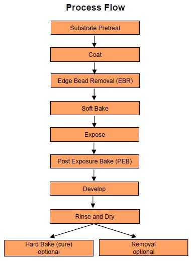
5 Photolithography (Cont.) 5

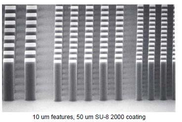
6 Positive & Negative Photoresists A photoresist is a light sensitive material used in several industrial processes, such as photolithography and photoengraving to form a patterned coating on a surface. Shipley 1813 SU
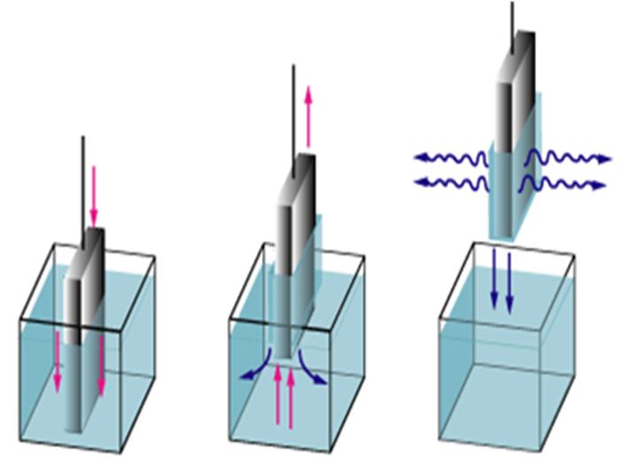
7 Photoresist Film Coating Spin coating Dip coating Spray coating 7

8 Positive & Negative Photomasks A photomask is an opaque plate with holes or transparencies that allow light to shine through in a defined pattern. Positive mask Negative mask Types of masks: Chrome Glass, Transparency, Metal, etc. 8
9 Contact Between a Photomask and a Photoresist 9


10 Photomask Design Chrome mask When feature size is necessarily small and resolution is critical, your best bet may be to go with a metal mask. Most mask providers will print a 5x5 inch chromeon glass mask. The cost will be similar whether you order one or ten devices on a single mask, so you may as well fill up the whole area. Their machinery is capable of ~1 μm features, so be sure your smallest dimension does not exceed this limit. Transparency Mask Laser printed mask on a transparency. The resolution is dependent on the dpi of a laser printer. Typically a few microns is the minimum resolution that can be done. Compared with a chrome mask, it is cheap and good for rapid prototyping, but not very longlasting. 10
11 Photomask Design Most providers accept dwg, gds, and some other CAD files such as those generated in AutoCAD. It is recommended that you begin with a template resembling the ones below. A 10mm buffer area around the perimeter of the mask is needed. (A) A 5x5 inch mask with useable area overlay, (B) the recommended template for four 2.5x2.5 inch masks. 11


12 Format of Photomask Clear Field Right Reading Up Clear Field Right Reading Down Dark Field Right Reading Up Dark Field Right Reading Down 12

13 Standard Patterning Substrate Film deposition Photolithography Etching Photoresist removal Patterns 13

14 Lift off 14
15 Introduction of Soft Lithography Soft lithography refers to a family of techniques for fabricating or replicating structures using "elastomeric stamps, molds, and conformable photomasks. It is called "soft" because it uses elastomeric materials, most notably PDMS Soft lithography has some unique advantages over other forms of lithography : Lower cost than traditional photolithography in mass production Well suited for applications in biotechnology Well suited for applications in plastic electronics Well suited for applications involving large or nonplanar (nonflat) surfaces More pattern transferring methods than traditional lithography techniques (more "ink" options) Does not need a photo reactive surface to create a nanostructure Smaller details than photolithography in laboratory settings (~30 nm vs ~100 nm). The resolution depends on the mask used and can reach 6 nm. 15


16 Soft Lithography: Polydimethylsiloxane Sylgard 184 Cure agent 1:10 mixing ratio 16
17 Physical and Chemical Properties of PDMS (Cooper et al., 2001) 17


18 Features of PDMS Nano resolution Soft, transparent elastomer 18
 Reactive oxygen radicals")
 and")
.")
19 Features of PDMS (Cont.) Reactive oxygen radicals are attacking the methyl groups (Si CH3) and substitute them by silanol groups (Si OH). Surface treatment Porous material 19


20 Features of PDMS (Cont.) mold Reusable mold Mass production 20
21 Rapid Prototyping Procedure 21
22 Comparison of Photolithography to Soft lithography 22
23 Deformation and Distortion Delamarche et al. showed that the aspect ratios (l/h) of the relief structures on PDMS surfaces had to be between about 0.2 and 2 in order to obtain defect free stamps. 23
24 Applications of PDMS Mechatronics Optics Microfluidics Biotechnology 24


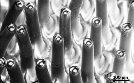
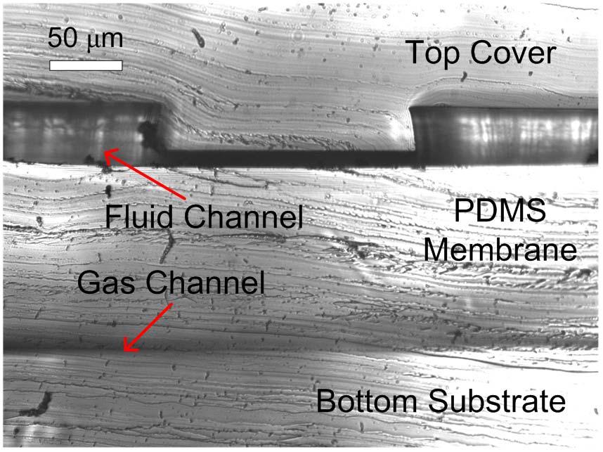
25 Microstructures : Microchannels Diagram of the coring process and the interconnect fabrication method 25


26 Moving Parts : Valves & Peristaltic Pump 26
27 Three Valve Peristaltic Pump Phase : The complete on-off action in a valve. Pump Frequency : The number of strokes generated by a pump in a second. Advantages: 1. Programmable (bi directional, flow rate, sequence) 2. Ease of use 3. On chip integration Disadvantages: 1. Pulsatile flow 2. A transient perturbation into flow 27
28 Pump Sequences Diodicity (D) : Oscillation number (O) : # of D 1 u t cycle cycle Q dt Q b f dt 0 u 0 Output efficiency (η) : vol cycle 3V Qdt valve 4-phase 5-phase 6-phase D O η Chuang, H.S., Amin, A.M., Wereley, S.T., Thottethodi, M., Vijaykumar, T.N., Jacobson, S.C., µtas 2008, Paper#0154 (San diego, CA), Oct.12 16,

29 How a Peristaltic Pump Works for Mixing 29
30 Gas Purge Valves Goal: Purge gas and align liquid slugs for the proposed mixing procedure. Surface tension enabled (ST) valve 2( h w) cos( ) P d hw Gas permeation enabled (GP) valve dv PA( p p T 76 1) dt b P atm Liquid Fluid Residual Air pressure vacuum Valve closed For low pressure (<5.5 kpa) GP Valve For high pressure (>5.5 kpa) Chuang, H.S., Amin, A.M., Wereley, S.T., Thottethodi, M., Vijaykumar, T.N., Jacobson, S.C., US provisional patent# ,


![[s] Position [ m] 2000 1500 1000 next](/docs-images/84/90813611/images/31-5.jpg "to the vent far from the vent 500 0 0")

![m] 1800 1600 1400 1200 1000 800 600](/docs-images/84/90813611/images/31-7.jpg "400 200 0 0 20 40 60 80 100 Time")
31 Gas Permeation Valve Position [ m] w/ a pump 900 w/o a pump Time Elapsed [s] Position [ m] next to the vent far from the vent Time Elapsed [s] Length of Residual Air [ m] Time Elapsed [s] exp. theo. 31


32 Application : Mixing Table Mixing efficiency at different mixing cycles. 0 th cycle 1 st 2 nd 3 rd 4 th σ 41.88% 94.28%

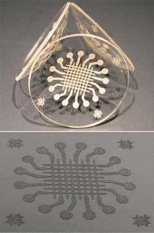
33 Conductive PDMS Ag+PDMS C+PDMS (Niu et al., 2007) 33


34 Fabrication : Rapid Patterning (Chuang et al, 2008) 34

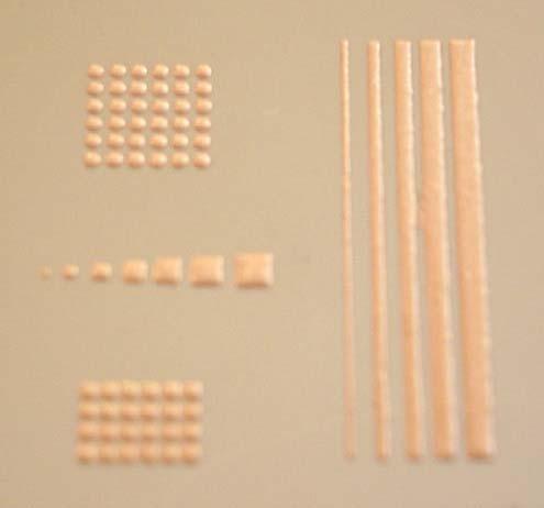
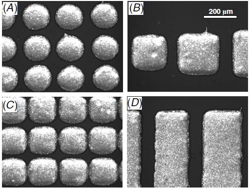
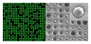
35 Results of Rapid Patterning 35

36 Results of Rapid Patterning (Cont.) 36


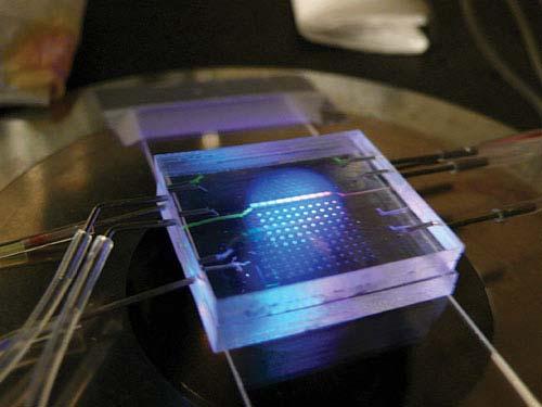
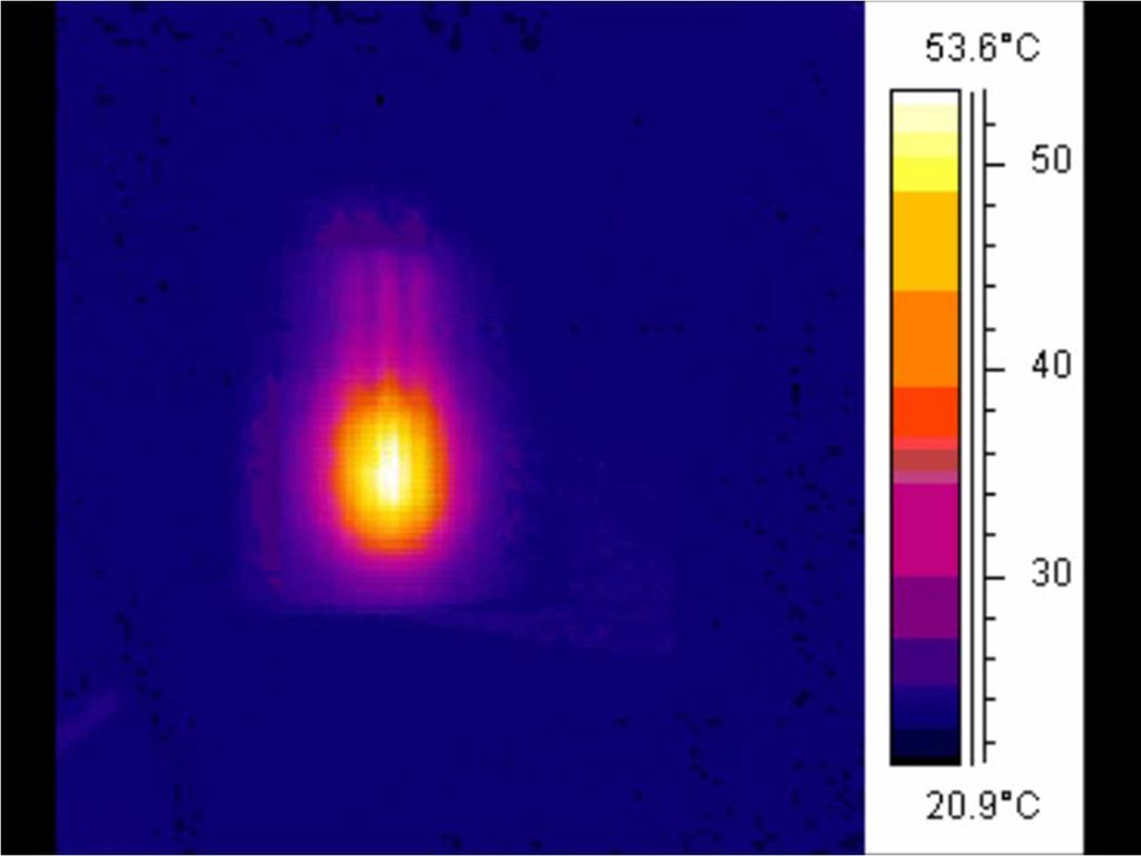
37 A Microheater & a Temperature Sensor 100 C 70 C 10.1 Ω, 210 mw, 92 C 37
38 38