29 September 2009 Chapter 6: Mechanical Properties of Metals
|
|
|
- Kristina Dorcas Wiggins
- 5 years ago
- Views:
Transcription

1 29 September 2009 Chapter 6: Mechanical Properties of Metals
2 What do I need to know Important Mechanical Properties (NB!! UNITS) Stress and Strain Hardness and Brittleness Failure Toughness Fracture Mechanics Fatigue Toughness Creep
3 Stress= External force per unit area Force PERPENDICULAR AWAY from area (Tensile Stress) Force PARALLEL ONTO area (Shear) Force PPERPENDICULAR ONTO area (Compressive Stress) Strain= Effective % elongation due to applied Force Elastic NON-PERMANENT (Rubber-band) Plastic PERMANENT (Prestik)
4 Differentiate between ENGINEERING STRESS and TRUE STRESS: σing = F/Ao (N/mm2) or (MPa) σt = F/Af (N/mm2) or (MPa) (NB! Area may be circular, rectangular or square) (NB! If the applied force is in the same direction as gravity, F = W = mg) Differentiate between ENGINEERING STRAIN and TRUE STRAIN ε = L / Lo with L = Lf - Lo(%) or (Fraction) εt = ln(li/lo)

 εt =")
5 Relationship between TRUE σ ε and ENGINEERING σ ε σt = σ(1+ ε) εt = ln(1 + ε)
 Modulus of Resilliance (J/m3) Impact Strenght (J/m3) Ductility(%) Elongation(%) Reduction in Area(%)")
6 Information obtained from a Stress-Strain graph Yield Strength (MPa) Ultimate Tensile Strenght (MPa) Fracture Strength(MPa) Young se Modulus (GPa) Modulus of Resilliance (J/m3) Impact Strenght (J/m3) Ductility(%) Elongation(%) Reduction in Area(%)
7 Young se Modulus E = σ/ε (GPa) NB! ONLY IN THE ELASTIC REGION Modulus of Resilliance ELASTIC Energy that can be absorbed Ur = 0.5(σy.ε) (Area of the Triangle) Impact Strenght TOTAL Energy absorbed at failure Ductility Expressed as %ε or %Z = (Ao Af)/Ao x 100 Remember that the volume of a test specimen stays constant, THUS: Ao.Lo = Af.Lf
8 Force (N) Length (mm) , , , , , , , , , , , , , The table shows the measurements taken during a tensile test. The specimen had an original diameter of 12.8mm. Calculate the following: Modulus of elasticity (62.5 GPa) The tensile strength of the sample (370 MPa) Approximate ductility (16% EL) Modulus of Resilience (6.5 x10⁵ J/m3)
9 Shear is a function of TORSION or TORQUE applied to the component τ = Fo /A (MPa) γ = w/lo = tanθ (% or Fraction) τ = G γ (G = Shearmodulus, GPa)
10 Hardness is a function of materials to resist plastic deformation, and considered a nondestructive testing method Brinell Test Load/Indentation area (kg/mm2) Load 50kg, Indenter Diameter = 6.35mm Vickers Test Rockwel Test Rf = 60kg Load, 1/16 Inch Steel ball indenter Rb = 100kg Load, 1/16 Inch Steel ball indenter Rc = 150kg Load, Diamond Cone indenter


11 Hardness and brittleness of metals are DIRECTLY PROPORTIONAL to each other The harder a metal/alloy, the more brittle and less ductile the component will be.
12 Failure occurs due to CRACK PROPAGATION PERPENDICULAR to the applied σ Ductile failure Slow crack propagation Plastic deformation area increase High energy absorption before failure occurs Brittle failure High crack propagation rate due to low energy requirements for a crack to propagate Very little plastic deformation is required for crack propagation


13 Brittle failure (Bright, rough surface) Ductile failure (Dull, smooth surface)
14 Toughness is a material property defined as the amount of ENERGY that is absorbed before failure, and thus the resistance against crack propagation Toughness may be determined through the CHARPY or IZOD impact strength machine, and is measured in J Toughness is influenced by CRYSTALSTRUCTURE and TEMPERATURE at which the test is done, as well as the NOTCH in the test specimen.
15 Brittle-transition-temperature (BTT) Marks the transition between brittle and ductile failure BTT may be determined with 2 methods 1. Temperature at which the impact strength is 30J 2. Temperature where the AVERAGE IMPACT STRENGTH is measured (Max IS + Min IS)/2
16 Stress Concentration Increase in the local stress close to the crack σlocal = σapplied.y πc Internal crack: c = 2c Surface crack: c = c Mode 1 of Failure(Tensile test) K1 = σlocal= σapplied.y πc Fracture toughness Absorbed energy due to crack propagation that causes failure Efailure = 2γA (γ = Specific Surface Energy) Energy obtained from Modulus of Resiliance Critical stress that may be applied before failure is: σc = (2Eγ/ π c)0.5 AND K1c = Yσc πc
17 A component has a fracture toughness of 77MPa m and σys of 1400MPa. A NDT test is used to measure crack lengths greater than 4mm. Will the component fail the test if a stress equal to half of the yield stress is applied? (a=3.85mm)
18 A component has the following properties: KIC = 35MPa m σ = 250MPa Internal Crack length= 2mm Will the component fail if a stress of 325MPa is applied and the maximum internal crack length that may be measured is 1mm? The component won t fail
/2 σr = (σmax σmin) σa = (σmax")
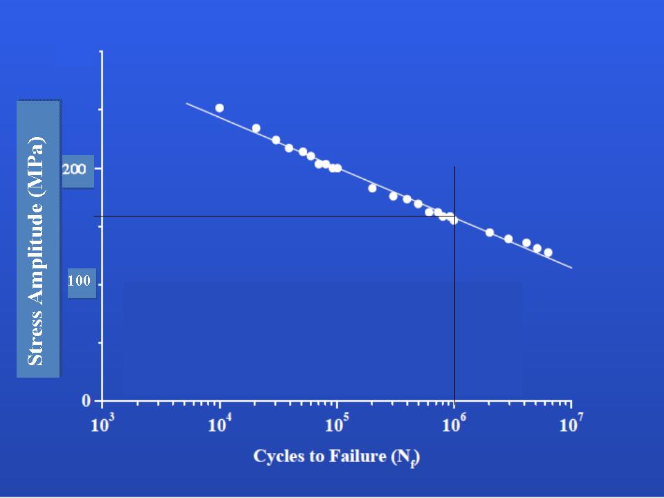
19 Fatigue failure occurs when a crack propagates slowly due to cyclic stresses and time Cyclic stresses alternate between compressive and tensile, thus σm = (σmax + σmin)/2 σr = (σmax σmin) σa = (σmax σmin)/2


20 Basquin s Law: ΔσNfb= C1 σm = 0 MPa or stress amplitude is constant Goodman s Law: Δσσm = Δσσo[1 σm/ σts] Two types of cyclic stresses 1. Average stress σm 0 MPa 2. σo = 0 MPa Miner s Law: Cyclic stresses with CHANGING amplitude
21 A 4x6mm rectangular Aluminum 2014-T6 specimen is subjected to cyclic stresses. Determine the maximum and minimum forces that may be applied to achieve a fatigue life of 1x10⁶ cycles. Take the mean cyclic stress as 40MPa. (Fmx=11 000N) (Fmin=-3 500N)
22

23 Stress Concentrations Surface Condition Harder surface higher resistance to fatigue failure Carburization, Nitriding Environmental Conditions Surface Finish Rough surface more stress concentrations Machined> Grinded> Polished Corrosive environments increases the possibility of stress corrosion cracking NB! SCC is NOT a form of corrosion; corrosion of stress concentration point lowers the fatigue life of materials.
24 Creep occurs when strain is influenced by time and temperature plastic deformation may occur when σapplied < σys Influence of Stress εss = Bσn log εss = logb + nlog σ Influence of Temperature εss = C1e-Q/RT Steady State Creep (Primary) εss = C2 σn e-q/rt Creep failure Grainboundaries slip and creep cavitation εss tf= C3

25 Creep Mechanisms Nabarro-Herring / Diffusionflow Creep - n = 1 Compressive stress (empty vacancies diffuse to grain boundaries) and Tensile stress (Atoms diffuse to empty vacancies) Deforms the material and thus the grains elongate in the direction of tensile stress direction. Due to this phenomenon, SMALL Grains are detrimental for resistance to creep. Powerlaw Creep n = 3-8 Mechanism is equivalent to the accumulation of dislocations Migration of dislocations and grains to grains and grainboundaries.
26 Complete the Table: Q=330kJ/mol Temp ( C) Єss/hr x tf (hr) x10-3 Tf = h Ɛss=1.48x10⁻³/hr
27 What type of creep occurs if the creep rate is 9.4x10⁻³/hr at a temperature of 1000 C Power Law Creep