CE 240 Soil Mechanics & Foundations Lecture Shear Strength of Soil II (Das, Ch. 11)
|
|
|
- Marianna Betty Atkinson
- 5 years ago
- Views:
Transcription
1 CE 240 Soil Mechanics & Foundations Lecture 11.2 Shear Strength of Soil II (Das, Ch. 11)
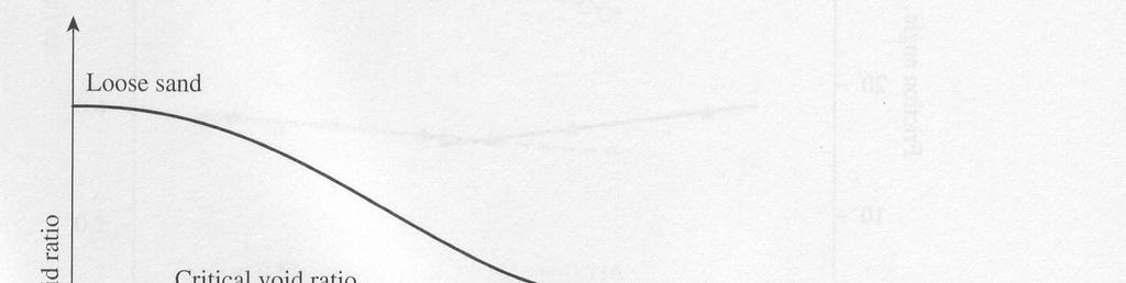
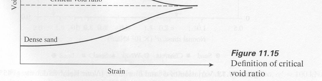
2 Direct shear test Class Outlines Introduction Critical void ratio Triaxial shear test Introduction Procedure & calculation Critical void ratio
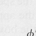
3 Mohr-Coulomb shear failure criterion σ 1 τ σ n σ 3 σ 3 τ f Failed Zone (σ, τ) φ τ f =c +µ σ n σ 1 c σ 3 σ ff φ 2θ σ 1 σ
4 Direct Shear Test Direct shear test is Quick and Inexpensive Shortcoming is that it fails the soil on a designated plane which may not be the weakest one Used to determine the shear strength of both cohesive as well as non-cohesive soils ASTM D 3080
5 Direct Shear Test (cont.) The test equipment consists of a metal box in which the soil specimen is placed The box is split horizontally into two halves Vertical force (normal stress) is applied through a metal platen Shear force is applied by moving one half of the box relative to the other to cause failure in the soil specimen Shear stress σ 3 Soil Normal stress σ n
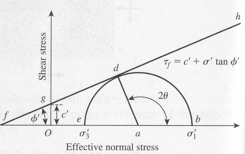
6 Direct Shear Test
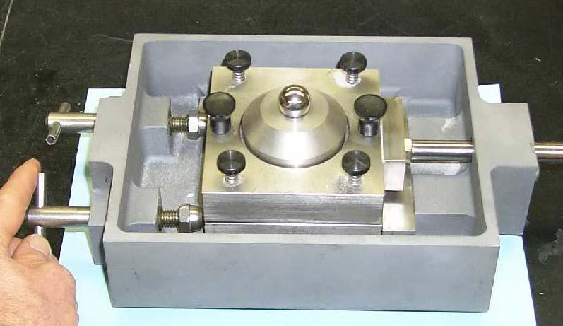
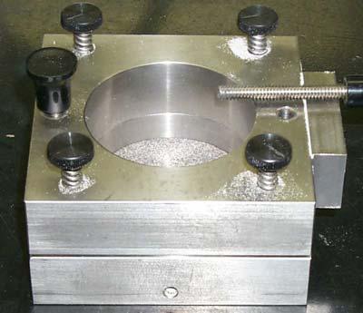
7
8 Calculations 1. Determine the dry unit weight, γ d 2. Calculate the void ratio, e e = Gsγ γ d w 1 3. Calculate the normal stress & shear stress N σ = ; τ = A V A
9 Figures Peak Stress Shear stress, s s 3 s 2 s 1 N 3 = 30 kg N 2 = 20 kg N 1 = 10 kg Horizontal displacement, H
10 Figures (cont) Shear Stress, s (psf) C (σ 1,s 1 ) (σ 2,s 2 ) φ (σ 3,s 3 ) Normal Stress σ, psf
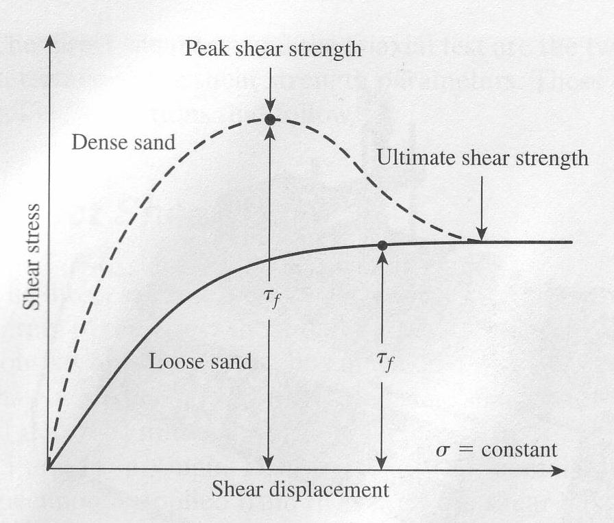
11 Direct Shear Test Data Shear stress Peak Strength Residual Strength
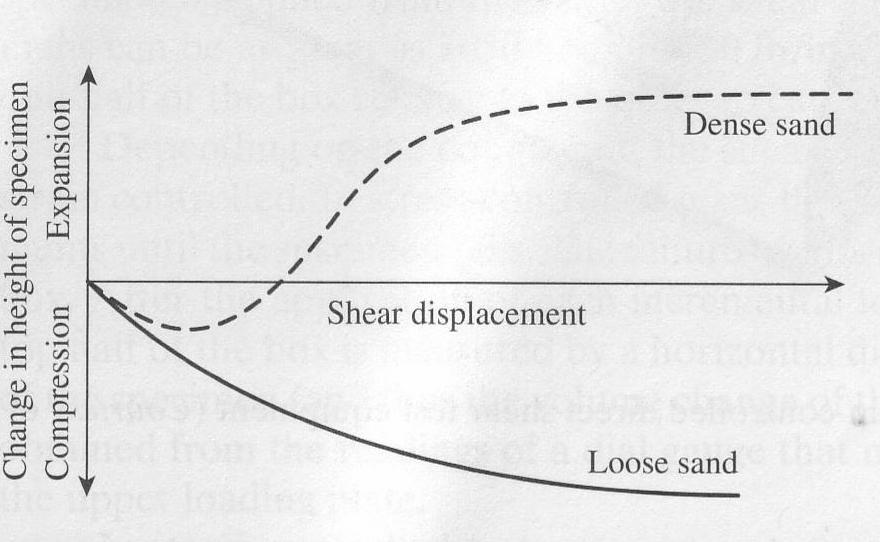
12 Direct Shear Test Data: Volume change H
13


14
15 Triaxial Shear Test Developed by Casagrande in an attempt to overcome some of the serious disadvantages of the direct shear test. Advantages over DST More Versatile Drainage can be well controlled There is no rotation of the principal stresses like the direct shear test Also the failure plane can occur anywhere
16 Triaxial Test: Increase the normal stress in one direction σ 1 major principle stress σ n σ 3 σ 3 τ f Minor principle stress Confining stress σ 1
17
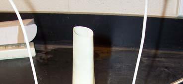
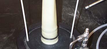
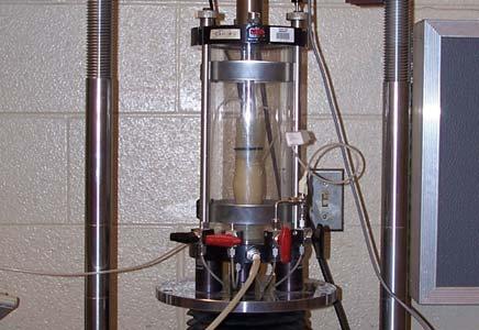
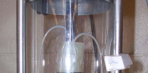
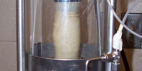
18 Principles of the Triaxial Compression (TC) Test The triaxial compression test is used to measure the shear strength of a soil under controlled drainage conditions A cylindrical specimen of soil is encased and subjected to a confining fluid/air pressure and then loaded axially to failure. The test is called "triaxial" because the three principal stresses are assumed to be known and are controlled.
19 Principles of the TC Test During shear, the major principal stress, σ 1 is equal to the applied axial stress ( σ = P/A) plus the chamber (confining) pressure, σ 3 The applied axial stress, σ 1 - σ 3 is termed the "principal stress difference" or sometimes the "deviatory stress The intermediate principal stress, σ 2 and the minor principal stress, σ 3 are identical in the test, and are equal to the confining or chamber pressure σ 1 = σ + σ3 σ σ 2 = σ 3 σ 1 σ 3 σ 3


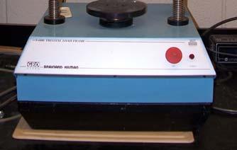
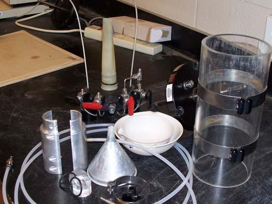
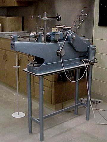
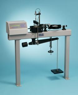
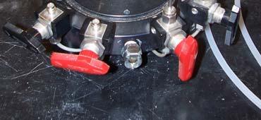
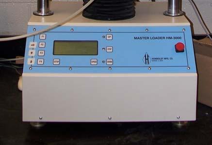
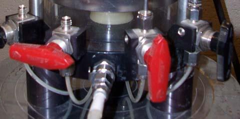
20 Triaxial Test Equipment The Cell (Chamber) Loading Frame Control Panel

21
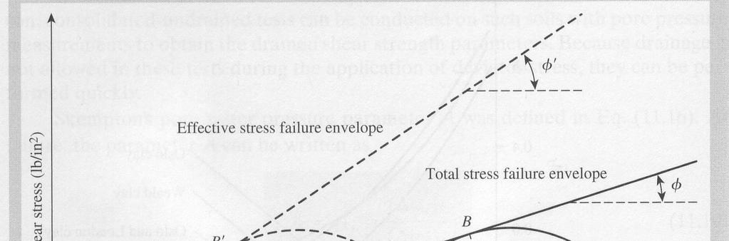
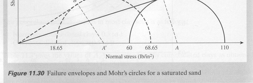
22 Soil Shear Strength under Drained and Undrained Conditions. Drained conditions occur when rate at which loads are applied are slow compared to rates at which soil material can drain (k - dependent) Sands drain fast; therefore under most loading conditions drained conditions exist in sands Exceptions: pile driving, earthquake loading in fine sands
23 Soil Shear Strength under Drained and Undrained Conditions. In clays, drainage does not occur quickly; therefore excess pore water pressure does not dissipate quickly Therefore, in clays the short-term shear strength may correspond to undrained conditions Even in clays, long-term shear strength is estimated assuming drained conditions


24 Loose sand and norm. consolidated clay dense sand and overconsolidated clay
25 Types of Tests There are three types of tests: 1. Unconsolidated-undrained (UU or Q) Test 2. Consolidated-undrained (CU or R) Test 3. Consolidated-drained (CD or S) Test
26 Unconsolidated-undrained Test This test is also called the quick test. σ 3 and σ are applied fast so the soil does not have time to settle or consolidate. The test is performed with the drain valve closed for all phases of the test. (Water is not allowed to drain) UU test simulates short term shear strength for cohesive soils. For this test, φ = φ = 0 s = c u = Su = (σ 1 -σ 3 )/2 = (σ 1 -σ 3 )/2
27 UU Test Results σ σ 1 3 ( ) 2
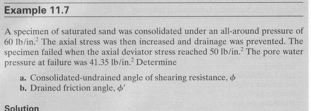
28 Consolidated-undrained Test Apply σ 3 and wait until the soil consolidates Drainage valves open during consolidation phase but closed during the shearing phase (Drainage and consolidation is allowed to take place during the application of the confining pressure σ 3 ) Loading does not commence until the sample ceases to drain (or consolidate). This test can simulates long term as well as short term shear strength for cohesive soils if pore water pressure is measured during the shearing phase For this Test, c T c and φ T = φ From this test we obtain; c, φ and u (Effective stress) c T, φ T (Total stress)


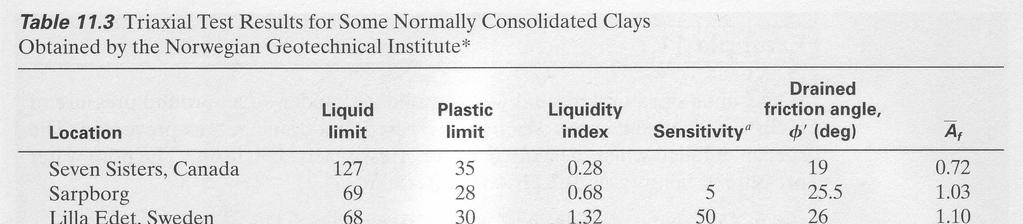
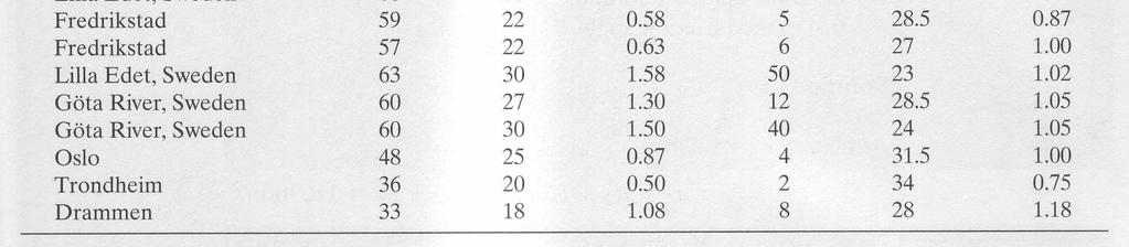
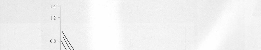
29 Skempton pore pressure parameter
30
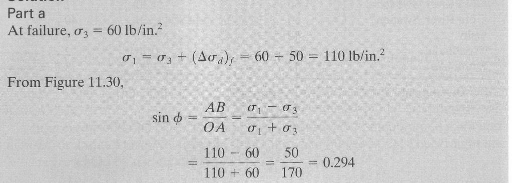
31 c.
32
 f ( σ d")

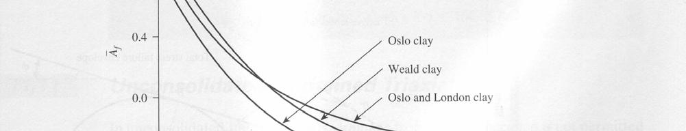
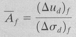
33 Part c Af = ( ud ) f ( σ d ) f = =
34 Consolidated-drained Test Also called slow test. Drainage valves OPEN during consolidation as well as shearing phases. Complete sample drainage is achieved prior to application of the vertical load. The load is applied at such a slow strain rate that particle readjustments in the specimen do not induce any excess pore pressure. (can take up to 2 weeks) Since there is no excess pore pressure total stresses will equal effective stresses. This test simulates long term shear strength for cohesive soils.
35 CD Test Results
36 Triaxial Test on Sand Conduct a CD test on sand. Soil specimens will be loaded to failure under 3 different confining pressures; 15, 30 and 45 psi Failure will be defined as the peak or 3 maximum value of principal stress difference reached. ASTM D 2850
 P A c A 0")
37 Test Results and Calculations ε = A c = σ = l l 0 ( 1 ε ) P A c A 0
38 Determining σ 1 σ = 2700 psf σ 32 = 1000 psf σ 1 = σ = 1 σ + σ = 3700 psf
39 Mohr s Circles σ 1 = 3700 psf τ σ 3 = 1000 psf σ 3 = 1000 psf σ σ 1= 3700 psf
40 Triaxial Test on Sand - Figures σ c σ b σ a 45 psi 30 psi 15 psi
41 Reading Assignment: Das, Ch. 11 HW: Problem 11.11, 11.15