Ultrasonic Machining (USM)
|
|
|
- Justin Owens
- 5 years ago
- Views:
Transcription
1 Ultrasonic Machining (USM) 1
2 Introduction Ultrasonic machining (USM) is the removal of hard and brittle materials using an axially oscillating tool at ultrasonic frequencies [18 20 khz] During that oscillation, the abrasive slurry of B 4 C or SiC is continuously fed into the machining zone between a soft tool (brass or steel) and the workpiece. The abrasive particles are, therefore, hammered into the workpiece surface and cause chipping of fine particles from it. The oscillating tool, at amplitudes ranging from 10 to 40 µm, imposes a static pressure on the abrasive grains and feeds down as the material is removed to form the required tool shape. Balamuth first discovered USM in 1945 during ultrasonic grinding of abrasive powders. The industrial applications began in the 1950s when the new machine tools appeared. USM is characterized by the absence of any deleterious effect on the metallic structure of the workpiece material. 2
3 USM - Components 3
4 Machining System The machining system of USM is composed mainly from the magnetostrictor, concentrator, tool and slurry feeding arrangement. The magnetostrictor is energized at the ultrasonic frequency and produces small-amplitude vibrations. Such a small vibration is amplified using the constrictor (mechanical amplifier) that holds the tool. The abrasive slurry is pumped between the oscillating tool and the brittle workpiece. A static pressure is applied in the tool-workpiece interface that maintains the abrasive slurry. 4
5 Main Elements of an USM 5
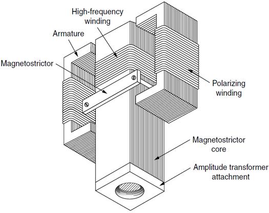
6 Magnetostrictor 6
7 Magnetostrictor It has a high-frequency winding wound on a magnetostrictor core and a special polarizing winding around an armature. Magnetostriction is a property of ferromagnetic materials that causes them to change their shape or dimensions during the process of magnetization. The variation of material's magnetization due to the applied magnetic field changes the magnetostrictive strain until reaching its saturation value, λ. The effect was first identified in 1842 by James Joule at Manchester when observing a sample of nickel. Magnetostrictive materials can convert magnetic energy into kinetic energy, or the reverse, and are used to build actuators and sensors. 7
8 Magnetostrictor The property (magnetorestriction) can be quantified by a factor called magnetostrictive coefficient or coefficient of magnetostriction elongation. It is the fractional change in length as the magnetization of the material increases from zero to the saturation value. The effect is responsible for the familiar "electric hum which can be heard near transformers. This effect is used to oscillate the USM tool at ultrasonic frequencies (18 to 20 khz). The USM tool is mounted at the end of a magnetostrictor. The coefficient of magnetostriction elongation is ; where lis the incremental length and l is the original length of the magnetostrictor core. Materials having high coefficient of magnetostrictive elongation are recommended to be used for a magnetostrictor. 8
9 Magnetostrictor The elongation is independent of the sign of the magnetic field. The variation of the magnetic field intensity changes in elongation at double the frequency (2f ). Changes in elongation are not sinusoidal (full wave rectified). If the transducer is magnetized with a direct current, sinusoidal changes in elongation are obtained. 9
10 Magnetic Amplifier The elongation obtained at the resonance frequency (f r ) using a magnetostrictor of particular length is usually to 0.1 µm. This is too small for practical machining applications. The vibration amplitude is increased by fitting an amplifier (acoustic horn) into the output end of the magnetostrictor. Larger amplitudes, typically 40 to 50 µm, are found to be suitable for practical applications. Depending on the final amplitude required, the amplitude amplification can be achieved by one or more acoustic horns. 10
11 Magnetic Amplifier The choice of the shape of the acoustic horn controls the final amplitude. Five acoustic horns (cylindrical, stepped, exponential, hyperbolic cosine, and conical horns) have been reported by Youssef (1976). Exponential and stepped types are frequently used. Because they are easily designed and produced compared to the conical and hyperbolic horns. Aluminum bronze and marine bronze are cheap with high fatigue strengths of 185 and 150 MN/m 2 respectively. Drawbacks of magnetostrictive transducer: (a) high losses (b) low efficiency (55 %) (c) heating up and the need for cooling. Higher efficiencies (90 95 %) are possible by using piezoelectric transformers in modern USM machines. 11
12 Tools Tool tips must have high wear resistance and fatigue strength. For machining glass and tungsten carbide, copper and chromium silver steel tools are recommended. Silver and chromium nickel steel are used for machining sintered carbides. During USM, tools are fed toward, and held against, the workpiece by means of a static pressure that has to overcome the cutting resistance at the interface of the tool and workpiece. Different tool feed mechanisms are available that utilize: Pneumatic Periodic switching of a stepping motor or solenoid Compact spring-loaded system Counterweight techniques. 12
13 Abrasive Slurry Abrasive slurry is usually composed of 50 vol. % of fine abrasive grains and 50 vol.% of water. Abrasive grain sizes: grit number. Abrasive particles used: (a) Boron carbide (B 4 C) (b) Aluminum oxide (Al 2 O 3 ) or (c) Silicon carbide (SiC). The abrasive slurry is circulated between the oscillating tool and workpiece. Under the effect of the static feed force and the ultrasonic vibration, the abrasive particles are hammered into the workpiece surface causing mechanical chipping of minute particles. The slurry is pumped through a nozzle close to the tool-workpiece interface at a rate of 25 L/min. As machining progresses, the slurry becomes less effective as the particles wear and break down. The expected life ranges from 150 to 200 h of ultrasonic exposure. 13
14 Abrasive Slurry The slurry is continuously fed to the machining zone in order to ensure efficient flushing of debris and keeps the machining area cool. The performance of USM depends on the manner in which the slurry is fed to the cutting zone. The different slurry feeding arrangements: 14
15 Material Removal Process Material removal mechanism of USM involves three distinct actions: 1. Mechanical abrasion by localized direct hammering of the abrasive grains stuck between the vibrating tool and adjacent work surface. 2. The microchipping by free impacts of particles that fly across the machining gap and strike the workpiece at random locations. 3. The work surface erosion by cavitation in the slurry stream. 15
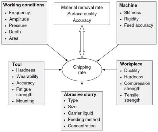
16 Material Removal Process The relative contribution of the cavitation effect is reported to be less than 5 percent of the total material removed. The dominant mechanism involved in USM of all materials is direct hammering. Soft and elastic materials like mild steel are often plastically deformed first and are later removed at a lower rate. In case of hard and brittle materials such as glass, the machining rate is high and the role played by free impact can also be noticed. When machining porous materials such as graphite, the mechanism of erosion is introduced. The rate of material removal, in USM, depends, on the frequency of tool vibration, static pressure, the size of the machined area, and the abrasive and workpiece material. MRR and machinability by USM depends on the brittleness criterion which is the ratio of shearing to breaking strength of a material. 16
17 Material Removal Rate 17
18 USM Performance 18
19 Factors affecting MRR 1. Tool Oscillation or Vibration Amplitude & Frequency Amplitude of the tool oscillation has the greatest effect of all the process variables. MRR increases with a rise in the tool vibration amplitude. Vibration amplitude determines the velocity of the abrasive particles at the interface between the tool and workpiece. Under such circumstances the kinetic energy rises, at larger amplitudes, which enhances the mechanical chipping action and consequently increases the MRR. A greater vibration amplitude may lead to the occurrence of splashing, which causes a reduction of the number of active abrasive grains and results in a decrease in the MRR. 19
20 Factors affecting MRR Contd. Tool Oscillation Contd. According to Kaczmarek (1976) with regard to the range of grain sizes used in practice, the amplitude of oscillation varies within the limits of 0.04 to 0.08 mm. The increase of feed force induces greater chipping forces by each grain, which raises the overall removal rate. McGeough (1988) reported that the increase in vibration frequency reduces the removal rate. This trend may be related to the small chipping time allowed for each grain such that a lower chipping action prevails and causing a decrease in the removal rate. 20
21 Factors affecting MRR Contd. 2. Abrasive Grains Both the grain size and the vibration amplitude have a similar effect on the removal rate. According to McGeough (1988), MRR rises at greater grain sizes until the size reaches the vibration amplitude, at which stage, the MRR decreases. When the grain size is large compared to the vibration amplitude, there is a difficulty of abrasive renewal. Because of its higher hardness, B 4 C achieves higher removal rates than silicon carbide (SiC) when machining glass. The MRR obtained with silicon carbide is about 15 % lower when machining glass, 33 % lower for tool steel, and about 35 % lower for sintered carbide. 21
22 Factors affecting MRR Contd. 2. Abrasive Grains Contd. Water is commonly used as the abrasive carrying liquid for the abrasive slurry while benzene, glycerol, and oils are alternatives. The increase of slurry viscosity reduces the removal rate. The improved flow of slurry results in an enhanced machining rate. In practice a volumetric concentration of about 30 to 35 percent of abrasives is recommended. A change of concentration occurs during machining as a result of the abrasive dust settling on the machine table. The actual concentration should, therefore, be checked at certain time intervals. The increase of abrasive concentration up to 40 % enhances MRR. More cutting edges become available in the machining zone, which raises the chipping rate and consequently the overall removal rate. 22
23 Factors affecting MRR Contd. 3. Workpiece Impact Hardness MRR is affected by the ratio of tool hardness to workpiece hardness. In this regard, the higher the ratio, the lower will be MRR. For this reason soft and tough materials are recommended for USM tools. 4. Tool Shape Increase in tool area - decreases the machining rate; due to inadequate distribution of abrasive slurry over the entire area. McGeough (1988) reported that, for the same machining area, a narrow rectangular shape yields a higher machining rate than a square shape. Rise in static pressure - enhances MRR up to a limiting condition, beyond which no further increase occurs. Reason - disturbance in the tool oscillation at higher forces where lateral vibrations are expected. 23
24 Factors affecting MRR Contd. 4. Tool Shape Contd. According to Kaczmarek (1976), at pressures lower than the optimum, the force pressing the grains into the material is too small and the volume removed by a particular grain diminishes. Measurements also showed a decrease in MRR with an increase in the hole depth. Reason - deeper the tool reaches, the more difficult and slower is the exchange of abrasives from underneath the tool. 24
25 Dimensional Accuracy Accuracy (oversize, conicity, out of roundness) - affected by Side wear of the tool Abrasive wear Inaccurate feed of the tool holder Form error of the tool Unsteady and uneven supply of abrasive slurry Overcut Holes accuracy is measured through overcut (oversize). Hole oversize measures the difference between the hole diameter, measured at the top surface, and the tool diameter. Side gap between tool and hole is necessary to enable abrasive flow. Hence, grain size of the abrasives represents the main factor, which affects the overcut produced.
26 Dimensional Accuracy Contd. Overcut is considered to be about 2-4 times greater than the mean grain size when machining glass and tungsten carbide. It is about 3 times greater than the mean grain size of B 4 C. However, the magnitude of overcut depends on many other process variables (type of workpiece material and the method of tool feed). In general, USM accuracy levels are limited to mm. Conicity (non-parallel sides) Overcut is usually greater at the entry side than at the exit. Reason - cumulative abrasion effect of fresh and sharp grain particles. As a result, a hole conicity of ~ 0.2 arises when drilling a hole of φ 20 mm and a depth of 10 mm in graphite.
27 Dimensional Accuracy Contd. The conicity may be reduced by Direct injection of abrasive slurry into the machining zone. Use of tools having negatively tapering walls. Use of high static pressure that produces finer abrasives, which in turn reduces the tool wear. Use of wear-resistant tool materials. Use of an undersized tool in the first cut and a final tool of the required size, which will cut faster and reduce the conicity. Out of roundness Out of roundness arises by the lateral vibrations of the tool. Such vibrations - due to out of perpendicularity of tool face and centerline. Also due to misalignment in the acoustic parts of the machine. Typical values - ~ µm for glass and µm for graphite.
28 Surface Quality Surface finish - closely related to the machining rate in USM. Table shows the relationship between grit number and grit size. Larger the grit size, faster the cutting rate but surface finish is poor. Surface finish of 0.38 to 0.25 µm can be expected using abrasives of grit number 240.
29 Surface Quality Contd. However, other factors such as tool surface, amplitude of tool vibration, and material being machined also affect the surface finish. Larger the grit size (smaller grain size), the surface will be smooth. The larger chipping marks formed on brittle materials create rougher surfaces than that obtained in case of hard alloy steel. Amplitude of tool oscillation has a smaller effect on the surface finish. As the amplitude is raised, individual grains are pressed further into the workpiece surface and cause deeper craters a rough surface. Static pressure has a little effect on the surface finish. Smoother surfaces can also be obtained by using low viscosity liquid. Surface irregularities on sidewall are larger than those on the bottom. Reason - Sidewalls are scratched by abrasive grains. Cavitation damage occurs when the particles penetrate deeper. Under such circumstances, it is difficult to replenish the slurry in these deeper regions and thus a rougher surface is produced.
30 Applications of USM USM should be applied for shallow cavities cut in hard and brittle materials having a surface area less than 1000 mm 2. Drilling and coring.
31 Applications of USM Contd. Fig. - Modified version of USM - tool bit is rotated against the workpiece in a similar fashion to conventional drilling. The process is, therefore, called Rotary Ultrasonic Machining (RUM). Cruz et al. (1995) used such a process for machining non-metallic materials such as glass, alumina, ceramic, ferrite, quartz, zirconium oxide, ruby, sapphire, beryllium oxide, and some composite materials. RUM ensures high removal rates, lower tool pressures for delicate parts, improved deep hole drilling, less breakout or through holes, and no core seizing during core drilling of the cavity. Deep holes require more time as the rate of machining decreases with the depth of penetration. This is due to the difficulty in maintaining a continuous supply of new slurry at the tool face. Generally a depth-to-diameter ratio of 2.5 is achievable by RUM.
32 Applications of USM Contd. Ultrasonic sinking and contour machining


33 Applications of USM Contd. During USM sinking, material removal is difficult for depth > 5 to 7 mm. Under such conditions, the removal of abrasives at the interface becomes difficult and hence the material removal process is impossible. Moreover, manufacturing of such a tool is generally complex and costly. Contouring USM - simple tools that are moved along the contour required. Fig. shows holes and contours machined using a USM contour machining. Silicon nitride turbine blades (sinking) Acceleration lever and holes (contour USM)

34 Applications of USM Contd. Production of EDM Electrodes Gilmore (1995) used USM to produce graphite EDM electrodes (Fig.). Typical machining speeds, in graphite range from 40 to 140 mm/min. Surface roughness from 0.2 to 1.5 µm with an accuracy of ±10 µm. Small machining forces permit the manufacture of fragile graphite EDM electrodes.
 into the workpiece at an ultrasonic frequency and a")

35 Ultrasonic Polishing Applications of USM Contd. Polishing occurs by vibrating a brittle tool material (graphite or glass) into the workpiece at an ultrasonic frequency and a relatively low amplitude. Fine abrasive particles abrade the high spots of the workpiece surface, typically removing mm of material or less. By this method, the surface finish obtained can be as low as 0.3 µm. Fig. shows the ultrasonic polishing that lasted 1.5 to 2 min to remove the machining marks left by a CNC engraving operation.
36 Applications of USM Contd. Micro-Ultrasonic Machining (MUSM) MUSM is a method that utilizes workpiece vibration. According to Egashira and Masuzana (1999), vibrating the workpiece allows flexibility in tool system design as it does not include the set of transducer, horn, and cone. In addition, the complete system is much more simple and compact than conventional USM. Using such a method, microholes of 5 µm diameter on quartz, glass, and silicon have been produced using tungsten carbide (WC) alloy microtools. However the high wear resistance of sintered diamond (SD) tools made it possible to machine multiple holes using a single tool. Similarly MUSM is used for machining 3-D shapes.

37 MUSM - Concept Micro-ultrasonic machined cavity Micro-ultrasonic machining
38 Other Applications Applications of USM Contd. Cutting off of parts made from semiconductors at high removal rates compared to conventional machining methods. Engraving on glass as well as hardened steel and sintered carbide. Parting and machining of precious stones including diamond.