Finite Element Modelling of Transient Eddy Currents from Defects in the Presence of Ferrous Fasteners in Multi-Layered Aluminum Structures
|
|
|
- Melinda Holmes
- 5 years ago
- Views:
Transcription
1 Finite Element Modelling of Transient Eddy Currents from Defects in the Presence of Ferrous Fasteners in Multi-Layered Aluminum Structures V. K. Babbar*, P. P. Whalen and T. W. Krause Department of Physics Royal Military College of Canada Kingston, Ontario, K7K 7B4 1
2 Outline Background Progress in TEC Finite Element Modelling Comparison with Experiment Summary Future Work 2

. - Typical crack depth ~ 0.")

3 The Motivation Cracking Access Ferrous Fastener Fatigue induced crack growth at ferrous fasteners is a common mode of failure in aircraft wing structures. Locations of cracks in the second layer are not normally inspectable by conventional techniques (ET or UT). - Typical crack depth ~ 0.10 or less - Thickness of wing structure ~ Geometry may be locally varying with only one side access, under installed fasteners. Access Crack Ferrous Fastener CC-130 Hercules CP-140 Aurora 3

4 Transient Eddy Current vs. Eddy Current ET Sinusoidal excitation Electromagnetic induction Skin depth: TEC/PEC Transient/pulsed excitation Electromagnetic induction + Diffusion at later times Initial Skin depth 1 : Principle of ET and TEC/PEC TEC method has potential application of detection of defects in thick multilayered non-ferromagnetic structures at greater depths with higher resolution than the conventional eddy current technique. Finite Element Modelling can help to understand and improve the methodology, design new probes by optimizing their size and shape, and deal with a variety of complex physical situations. 1 T. W. Krause, C. Mandache, and J. H. V. Lefebvre, Review of Progress in QNDE, 27A (2008), pp

5 TEC in Multilayer Conducting Plates using Reflection-Type Probe 2 Variation in pickup signal with number of plates, defect depth and probe lift-off Verification of LOI point for flat plates Effect of core length and core permeability Good agreement with experimental results 2 V. K. Babbar, D. Harlley, and T. W. Krause, NDT in Canada 2009 CINDE Conference. 5
 Ferrite rod Insulations Driver coil Air Box")
 Software: COMSOL Multiphysics 3.4, 3.5a, and 4.")
6 Modelling of Reflection-Type Probe on Conducting Plates (No Ferrous Fastener) Ferrite rod Insulations Driver coil Air Box Pickup coil Conducting plates 2D Model (No defect) 3D Model (With defect) Software: COMSOL Multiphysics 3.4, 3.5a, and 4.0 6
7 Driver Signal, Pickup Signal and LOI Point (No Defect Case) Input Step Function Smoothed Heaviside function with a continuous second derivative Time range: 0 to s Step: s 7
8 Voltage (V) Voltage (V) Absolute and Differential Signals for 1 Plate Differential Magnified Differential Signal Background minus defect Absolute Primary peak (Defect detection) Background minus defect Defect No Defect (background) Time (s) Plate thickness = 0.4 mm 0 Secondary peak (Defect location and sizing) Time (s) 8
9 Voltage (V) Time-to-Peak ( s) Reference-Subtracted Signal vs. Number of Plates (Defect Case) plate 2 plates 3 plates 4 plates 6 plates 7 plates 8 plates 9 plates 400 Second Peak First Peak First Peak (model) First Peak (experiment) Second Peak (model) Second Peak (experiment) Time (s) Thickness (mm) 9
10 Voltage (V) Modelled vs. Experimental Signal (5 Plates) plates (experiment) 5 plates (model) Time (s) 10
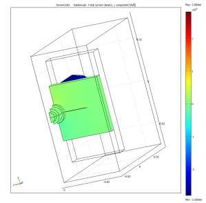
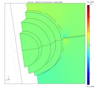
 t = 1.1 x 10⁻⁴ s t = 1.")
11 Reflection-Type Probe with Ferrous Fastener and Crack (Current Density Variation) t = 1.1 x 10⁻⁴ s t = 1.0 x 10⁻³ s ferrite = 2300, fastener = 66 11
12 12

13 Central Driver Differential Pickup (CDDP) Probe 3 Magnetic Flux Lines Ferrite Core Central Driver Differential Pickup Probe for Ferrous Fasteners Absolute Pickup Coil (10 mm from center ferrite core) 6 mm Ferrite Core Pickup Coils Driving Coil 38 mm Probe holder diameter 4 mm Pickup coil diameter Ferrous Fastener 2024 T3 Aluminum 12 mm Primary Coil Diameter Pickups 90 o Coupled (10mm from Ferrite core) Pickups 180 o Coupled (10 mm from ferrite core) 3 P. P. Whalen, Transient Eddy Current for the Detection Cracks in the vicinity of Ferrous Fasteners, M.Sc. Thesis, Royal Military College of Canada,
14 CDDP Probe Model Air Box Primary Circuit Secondary Circuit Ferrite Core R PC R SC R IN = 53 Driver R PV L P L S R SL 51 V meas Conducting Plates Ferrite core Pickup coil V meas Ferrous Fastener Notch 14
15 Pickup coil current (A) Differential pickup coil current (ma) CDDP Probe Model Results y = 8 mm (NS) y = 8 mm y = 10 mm (NS) y = 10 mm y = 12 mm (NS) y = 12 mm y = 14 mm (NS) y = 14 mm Probe Configuration Notch Depth = 1.6 mm Notch position: y = 2.4 to 11.9 mm Time(s) mm 10 mm 12 mm 14 mm 180 Probe Configuration Notch Depth = 1.6 mm Notch position: y = 2.4 to 11.9 mm Time (ms) 15
16 Differential pickup coil current (A) Pickup coil current (A) CDDP Probe Model Results contd mm 9 mm 10 mm 12 mm 14 mm mm 9 mm 10 mm 12 mm 14 mm Probe Configuration Notch Depth = 2.8 mm Notch position: y = 2.4 to 11.9 mm Time(s) 180 Probe Configuration Notch Depth = 3.6 mm Notch position: y = 2.4 to 11.9 mm Time(s) 16
17 Differential pickup coil current (ma) Differential pickup coil current (ma) CDDP Probe Model Results contd mm (real) 2.8 mm (real) 3.6 mm (real) mm (absolute) 2.8 mm (absolute) 3.6 mm (absolute) Probe Configuration Notch Depths: 1.6, 2.8 and 3.6 mm Notch position: y = 2.4 to 11.9 mm Probe Configuration Notch Depths: 1.6, 2.8 and 3.6 mm Notch position: y = 2.4 to 11.9 mm Position from center (mm) Position from center (mm) 17
18 Summary Commercial FE Modeling software has proved very successful in modelling the pulsed eddy current response in conducting plates having a notch in the presence of ferrous fastener. The models have been validated against experimental results. FE Modeling helped in investigating the effect of changing probe parameters on the probe characteristics. It also provided useful information on the diffusion of current density with time in conducting plates. Differential pickup signal from the CDDP probe is the strongest when the pickup coil lies close to the driver. The region near the tip of the notch is the transition region where the pickup signal may undergo an abrupt change in magnitude and/or polarity, which is also affected by the depth of the notch. The signal decreases with increase in notch depth. FE modeling appears to be very promising for studying multilayered airplane wing structures having cracks near the ferrous fasteners. It will potentially contribute in understanding and improving the methodology, design of new probes, and deal with a variety of complex physical situations. 18
19 Future Work Modelling notches of various sizes and at greater depths. New probes may be required to detect cracks that are smaller than the current diameter of the driver. New models to investigate the response of a 90 coupled CDDP probe. Additional work to study the variation in pickup signal by changing the magnetization level of the ferrous fastener. Model a replica of CDDP probe to include all the pickup coils in one model to take care of mutual inductances amongst various coils. 19
20 References & Useful Links 1. Pulsed Eddy Current Probe Design Based on Transient Circuit Analysis, T. J. Cadeau and T.W. Krause, Review of Quantitative Nondestructive Evaluation, Vol. 28, edited by D. O. Thompson and D. E. Chimenti, 2009, pp Finite Element Modeling of Pulsed Eddy Current Signals from Conducting Cylinders and Plates, V. K. Babbar, P. V. Kooten, T. J. Cadeau, and T. W. Krause, Review of Quantitative Nondestructive Evaluation, Vol. 28, edited by D. O. Thompson and D. E. Chimenti, 2009, pp Finite Element Modelling of Pulsed Eddy Current in Conducting Cylinders, T. W. Krause, V. Babbar and P. Van Kooten, Final Report Submitted to Aerospace Research Advisory Committee, Project# PH080401, Finite Element Modeling of Pulsed Eddy Current Signals from Aluminum Plates having Defects, V. K. Babbar, D. Harlley, and T. W. Krause, Review of Progress in Quantitative Nondestructive Evaluation, 29A, edited by D. O. Thompson and D. E. Chimenti, 2010, pp Increased field depth penetration with pulsed eddy current, T.J. Cadeau, M.Sc. Thesis, Royal Military College of Canada, Transient Eddy Current for the Detection Cracks in the vicinity of Ferrous Fasteners, P. P. Whalen, M.Sc. Thesis, Royal Military College of Canada, COMSOL Inc., Burlington, MA
21 Acknowledgements Aerospace Research Advisory Committee Academic Research Program at Royal Military College of Canada Natural Sciences and Engineering Research Council of Canada 21
22 Presenter Dr. V. K. Babbar Research Associate Department of Physics Royal Military College of Canada Questions? 22
23 Presenter Dr. V. K. Babbar Research Associate Department of Physics Royal Military College of Canada Thank You! 23