NON-CONVENTIONAL MACHINING METHODS
|
|
|
- Vernon Moody
- 5 years ago
- Views:
Transcription
1 NON-CONVENTIONAL MACHINING METHODS CONTENTS ABSTRACT CHAPTER 1: Introduction CHAPTER 2: Functions CHAPTER 3: Components CHAPTER 4: How car Suspension works CHAPTER 5: Types CHAPTER 6: Conclusion References
2 ABSTRACT The rapid developments in the field of materials has given an impetus to the modern manufacturing technology to develop, modify and is cover newer technological processes with a view to achieve results that are far beyond the scope of the existing conventional or traditional manufacturing processes. With the developments in the field of materials it has become essential to develop cutting tool materials and processes which can safely and conveniently machine such new materials for sustained productivity, high accuracy and versatility at automation. Consequently, non traditional techniques of machining are providing effective solutions to the problems imposed by the increasing demand for high strength temperature resistant alloys, the requirement of parts with intricate and compacted shapes and materials so hard as to defy machining by conventional methods. The processes are non traditional or non-conventional in the sense that they don t employ a conventional or traditional tool for material removal, instead, they directly utilize some form of energy for metal machining. Advance non conventional machining methods are following:- I. Electro Chemical Machining II. Abrasive Jet Machining III. Electro Beam Machining IV. Electro Discharge Machining V. Laser Beam Machining
3 Chapter 1. INTRODUCTION The development of harder & difficult ton machine metals & alloys such as tungsten, tantalum, beryllium, hast alloy, nitralloy, wasp alloy, nimonics, carbide, stainless steels and many other high strength temperature resistant (HSTR) alloys. These materials find wide application in aerospace, nuclear engineering and other industries going to their high strength to weight ratio, hardness and heat resisting qualities. The rapid developments in the field of materials has given an impetus to the modern manufacturing technology to develop, modify and is cover newer technological processes with a view to achieve results that are far beyond the scope of the existing conventional or traditional manufacturing processes. With the developments in the field of materials it has become essential to develop cutting tool materials and processes which can safely and conveniently machine such new materials for sustained productivity, high accuracy and versatility at automation. Consequently, non traditional techniques of machining are providing effective solutions to the problems imposed by the increasing demand for high strength temperature resistant alloys, the requirement of parts with intricate and compacted shapes and materials so hard as to defy machining by conventional methods. The processes are non traditional or non-conventional in the sense that they don t employ a conventional or traditional tool for material removal, instead, they directly utilize some form of energy for metal machining. Conventional machining methods always produce some stress in the metal being cut. Newer methods have been developed that are essentially stress free. Very thin metals can be cut without distortion or stress. The industries always face problems in manufacturing of components because of several reasons. This may be because of the complexity of the job profile or may be due to surface requirements with higher accuracy and surface finish or due to the strength of the materials. This challenge has been accepted and may new materials and unconventional methods of machining have been developed to suit the requirements of industry. The word unconventional means that the metals are such that they cannot be machined by conventional methods, but require some special techniques.
4
.")
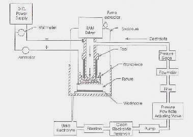
5 I. ELECTRO CHEMICAL MACHINING Electrochemical machining (ECM) is based on a controlled anodic electrochemical dissolution process of the workpiece (anode) with the tool (cathode) in an electrolytic cell, during an electrolysis process (Figure 1.1). Electrolysis is the name given to the chemical process which occurs, for example, when an electric current is passed between two electrodes dipped into a liquid solution. A typical example is that of two copper wires connected to a source of direct current and immersed in a solution of copper sulfate in water as shown in Figure Figure 1.2. Electrochemical cell [1] An ammeter, placed in the circuit, will register the flow of current. From this indication, the electric circuit can be determined to be complete. It is clear that copper sulfate solution obviously has the property that it can conduct electricity. Such a solution is termed as electrolyte. The wires are called electrodes, the one with positive polarity being the anode and the one with negative polarity the cathode. The system of electrodes and electrolyte is referred to as the electrolytic
6 cell, while the chemical reactions which occur at the electrodes are called the anodic or cathodic reactions or processes. A typical application of electrolysis is the electroplating and electroforming processes in which metal coatings are deposited upon the surface of a cathode-workpiece. Current densities used are in the order of 10-2 to 10-1 A/cm 2 and thickness of the coatings is sometimes more than 1 mm. An example of an anodic dissolution operation is electropolishing. Here the workpiece, which is to be polished, is made the anode in an electrolytic cell. Irregularities on its surface are dissolved preferentially so that, on their removal, the surface becomes smooth and polished. A typical current density in this operation would be 10-1 A/cm 2, and polishing is usually achieved on the removal of irregularities as small as 10 nm. With both electroplating and electropolishing, the electrolyte is either in motion at low velocities or unstirred. A number of what we call compound methods have been developed in which ECM is ganged up with some other form of metal-working, for example, mechanical (as in abrasive ECM), erosion (electric discharge-electrochemical machining), ultrasonic, etc. Among other things, diamond EC grinding makes it possible to handle cemented-carbide plates, blade flanges and locks, outer and inner surfaces of parts made of magnetic alloys, and to grind cutting tools. A typical Electrochemical machining system (Figure 1.11.) has four major subsystems: The machine itself The power supply The electrolyte circulation system The control system
7
8 Typical values of parameters and conditions of ECM are Power Supply presented Type: Voltage: Current: Direct Current 5 to 30 V (continue or pulse) 50 to 40,000 A Current Density: 10 to 500 A/cm 2 [ 65 to 3200 A/in 2 ]
9 Electrolyte Type and Concentration Most used: NaCl at 60 to 240 g/l [½ to 2 lb/gal] Frequently used: NaNO 3 at 120 to 480 g/l [1 to 4 lb/gal ] Less Frequently used: Proprietary Mixture Temperature : 20 to 50 o C [68 to 122 o F] Flow rate: Velocity : Inlet Pressure: 1 l/min/100a [0.264 gal/min/100a] 1500 to 3000 m/min [5000 to 10,000 fpm] 0.15 to 3 MPa [22 to 436 psi] Outlet Pressure: 0.1 to 0.3 MPa [15 to 43.6 Frontal Working Gap : Feed rate: Electrode material: Tolerance 0.05 to 0.3mm [0.002 to in] 0.1 to 20mm/min [0.004 to 0.7 in/min Brass,copper,bronze 2-dimensional shapes: 3-dimensioanl shapes: mm [ in] 0.1mm [0.004 in] Surface Roughness (Ra) 0.1 to 2.5 μm [4 to 100 microinches]
10 II. ABRASIVE JET MACHINING (AJM) The physics, Fine particles (0.025mm) are accelerated in a gas stream (commonly air at a few times atmospheric pressure) The particles are directed towards the focus of machining (less than 1mm from the tip) As the particles impact the surface, they fracture off other particles.
11 As the particle impacts the surface, it causes a small fracture, and the gas stream carries both the abrasive particles and the fractured (wear) particles away. Brittle and fragile work pieces work better. The factors are in turn effected by, 1. - the abrasive: composition; strength; size; mass flow rate 2. - the gas composition, pressure and velocity 3. - the nozzle: geometry; material; distance to work; inclination to work The abrasive, 1. - materials: aluminum oxide (preferred); silicon carbide 2. - the grains should have sharp edges 3. - material diameters of micro m is optimal 4. - should not be reused as the sharp edges are worn down and smaller particles can clog nozzle. Gas jet, 1. - mass flow rate of abrasive is proportional to gas pressure and gas flow 2.
12 1. - pressure is typically 0.2 N/mm2 to 1N/mm gas composition effects pressure flow relationship Nozzle 1. - must be hard material to reduce wear by abrasives: WC (lasts 12 to 30 hr); sapphire (lasts 300 hr) 2. - cross sectional area of orifice is mm orifice can be round or rectangular 4. - head can be straight, or at a right angle The relationship between head, and nozzle tip distance.
13 Summary of AJM characteristics 1. - Mechanics of material removal - brittle fracture by impinging abrasive grains at high speed 2. - media - Air, CO abrasives: Al2O3, SiC, 0.025mm diameter, 2-20g/min, non-recirculating 4. - velocity = m/sec 5. - pressure = 2 to 10 atm nozzle - WC, sapphire, orifice area mm2, life hr., nozzle tip distance mm 7. - critical parameters - abrasive flow rate and velocity, nozzle tip distance from work surface, abrasive grain size and jet inclination 8. - materials application - hard and brittle metals, alloys, and nonmetallic materials (e.g., germanium, silicon, glass, ceramics, and mica) Specially suitable for thin sections 9. - shape (job) application - drilling, cutting, deburring, etching, cleaning limitations - low metal removal rate (40 mg/min, 15 mm3/min), embedding of abrasive in workpiece, tapering of drilled holes, possibility of stray abrasive action.
14 III. ELECTRON BEAM MACHINING The basic physics is an electron beam is directed towards a work piece, the electron heat and vaporizes the metal. Typical applications are, 1. - annealing 2. - welding 3. - metal removal Electrons accelerated with voltages of approx. 150,000V to create velocities over 200,000 km/sec. Beam can be focused to 10 to 200 micro m and a density of 6500 GW/mm2 Good for narrow holes and slots. 1. e.g. a hole in a sheet 1.25 mm thick up to 125 micro m diameter can be cut almost instantly with a taper of 2 to 4 degrees The electron beam is aimed using magnets to deflect the stream of electrons A vacuum is used to minimize electron collision with air molecules. Beam is focused using an electromagnetic lens.
15 Summary of EBM Characteristics 1. - Mechanics of material removal - melting, vaporization 2. - Medium - vacuum 3. - Tool - beam of electrons moving at very high velocity 4. - Maximum mrr = 10 mm3/min 5. - Specific power consumption = 450W/mm3/min 6. - Critical parameters - accelerating voltage, beam current, beam diameter, work speed, melting temperature 7. - Materials application - all materials 8. - Shape application - drilling fine holes, cutting contours in sheets, cutting narrow slots 9. - Limitations - very high specific energy consumption, necessity of vacuum, expensive machine.
16 ULTRA SONIC MACHINING
17
18
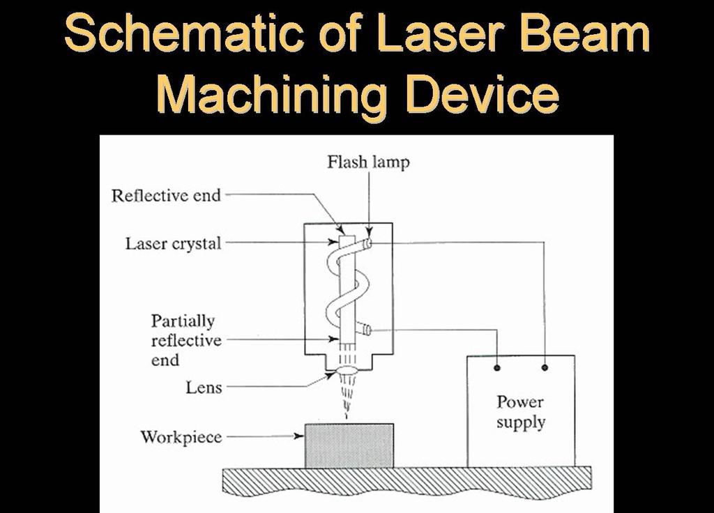
19 Laser Concept Add energy to make electrons jump to higher energy orbit Electron relaxes and moves to equilibrium at ground-state energy level Emits a photon in this process (key laser component) Two mirrors reflect the photons back and forth and excite more electrons One mirror is partially reflective to allow some light to pass through: creates narrow laser beam
20
21 Photon Emission Model Excited State Electron Ground State Photon Nucleus Orbits Electron is energized to the excited state Electron relaxes to ground state and photon is produced Applications in Industry Manufacturing of metal sheets for truck bed hitch plates Splicing of aluminum sheets in the aircraft industry Cutting of Multi Layered Insulation for spacecraft

22 More precise Useful with a variety of materials: metals, composites, plastics, and ceramics Smooth, clean cuts Faster process Decreased heat-affected zone Conclusions Brings science fiction to life Enforces the concept of lasers in cutting various materials More smooth, precise, and clean cuts can be created Applications are abundant in a variety of fields
23 ELECTRO DISCHARGE MACHINING Electro-discharge machining (EDM) is a widely used method for shaping conductive materials. EDM removes material by creating controlled sparks between a shaped electrode and an electrically conductive work piece. As part of the material is eroded, the electrode is slowly lowered into the work piece, until the resulting cavity has the inverse shape of the electrode. Dielectric fluid is flushed into the gap between the electrode andwork piece to remove small particles created by the process and to avoid excessive oxidation of the part surface and the electrode. The applications of EDM lie mainly in the tooling industry where it is applied on materials which are too hard to be machined with conventional techniques, such as milling or turning. The parts for these applications are usually larger than 1 mm, therefore conventional methods can be applied for fabricating the electrodes. Due to the fact that EDM can achieve very fine surface finishes, it has been trialed in the micromachining of conductive materials. For this purpose, copper electrodes obtained by LIGA (Lithographie Galvanoformung Abformung) have been used as die-sinking electrodes [1]. A related technique, wire electrodischarge grinding (WEDG), is also capable of fabricating parts with feature sizes below 100 _m [2, 3]. We dedicate thiswork to one of the pioneers of modern powder metallurgy, Claus G Goetzel, on the occasion of his 85th birthday. A few alternative methods exist for creating fine patterns in engineering materials. Wire EDM moves a fine wire, which is used as the electrode, through a sheet of part material and moves it along a programmed path. It can reach an excellent surface finish, however it is limited to parts with straight side walls. It cannot create blind holes, and requires highly accurate positioning equipment. Laser cutting (ablation) has been adapted for micromachining. Instead of electrical sparks, short laser pulses are used to selectively vaporize part material. This method does not require shaped electrodes, but, just like wire EDM, relies upon highly accurate actuators to move the laser over the part surface. The laser pulse rate is substantially lower than the spark pulse rate of micro-edm machines, which makes the process much slower. The aim of this work is to show that the application of silicon micromachining in combination with EDM can extend the range of feasible sizes of parts manufactured with shape deposition manufacturing (SDM) [4, 5] by at least one order of magnitude into the mesoscopic range (with part or feature size between 100 _m and 1 mm). For most applications of SDM silicon itself is not a suitable material due to its low fracture toughness and poor electrical and magnetic properties. In order to
24 be able to use engineering materials, silicon therefore serves as a mold for the following processing, in this case as mold for EDM electrodes.
25 Reference Journal 1. IEEE Journal IEEE Journal Internet 1. Convergent Prima. Laser Beam Machining. machining.html, 18 Oct Kalpakjian, Serope, and Steven R. Schmid. Manufacturing Engineering and Technology. Upper Saddle River, New Jersey: Prentice-Hall, Inc., Preco Laser Systems. Metal. (2002): 19 Oct Weschler, Matthew. How Lasers Work. How Stuff Works. (2002): 18 Oct Books 1. Dr. R.K. Jain 2. Dr. V.K. Jain 3. Dr. Ravi K. Goyal