Influence of reaction chamber shape on cast-iron spheroidization process in-mold
|
|
|
- Mariah Williams
- 5 years ago
- Views:
Transcription
1 A R C H I V E S of F O U N D R Y E N G I N E E R I N G Published quarterly as the organ of the Foundry Commission of the Polish Academy of Sciences ISSN ( ) Volume 10 Issue 1/ /1 Influence of reaction chamber shape on cast-iron spheroidization process in-mold S. Pietrowski Department of Materials Technologies and Production Systems, Technical University of Łódź, Stefanowskiego 1/15 Street, Łódź, Poland * Corresponding author. address: stanisław.pietrowski@p.lodz.pl Received ; accepted in revised form Abstract This paper presents a results concerning the influence of reaction chamber shape on cast iron spheroidization process in form. The volume of the tested reaction chambers was about mm 3. Reaction chambers in the shape of: rectangular, cylinder and spherical cap were examined. It has been shown that the best graphite spheroidizing process was provided by spherical cap chamber shape. The reaction of cast iron with magnesium in reaction chamber depends on the flow of cast iron in the chamber. In rectangular and cylinder shape chambers proceed the impact of diphase stream on flat bottom wall. It causes the creation on its surface film, called: cast iron film, where single grains of magnesium master alloy exist. The largest part of master alloy is drifted by liquid cast iron to the top and only there graphite spheroidization process proceed. In the spherical cap shape reaction chamber, as a result of rotation movement of liquid cast iron throughout its volume, graphite spheroidization process proceed. Apart from the reaction chamber shape, applying of mixing chamber ensure full cast iron spheroidization process. Keywords: Innovative foundry technologies and materials, Inmold, Reaction chamber, Microstructure 1. Introduction In the literature of item, informations concerning cast iron spheroidization process carried out by Inmold method are few. They concern the general description of technology, particularly its advantages [1 14]. In the paper [15], the possibility of cast iron spheroidization process by ATD method was presented. In the literature, particularly the necessity of control of every single cast made by Inmold method is underlined. This demonstrates the uncertainty of correctness of Inmold method, in terms of graphite spheroidization process. It consists of a number of factors related primarily to the construction of forms, namely: elements of gating system, reaction chamber and/or mixing chamber, number of casts as well as way of its disposal. The most important form element is reaction chamber where reaction of cast iron with magnesium proceed. Up to now, the influence of reaction chamber shape on graphite spheroidization process were not examined. Therefore, the aim of this study was to investigate the influence of reaction chamber shape on occurring cast iron spheroidization process. 2. Research methodology Cast iron was smelted in the laboratory induction crucible furnace with a capacity of 30kg and frequency of 15000Hz. Furnace charge consisted of Norway OB pig iron and St3 scrap steel. Cast iron spheroidization process in from were carried out by Inmold preliminary alloy, in quantities of 1,00% of cast iron bulk in form. Percentage chemical composition of cast iron was: 3,65% C; 2,81% Si; 0,49% Mn; 0,008% P; 0,005% S, 0,052% Mg. The influence of reaction chamber shape, at a constant mixing chamber, on cast iron spheroidization process were examined. Dimensions of the various shapes of reaction chamber were
2 selected as to possess similar volume about mm 3. Shapes and dimensions of the tested reaction chambers are presented in figure 1 (a c). a) Fig. 1. (a c). Shape and dimensions of reaction chamber: a rectangular; b cylinder; c spherical cap b) Shape and dimensions of mixing chamber are presented in figure 2. c) Fig. 2. Shape and dimensions of mixing chamber Metallographic studies were carried out on parts of reaction and mixing chambers sampling from surface layer and from the middle. 116
. According to fig.")
 from the bottom of chamber, grey cast iron exist with a large number of ferrite (c).")
 occurs mainly vermicular, compact and nodular graphite surrounded by ferrite in the ground of pearlite (d).")
.")

3 3. Results The change of graphite type and microstructure of cast iron metallic matrix at a height of rectangular reaction chamber with magnesium master alloy are showed in figure 3 (a f). According to fig.3, at the height of an average of 5mm (area 1) from the bottom of reaction chamber, grey cast iron exist with a small amount of ferrite (b). In a distance of about 7 9mm (area 2) from the bottom of chamber, grey cast iron exist with a large number of ferrite (c). Increasing the distance up to 18 20mm (area 3) causes occurrence of small amount of flake graphite. In this area (3) occurs mainly vermicular, compact and nodular graphite surrounded by ferrite in the ground of pearlite (d). A further increase of height up to 22 26mm (area 4) causes occurrence of few releases of vermicular graphite also, but mainly compact and nodular graphite surrounded by ferrite in the ground of pearlite (e). In the 5 th area compact and nodular graphite occurs surrounded by ferrite in pearlitic matrix (f). a) b) c) d) e) f) Fig. 3 (a f). The change of graphite type and microstructure of cast iron metallic matrix at a height of rectangular reaction chamber with magnesium master alloy: a scheme of reaction chamber; 1 5 microstructure investigations areas of cast iron in the average distance from the bottom of chamber, 1 b; 2 c; 3 d; 4 e; 5 f Related changes of cast iron microstructure exist at a height of cylinder reaction chamber as it is presented in figure 4 (a f). 117


 characteristic for layer 4 of rectangular and cylinder chambers is present (fig.")


4 a) b) c) d) e) f) Fig. 4. (a f). Changes of cast iron microstructure at a height of cylinder reaction chamber with magnesium master alloy; a reaction chamber scheme; 1 5 areas of cast iron microstructure investigations in the average distance from the bottom of chamber; 1 b; 2 c; 3 d; 4 e; 5 f However, there was a decrease of highness where specified microstructure exist in compare with rectangular chamber. In a different manner, from mentioned above, changes of cast iron microstructure in spherical cap shape reaction chamber proceed. It is shown in figure 5 (a e). According to fig.5 results that no grey cast iron layer exist there (1 and 2 fig.3 and 4). In the spherical cap within the limits of layer 1 vermicular, compact and nodular graphite (b) characteristic for layer 4 of rectangular and cylinder chambers is present (fig.3 and 4e). Over the 2 nd layer mainly compact and nodular graphite exist with small amount of vermicular graphite which similar as in layer 1 are surrounded by ferrite in ground of pearlite (c). Such microstructure remains also in layers 3 (d) and 4 (e). Scheme of cast iron microstructure changes in rectangular, cylinder and spherical cap shape chambers are presented in figure 6 and 7 respectively. Discussed of cast iron microstructure changes in reaction chambers with its various shape are caused by different two-phase stream flow in chamber. It is supposed to be that during fulfilling process of reaction chamber by liquid cast iron creates from the dissolve moment of magnesium master alloy two-phase stream. It results from fact that density of master alloy included between FeMgSi = 4,0 5,0G/cm 3 and its melting point is t topfesimg = C while an average density of nodular cast iron is Zsf = 7,25G/cm 3 and cast temperature t O = C. 118

 Fig. 6.")


5 a) b) c)) d) Fig. 5 (a e). Changes of cast iron microstructure at a height of spherical cap shape reaction chamber with magnesium master alloy; a reaction chamber scheme; 1 4 areas of cast iron microstructure investigations in the average distance from the bottom of chamber; 1 b; 2 c; 3 d; 4 e; 5 f. e) Fig. 6. Cast iron microstructure changes in rectangular and cylinder reaction chambers G graphite; G pł, G w, G z, G k respectively: flake, vermicular, compact and nodular Fig. 7. Cast iron microstructure changes in spherical cap reaction chambers G graphite; G pł, G w, G z, G k respectively: vermicular, compact and nodular Carried out modelling scientific researches with use of water and granules of high-molecular plastic revealed that in case of rectangular and cylinder shapes of reaction chambers follows an impact of two-phases stream into flat bottom wall of chamber. Scheme of it is shown in figure
6 Fig. 8. Layer scheme creation of two-phase stream in rectangular and cylinder shape reaction chamber Then at a certain height from the chamber bottom (flat wall) exist, so-called, in two-phases flows - liquid film. In the case of cast iron it can be called film of cast iron in which occurring and then are solving not numerous grains of master alloy (layer 1, fig. 3b). Thickness does not exceed of 5mm. Therefore, microstructure of cast iron over this area is consist of flake graphite, pearlite and about 5,0% of ferrite (microstructure of basic cast iron predicted for spheroidization process). Under the film the amount of master alloy grains increases, but not much enough so that relatively small amount of magnesium in master alloy could cause change of graphite shape. Due to the fact that in the preliminary alloy is large number of silicon which dissolves in cast iron in mentioned film so it causes creating of ferritic microstructure with small amount of pearlite (layer 2, fig. 3c). The thickness of this layer is between 1 4mm (b). The largest part of master alloy is floated by liquid cast iron to the top and over the layer 2 (b). Following its gradual dissolution and in the layer 3 (b) occur vermicular, compact and nodular graphite with the minimum quantity of flake graphite (fig. 3d). In the upper layer of reaction chamber occurs only compact and nodular graphite (fig. 3f). Depending on: the volume of reaction chamber, cast temperature and the speed of pouring of cast iron, some part of magnesium master alloy can not be dissolved in chamber but in the cross-gate or mixing chamber. In the spherical cap shape reaction chamber, two-phases flow proceed in other way from the previously described. Scheme of it is shown in figure 9. According to that in spherical cap shape chamber do not exist any film layer of liquid cast iron. During pouring in to the reaction chamber the cast iron proceed to very intensive rotational motion which entrainment master alloy grains occurring uniformly in a volume of liquid cast iron. Therefore throughout the volume of spherical cap vermicular, compact and nodular graphite exist, surrounded by ferrite in pearlitic matrix (fig. 5 a e). From the presented data results that the reaction between cast iron and magnesium in the reaction chamber do not proceed till to the end. Incomplete of reaction occurs primarily in rectangular and cylinder shape reaction chambers. Therefore, it is necessary to prolong the path of cast iron or appliance of mixing chamber with reaction chamber. Prolong the distance of cast iron by increase of cross-gate length does not always bring the desired result. The experimental studies have shown that in the cross-gate, in its bottom part exist flake graphite and in upper part nodular graphite, as a consequence it leads to diversification of graphite shape in cast. Therefore, it is necessary to match its relevant dimensions. From the analysis of influence of reaction chamber shape results that the best section of runner is semicircular crosssection. In the case of spherical cap shape reaction chamber, the increase of cast iron distance after reaction with magnesium, with use of semicircular cross-section cross-gate, ensure obtain of nodular graphite in casts. The best solution is to apply just next to the reaction chamber the mixing chamber where reaction between cast iron and magnesium will be completed, its mixing and uplifting of slag to the top of chamber surface will occurred. An example of affect of mixing chamber on graphite shape is shown in figure 10 (a f). According to above figure results that in mix chamber correct nodular graphite is obtaining which is present also in casts. Fig. 9. Scheme of two-phases stream in spherical cap shape reaction chamber 120
.")


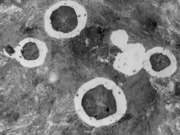
7 a) b) c) d) e) e) Fig. 10 (a f). Influence of mix chamber on graphites shape for: a cast iron microstructure in reaction chamber rectangular prism; c cast iron microstructure in reaction chamber cylinder; e cast iron microstructure in reaction chamber spherical cap; b, d, f cast iron microstructure in mix chamber 121
8 4. Conclusions From the presented at above work results it follows: the shape of reaction chamber effect in a significantly way on the reaction between liquid cast iron with magnesium; spherical cap shape of reaction chamber ensure the best graphite spheroidization; appliance of mixing chamber, by fulfil of other Inmold technology conditions, guarantees the nodular shape of graphite in casts. References [1] Sorelmetal Rio Tinto Iron & Titanium, [2] D.M. Stefanescu, R.C. Rao, J.W. Woolen, F.R. Juretzko, J.W. Torrance: Production of Thin-Wall Low-Nodurality Ductile Iron Trough the Delayed In-Mold Procesas. AFS Transactions, 2005, Vol. 110, s [3] R. Sillen: The PQ-CGI In-Mold Process, [4] Biuletyn Metals & Minerals, Technologie, 1/2001. [5] E. Guzik: Procesy uszlachetniania żeliwa. Wybrane zagadnienia. Archives of Foundry. Monografia Nr 1, [6] K.G. Davis i In.: Dissolution of MgFeSi alloy during inmold treatment, AFS Transactions, 1978, s [7] C.E. Dremann: New alloys for making ductile iron in the mold. AFS Transactions, 1983, s [8] Ductile Iron Molten Metal Processing, 2nd edition, American Foundrymen`s Society Publication, Des Plaines, IL, [9] H. Heine: Comparing seven methods for producing ductile iron, Foundry Management & Technology, August, [10] R. Steel: The use of the Flotret process for the production of large castings. BCIRA Conference S.G. Iron The Next 40 Years, Warwick, UK, [11] T. Bex: Ductile iron: one of the century`s metallurgical triumphs. Modern Casting, February, [12] J. Rotella, R. Mickelson: Using cored wire in the production of ductile iron, AFS Transactions, [13] S. Pietrowski, C. Rapiejko: Nodular cast iron and casting monitoring. Archives of Foundry Engineering, Vol. 8, Issue 3, July-September 2008, s [14] Projekt Celowy Nr ROW-II-363/2008 Kierownik Projektu: prof. dr hab. inż. Stanisław Pietrowski, [15] S. Pietrowski: Control of cast iron and casts manufacturing by Inmold method. Archives of Foundry Engineering, Vol. 8, Issue 3, July-September 2009, s