Enhanced Inspection Capability for Specific Applications using phased array ultrasonics
|
|
|
- Shanon Parrish
- 5 years ago
- Views:
Transcription
1 Malaysia NDT Conference November 2015 Enhanced Inspection Capability for Specific Applications using phased array ultrasonics Fredrik Hagglund Channa Nageswaran Lu Zhao John Rudlin
2 Content Plastic Pipe Weld Inspection Weld Overlay cladding Fatigue Crack monitoring Aluminothermic rail weld inspection


3 NDT of Plastic Pipe Joints Plastics are increasingly being used in nuclear and utility sectors >50% of gas distribution pipes in the US are made out of plastic Failures can occur Improper welding procedure Poor workmanship Contamination Need for an NDT system


4 Flaws in PE pipe joints Joint misalignment Axial/angular Poor pipe preparation Uneven planing Poor/no scraping Discrete planar flaws Fingerprints Oil/grease Rain droplets Particulates Airborne dust Dirt/sand Pipe under-penetration Cold fusions NDT of Plastic Pipe Joints


5 NDT of Plastic Pipe Joints Phased Array Ultrasonic Testing of plastic PE joints TWI s PolyTest system Full volumetric inspection EF and BF joints Thicknesses 8-65mm OD mm Manufacturing or in-service Locating/ sizing/ characterising defects Validated through mechanical testing


 20 days in the UK (130")
 10 days in")
 Good correlation with")
6 NDT of Plastic Pipe Joints Completed inspections for different industries across the world 30 days in South East Asia (270 joints in a 4km water pipeline) 20 days in the UK (130 joints in fabricated pipework for water transportation) 10 days in Italy (50 joints for gas pipelines) Good correlation with sectioned samples and mechanical tests
7 Clad systems of interest: Nickel Alloy 625 on X65 pipe Stainless steel 316L on vessel steel Inspection methods of interest: PAUT EMATs (ET and DPI) Flaw types of interest: Weld Overlay Cladding and inspection issues Fabrication stop/start, dis-bonds, inclusions Service - stress corrosion cracking
8 Weld Overlay Cladding Scattering, bending attenuation and reflection from coarse grains makes UT inspection difficult Conventional UT inspection can be successful using conventional shear wave probes with low frequencies Compression wave probes can also show some improvements TRL probes also assist with reduction of scattered reflections. However sometimes these methods fail and further enhancement is needed
9 Improvements with PA Improved interpretation using commercial PA probes Multiple PA probes to add information Dual matrix array probes (Olympus) to improve focussing flexibility of TRL type probe Improving techniques by modelling the grain structure and wave propagation through it

10 A case study Intermediate inspection of root and the hot pass in a Duplex 2209 girth weld with a metallurgical 316 SS cladding Analysis of the microstructure indicated that conventional shear wave inspection was theoretically possible according to the simple model presented earlier and on the analysis of the key parameters: grain size vs. wavelength.


11 Results verified by sectioning: root flaws Through-wall sizing is possible. in some cases

12 Composite PAUT tool

13 1mm FBH, 1mm through-wall

14 Area with no known flaws (1)
15 TWI is active on three technology fronts Group 1 Group 2 Group 3 Signal-to-noise how to optimise for a particular cladding system Improve the confidence of the operator training Qualify statistically to establish PoD/PoR How to screen rapidly over large surface areas using automation during fabrication / installation In-service application on pipelines and vessels (NII) Model the cladding in order to help optimise the ultrasonic techniques Influence welding in order to get the cladding suitable for inspection
16 Current Projects TWI has been contracted by the Pipeline Research Council International (PRCI) to perform R&D in welding, fatigue failure and inspection of weld overlay cladding Two phases have been completed to date, third phase will start in summer of 2015 focused on systematic qualification of the composite PAUT tool. For further information please contact Max Toch Work on finite element modelling of wave propagation in austenitic weld structure and its validation is ongoing in a TWI Core Research Project expected to end in late 2015 with submission of a report which will be available to Members in early 2016 Work on SCC in SS weld overlay cladding is part of an ongoing TWI Core Research Project expected to end in late 2015 with submission of a report which will be available to Members in early 2016
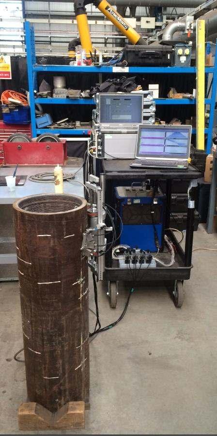
17 Fatigue Crack Monitoring Illustrates: Real time imaging of a growing crack Use of post-processed imaging methods (FMC/TFM) Measuring the size Engineering Critical Assessment Instrumentation: M2M GEKKO using real time FMC/TFM Olympus 10MHz 32 element linear array probe Component: Standard notched specimen in carbon steel Laboratory based fatigue testing machine
18 Designing ultrasonic techniques Array ultrasonic concepts required Focusing is essential to detect crack tip Steering for coping with changing geometry and manipulating incidence angles Electronic skewing using 2D arrays Information presented here make use of commercially available probes, instrumentation and software Ongoing developments are pushing boundaries of existing systems, leading to custom development of software in particular
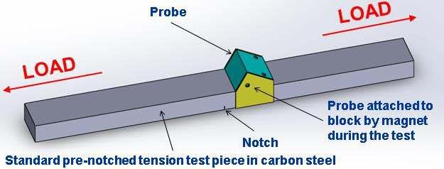
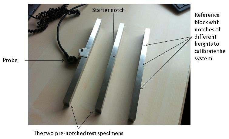
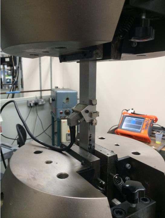
19 The setup
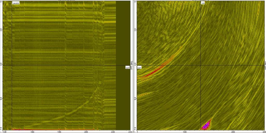
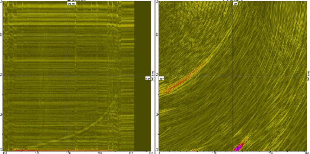
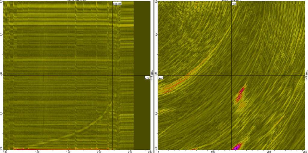
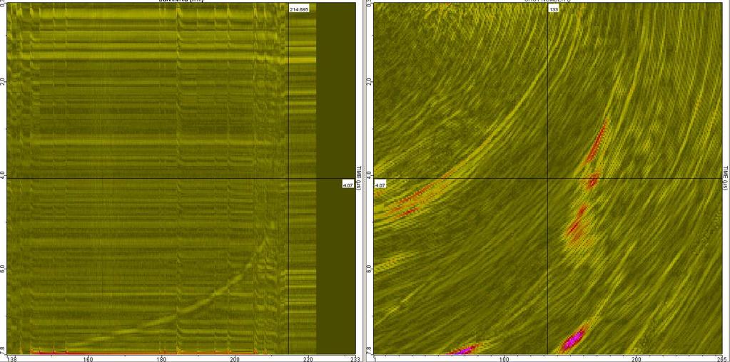
20 Processing the data in CIVA
21 da/dt towards Paris Law

22 Aluminothermic Welds in the Railway Industry The majority of field welding is carried out using aluminothermic welding. This casting method is : widely used for in-track welding during re-rail and defect replacement an effective, highly mobile and cost effective In the UK : 65,000 new welds per year produced by Network Rail and up to 2% rejection rate 1.5 million welds already on the main line railways In Europe: 300,000 to 400,000 new welds made per year 11 million welds estimated to be on track 20% of all rail failures estimated to be caused by weld failures


23 Welding Defects The most common volumetric defects for AT welding are: Porosity Lack of fusion Shrinkage These defects can cause welds to fail in months rather than years resulting in risk to safe operation and track closures for repairs


24 Phased array techniques Inspection Technique To steer, focus and scan beams with a single transducer assembly, 32:128 multiplex Focal laws were developed via modelling and trials Hardware consists of : 8 phased array probes Cables and connector box Computerised instrument for data acquisition and display Clamp on device, Railect system

25 Deployment of Railect System


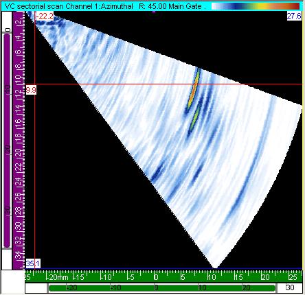


26 Inspection of the Ankle of the Rail Foot Transducer and focal laws parameters: 16 elements 5 MHz Sectorial scan Step 0.5 degree 3 mm notch 2 mm SDHs
27 Contacts Plastic Pipe Weld Inspection Weld Overlay and Fatigue Cracks- Alumino-thermic welds-