Merkel Sealing Technology for Injection-Molding Applications. Merkel Heavy Industry
|
|
|
- Verity Richard
- 5 years ago
- Views:
Transcription


1 Merkel Sealing Technology for Injection-Molding Applications Merkel Heavy Industry 1
2 2

3 Merkel Sealing Technology Seals and Sealing Systems for Injection-Molding Applications Installation recommendations for sealing systems plus descriptions with dimension tables of products used predominantly in injection molding applications Merkel Heavy Industry 3
4 4
5 List of contents Leading-edge seal competence in fluidics 4 Typical applications Sealing systems in injection-molding machines 8 Products Rod Seals Merkel U-ring T Merkel Omegat OMS-MR PR 33 Merkel Omegat OMSU-MR PR 41 Merkel Omegat OMS-S PR 44 Merkel Omegat OMS-S SR 49 Merkel Omegat OMS-DR HB 52 Piston Seals Merkel Omegat OMK-MR 57 Merkel Omegat OMK-DR HB 65 Wipers Merkel Double Wiper PT 1 71 Merkel Double Wiper PT 1-DR HB 66 Guides Merkel Guide Bush SBK 79 Merkel Guide Strip SF 90 Merkel Guide Bush KBK 99 Merkel Guide Strip KF 110 Rotary Seals Simmerring BAUMSL XL 121 Static Seals Merkel Pinmatic 127 Merkel Cover Seal PU Merkel Cover Seal PU Merkel Stircomatic SRC 142 Sectoral solutions 144 5

6 Merkel Seals and Sealing Systems for Injection-Molding Applications Merkel Heavy Industry: world-renowned sealing expertise Merkel Heavy Industry is the market leader in the field of seals for heavy industry. With innovative solutions and definitive products for all sectors, we rank among the world s best-thought-of experts on sealing technology. The quality of Merkel seals is recognized worldwide. For customized solutions to challenging problems, take advantage of our expertise in applications engineering, our profound expertise in material selection in conjunction with Freudenberg Research Services, and our sophisticated production technology. Their high functional reliability, coupled with excellent static and dynamic sealing effects, is regularly confirmed in comparative tests by all our customers at home and abroad, not least on a cross-sectoral basis. 6


7 Top-class sealing technology for absolutely clean production Merkel supplies compact-size sealing systems that ensure reliable sealing even under the extreme conditions encountered in the wide field of injection-molding machinery. The individual elements involved are optimally matched in terms of both materials and functionality, since all individual seals are developed as a system solution, and supplied from a single source. A long service life reduces costs Two-piece rod seal set with a very good sealing effect for linear and rotational movements. High wear-resistance and stable long term behavior make sure your maintenance and repair costs are minimized. Merkel seals in injection-molding machines Merkel Heavy Industry supplies you with high-performance seals for your entire production process. 7


8 Customized, field-proven, cost-efficient: the best sealing system for every requirement We provide sophisticated, top-quality sealing systems for sealing linear movements and radial sealing systems for applications such as: fast-stroke cylinders pressure pads closing cylinders moving cylinders injection cylinders sealing systems for stroke movement and combined redating-stroke movement. Development work is a crucial element in our globally successful product policy. For example, you will now find at Merkel a new product for toggle-joint machines: with the double-acting compact Merkel Pinmatic seal, you are guaranteed to secure yourself a loss-free, low-maintenance lubricant supply, thus significantly extending the service intervals involved. Merkel offers you firstly a high level of stock availability from conventional production methods, and secondly a fast-response capability for rush repair jobs, based on state-of-the-art lathe technology. 8


9 Merkel seals: Your competitive advantage Merkel Heavy Industry Due to their high extrusion resistance and their superior material quality, Merkel seals have no trouble standing up to high speeds and a wide range of temperatures. This means your machines can produce not only faster, but at significantly higher efficiencies into the bargain. The superior sealing effect can be relied upon to prevent leaks and resultant machine failures, thus saving you costly downtimes. At the same time, both service and repair outlays are reduced. Merkel Heavy Industry is part of Merkel Freudenberg Fluidtechnic GmbH in Hamburg, Germany. Around 900 employees develop, produce and sell seals and sealing systems for industrial applications. Merkel Freudenberg Fluidtechnic GmbH belongs to the Freudenberg Seals and Vibration Control Technology business unit, forms part of the globally operating Freudenberg Group, and is thus integrated into one of the world s biggest global partnership and sales networks for sealing technology. 9


10 Sealing systems Typical applications Sealing Systems in injection-molding machines Merkel supplies compact sealing systems that ensure reliable sealing even under the extreme conditions encountered in the wide field of injection-molding machinery. The individual elements involved are optimally matched in terms of both materials and functionality, since all individual seals are developed as a system solution, and supplied from a single source. By selecting materials specifically matched to these requirements, a very high pressure resistance capability is achieved, assuring long, functional life. 10

11 Closing unit fast-stroke cylinder Due to the high running speed involved, a comparatively thick coating of hydraulic oil remains on the counter surface. At the same time, because of the stroke length, a relevant quantity of hydraulic medium is transported at every stroke. By using the OMS-MR PR, a continuous pressure build-up in the space between the primary and secondary seals is prevented. Typical operating parameters Movement linear Pressure 20 MPa Stroke 1000 mm Running speed 1 m/s Rod diameter 80 mm Piston diameter 120 mm 11
12 Sealing systems Closing unit pressure pad Because of the short stroke involved, only a small amount of lubricant gets as far as the sealing edge and the guide elements. A lubricating film is not created. Sealing is effected in quasi-static mode, which means that here a secondary seal can be omitted without any restriction on functionality. Operating reliability is assured by the additional sealing edge of the PT 1 double wiper. The PTFE GM 201 (PTFE-glass-MoS2 compound) seal material used here possesses favorable sliding characteristics and behaves neutrally in relation to the counter surface. The patented Guivex geometry of the guide strips improves the intake of lubricant. Only a small support length can be provided between the guide strips, due to the compact construction of most cylinders. This means a relatively large angular offset may be encountered. Large sealing gaps can be implemented by using the OMS-S SR primary seal. The stress increase possible in the edge area of the guide strip with a severe angular offset is avoided by virtue of the patented Guivex geometry. The operating pressure is held for several minutes. The solid support edge in the PTFE Profile ring of the OMS-S SR increases the torsional stability and thus achieves favorable extrusion and wear behavior. The seal exhibits stable long term characteristics. Typical operating parameters Movement linear Pressure 20 MPa Stroke 5 mm Running speed - Rod diameter 440/760 mm Piston diameter 800 mm 12
13 Closing unit closing cylinder The maximum operating pressure is encountered only in the end position with a short stroke and a simultaneously minimal running speed. In this operating state, there is an inadequate film of oil under the sealing edge. The PTFE GM 201 (PTFE-glass-MoS2 compound) seal material unites the low friction properties of PTFE (especially regarding limited lubrication) with neutral behavior in relation to the counterface. Due to the high running speed, a comparatively thick coating of hydraulic oil film remains on the counter surface, particularly in low or zero pressure operation. At the same time, because of the stroke length involved, an adequate quantity of hydraulic medium is transported at every stroke. When the OMS-MR PR is used, a continuous pressure build-up in the space between the primary and secondary seals is prevented. Typical operating parameters Movement linear Pressure 20 MPa Stroke 1000 mm Running speed 1 m/s Rod diameter 80 mm Piston diameter 120 mm Movement Pressure Stroke Typical operating parameters for closing cylinder Running speed Rod diameter linear 20 MPa in the end position over 20 mm stroke 800 mm 1 m/s pressureless or at low pressure 400 mm 13
14 Sealing systems Injection unit injection cylinder Because of the comparatively low pressure on the low-pressure side, no typical primary seal is required. The sealing system s operating reliability is enhanced by the additional sealing edge of the PT 1 double wiper. The running speed during injection differs significantly from that during melting (pull-back). Since the thickness of the lubricant film is influenced by the running speed and the pressure, the oil balance is especially affected by low pressures. The optimized OMSU-MR PR assures the requisite minimization of oil film retention while simultaneously improving the reflow back capability at low pressures. Movement Pressure (injection) Pressure (pull-back) Stroke Running speed (injection) Running speed (pull-back) Rod diameter Piston diameter Typical operating parameters linear 20 MPa/0,2 MPa 3 MPa/0-3 MPa 120 mm 0,4 m/s 0,04 m/s 70/105 mm 120 mm 14
15 Injection unit injection cylinder (redating-stroke) The seals are stressed both in a stroke movement and in a combined redating-stroke movement. The operating pressure during stroke movements is specified at 25 MPa. In the case of rotational and rotary linear movements, the pressure of 2 MPa is exerted for a maximum of 5 s. The carefully matched geometry of the primary seal meets both the requirements entailed by the stroke movement in terms of sealing effect and pressure withstand capability, and those of the redational movement in regard to unwanted relative movement between the PTFE Profile ring and the prestressing element. In the case of a combined redating-stroke movement, as opposed to a purely linear movement, additional friction energy is imported into the system in the form of heat. Movement Pressure (ring space) Pressure (piston base) Stroke Running speed Redation Rod diameter Piston diameter Typical operating parameters redating-stroke 2 MPa 2 MPa/ 25 MPa (stroke only) 300 mm 0,5 m/s 3 m/s 250 mm 300 mm 15

16 Sealing systems Injection unit drive end (redating-stroke) Rotary movements sealed up to 2 MPa over short periods of operating pressure in addition to a purely static sealing function up to a pressure of 25 MPa. The Omegat OMS-DR HB makes sure that relative motion will arise exclusively between the slip ring and the sliding surface, even in the event of rotary movements. An appropriate extrusion and wear behavior is also ensured both by the geometrical configuration of the PTFE profile ring and the PTFE compound PTFE C104 (i.e. TFM-PTFE carbon-fiber compound) used here. The BAUMSL X7 Simmerring conceived for pure rotary movements provides, in such an application, both a wiping edge and an additional sealing edge aimed at retaining the residual oil film. No pressure is applied to the Simmerring. Typical operating parameters Movement redation Pressure (redation) 2 MPa Pressure (static) 25 MPa Velocity (redation) 3 m/s tmax 5 s Further applications Pressure cylinders, ejector cylinders, moving cylinders, locking cylinders. In the case of these cylinders, the same sealing systems are used as for fast-stroking cylinders, since the boundary conditions involved are largely similar. 16
17 17


18 18

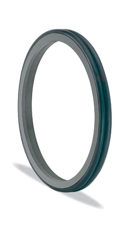
19 Rod seal Merkel Rod Seal U-Ring T 20 Polyurethane profile ring Asymmetrical sealing lip Material Material Designation Color Polyurethane 95 AU V142 dark blue Polyurethane 94 AU 925 light blue The material is determined by the nominal diameter and the production process involved. Applications Product description U-ring with asymmetrical profile for sealing piston rods. Product advantages extended service life in the sealing system, due to volume compensation functional reliability in the event of radial deflection due to profile size overlap operating reliability, due to sturdiness of the polyurethane profile ring high sealing effect, due to prominent sealing edge (high line force) secured against metallic contact by high extrusion resistance (large seal gap) favorable friction values at low pressures due to short contact length (secondary seal) simple and secure installation (single-piece element) Secondary seal in a sealing system Single seal in the pressure range up to 26 MPa Single seal for subordinate applications in the pressure range up to 40 MPa Nominal diameter up to 2,000 mm Field of application Material 95 AU V142/94 AU 925 Hydraulic oils, HL, HLP C HFA fluids C HFB fluids C HFC fluids C HFD fluids Water C HETG (rape-seed oil) C HEES (synth. ester) C HEPG (glycol) C Mineral greases C Pressure Running speed 40 MPa 0,5 m/s* * When the T 20 is used as a secondary seal, running speed of up to 1.5 m/s can be permitted. The figures given are maximum values and must not be applied simultaneously. 19
20 Rod seal Surface finish Peak-to-valley heights R a R max Sliding surface 0,05 0,3 µm <2,5 µm Groove base <1,6 µm <6,3 µm Groove sides <3,0 µm <15,0 µm Material content Mr > 50 % to max. 90 %, with cut depth c = Rz/2 and reference line Cref = 0 % The long term behavior of a sealing element and its dependability against early failures are crucially influenced by the quality of the counterface. Therefore a precise description and assessment of the surface is critical. Based on recent findings, we recommend supplementing the above definition of surface finish for the sliding surface by the characteristics detailed in the table below. With these new characteristics derived from the material content, the hitherto merely general description of the material content is significantly improved, not least in regard to the abrasiveness of the surface. See also Merkel Technical Manual. Surface finish of the sliding surfaces Characteristic value Ra > 0,05µm < 0,30µm Rmax Rpkx Rpk Limit < 2,5µm < 0,5µm < 0,5µm Rk >0,25µm <0,7µm Rvk >0,2µm <0,65µm Rvkx >0,2µm <2,0µm The limit values listed in the table do not currently apply for ceramic or semi-ceramic counterfaces. See also Merkel Technical Manual. Gap dimension The dimension D2 is determined by factoring in the maximum permissible extrusion gap, the tolerances, the guide clearance, the deflection of the guide under load, and the pipe expansion See also Merkel Technical Manual. The maximum permissible extrusion gap with a one-sided position of the piston rod is significantly determined by the maximum operating pressure and the temperature-dependent dimensional stability of the seal material. See also Merkel Technical Manual. Profile dimension Max. permissible gap dimension Profile 16 MPa 26 MPa 32 MPa 40 MPa 5,0 0,45 0,4 0,35 - > 5,0... 7,5 0,5 0,45 0,4 0,35 > 7, ,5 0,55 0,5 0,45 0,4 > 12, ,0 0,6 0,55 0,45 0,4 > 15, ,0 0,65 0,6 0,5 0,45 > 20, ,0 0,65 0,6 0,5 0,45 If the T 20 U-ring is used as a secondary seal in a sealing system, a larger gap dimension can be set. The general rule applying here is D2 = d + 1 mm with a tolerance of H11 for D2 400 or +0.4 for D2 >
21 Tolerances Diameter D Tolerance < 400 H11 > ,4 The tolerance for the diameters d and D2 is specified in connection with the gap dimension calculation. In typical hydraulic applications up to a nominal dimension of 1,000 mm, the tolerance fields f7 and f8 or H7 and H8 are usually chosen. Design notes For U-rings with a nominal dimension of d < 25 mm, an axially accessible housing is required. U-rings with a nominal dimension of d > 25 can generally be installed in a recessed groove using a fitting tool or by hand. Depending on the ratio of the nominal diameter to the Profile dimension, in individual cases an axially accessible housing will be required here as well (note in the article list). Housing recommendation for larger diameters (individual seal) d D L C > d > d > d Housing recommendation for larger diameters (secondary seal in a sealing system) d D L C > d > d > d Please note our general design remarks in the Merkel Technical Manual. Installation & assembly Reliable seal function is dependent on correct installation See also Merkel Technical Manual. 21

22 Rod seal Additional product description for U-ring T 20 In a sealing system, the space between the primary and secondary seals is filled with hydraulic medium after a few cycles. The further entry of media leads to an increase of the pressure in the intermediate space. If a U-ring is used as the secondary seal, then it will act as a volume compensator under pressure by reason of the moldrelease volume (Fig. 01). The pressure level in the intermediate space, and thus the thermal and mechanical loads as well, are effectively reduced. Merkel U-ring T 20 at 0 MPa Fig. 01 Merkel U-ring T 20 at 20 MPa Seal configuration The choice of a sealing element is crucially influenced by the material-dependent resistance to extrusion and the likewise material-dependent friction and wear behaviors. The values of the principal characteristics (sealing effect, dimensional stability and friction or wear) are mutually contradictory in this context. Depending on the operating and boundary conditions involved, U-rings made of Polyurethane are used as individual seals, but more frequently in an appropriate combination of individual sealing and guide elements as a secondary seal in a sealing system. The characteristics of the individual elements in a sealing system are optimized in line with the principal requirement involved. An individual seal, or the primary seal in the system concerned, is exposed to the operating pressure. The principal requirement being high resistance to extrusion coupled with favorable frictional values under high pressure. The secondary seal in a sealing system is exposed to the low intermediate space pressure. The principal requirements in this case are the effective reduction of the residual-oil film released via the primary seal, coupled with favorable frictional values at low pressures. Mold-release volume Sealing effect An element s sealing effect is described in terms of the ratio between the wiping effect and the return capability. The initial sealing effect of compact, two-piece sealing elements is achieved by pressing the prestressing element. There is thus, of course, a close interdependence between the deformation of the loading element and the force being applied. A small change in the compression (due to tolerances and radial movement) results in a relevant change in the force being applied and thus ultimately in the sealing effect. In the case of the T 20 U-ring, the initial sealing effect is entailed by the deformation of the sealing lips. Small changes in the radial contact pressure do not produce any relevant change in the pressure exerted by the sealing edge. The U-ring s geometry is thus, at a consistently high level of functionality, tolerant to radial deflections. In the high-pressure range, many sealing elements exhibit a satisfactory sealing effect, attributable solely to the high contact pressure on the counterface. In the pressure range up to 5 MPa (intermediate space pressure in the sealing system), by contrast, the sealing effect is crucially influenced by the edge geometry and the contact stress. The compression characteristic under the sealing edge is generally optimized so as to ensure effective wiping ability in the pressure chamber (rapid pressure rise) and a good return capability from the back (slow pressure rise). (See Fig. 02) 22
23 In comparison to compact sealing elements, the U-ring geometry of the T 20 exhibits a short contact length at low pressure, with a definite pressing maximum value. The oil film is effectively downsized here, all that remains is the wetting on the counterface, desirable in terms of the sliding characteristics. Friction With sealing elements made of polyurethane, the material properties mean that a high sealing effect is achieved. Depending on the force being applied and the size of the contact area, the seal material is intermeshed to a greater or lesser extent with the counterface. The closer the contact, the higher the friction force will be. Due to the small contact length of a PU U-ring in the low-pressure range, significantly lower friction values are achieved in comparison to compact sealing elements made of polyurethane. As the secondary seal in a sealing system, the T 20 U-ring is subjected to significantly less than the mold-release pressure. If, however, the U-ring is being used as an individual seal, the operating pressure may rise to a level above the U-ring s mold-release pressure. Because of the increased intermeshing between the seal material and the counter surfacedue to the enlarged contact area, the amount of friction rises. If the working pressure is between 5 MPa and 10 MPa, the frictionoptimized version LF 300 (LF = low friction ) with a grooved contact surface is the preferable option. Extrusion The resistance to extrusion is essentially determined by the properties of the seal materials. In addition, not only the size of the deformation, but the deformation volume available also plays a crucial role. Due to the generally larger volume provided by a U-ring, larger gaps can be permitted here under otherwise identical boundary conditions in comparison to a compact seal with a slip ring made of Polyurethane. This significantly reduces the possibility of unwanted metallic contacts. The sealing system s service life is extended by using the T 20 U-ring in the sealing system concerned, since as a volume compensator it substantially reduces the thermal and mechanical stresses involved, thus assuring stable long term behavior. Due to a U-ring s larger deformation volume, larger gaps can be permitted, thus significantly reducing the possibility of metallic contacts. The T 20 U-ring exhibits an edge geometry designed for optimum sealing effect. Individual seals and sealing systems with a T 20 U-ring as the secondary seal score highly in terms of a very good sealing effect. Fig. 02: Contact stress p and contact height h for the T 20 U-ring, extending rod at 0.5 MPa operating pressure, 0.28 m/s velocity 23
24 Rod Seal rounded and burr-free R2 < 0,2 rounded and burr-free Housing d D H L Profile C Installation* Material Article No ,5 h 95 AU V , ,0 h 95 AU V ISO , ,5 h 95 AU V ,5 h 95 AU V ,0 w 95 AU V ,5 5,5 w 95 AU V ISO ,4 12,5 7,5 5,5 w 95 AU V , ,0 a 95 AU V , ,5 h 95 AU V ,5 h 95 AU V , ,5 h 95 AU V , ,5 h 95 AU V ,5 h 95 AU V , ,5 h 95 AU V ,7 9,6 6 5,0 w 95 AU V ,0 w 95 AU V ,5 5,5 w 95 AU V ,4 13 7,5 5,5 w 95 AU V ISO ,4 12,5 7,5 5,5 w 95 AU V ,5 h 95 AU V , ,5 h 95 AU V ,5 h 95 AU V , ,5 w 95 AU V Further dimensions on request * a = axially accessible housing; h = by hand; w = with fitting tool 24
25 Housing d D H L Profile C Installation* Material Article No ,0 h 95 AU V ,4 11 7,5 5,5 w 95 AU V ,4 12,5 7,5 5,5 w 95 AU V ,4 13 7,5 5,5 w 95 AU V ,6 18,2 10 6,0 a 95 AU V ISO ,4 12,5 7,5 5,5 w 95 AU V ISO , ,0 a 95 AU V , ,5 h 95 AU V , ,5 h 95 AU V , ,5 h 95 AU V ,7 9,6 6 5,0 h 95 AU V ,5 5,5 w 95 AU V ,4 13 7,5 5,5 w 95 AU V , ,0 a 95 AU V , ,5 h 95 AU V , ,5 h 95 AU V ,7 9,6 6 5,0 h 95 AU V ,5 5,5 w 95 AU V ISO ,4 12,5 7,5 5,5 w 95 AU V ,4 13 7,5 5,5 w 95 AU V ,5 8 5,5 w 95 AU V , ,0 w 95 AU V ISO , ,0 w 95 AU V ,5 5 4,5 h 95 AU V ,7 9,6 6 5,0 h 95 AU V ,5 5,0 h 95 AU V ,9 7,5 5,5 h 95 AU V ,5 5,5 w 95 AU V , ,0 w 95 AU V , ,5 h 95 AU V ,5 h 95 AU V , ,5 h 95 AU V ,7 9,6 6 5,0 h 95 AU V Further dimensions on request * a = axially accessible housing; h = by hand; w = with fitting tool 25
26 Rod Seal rounded and burr-free R2 < 0,2 rounded and burr-free Housing d D H L Profile C Installation* Material Article No ,9 7,5 5,5 h 95 AU V ,5 5,5 h 95 AU V ISO ,4 12,5 7,5 5,5 h 95 AU V ,4 13 7,5 5,5 h 95 AU V , ,0 w 95 AU V ISO , ,0 w 95 AU V ,8 12,5 5 4,5 h 95 AU V ,7 9,6 6 5,0 h 95 AU V ,9 7,5 5,5 h 95 AU V ,5 5,5 h 95 AU V ,4 12,5 7,5 5,5 h 95 AU V ,4 13 7,5 5,5 h 95 AU V ,7 6,3 4 4,5 h 95 AU V , ,5 h 95 AU V ISO ,8 7,5 5 4,5 h 95 AU V ,5 h 95 AU V ,7 9,6 6 5,0 h 95 AU V ,5 5,5 h 95 AU V ISO ,4 12,5 7,5 5,5 h 95 AU V ,4 13 7,5 5,5 h 95 AU V , ,0 w 95 AU V ISO , ,0 w 95 AU V ,9 7,5 5,5 h 95 AU V ,5 5,5 h 95 AU V Further dimensions on request * a = axially accessible housing; h = by hand; w = with fitting tool 26
27 Housing d D H L Profile C Installation* Material Article No ,8 13 7,5 5,5 h 95 AU V , ,0 w 95 AU V ,2 10 6,0 w 95 AU V ,9 7,5 5,5 h 95 AU V ,5 5,5 h 95 AU V ,9 12 7,5 5,5 h 95 AU V ,4 13 7,5 5,5 h 95 AU V , ,0 w 95 AU V ,2 10 6,0 w 95 AU V ISO , ,0 h 95 AU V ,5 h 95 AU V ,5 h 95 AU V ,4 12,5 7,5 5,5 h 95 AU V , ,0 h 95 AU V ,7 8,5 5 4,5 h 95 AU V ,9 7,5 5,5 h 95 AU V ISO ,6 10,6 7,5 5,5 h 95 AU V ,9 12 7,5 5,5 h 95 AU V ,5 5,5 h 95 AU V , ,0 h 95 AU V ISO , ,0 w 95 AU V ,9 12 7,5 5,5 h 95 AU V , ,0 w 95 AU V , ,5 6,5 w 95 AU V ,9 12 7,5 5,5 h 95 AU V , ,0 h 95 AU V , ,5 6,5 w 95 AU V ,9 12 7,5 5,5 h 95 AU V ISO , ,0 h 95 AU V , ,5 w 95 AU V ,5 h 95 AU V ,5 5,5 h 95 AU V ,7 15 7,5 5,5 h 95 AU V ,6 16 7,5 5,5 h 95 AU V , ,0 h 95 AU V , ,5 w 95 AU V , ,0 a 95 AU V , ,5 w 95 AU V Further dimensions on request * a = axially accessible housing; h = by hand; w = with fitting tool 27
28 Rod Seal rounded and burr-free R2 < 0,2 rounded and burr-free Housing d D H L Profile C Installation* Material Article No ,6 9,5 6 5,0 h 95 AU V , ,0 a 95 AU V ISO , ,0 h 95 AU V , ,5 w 95 AU V ,5 9,5 6 5,0 h 95 AU V , ,0 h 95 AU V , ,0 h 95 AU V , ,0 h 95 AU V , ,5 w 95 AU V , ,0 h 95 AU V ,6 16 7,5 5,5 h 95 AU V , ,0 h 95 AU V , ,0 h 95 AU V ISO , ,5 6,5 h 95 AU V , ,5 w 95 AU V ,6 16 7,5 5,5 h 95 AU V , ,0 h 95 AU V , ,0 h 95 AU V , ,0 h 95 AU V , ,0 h 95 AU V , ,0 h 95 AU V ISO , ,5 6,5 h 95 AU V , ,5 w 95 AU V ISO , ,5 w 95 AU V ,4 12,5 7,5 5,5 h 95 AU V , ,0 h 95 AU V Further dimensions on request * a = axially accessible housing; h = by hand; w = with fitting tool 28
29 Housing d D H L Profile C Installation* Material Article No , ,0 h 95 AU V ,1 18,8 12,5 6,5 h 95 AU V ,4 12,5 7,5 5,5 h 95 AU V , ,0 h 95 AU V ISO , ,5 6,5 h 95 AU V , ,5 w 95 AU V , ,0 h 95 AU V , ,0 h 95 AU V , ,0 h 95 AU V , ,5 6,5 h 95 AU V , ,5 h 95 AU V , ,0 h 95 AU V , ,5 h 95 AU V ISO , ,5 h 95 AU V , ,5 h 95 AU V , ,0 h 95 AU V , ,0 h 95 AU V , ,0 h 95 AU V , ,0 h 95 AU V , ,5 h 95 AU V ,8 15 7,5 h 95 AU V ,1 15,5 11 6,5 h 95 AU V , ,0 h 95 AU V , ,5 h 95 AU V , ,5 h 95 AU V , ,5 h 95 AU V , ,0 h 95 AU V , ,0 h 95 AU V , ,5 h 95 AU V , ,5 h 95 AU V , ,0 h 95 AU V , ,0 h 95 AU V , ,5 h 95 AU V , ,5 h 95 AU V , ,5 h 95 AU V ,5 10 6,0 h 95 AU V , ,5 h 95 AU V , ,5 h 95 AU V Further dimensions on request * a = axially accessible housing; h = by hand; w = with fitting tool 29
30 Rod Seal rounded and burr-free R2 < 0,2 rounded and burr-free Housing d D H L Profile C Installation* Material Article No , ,5 h 95 AU V , ,5 h 95 AU V ,5 23,6 15 7,5 h 95 AU V , ,5 h 95 AU V , h 95 AU V , h 95 AU V , h 95 AU V , h 95 AU V , h 95 AU V , h 95 AU V , h 95 AU V , h 95 AU V , h 95 AU V , h 95 AU V , h 95 AU V , h 95 AU V , h 95 AU V , h 95 AU V , h 95 AU V , h 95 AU V , h 95 AU V , h 95 AU V Further dimensions on request * a = axially accessible housing; h = by hand; w = with fitting tool 30
31 Housing d D H L Profile C Installation* Material Article No , h 95 AU V , h 95 AU V , h 95 AU V , h 95 AU V , h 95 AU V , h 95 AU V , h 95 AU V , h 95 AU V , h 95 AU V , h 95 AU V , h 95 AU V , h 95 AU V , h 95 AU V , h 95 AU V , h 95 AU V , h 95 AU V , h 95 AU V , h 94 AU , h 94 AU , h 94 AU , h 94 AU , h 94 AU , h 94 AU , ,5 10 h 94 AU , ,5 10 h 94 AU , ,5 10 h 94 AU , ,5 10 h 94 AU , ,5 10 h 94 AU , ,5 10 h 94 AU , ,5 10 h 94 AU , ,5 10 h 94 AU , ,5 10 h 94 AU , ,5 10 h 94 AU Further dimensions on request * a = axially accessible housing; h = by hand; w = with fitting tool 31
32 Rod Seal rounded and burr-free R2 < 0,2 rounded and burr-free Housing d D H L Profile C Installation* Material Article No , ,5 10 h 94 AU , ,5 10 h 94 AU , ,5 10 h 94 AU , ,5 10 h 94 AU , ,5 10 h 94 AU , ,5 10 h 94 AU , ,5 10 h 94 AU , h 94 AU , h 94 AU , h 94 AU Further dimensions on request * a = axially accessible housing; h = by hand; w = with fitting tool 32
33 Merkel Rod Seal OMS-MR PR O-ring Pressure relief bore PTFE Profile ring Product description Two-piece seal set for sealing piston rods, consisting of a PTFE Profile ring with an integrated pressure relief function, plus an O-ring as a prestressing element. Patented product design. (Patent No.: DE CI) Product advantages interchangeable with housings of the OMS-MR series enhanced operating reliability of sealing systems with tough operating parameters (no continuous pressure build-up in the intermediate space extended service life of sealing systems due to stable long term behavior (reduced loads on the sealing system from friction and wear) Applications Primary seal in a sealing system Long stroke (greater than 400 mm) High running speed when the piston rod is extended (greater than 0.5 m/s) Sizeable velocity differences in dependence on the direction of motion (v ext greater than 8x v retr ) Fast pressure drop in the main chamber Field of application Material PTFE GM201/NBR PTFE C104/NBR Hydraulic oils, HL, HLP C HFA fluids C HFB fluids C HFC fluids C HFD fluids - Water C HETG (rape-seed oil) C HEES (synth. ester) C HEPG (glycol) C Mineral greases C Pressure Running speed 40 MPa 5 m/s The figures given are maximum values and must not be applied simultaneously. Material PTFE profile ring Material Designation Color PTFE-glass-fiber-MoS2 compound PTFE GM201 light-gray PTFE-carbon-fiber compound PTFE C104 dark-gray O-ring Material Nitrile rubber Fluor caoutchouc Designation NBR FKM Other material combinations available on request. 33
34 Rod Seal Surface finish Peak-to-valley heights R a R max Material content Mr > 50 % to max. 90 %, with cut depth c = Rz/2 and reference line Cref = 0 % The long term behavior of a sealing element and its dependability against early failures are crucially influenced by the quality of the counterface. Therefore a precise description and assessment of the surface is critical. Based on recent findings, we recommend supplementing the above definition of surface finish for the sliding surface by the characteristics detailed in the table below. With these new characteristics derived from the material content, previous more general descriptions of the material content are significantly improved, especially in regard to surface roughness. See also Merkel Technical Manual. Surface finish of the sliding surfaces Characteristic value Limit Ra > 0,05µm < 0,30µm Rmax Rpkx Rpk Sliding surface 0,05 0,3 µm <2,5 µm Groove base <1,6 µm <6,3 µm Groove sides <3,0 µm <15,0 µm < 2,5µm < 0,5µm < 0,5µm Rk >0,25µm <0,7µm Rvk >0,2µm <0,65µm Rvkx >0,2µm <2,0µm The limit values listed in the table do not currently apply for ceramic or semi-ceramic counterfaces. See also Merkel Technical Manual. Gap dimension The dimension D2 is determined by factoring in the maximum permissible extrusion gap, the tolerances, the guide clearance and the deflection of the guide under load. The maximum permissible extrusion gap with a one-sided position of the piston rod is significantly determined by the maximum operating pressure and the temperature-dependent dimensional stability of the seal material. See also Merkel Technical Manual. Profile dimension Max. permissible gap dimension L Profile 16 MPa 26 MPa 32 MPa 40 MPa 4,2 5,35 0,5 0,4 0,3-6,3 7,55 0,55 0,45 0,35 0,3 8,1 10,25 0,6 0,5 0,4 0,4 8,1 12 0,7 0,6 0,55 0,5 At an operating temperature of above 90 C, and simultaneous exposure to an operating pressure of more than 26 MPa, we recommend the use of the material compound PTFE B602 and PTFE C104. Tolerances Diameter D Tolerance < 500 H8 > 500 H7 The tolerance for the diameter d and D2 is specified in connection with the gap dimension calculation. In typical hydraulic applications up to a nominal dimension of 1,000 mm, the tolerance fields f7 and f8 or H7 and H8 are usually chosen. Installation & assembly Reliable seal function is dependent on correct installation. See also Merkel Technical Manual. 34
35 Functional principle Ill. 2 The Omegat OMS-MR PR features an integrated pressure relief function. As soon as the pressure in the intermediate space pz becomes greater than the main-compartment pressure ph (caused, for example, by unfavorable velocity conditions during extension and retraction), the seal can be relied on to relieve the pressure. The sealing function of the Omegat OMS-MR PR corresponds to that of the field-proven Omegat seals. Pressure relief in non-operative state Pressure relief in function Intermediate space Main compartment Intermediate space Main compartment pz = pressure in the intermediate space; ph = pressure in main compartment 35

36 Rod Seal Additional product description for Omegat OMS-MR PR The temperature rises, and thus not only fosters deformation of the PTFE Profile ring of the primary seal under load, but also reduces the extrusion resistance of the secondary seal. Because of the increased friction, moreover, intensified wear can be expected, and due to the frictional heat produced, accelerated aging of the hydraulic medium can also be anticipated. Intermediate-space pressure In operation, the space between the primary and secondary seals is filled with hydraulic medium after a few cycles. The further entry of media leads to an increase of the pressure in the intermediate space. If a U-packing is used as the secondary seal, then it will act as a volume compensator under pressure by reason of the mold-release volume, thus contributing towards reducing the general pressure level. Normally, the pressure in the intermediate space will settle at up to 5 MPa, in dependence on the operating parameters, and is then reduced again with a temporal offset to the main compartment s pressure during the return stroke. Pressure build-up In the case of a large stroke length (> 400 mm), and a high running speed (> 0.5 m/s) while the rod is being extended, but also as a consequence of vibrations and in the case of major differences in velocity in dependence on the direction of motion (v retr greater than 8x v ext ), a comparatively larger volume of oil is released into the intermediate space under the sealing edge than comes out of it. If these or similar operating parameters apply, a significantly increased pressure level will be formed in the intermediate space. The higher pressure is reduced incompletely during the return stroke, and can be accumulated over a number of cycles. The pressure level can here rise continuously until it exceeds the operating pressure. The increased pressure in the intermediate space results in an increased amount of friction. If, as a result of the above-mentioned phenomena, the pressure in the intermediate space is significantly higher than in the main compartment, then the prestressing element of the primary seal (O-ring) will be pushed towards the main compartment. The PTFE Profile ring of the primary seal is thereby twisted over the neutral position towards the main compartment; this movement causes the sealing edge to become gradually more rounded, and the sealing function of the primary seal is disturbed. As this goes on, the profile ring may tilt completely to the main compartment, which will ultimately lead to extrusion of the primary and secondary seals, and thus to the system s failure. Leakage will only become visible outside the sealing system, when the secondary seal is no longer performing its function. Pressure relief Building successfully on the field-proven functionality of the Omegat series, the Omegat OMS-MR PR possesses a pressure-relief feature integrated into the Profile ring. As soon as the pressure in the intermediate space is greater than in the main compartment, the pressure-relief bore is opened, and can be relied on to relieve the pressure in the intermediate space down to the pressure in the main compartment. A lasting inclusion of overpressure in the intermediate space is not possible here. In operation, the pressure in the main compartment is higher than in the intermediate space. The pressure-relief bore is closed in contact between the PTFE Profile ring and the wall of the compartment (Fig. 01). If the pressure in the intermediate space rises to a level above that in the main compartment, then the contact between the PTFE Profile ring and the wall is broken (Fig. 02). Since the pressure is equalized directly via the pressure-relief bore, the prestressing element remains on the side facing the intermediate space. The Profile ring will not tilt towards the main compartment. 36
37 Pressure relief in non-operative state Pressure relief in function Intermediate space Main compartment Intermediate space Main compartment pz = pressure in the intermediate space; ph = pressure in main compartment Fig. 01 Fig. 02 With the patented pressure-relief feature, the pressure in the intermediate space is held independently of the operating conditions at a level favorable for continuous operation. By virtue of the low thermal and mechanical stress on the sealing elements, a stable long term behavior is achieved, and the sealing system s service life is extended. The functionality of the pressure-relief feature renders the sealing system tolerant to the external influences acting on it during operation. Operating reliability is thus enhanced across the board by using the Omegat OMS-MR PR. Using the Omegat OMS-MR PR makes an important contribution towards the reliability and long lifetimes of hydraulic cylinders. Using the Omegat OMS-MR PR will eliminate downtimes caused by intermediate-space pressure, thus substantially reducing your complaint-related costs and cutting the amount of maintenance required by up to 30 %. 37
38 Rod Seal rounded and burr-free R2 < 0,2 rounded and burr-free d D H L Profile C Material Article No ,1 5,9 6,3 7,55 5,5 PTFE C104/NBR ,1 5,9 6,3 7,55 5,5 PTFE GM201/NBR ,1 5,9 6,3 7,55 5,5 PTFE C104/NBR ,1 5,9 6,3 7,55 5,5 PTFE GM201/NBR ,1 5,9 6,3 7,55 5,5 PTFE GM201/NBR ,1 5,9 6,3 7,55 5,5 PTFE C104/NBR ,1 5,9 6,3 7,55 5,5 PTFE C104/NBR ,1 5,9 6,3 7,55 5,5 PTFE GM201/NBR ,1 5,9 6,3 7,55 5,5 PTFE C104/NBR ,1 5,9 6,3 7,55 5,5 PTFE GM201/NBR ,1 5,9 6,3 7,55 5,5 PTFE GM201/NBR ,1 5,9 6,3 7,55 5,5 PTFE C104/NBR ,1 5,9 6,3 7,55 5,5 PTFE GM201/NBR ,1 5,9 6,3 7,55 5,5 PTFE C104/NBR ,1 5,9 6,3 7,55 5,5 PTFE C104/NBR ,1 5,9 6,3 7,55 5,5 PTFE GM201/NBR ,1 5,9 6,3 7,55 5,5 PTFE C104/NBR ,1 5,9 6,3 7,55 5,5 PTFE GM201/NBR ,1 5,9 6,3 7,55 5,5 PTFE GM201/NBR ,1 5,9 6,3 7,55 5,5 PTFE C104/NBR ,1 5,9 6,3 7,55 5,5 PTFE GM201/NBR ,1 5,9 6,3 7,55 5,5 PTFE GM201/NBR ,1 5,9 6,3 7,55 5,5 PTFE C104/NBR ,1 5,9 6,3 7,55 5,5 PTFE GM201/NBR ,1 5,9 6,3 7,55 5,5 PTFE C104/NBR ,1 5,9 6,3 7,55 5,5 PTFE GM201/NBR Further dimensions on request 38
39 d D H L Profile C Material Article No ,1 5,9 6,3 7,55 5,5 PTFE C104/NBR ,1 5,9 6,3 7,55 5,5 PTFE GM201/NBR ,1 5,9 6,3 7,55 5,5 PTFE C104/NBR ,1 5,9 6,3 7,55 5,5 PTFE C104/NBR ,1 5,9 6,3 7,55 5,5 PTFE GM201/NBR ,1 5,9 6,3 7,55 5,5 PTFE C104/NBR ,1 5,9 6,3 7,55 5,5 PTFE C104/NBR ,1 5,9 6,3 7,55 5,5 PTFE GM201/NBR ,1 5,9 6,3 7,55 5,5 PTFE C104/NBR ,1 5,9 6,3 7,55 5,5 PTFE C104/NBR ,1 5,9 6,3 7,55 5,5 PTFE C104/NBR ,1 5,9 6,3 7,55 5,5 PTFE GM201/NBR ,1 5,9 6,3 7,55 5,5 PTFE C104/NBR ,1 5,9 6,3 7,55 5,5 PTFE GM201/NBR ,1 5,9 6,3 7,55 5,5 PTFE GM201/NBR ,5 7,6 8,1 10,25 8 PTFE C104/NBR ,5 7,6 8,1 10,25 8 PTFE GM201/NBR ,5 7,6 8,1 10,25 8 PTFE C104/NBR ,5 7,6 8,1 10,25 8 PTFE GM201/NBR ,5 7,6 8,1 10,25 8 PTFE C104/NBR ,5 7,6 8,1 10,25 8 PTFE C104/NBR ,5 7,6 8,1 10,25 8 PTFE GM201/NBR ,5 7,6 8,1 10,25 8 PTFE C104/NBR ,5 7,6 8,1 10,25 8 PTFE C104/NBR ,5 7,6 8,1 10,25 8 PTFE GM201/NBR ,6 8, PTFE C104/NBR ,6 8, PTFE C104/NBR ,6 8, PTFE C104/NBR ,6 8, PTFE C104/NBR ,6 8, PTFE C104/NBR ,6 8, PTFE C104/NBR ,6 8, PTFE GM201/NBR ,6 8, PTFE C104/NBR ,6 8, PTFE C104/NBR ,6 8, PTFE C104/NBR ,6 8, PTFE C104/NBR ,6 8, PTFE C104/NBR ,6 8, PTFE C104/NBR Further dimensions on request 39
40 Rod Seal rounded and burr-free R2 < 0,2 rounded and burr-free d D H L Profile C Material Article No ,6 8, PTFE C104/NBR ,6 8, PTFE C104/NBR ,6 8, PTFE GM201/NBR ,6 8, PTFE C104/NBR ,6 8, PTFE C104/NBR ,6 8, PTFE C104/NBR ,6 8, PTFE C104/NBR ,3 8,7 9,5 13,65 11 PTFE C104/NBR ,3 8,7 9,5 13,65 11 PTFE C104/NBR ,3 8,7 9,5 13,65 11 PTFE C104/NBR Further dimensions on request 40
41 Merkel Omegat OMSU-MR PR Field of application O-ring Product description Two-piece seal set for sealing piston rods, consisting of a Polyurethane Profile ring with an integrated pressure-relief function and an O-ring as the prestressing element. Product advantages high operating reliability due to integrated pressure-relief feature Material Polyurethane profile ring Material Designation Color Polyurethane 95 AU V142 dark-blue O-ring Material Nitrile rubber Application Pressure-relief bore Polyurethane profile ring Designation NBR can be used as an individual seal in conjunction with a double wiper operating pressure up to 16 MPa Material 95 AU V142/NBR Hydraulic oils, HL, HLP C HFA fluids C HFB fluids C HFC fluids C HFD fluids - Water C HETG (rape-seed oil) C HEES (synth. ester) C HEPG (glycol) C Mineral greases C Pressure Running speed 16 MPa 0,5 m/s The figures given are maximum values and must not be applied simultaneously. Surface finish Peak-to-valley heights R a R max Sliding surface 0,05 0,3 µm <2,5 µm Groove base <1,6 µm <6,3 µm Groove sides <3,0 µm <15,0 µm Material content Mr > 50 % to max. 90 %, with cut depth c = Rz/2 and reference line Cref = 0 % The long term behavior of a sealing element and its dependability against early failures are crucially influenced by the quality of the counterface. Therefore a precise description and assessment of the surface is critical. Based on recent findings, we recommend supplementing the above definition of surface finish for the sliding surface by the characteristics detailed in the table below. With these new characteristics derived from the material content, previous more general descriptions of the material content are significantly improved, especially in regard to surface roughness. See also Merkel Technical Manual. 41
42 Rod Seal Surface finish of the sliding surfaces Characteristic value Ra > 0,05µm < 0,30µm Rmax Rpkx Rpk Limit < 2,5µm < 0,5µm < 0,5µm Rk >0,25µm <0,7µm Rvk >0,2µm <0,65µm Rvkx >0,2µm <2,0µm The limit values listed in the table do not currently apply for ceramic or semi-ceramic counterfaces. Gap dimension The dimension D2 is determined by factoring in the maximum permissible extrusion gap, the tolerances, the guide clearance, the deflection of the guide under load, and the pipe expansion. See also Merkel Technical Manual. The maximum permissible extrusion gap with a one-sided position of the piston rod is significantly determined by the maximum operating pressure and the temperature-dependent dimensional stability of the seal material. Profile dimension Max. permissible gap dimension L Profile 8 MPa 16 MPa 6,3 7,55 0,5 0,2 8,1 10,25 0,55 0,25 8,1 12 0,6 0,3 9,5 13,65 0,6 0,35 Tolerances Diameter D Tolerance H8 The tolerance for the diameters d and D2 is specified in connection with the gap dimension calculation. In typical hydraulic applications up to a nominal dimension of 1,000 mm, the tolerance fields f7 and f8 or H7 and H8 are usually chosen. Design notes Please note our general design remarks in the Merkel Technical Manual. Installation & assembly Reliable seal function is dependent on correct installation. See also Merkel Technical Manual 42

43 d D H L Profile C Material Article No ,1 5,9 6,3 7,55 5,5 95 AU V142/NBR ,1 5,9 6,3 7,55 5,5 95 AU V142/NBR ,1 5,9 6,3 7,55 5,5 95 AU V142/NBR ,1 5,9 6,3 7,55 5,5 95 AU V142/NBR ,1 5,9 6,3 7,55 5,5 95 AU V142/NBR ,1 5,9 6,3 7,55 5,5 95 AU V142/NBR ,1 5,9 6,3 7,55 5,5 95 AU V142/NBR ,1 5,9 6,3 7,55 5,5 95 AU V142/NBR ,1 5,9 6,3 7,55 5,5 95 AU V142/NBR ,5 7,6 8,1 10, AU V142/NBR ,5 7,6 8,1 10, AU V142/NBR ,5 7,6 8,1 10, AU V142/NBR ,0 7,6 8, AU V142/NBR Further dimensions on request. 43
44 Rod Seal Merkel Rod Seal OMS-S PR Elastomer profile ring Pressure-relief bore PTFE profile ring Support runner Applications Primary seal in a sealing system Long stroke (greater than 400 mm) High Running speed when the piston rod is extended (greater than 0.5 m/s) Sizeable velocity differences in dependence on the direction of motion (vext greater than 8x vretr) Fast pressure drop in the main compartment Large diameters (greater than 200 mm) Product description Two-piece seal set for sealing piston rods, consisting of a PTFE profile ring with an integrated pressure-relief function, a support runner and an elastomer profile ring as the prestressing element (Patent No.: DE CI) Product advantages interchangeable with housings of the OMS-S series enhanced operating reliability of sealing systems with tough operating parameters (no continuous pressure build-up in the intermediate space) extended service life of sealing systems due to stable long term behavior (improved stability against twisting due to the support runner) high resistance to extrusion (large deformation volume of the PTFE profile ring) Field of application Material PTFE GM201/NBR PTFE C104/NBR Hydraulic oils, HL, HLP C HFA fluids C HFB fluids C HFC fluids C HFD fluids - Water C HETG (rape-seed oil) C HEES (synth. ester) C HEPG (glycol) C Mineral greases C Pressure Running speed 40 MPa 5 m/s The figures given are maximum values and must not be applied simultaneously. Material PTFE profile ring Material Designation Color PTFE-glass-fiber-MoS2 compound PTFE GM201 light-gray PTFE-carbon-fiber compound PTFE C104 dark-gray Elastomer profile ring Material Nitrile rubber Designation NBR Other material combinations are available on request. 44
45 Surface finish Peak-to-valley heights R a R max Sliding surface 0,05 0,3 µm <2,5 µm Groove base <1,6 µm <6,3 µm Groove sides <3,0 µm <15,0 µm Material content Mr > 50 % to max. 90 %, with cut depth c = Rz/2 and reference line Cref = 0 % The long term behavior of a sealing element and its dependability against early failures are crucially influenced by the quality of the counterface. Therefore a precise description and assessment of the surface is critical. Based on recent findings, we recommend supplementing the above definition of surface finish for the sliding surface by the characteristics detailed in the table below. With these new characteristics derived from the material content, the hitherto merely general description of the material content previous more general descriptions of the material content are significantly improved, especially in regard to surface roughness. See also Merkel Technical Manual. Surface finish of the sliding surfaces Characteristic value Ra > 0,05µm < 0,30µm Rmax Rpkx Rpk Limit < 2,5µm < 0,5µm < 0,5µm Rk >0,25µm <0,7µm Rvk >0,2µm <0,65µm Rvkx >0,2µm <2,0µm The limit values listed in the table do not currently apply for ceramic or semi-ceramic counterfaces. See also Merkel Technical Manual. Gap dimension The dimension D2 is determined by factoring in the maximum permissible extrusion gap, the tolerances, the guide clearance, the deflection of the guide under load, and the pipe expansion. The maximum permissible extrusion gap with a one-sided position of the piston rod is significantly determined by the maximum operating pressure and the temperature-dependent dimensional stability of the seal material. See also Merkel Technical Manual. Profile dimension Max. permissible gap dimension L Profile 16 MPa 26 MPa 32 MPa 40 MPa 12,5 12,5 0,75 0,65 0,55 0, ,75 0,65 0,55 0,5 17,5 17,5 0,75 0,65 0,55 0, ,8 0,7 0,6 0,55 At an operating temperature of above 90 C, and simultaneous exposure to an operating pressure of more than 26 MPa, we recommend the use of the material compounds PTFE B602 and PTFE C
46 Rod Seal Tolerances Diameter D Tolerance The tolerance for the diameters d and D2 is specified in connection with the gap dimension calculation. In typical hydraulic applications up to a nominal dimension of 1,000 mm, the tolerance fields f7 and f8 or H7 and H8 are usually chosen. Design notes Please note our general design remarks in the Merkel Technical Manual. Installation & assembly Reliable seal function is dependent on correct installation. See also Merkel Technical Manual See also Merkel Technical Manual. H7 Functional principle The Omegat OMS-S PR features an integrated pressure relief function. As soon as the pressure in the intermediate space pz becomes greater than the main-compartment pressure ph (caused, for example, by unfavorable velocity conditions during extension and retraction), the seal can be relied on to relieve the pressure. The sealing function of the Omegat OMS-S PR corresponds to that of the field-proven Omegat seals. Position in compartment operation relief pz < ph Position in compartment during pressure pz > ph Intermediate space Main compartment Intermediate space Main compartment pz = pressure in the intermediate space; ph = pressure in main compartment 46
47 rounded and burr-free rounded and burr-free R1 < 0,2 d D H L Profile C R1 Material Article No ,8 PTFE GM201/NBR ,8 PTFE GM201/NBR ,8 PTFE C104/NBR ,8 PTFE GM201/NBR ,8 PTFE GM201/NBR ,8 PTFE GM201/NBR ,8 PTFE GM201/NBR ,8 PTFE GM201/NBR ,8 PTFE GM201/NBR ,8 PTFE GM201/NBR ,8 PTFE GM201/NBR ,4 17,5 17,5 12 1,2 PTFE GM201/NBR ,4 17,5 17,5 12 1,2 PTFE GM201/NBR ,4 17,5 17,5 12 1,2 PTFE GM201/NBR ,4 17,5 17,5 12 1,2 PTFE C104/NBR ,4 17,5 17,5 12 1,2 PTFE GM201/NBR ,4 17,5 17,5 12 1,2 PTFE GM201/NBR ,4 17,5 17,5 12 1,2 PTFE C104/NBR ,4 17,5 17,5 12 1,2 PTFE C104/NBR ,4 17,5 17,5 12 1,2 PTFE GM201/NBR , ,2 PTFE GM201/NBR , ,2 PTFE GM201/NBR , ,2 PTFE GM201/NBR , ,2 PTFE GM201/NBR , ,2 PTFE GM201/NBR , ,2 PTFE GM201/NBR Further dimensions on request. 47
48 Rod Seal rounded and burr-free rounded and burr-free R1 < 0,2 d D H L Profile C R1 Material Article No , ,2 PTFE GM201/NBR , ,2 PTFE GM201/NBR , ,2 PTFE GM201/NBR , ,2 PTFE GM201/NBR , ,2 PTFE GM201/NBR , ,2 PTFE C104/NBR , ,2 PTFE GM201/NBR Further dimensions on request. 48
49 Merkel Rod Seal OMS-S SR Elatomer profile ring PTFE profile ring Support runner Product description Two-piece seal set for sealing piston rods, consisting of a PTFE profile ring, a support runner and an elastomer profile ring as the prestressing element. Product advantages can be used as an individual seal in a sealing system with a double wiper (short-stroke) stable long term behavior due to high stability against twisting (support runner) consistently high sealing effect due to optimized force flow to the sealing edge (elastomer profile ring) high resistance to extrusion (large deformation volume) shaft-friendly seal material Material PTFE profile ring Material Designation Color PTFE-glass-fiber-MoS2 compound PTFE GM201 light-gray PTFE-carbon-fiber compound PTFE C104 dark-gray Elastomer profile ring Material Designation Nitrile rubber NBR Other material combinations available on request. Applications Field of application Material PTFE GM201/NBR PTFE C104/NBR Hydraulic oils, HL, HLP C HFA fluids C HFB fluids C HFC fluids C HFD fluids - Water C HETG (rape-seed oil) C HEES (synth. ester) C HEPG (glycol) C Mineral greases C Pressure Running speed 40 MPa 5 m/s The figures given are maximum values and must not be applied simultaneously. Surface finish Peak-to-valley heights R a R max Sliding surface 0,05 0,3 µm <2,5 µm Groove base <1,6 µm <6,3 µm Groove sides <3,0 µm <15,0 µm Material content Mr > 50 % to max. 90 %, with cut depth c = Rz/2 and reference line Cref = 0 % The long term behavior of a sealing element and its dependability against early failures are crucially influenced by the quality of the counterface. Therefore a precise description and assessment of the surface is critical. Based on recent findings, we recommend supplementing the above definition of surface finish for the sliding surface by the characteristics detailed in the table below. With these new characteristics derived from the material content, previous more general descriptions of the material content are significantly improved, especially in regard to surface roughness. See also Merkel Technical Manual. Short stroke (up to 10 mm) Diameters from 310 mm 49
50 Rod Seal Surface finish sliding surfaces Characteristic value Ra > 0,05µm < 0,30µm Rmax Rpkx Rpk Limit < 2,5µm < 0,5µm < 0,5µm Rk >0,25µm <0,7µm Rvk >0,2µm <0,65µm Rvkx >0,2µm <2,0µm The limit values listed in the table do not currently apply for ceramic or semi-ceramic counterfaces. See also Merkel Technical Manual. - Hardness of the counter surface55 60 HRC at a hardness penetration depth of > 0.5 mm. Gap dimension The dimension D2 is determined by factoring in the maximum permissible extrusion gap, the tolerances, the guide clearance, the deflection of the guide under load, and the pipe expansion (see also Merkel Technical Manual). The maximum permissible extrusion gap with a one-sided position of the piston rod is significantly determined by the maximum operating pressure and the temperature-dependent dimensional stability of the seal material. Profile dimension Max. permissible gap dimension L Profile 16 MPa 26 MPa 32 MPa 40 MPa 12,5 12,5 0,75 0,65 0,55 0, ,75 0,65 0,55 0,5 17,5 17,5 0,75 0,65 0,55 0, ,8 0,7 0,6 0,55 At an operating temperature of above 90 C, and simultaneous exposure to an operating pressure of more than 26 MPa, we recommend the use of the material PTFE C104. Tolerances Diameter D Tolerance H7 The tolerance for the diameters d and D2 is specified in connection with the gap dimension calculation. In typical hydraulic applications up to a nominal dimension of 1,000 mm, the tolerance fields f7 and f8 or H7 and H8 are usually chosen. Design notes Please note our general design remarks in the Merkel Technical Manual. Installation & assembly Reliable seal function is dependent on correct installation. See also Merkel Technical Manual See also Merkel Technical Manual. 50
51 rounded and burr-free R1 < 0,2 rounded and burr-free d D H L Profile C Material Article No PTFE GM201/NBR PTFE GM201/NBR PTFE GM201/NBR PTFE GM201/NBR PTFE GM201/NBR PTFE GM201/NBR PTFE GM201/NBR PTFE GM201/NBR PTFE GM201/NBR PTFE GM201/NBR PTFE GM201/NBR ,4 17,5 17,5 12 PTFE GM201/NBR ,4 17,5 17,5 12 PTFE GM201/NBR ,4 17,5 17,5 12 PTFE GM201/NBR ,4 17,5 17,5 12 PTFE GM201/NBR ,4 17,5 17,5 12 PTFE GM201/NBR ,4 17,5 17,5 12 PTFE GM201/NBR , PTFE GM201/NBR , PTFE GM201/NBR PTFE GM201/NBR , PTFE GM201/NBR Further dimensions on request. 51
52 Rod Seal Merkel Omegat OMS-DR HB Product description Product advantages Secured against turning during redational movements by axial clamping to the retaining flange High operating reliability due to sturdy profile ring made of PTFE compound High resistance to extrusion due to choice of appropriate materials (frictional heat) Not affected by air in the hydraulic system (installation) Very good sealing effect for linear and rotational movements Shaft-friendly seal material Material Designation Color PTFE-carbon-fiber compound O-ring Material Clamping flange O-ring PTFE Profile ring Two-piece rod seal set, consisting of a PTFE profile ring with a retaining flange for securing it against turning and an O-ring as the prestressing element. Material PTFE profile ring Fluoroelastomer Applications PTFE C 104 Designation FKM Other material combinations on request. Combined rotary-linear movements Redational movements Swiveling movements dark-gray Field of application Movement Peak-to-valley heights Material Hydraulic oils, HL, HLP HFA fluids HFB fluids HFC fluids HFD fluids Water HETG (rape-seed oil) HEES (synth. ester) HEPG (glycol) Mineral greases Pressure Running speed Pressure (MPa) R a Running speed (m/s) R max Sliding surface 0,05 0,3 µm <2,5 µm Groove base <1,6 µm <6,3 µm Groove sides <3,0 µm <15,0 µm Material content Mr > 50 % to max. 90 %, with cut depth c = Rz/2 and reference line Cref = 0 % Duration (s) Static Linear movement (no rotation) Rotation (no linear movement) 26 0, Rotary-linear movement We will be pleased to advise you. Surface finish PTFE C104/FKM C C C C C C C C C C 26 MPa 5 m/s The figures given are maximum values and must not be applied simultaneously. Especially in the event of redational movements, the permissible limit values are crucially influenced by the entry and removal of the frictional energy (heat). Given an oil temperature (tank) of T = 60 C, the following load collectives are possible (example): The long term behavior of a sealing element and its dependability against early failures are crucially influenced by the quality of the counterface. Therefore a precise description and assessment of the surface is critical. 52

53 Based on recent findings, we recommend supplementing the above definition of surface finish for the sliding surface by the characteristics detailed in the table below. With these new characteristics derived from the material content, previous more general descriptions of the material content are significantly improved, especially in regard to surface roughness. See also Merkel Technical Manual. Surface finish of the sliding surfaces Characteristic value Ra > 0,05µm < 0,30µm Rmax Rpkx Rpk Limit < 2,5µm < 0,5µm < 0,5µm Rk >0,25µm <0,7µm Rvk >0,2µm <0,65µm Rvkx >0,2µm <2,0µm The limit values listed in the table do not currently apply for ceramic or semi-ceramic counter-running surfaces. - Hardness of the counter surface55 60 HRC at a hardness penetration depth of > 0.5 mm. - In applications with a purely redational or swiveling movement, the running area should be achieved by plunge grinding See also Merkel Technical Manual. Gap dimension The dimension D2 is determined by factoring in the maximum permissible extrusion gap, the tolerances, the guide clearance, and the deflection of the guide under load. The maximum permissible extrusion gap with a one-sided position of the piston rod is significantly determined by the maximum operating pressure and the temperature-dependent dimensional stability of the seal material. See also Merkel Technical Manual. Profile dimension Max. permissible gap dimension L Profile 16 MPa 26 MPa 32 MPa 40 MPa 7,1 5,25 0,55 0, ,5 7 0,6 0,5 - - Tolerances Diameter D Tolerance D 1 +0,1 The tolerance for the diameters d and D2 is specified in connection with the gap dimension calculation. In typical hydraulic applications up to a nominal dimension of 1,000 mm, the tolerance fields f7 and f8 or H7 and H8 are usually chosen. H8 53
54 Rod Seal Design notes For installation, an axially accessible housing is required. The radial mobility in the vicinity of the seal should not be greater than +/- 0.1 mm. Radial movement at a high frequency may lead to impairment of the sealing effect. Please note our general design remarks in the Merkel Technical Manual. Installation & assembly For an optimum result, the installation sequence described below should be complied with. Fit O-ring on the PTFE profile ring. Insert seal set (profile ring with O-ring) into the housing, with the O-ring in front. Loosely pre-mount the cover plate. Install and align the piston rod. Tighten the cover plate with tightening screws evenly (crosswise). Please note our general remarks on hydraulic seal assembly in the Merkel Technical Manual. 54
55 d D D1 H L L1 Profile C C1 Material Article No ,5 67,5 6 7,1 1,8 5,25 6 1,4 PTFE C104/FKM ,5 72,5 6 7,1 1,8 5,25 6 1,4 PTFE C104/FKM ,5 77,5 6 7,1 1,8 5,25 6 1,4 PTFE C104/FKM ,5 82,5 6 7,1 1,8 5,25 6 1,4 PTFE C104/FKM ,5 87,5 6 7,1 1,8 5,25 6 1,4 PTFE C104/FKM ,5 97,5 6 7,1 1,8 5,25 6 1,4 PTFE C104/FKM ,5 107,5 6 7,1 1,8 5,25 6 1,4 PTFE C104/FKM ,5 117,5 6 7,1 1,8 5,25 6 1,4 PTFE C104/FKM ,5 122,5 6 7,1 1,8 5,25 6 1,4 PTFE C104/FKM ,5 137,5 6 7,1 1,8 5,25 6 1,4 PTFE C104/FKM ,5 162,5 6 7,1 1,8 5,25 6 1,4 PTFE C104/FKM ,6 9,5 2, ,6 PTFE C104/FKM ,5 202,5 6 7,1 1,8 5,25 6 1,4 PTFE C104/FKM ,5 207,5 6 7,1 1,8 5,25 6 1,4 PTFE C104/FKM ,6 9,5 2, ,6 PTFE C104/FKM ,6 9,5 2, ,6 PTFE C104/FKM ,6 9,5 2, ,6 PTFE C104/FKM ,6 9,5 2, ,6 PTFE C104/FKM ,6 9,5 2, ,6 PTFE C104/FKM ,6 9,5 2, ,6 PTFE C104/FKM Further dimensions on request. 55
56 56

57 Piston Seal Merkel Omegat OMK-MR Material PTFE profile ring O-ring O-ring Material Designation Nitrile rubber NBR Other material combinations are available on request. Product description Two-piece seal set for sealing pistons, consisting of a PTFE profile ring and an O-ring as the prestressing element. Product advantages enhanced operating reliability with tough operating parameters no blow by with fast load changes, due to pressure activation grooves very good pressure resistance capability and hardness good thermal conductivity high resistance to abrasion low friction, stick-slip-free Material PTFE profile ring Material Designation Color PTFE-glass-fiber-MoS2 compound PTFE-carbon-fiber compound PTFE GM201 PTFE C104 light-gray dark-gray Other material combinations are available on request. Application The OMK-MR is used with pistons stressed from both sides in: injection-molding machines, presses, agricultural machinery, truck loading cranes, control and regulating devices, rolling mills, handling equipment, marine hydraulics. Field of application Material PTFE GM201/NBR PTFE C104/NBR Hydraulic oils, HL, HLP C HFA fluids C HFB fluids C HFC fluids C HFD fluids - Water C HETG (rape-seed oil) C HEES (synth. ester) C HEPG (glycol) C Mineral greases C Pressure Running speed 40 MPa 5 m/s The figures given are maximum values and must not be applied simultaneously. 57
58 Piston Seal ston Seal Surface finish Peak-to-valley heights R a R max Sliding surface 0,05 0,3 µm <2,5 µm Groove base <1,6 µm <6,3 µm Groove sides <3,0 µm <15,0 µm Material content Mr > 50 % to max. 90 %, with cut depth c = Rz/2 and reference line Cref = 0 % The long term behavior of a sealing element and its dependability against early failures are crucially influenced by the quality of the counterface. Therefore a precise description and assessment of the surface is critical. Based on recent findings, we recommend supplementing the above definition of surface finish for the sliding surface by the characteristics detailed in the table below. With these new characteristics derived from the material content, previous more general descriptions of the material content are significantly improved, especially in regard to surface roughness See also Merkel Technical Manual. Surface finish of the sliding surfaces Characteristic value Limit Ra > 0,05µm < 0,30µm Rmax < 2,5µm Rpkx < 0,5µm Rpk < 0,5µm Rk >0,25µm <0,7µm Rvk >0,2µm <0,65µm Rvkx >0,2µm <2,0µm The limit values listed in the table do not currently apply for ceramic or semi-ceramic counterfaces. Gap dimension The dimension d2 is determined by factoring in the maximum permissible extrusion gap, the tolerances, the guide clearance, the deflection of the guide under load, and the pipe expansion. (See also Merkel Technical Manual). The maximum permissible extrusion gap with a one-sided position of the piston is significantly determined by the maximum operating pressure and the temperature-dependent dimensional stability of the seal material. Profile dimension Max. permissible gap dimension L Profile 16 MPa 26 MPa 32 MPa 40 MPa 2,2 2,45 0,35 0,3 3,2 3,75 0,4 0,35 4,2 5,5 0,5 0,4 0,3 6,3 7,75 0,55 0,45 0,4 0,35 8,1 10,5 0,6 0,5 0,45 0,45 8,1 12,25 0,7 0,6 0,55 0,5 9,5 14,0 0,75 0,65 0,6 0,55 At an operating temperature of above 90 C, and simultaneous exposure to an operating pressure of more than 26 MPa, we recommend the use of the material compound PTFE B602 and PTFE C
59 Tolerances Diameter d Tolerance < 500 h8 > 500 h7 The tolerance for the diameters D and d2 is specified in connection with the gap dimension calculation. In typical hydraulic applications up to a nominal dimension of 1,000 mm, the tolerance fields f7 and f8 or H7 and H8 are usually chosen. Design notes Please note our general design remarks in the Merkel Technical Manual. Installation & assembly Please note our general remarks on hydraulic seal assembly in the Merkel Technical Manual. 59
60 Piston Seal D d H L Profile C R1 Material Article No ,2 5,5 6,0 0,8 PTFE GM201 /NBR ,2 5,5 6,0 0,8 PTFE C104/NBR ,5 5,9 6,3 7,75 8,0 1,2 PTFE GM201/NBR ,5 5,9 6,3 7,75 8,0 1,2 PTFE C104/NBR ,2 5,5 6,0 0,8 PTFE GM201/NBR ,5 5,9 6,3 7,75 8,0 1,2 PTFE GM201/NBR ,5 5,9 6,3 7,75 8,0 1,2 PTFE GM201/NBR ,5 5,9 6,3 7,75 8,0 1,2 PTFE C104/NBR ,7 8,1 10,5 10,5 2,0 PTFE GM201/NBR ,5 5,9 6,3 7,75 8,0 1,2 PTFE GM201/NBR ,5 5,9 6,3 7,75 8,0 1,2 PTFE C104/NBR ,7 8,1 10,5 10,5 2,0 PTFE GM201/NBR ,5 5,9 6,3 7,75 8,0 1,2 PTFE GM201/NBR ,5 5,9 6,3 7,75 8,0 1,2 PTFE C104/NBR ,7 8,1 10,5 10,5 2,0 PTFE GM201/NBR ,5 5,9 6,3 7,75 8,0 1,2 PTFE GM201/NBR ,5 5,9 6,3 7,75 8,0 1,2 PTFE C104/NBR ,7 8,1 10,5 10,5 2,0 PTFE GM201/NBR ,2 5,5 6,0 0,8 PTFE GM201/NBR ,5 5,9 6,3 7,75 8,0 1,2 PTFE GM201/NBR ,5 5,9 6,3 7,75 8,0 1,2 PTFE C104/NBR ,7 8,1 10,5 10,5 2,0 PTFE GM201/NBR ,5 5,9 6,3 7,75 8,0 1,2 PTFE GM201/NBR ,5 5,9 6,3 7,75 8,0 1,2 PTFE C104/NBR ,5 5,9 6,3 7,75 8,0 1,2 PTFE GM201/NBR ,5 5,9 6,3 7,75 8,0 1,2 PTFE C104/NBR Further dimensions on request. 60
61 D d H L Profile C R1 Material Article No ,7 8,1 10,5 10,5 2,0 PTFE GM201/NBR ,7 8,1 10,5 10,5 2,0 PTFE C104/NBR ,5 5,9 6,3 7,75 8,0 1,2 PTFE GM201/NBR ,7 8,1 10,5 10,5 2,0 PTFE GM201/NBR ,5 5,9 6,3 7,75 8,0 1,2 PTFE GM201/NBR ,5 5,9 6,3 7,75 8,0 1,2 PTFE C104/NBR ,7 8,1 10,5 10,5 2,0 PTFE GM201/NBR ,5 5,9 6,3 7,75 8,0 1,2 PTFE C104/NBR ,5 5,9 6,3 7,75 8,0 1,2 PTFE GM201/NBR ,5 5,9 6,3 7,75 8,0 1,2 PTFE C104/NBR ,7 8,1 10,5 10,5 2,0 PTFE GM201/NBR ,5 5,9 6,3 7,75 8,0 1,2 PTFE GM201/NBR ,5 5,9 6,3 7,75 8,0 1,2 PTFE C104/NBR ,7 8,1 10,5 10,5 2,0 PTFE GM201/NBR ,7 8,1 10,5 10,5 2,0 PTFE GM201/NBR ,7 8,1 10,5 10,5 2,0 PTFE C104/NBR ,7 8,1 10,5 10,5 2,0 PTFE C104/NBR ,7 8,1 10,5 10,5 2,0 PTFE GM201/NBR ,7 8,1 10,5 10,5 2,0 PTFE C104/NBR ,7 8,1 10,5 10,5 2,0 PTFE GM201/NBR ,7 8,1 10,5 10,5 2,0 PTFE C104/NBR ,7 8,1 10,5 10,5 2,0 PTFE GM201/NBR ,7 8,1 10,5 10,5 2,0 PTFE C104/NBR ,7 8,1 10,5 10,5 2,0 PTFE GM201/NBR ,7 8,1 10,5 10,5 2,0 PTFE C104/NBR ,7 8,1 10,5 10,5 2,0 PTFE GM201/NBR ,7 8,1 10,5 10,5 2,0 PTFE GM201 /NBR ,7 8,1 10,5 10,5 2,0 PTFE GM201/NBR ,7 8,1 10,5 10,5 2,0 PTFE C104/NBR ,7 8,1 10,5 10,5 2,0 PTFE C104/NBR ,7 8,1 10,5 10,5 2,0 PTFE GM201/NBR ,7 8,1 10,5 10,5 2,0 PTFE C104/NBR ,7 8,1 10,5 10,5 2,0 PTFE C104/NBR ,7 8,1 10,5 10,5 2,0 PTFE GM201/NBR ,7 8,1 10,5 10,5 2,0 PTFE C104/NBR ,7 8,1 10,5 10,5 2,0 PTFE GM201/NBR ,7 8,1 10,5 10,5 2,0 PTFE GM201/NBR ,7 8,1 10,5 10,5 2,0 PTFE C104/NBR Further dimensions on request. 61
62 Piston Seal D d H L Profile C R1 Material Article No ,7 8,1 10,5 10,5 2,0 PTFE C104/NBR ,7 8,1 10,5 10,5 2,0 PTFE GM201/NBR ,7 8,1 10,5 10,5 2,0 PTFE C104/NBR ,7 8,1 10,5 10,5 2,0 PTFE GM201/NBR ,7 8,1 10,5 10,5 2,0 PTFE GM201/NBR ,7 8,1 10,5 10,5 2,0 PTFE C104/NBR ,7 8,1 10,5 10,5 2,0 PTFE GM201/NBR ,7 8,1 10,5 10,5 2,0 PTFE GM201/NBR ,7 8,1 10,5 10,5 2,0 PTFE C104/NBR ,7 8,1 10,5 10,5 2,0 PTFE GM201/NBR ,7 8,1 10,5 10,5 2,0 PTFE C104/NBR ,7 8,1 10,5 10,5 2,0 PTFE GM201/NBR ,5 7,7 8,1 12,25 10,5 2,0 PTFE GM201/NBR ,5 7,7 8,1 12,25 10,5 2,0 PTFE GM201/NBR ,5 7,7 8,1 12,25 10,5 2,0 PTFE GM201/NBR ,5 7,7 8,1 12,25 10,5 2,0 PTFE C104/NBR ,5 7,7 8,1 12,25 10,5 2,0 PTFE GM201/NBR ,5 7,7 8,1 12,25 10,5 2,0 PTFE GM201/NBR ,7 8, ,5 2,0 PTFE GM201/NBR ,5 7,7 8,1 12,25 10,5 2,0 PTFE C104/NBR ,5 7,7 8,1 12,25 10,5 2,0 PTFE GM201/NBR ,5 7,7 8,1 12,25 10,5 2,0 PTFE C104/NBR ,5 7,7 8,1 12,25 10,5 2,0 PTFE GM201/NBR ,5 7,7 8,1 12,25 10,5 2,0 PTFE GM201/NBR ,5 7,7 8,1 12,25 10,5 2,0 PTFE GM201/NBR ,5 7,7 8,1 12,25 10,5 2,0 PTFE GM201/NBR Further dimensions on request. 62
63 D d H L Profile C R1 Material Article No ,5 7,7 8,1 12,25 10,5 2,0 PTFE C104/NBR ,5 7,7 8,1 12,25 10,5 2,0 PTFE GM201/NBR ,5 7,7 8,1 12,25 10,5 2,0 PTFE GM201/NBR ,5 7,7 8,1 12,25 10,5 2,0 PTFE GM201/NBR ,5 7,7 8,1 12,25 10,5 2,0 PTFE C104/NBR ,5 7,7 8,1 12,25 10,5 2,0 PTFE C104/NBR ,5 7,7 8,1 12,25 10,5 2,0 PTFE GM201/NBR ,5 7,7 8,1 12,25 10,5 2,0 PTFE GM201/NBR ,5 7,7 8,1 12,25 10,5 2,0 PTFE GM201/NBR ,5 7,7 8,1 12,25 10,5 2,0 PTFE GM201/NBR ,5 7,7 8,1 12,25 10,5 2,0 PTFE GM201/NBR ,5 7,7 8,1 12,25 10,5 2,0 PTFE C104/NBR ,5 7,7 8,1 12,25 10,5 2,0 PTFE GM201/NBR ,5 7,7 8,1 12,25 10,5 2,0 PTFE GM201/NBR ,5 7,7 8,1 12,25 10,5 2,0 PTFE GM201/NBR ,5 7,7 8,1 12,25 10,5 2,0 PTFE C104/NBR ,5 7,7 8,1 12,25 10,5 2,0 PTFE GM201/NBR ,5 7,7 8,1 12,25 10,5 2,0 PTFE GM201/NBR ,5 7,7 8,1 12,25 10,5 2,0 PTFE C104/NBR ,5 7,7 8,1 12,25 10,5 2,0 PTFE GM201/NBR ,5 7,7 8,1 12,25 10,5 2,0 PTFE GM201/NBR ,5 7,7 8,1 12,25 10,5 2,0 PTFE GM201/NBR ,5 7,7 8,1 12,25 10,5 2,0 PTFE GM201/NBR ,5 7,7 8,1 12,25 10,5 2,0 PTFE GM201/NBR ,5 7,7 8,1 12,25 10,5 2,0 PTFE GM201/NBR ,5 7,7 8,1 12,25 10,5 2,0 PTFE GM201/NBR ,5 7,7 8,1 12,25 10,5 2,0 PTFE C104/NBR ,5 7,7 8,1 12,25 10,5 2,0 PTFE GM201/NBR ,5 7,7 8,1 12,25 10,5 2,0 PTFE C104/NBR ,5 7,7 8,1 12,25 10,5 2,0 PTFE GM201/NBR ,5 7,7 8,1 12,25 10,5 2,0 PTFE GM201/NBR , ,0 2,0 PTFE GM201/NBR , ,0 2,0 PTFE GM201/NBR , ,0 2,0 PTFE C104/NBR , ,0 2,0 PTFE GM201/NBR , ,0 2,0 PTFE GM201/NBR , ,0 2,0 PTFE GM201/NBR , ,0 2,0 PTFE GM201/NBR Further dimensions on request. 63
64 Piston Seal D d H L Profile C R1 Material Article No , ,0 2,0 PTFE GM201/NBR , ,0 2,0 PTFE GM201/NBR , ,0 2,0 PTFE C104/NBR , ,0 2,0 PTFE GM201/NBR , ,0 2,0 PTFE GM201/NBR , ,0 2,0 PTFE GM201/NBR , ,0 2,0 PTFE GM201/NBR , ,0 2,0 PTFE GM201/NBR , ,0 2,0 PTFE GM201/NBR , ,0 2,0 PTFE GM201/NBR , ,0 2,0 PTFE GM201/NBR , ,0 2,0 PTFE GM201/NBR , ,0 2,0 PTFE C104/NBR , ,0 2,0 PTFE GM201/NBR , ,0 2,0 PTFE GM201/NBR , ,0 2,0 PTFE GM201/NBR , ,0 2,0 PTFE GM201/NBR , ,0 2,0 PTFE GM201/NBR , ,0 2,0 PTFE GM201/NBR , ,0 2,0 PTFE GM201/NBR , ,0 2,0 PTFE GM201/NBR Further dimensions on request. 64
65 Merkel Omegat OMK-DR HB Field of application O-ring Product description Three-piece piston seal set, consisting of a PTFE profile ring, an O-ring as the prestressing element, and a PTFE sliding ring in the groove base. Product advantages secured against turning during redational movements by profiled contact face to the O-ring optimized friction contact condition during redational movement due to PTFE sliding ring in the groove base high sealing effect and favorable frictional behavior due to pressure relief of the grooved running surface fast, reliable activation at pressure changes due to pressure activation grooves high operating reliability due to sturdy profile ring made of PTFE compound shaft-friendly seal material Material Material Designation Color PTFE-glass-fiber-MoS2 compound O-ring Material PTFE profile ring PTFE sliding ring PTFE profile ring Fluoroelastomer PTFE sliding ring PTFE GM201 Designation FKM Material Designation Color PTFE PTFE V039 blue light-gray Material PTFE GM201/FKM Hydraulic oils, HL, HLP C HFA fluids C HFB fluids C HFC fluids C HFD fluids C Water C HETG (rape-seed oil) C HEES (synth. ester) C HEPG (glycol) C Mineral greases C Pressure Running speed 26 MPa 5 m/s The figures given are maximum values and must not be applied simultaneously. Especially in the event of redational movements, the permissible limit values are crucially influenced by the entry and removal of the frictional energy (heat). Given an oil temperature (tank) of T = 60 C, the following load collectives are possible (example): Movement Surface finish Peak-to-valley heights Pressure (MPa) R a Running speed (m/s) Duration (s) Static Stroke movement (no rotation) Rotation (no linear movement) We will be pleased to advise you. 26 0, R max Sliding surface 0,05 0,3 µm <2,5 µm Groove base <1,6 µm <6,3 µm Groove sides <3,0 µm <15,0 µm Application Combined rotary-linear movements Rotational movements Swiveling movements Material content Mr > 50 % to max. 90 %, with cut depth c = Rz/2 and reference line Cref = 0 % 65
66 Piston Seal The long term behavior of a sealing element and its dependability against early failures are crucially influenced by the quality of the counterface. Therefore a precise description and assessment of the surface is critical. Based on recent findings, we recommend supplementing the above definition of surface finish for the sliding surface by the characteristics detailed in the table below. With these new characteristics derived from the material content, the hitherto merely general description of the material content previous more general descriptions of the material content are significantly improved, especially in regard to surface roughness.. See also Merkel Technical Manual. Surface finish of the sliding surfaces Characteristic value Ra > 0,05µm < 0,30µm Rmax Rpkx Rpk Limit < 2,5µm < 0,5µm < 0,5µm Rk >0,25µm <0,7µm Rvk >0,2µm <0,65µm Rvkx >0,2µm <2,0µm The limit values listed in the table do not currently apply for ceramic or semi-ceramic counterfaces. Gap dimension The dimension d2 is determined by factoring in the maximum permissible extrusion gap, the tolerances, the guide clearance, the deflection of the guide under load, and the pipe expansion. See also Merkel Technical Manual. The maximum permissible extrusion gap with a one-sided position of the piston is significantly determined by the maximum operating pressure and the temperature-dependent dimensional stability of the seal material. Profile dimension Max. permissible gap dimension L Profile 16 MPa 26 MPa 6,3 7,75 0,55 0,45 8,1 10,5 0,6 0,5 8,1 12,25 0,7 0,6 Tolerances Diameter d Tolerance The tolerance for the diameters D and d2 is specified in connection with the gap dimension calculation. In typical hydraulic applications up to a nominal dimension of 1,000 mm, the tolerance fields H7 and H8 f7 or h7 and h8 are usually chosen. Design notes Please note our general design remarks in the Merkel Technical Manual. h7 66
67 Installation & assembly For an optimum result, the installation sequence described below should be complied with: Stretch the PTFE sliding ring and fit it in the groove. The sliding ring is manufactured to be significantly smaller than the nominal diameter. The recovery of the PTFE sliding ring lasts only a brief moment. Additional calibration is not required. Stretch the O-ring and place it in the groove without twisting it. Use a fitting tool or (in the event of larger diameters) two special installation strips (Order No ) to stretch the PTFE profile ring evenly over the diameter and engage it in the groove. Local overstretching must, at all costs, be avoided here. Calibrate the PTFE profile ring (making sure that the lead-in chamfer is sufficiently large). The PTFE profile ring can (e.g. in water) be heated up to approx. 80 C in order to facilitate installation. Please note our general remarks on hydraulic seal assembly in the Merkel Technical Manual, Installing Hydraulic Seals. 67
68 Piston Seal D d H L Profile C R1 Material Article No ,5 5,9 6,3 7,75 8 1,2 PTFE GM201/FKM ,5 5,9 6,3 7,75 8 1,2 PTFE GM201/FKM ,5 5,9 6,3 7,75 8 1,2 PTFE GM201/FKM ,5 5,9 6,3 7,75 8 1,2 PTFE GM201/FKM ,5 5,9 6,3 7,75 8 1,2 PTFE GM201/FKM ,5 5,9 6,3 7,75 8 1,2 PTFE GM201/FKM ,5 5,9 6,3 7,75 8 1,2 PTFE GM201/FKM ,5 5,9 6,3 7,75 8 1,2 PTFE GM201/FKM ,7 8,1 10, PTFE GM201/FKM ,7 8,1 10, PTFE GM201/FKM ,7 8,1 10, PTFE GM201/FKM ,7 8,1 10, PTFE GM201/FKM ,7 8,1 10, PTFE GM201/FKM ,7 8,1 10, PTFE GM201/FKM ,7 8,1 10, PTFE GM201/FKM ,7 8,1 10, PTFE GM201/FKM ,7 8,1 10, PTFE GM201/FKM ,7 8,1 10, PTFE GM201/FKM ,7 8,1 10, PTFE GM201/FKM ,7 8,1 10, PTFE GM201/FKM ,7 8,1 10, PTFE GM201/FKM ,7 8,1 10, PTFE GM201/FKM Further dimensions on request. 68
69 69
70 70
71 Wiper Merkel Double Wiper PT 1 O-ring PTFE profile ring Material O-ring Material Nitrile rubber Fluoroelastomer Designation NBR FKM Other material combinations are available on request. Product description Double wiper, consisting of a PTFE profile ring with one sealing and one wiping edge, plus two O-rings as prestressing elements. Product advantages enhanced functional reliability of the sealing system, due to additional sealing edge high operating reliability, due to sturdy profile ring made of PTFE compound (can briefly withstand the full operating pressure) very good wiping capability for dirt adhering, due to dimensionally stable wiping edge excellent control and positioning characteristics due to favorable frictional behavior (stick-slipfree) Material PTFE profile ring Material Designation Color PTFE-glass-fiber-MoS2 compound PTFE GM201 light-gray Applications Double wiper for improving overall sealing capabilities. The PT 1 is preferably used in conjunction with our rod seals OMS-MR PR, T 20 or LF 300. Field of application Material PTFE GM201/NBR Hydraulic oils, HL, HLP C HFA fluids C HFB fluids C HFC fluids C HFD fluids - Water C HETG (rape-seed oil) C HEES (synth. ester) C HEPG (glycol) C Mineral greases C Running speed 5 m/s The figures given are maximum values and must not be applied simultaneously. 71
72 Wiper Surface finish Peak-to-valley heights R a R max Sliding surface 0,05 0,3 µm <2,5 µm Groove base <1,6 µm <6,3 µm Groove sides <3,0 µm <15,0 µm Material content Mr > 50 % to max. 90 %, with cut depth c = Rz/2 and reference line Cref = 0 % The long term behavior of a sealing element and its dependability against early failures are crucially influenced by the quality of the counterface. Therefore a precise description and assessment of the surface is critical. Based on recent findings, we recommend supplementing the above definition of surface finish for the sliding surface by the characteristics detailed in the table below. With these new characteristics derived from the material content, previous more general descriptions of the material content are significantly improved, especially in regard to surface roughness. See also Merkel Technical Manual. Tolerances Diameter D D1 Tolerance H9 H10 The tolerance for the diameter d is specified in connection with the gap dimension calculation for the primary seal. In typical hydraulic applications up to a nominal dimension of 1,000 mm, the tolerance fields f7 and f8 are usually chosen. Design notes We recommend a pressure-relief bore. In the case of upstream seals with a good return capability, a pressure-relief feature is not necessary. Installation & assembly Reliable seal function is dependent on correct installation. See also Merkel Technical Manual See also Merkel Technical Manual. Surface finish of the sliding surfaces Characteristic value Limit Ra > 0,05µm < 0,30µm Rmax < 2,5µm Rpkx < 0,5µm Rpk < 0,5µm Rk >0,25µm <0,7µm Rvk >0,2µm <0,65µm Rvkx >0,2µm <2,0µm The limit values listed in the table do not currently apply for ceramic or semi-ceramic counterfaces. See also Merkel Technical Manual. 72
73 d D D1 H L L1 Profile C R 1 Material Article No ,8 41,5 6 6, ,4 3 1,2 PTFE GM201/NBR ,8 46,5 6 6, ,4 3 1,2 PTFE GM201/NBR ,8 51,5 6 6, ,4 3 1,2 PTFE GM201/NBR ,8 56,5 6 6, ,4 3 1,2 PTFE GM201/NBR ,8 61,5 6 6, ,4 3 1,2 PTFE GM201/NBR ,8 66,5 6 6, ,4 3 1,2 PTFE GM201/NBR ,2 72,0 7,7 8, ,1 4 2 PTFE GM201/NBR ,2 77,0 7,7 8, ,1 4 2 PTFE GM201/NBR ,2 82,0 7,7 8, ,1 4 2 PTFE GM201/NBR ,2 87,0 7,7 8, ,1 4 2 PTFE GM201/NBR ,2 97,0 7,7 8, ,1 4 2 PTFE GM201/NBR ,2 102,0 7,7 8, ,1 4 2 PTFE GM201/NBR ,2 107,0 7,7 8, ,1 4 2 PTFE GM201/NBR ,2 112,0 7,7 8, ,1 4 2 PTFE GM201/NBR ,2 122,0 7,7 8, ,1 4 2 PTFE GM201/NBR ,2 127,0 7,7 8, ,1 6 2 PTFE GM201/NBR ,2 132,0 7,7 8, ,1 6 2 PTFE GM201/NBR , , PTFE GM201/NBR , , PTFE GM201/NBR , , PTFE GM201/NBR , , PTFE GM201/NBR , , PTFE GM201/NBR , , PTFE GM201/NBR , , PTFE GM201/NBR , , PTFE GM201/NBR , , PTFE GM201/NBR Further dimensions on request. 73
74 Wiper d D D1 H L L1 Profile C R 1 Material Article No , , PTFE GM201/NBR , , PTFE GM201/NBR , , PTFE GM201/NBR , , PTFE GM201/NBR , , PTFE GM201/NBR , , PTFE GM201/NBR , , PTFE GM201/NBR , , PTFE GM201/NBR , , PTFE GM201/NBR , , PTFE GM201/NBR , , PTFE GM201/NBR , , PTFE GM201/NBR ,5 14,8 15, PTFE GM201/NBR ,5 14,8 15, PTFE GM201/NBR ,5 14,8 15, PTFE GM201/NBR ,5 14,8 15, PTFE GM201/NBR ,5 14,8 15, PTFE GM201/NBR ,5 14,8 15, PTFE GM201/NBR ,5 14,8 15, PTFE GM201/NBR ,5 14,8 15, PTFE GM201/NBR Further dimensions on request. 74
75 Merkel Double Wiper PT 1 DR-HB Field of application O-ring PTFE profile ring Material PTFE GM201/FKM Hydraulic oils, HL, HLP C HFA fluids C HFB fluids C HFC fluids C HFD fluids C Product description Double wiper, consisting of a PTFE profile ring with one sealing and one wiping edge, plus two O-rings as prestressing elements. Product advantages enhanced functional reliability of the sealing system due to additional sealing edge high operating reliability, due to sturdy profile ring made of PTFE compound (can briefly withstand the maximum operating pressure) very good wiping capability for dirt adhering, due to dimensionally stable wiping edge secured against turning during redational movements by profiled contact surface to the O-ring stick-slip-free operation, due to choice of appropriate material (coefficient of friction) shaft-friendly seal material Material PTFE profile ring Material Designation Color PTFE-glass-fiber-MoS 2 - compound O-ring Material Fluoroelastomer Applications PTFE GM201 Designation FKM Combined redary-stroke movements Redational movements Swiveling movements light-gray Water C HETG (rape-seed oil) C HEES (synth. ester) C HEPG (glycol) C Mineral greases C Running speed 5 m/s The figures given are maximum values and must not be applied simultaneously. Especially in the event of redational movements, the permissible limit values are crucially influenced by the entry and removal of the frictional energy (heat). Given an oil temperature (tank) of T = 60 C, the following load collectives are possible (example): Movement Linear movement (no rotation) Rotation (no linear movement) Peak-to-valley heights Pressure (MPa) R a Running speed (m/s) R max Sliding surface 0,05 0,3 µm <2,5 µm Groove base <1,6 µm <6,3 µm Groove sides <3,0 µm <15,0 µm Material content Mr > 50 % to max. 90 %, with cut depth c = Rz/2 and reference line Cref = 0 % Duration (s) Rotary-linear movement We will be pleased to advise you. Surface finish The long term behavior of a sealing element and its dependability against early failures are crucially influenced by the quality of the counterface. Therefore a precise description and assessment of the surface is critical. 75
76 Wiper Based on recent findings, we recommend supplementing the above definition of surface finish for the sliding surface by the characteristics detailed in the table below. With these new characteristics derived from the material content, previous more general descriptions of the material content are significantly improved, especially in regard to surface roughness. See also Merkel Technical Manual. Surface finish of the sliding surfaces Characteristic value Ra > 0,05µm < 0,30µm Rmax Rpkx Rpk Limit < 2,5µm < 0,5µm < 0,5µm Rk >0,25µm <0,7µm Rvk >0,2µm <0,65µm Rvkx >0,2µm <2,0µm The limit values listed in the table do not currently apply for ceramic or semi-ceramic counterfaces. -Hardness of the counter surface55 60 HRC at a hardness penetration depth of > 0.5 mm. -In applications with a purely redational or swiveling movement, the running area should be achieved by plunge grinding. See also Merkel Technical Manual. Tolerances Diameter D D 1 Tolerance The tolerance for the diameter d is specified in connection with the gap dimension calculation for the primary seal. In typical hydraulic applications up to a nominal dimension of 1,000 mm, the tolerance fields f7 and f8 are usually chosen. Design notes In conjunction with seals lacking an adequate return capability, we recommend providing a pressurerelief bore in the space between the seal and the double wiper. H9 H10 Installation & assembly Please note our general remarks on hydraulic seal assembly in the Merkel Technical Manual. 76
77 All edges rounded and burr-free H 2,5 L 1 L +0,2 45 R 1 Ø D Ø D 1 20 Ø d C d D D1 H L L1 Profile C R1 Material Article No ,8 51,5 6 6,3 10,3 4,4 3 1,2 PTFE GM201/FKM ,8 66,5 6 6,3 10,3 4,4 3 1,2 PTFE GM201/FKM ,2 77,0 7,7 8,1 12,1 6,1 6 2 PTFE GM201/FKM ,2 82,0 7,7 8,1 12,1 6,1 6 2 PTFE GM201/FKM ,2 92,0 7,7 8,1 12,1 6,1 6 2 PTFE GM201/FKM ,2 107,0 7,7 8,1 12,1 6,1 6 2 PTFE GM201/FKM ,2 122,0 7,7 8,1 12,1 6,1 6 2 PTFE GM201/FKM , ,5 15, PTFE GM201/FKM ,2 143,2 7,7 8,1 12,1 6,1 6 2 PTFE GM201/FKM , ,5 15, PTFE GM201/FKM , ,5 15, PTFE GM201/FKM , ,5 15, PTFE GM201/FKM , ,5 15, PTFE GM201/FKM , ,5 15, PTFE GM201/FKM , ,5 15, PTFE GM201/FKM , ,5 15, PTFE GM201/FKM , ,5 15, PTFE GM201/FKM , ,5 15, PTFE GM201/FKM , ,5 15, PTFE GM201/FKM Further dimensions on request. 77
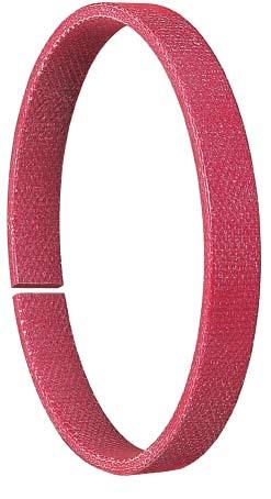
78 78

79 Guides Merkel Guivex SBK Guide Bush Applications Long-stroke cylinder (piston-rod deflection) Short guiding distance (piston-rod tilting) Short stroke (inappropriate lubrication) Frictionally optimized sealing systems Replacement for metallic guides Product description Profiled rod-type guide bush made of resin bonded fabric. Patented product design (patent No.: PCT/EP95/03874) Product advantages Intended, among others, for standardized housings as per ISO can replace current housings of type SB and SF high radial load capacity very good guide-length utilization based on uniform stress distribution enhanced penetration of lubricating media based on optimized stress distribution within the contact zone between the guide bush and the counter surface (favorable frictional behavior) reduced propensity for stick-slip excellent sliding behavior over a short guiding distance (no jamming) Material Material Designation Color Resin bonded fabric HGW HG650 red Field of application Guivex guide bushes can be used in all hydraulic fluids normally found in hydraulic systems such as oils and greases based on mineral oils, water, fireresistant hydraulic fluids (HFA, HFB, HFC, HFD) and biodegradable hydraulic fluids (HETG, HEES, HEPG). The maximum permissible operating temperature is 120 C Surface finish Peak-to-valley heights R a R max Sliding surface 0,05 0,3 µm <2,5 µm Groove base <1,6 µm <6,3 µm Groove sides <3,0 µm <15,0 µm Material content Mr >50% to max. 90% with cut depth c = Rz/2 and reference line Cref = 0% Resin bonded fabric HGW HG517 dark-gray The choice of material depends on the diameter involved. 79
80 uides Guides The long term behavior of a sealing element and its dependability against early failures are crucially influenced by the quality of the counterface. Therefore a precise description and assessment of the surface is critical. Based on recent findings, we recommend supplementing the above definition of surface finish for the sliding surface by the characteristics detailed in the table below. With these new characteristics derived from the material content, previous more general descriptions of the material content are significantly improved, especially in regard to surface roughness. See also Merkel Technical Manual.. (See section with additional information on surfaces and Merkel Technical Manual). Surface finish of the sliding surfaces Characteristic value Limit Ra > 0,05µm < 0,30µm Rmax Rpkx Rpk < 2,5µm < 0,5µm < 0,5µm Rk >0,25µm <0,7µm Rvk >0,2µm <0,65µm Rvkx >0,2µm <2,0µm The limit values listed in the table do not apply, at the present stage, to ceramic or partly ceramic counterfaces. Tolerances Diameter D1 H9 Manufacturing tolerances Profile thickness -0, ,06 The tolerance regarding diameters d and DF is determined in connection with the calculation of the gap dimension. Tolerance zones f7 and f8 and/or H7 and H8 are usually selected for typical hydraulic applications with a nominal size of up to 1,000mm. Surface load The value for the specific surface pressure depends on the operating temperature and the scope of elastic deformation (spring deflection) of the guiding element involved. The maximum possible spring deflection in a sealing system is limited by the minimum gap dimension downstream of the primary seal. (See Merkel Technical Manual) Spring deflection e1 = 0,1 at s = 2,5 e1 = 0,15 at s = 4 e2 = 0,15 at s = 2,5 e2 = 0,2 at s = 4 Spec. surface pressure (N/mm 2 ) Spec. surface pressure under parallel loads Design notes Diameter D1 indicated in the article list should be viewed solely in connection with the guide bush. The corresponding diameter of the connected seal housing must be in tune with the sealing element involved. Please note our general remarks on design in the Merkel Technical Manual Assembly Temperature ( C) Please note our general remarks on the assembly of hydraulic seals in the Merkel Technical Manual. 80
81 Side load Side loads within the contact area between the guide and the counter surface are not linear. The guiding width required can be calculated by applying the formulas indicated below on the basis of the projected area. The non-linear progression of side load pressures is taken into account in the contact pressure value. It may be advisable to reduce the loads by selecting a broader guide in individual cases to obtain an extended service life. F = P x A A = d x H H = F / (d x P) H = Guide bandwidth [mm] F = Radial loads [N] A = Projected area [mm²] P = perm. surface pressure [N/mm²] d = Rod diameter with rod guide; Piston diameter with piston guide [mm] Operating principle Rectangular guide bushes: Stress peaks within the edge area Guivex guide bush: uniform stress distribution 81
82 Guides Additional product description Guide strips Profiling Guivex guide bushes are provided with a convex profiling oriented towards the groove base. The side load applied is distributed evenly over the width of the guide element here. The maximum contact pressure value remains within the medium range and stress peaks on the edges are reduced (Figure 02). Side load The use of guide elements makes it possible to achieve low-friction and low-wear between the moving components of a hydraulic cylinder. Any side loads emerging during operation are absorbed effectively and any metal to metal contact between the piston rod and/or the piston barrel and the surrounding housing components is precluded. The scope of the maximum side load is essentially determined by the geometrical marginal conditions and the properties of the guide element involved. Excessive stresses The guide play and elastic deformation of the elements under load results in an angular deviation between the piston rod and/or the piston barrel and the counter surfaceduring operation. Consequently, guides inside hydraulic cylinders will not remain parallel, but primarily stressed at the edges. In this case, the permissible side load of the guide is defined by the lower maximum load up to edge break and not by the maximum compressive strength of the material. Excessive stresses within the edge area (Figure 01) make the penetration of lubricating media more difficult, too. The hydraulic medium is wiped along the edge stressed on the guide element and the lubricating film is reduced to a minimum, thus leading to stick-slip effects and greater wear. Figure 01: Rectangular guide bush Excessive stress within the edge area Figure 02: Guivex guide bush Uniform stress distribution Sliding properties Guivex guide bushes made of HGW HG517 and HGW HG 650 materials are compounded with graphite and/or PTFE in order to achieve a better dry-running behavior. As a result, guide bushes made of resin bonded fabric exhibit excellent sliding properties, due to the material properties alone, even in the event of inappropriate lubrication. The absorption of lubricating media within the area comprised between the guide and the counter surfaceis greatly enhanced by the patented profiling of Guivex guide bushes. Consequently, the sliding behavior is also improved by the Guivex geometry with correspondingly positive effects in terms of service life and stick-slip behavior. 82
83 Radial load capacity Merkel resin bonded fabric materials are characterized by a high degree of load capacity. The impact of the operating temperature on the load capacity of resin bonded fabric guide bushes is restricted, of course, when using duroplastic resin bonded fabric quality HGW HG517. The resin matrix of our material HGW HG650 includes both duroplastic and thermoplastic constituents. If permissible side loads are simultaneously less dependent on temperatures, the flexibility will be noticeably improved for assembly with small diameters. Purely thermoplastic basic materials like polyester, for example, exhibit a temperature-dependent material behavior. Permissible cross loads are greatly reduced under the effect of rising operating temperatures. (See Figure 03) HGW HG 517 HGW HG 650 other andere The absorption of lubricating media within the area comprised between the guide and the counter surfaceis greatly enhanced by the patented profiling of Guivex guide bushes. Consequently, Guivex guide bushes exhibit a favorable frictional behavior with correspondingly positive effects in terms of service life and stick-slip behavior. Forces are always introduced within the midsection of the guide bush. Uniform movements along the stroke, coupled with a high radial load capacity, can be achieved even in conjunction with short guide lengths and longstroke cylinders with the large angular offset to be expected. The system of guides inside the hydraulic cylinder will not be inclined to jam over a short guide distance either. The use of Guivex guide bushes makes a vital contribution to the functional reliability and dependability of hydraulic cylinders Querlast Side load C 80 C 100 C 120 C Figure 03: Resin bonded fabric materials in comparison of load capacity among plane-parallel guides depending on the operating temperature involved. Forces are always introduced within the medium range of the guide bush in conjunction with the patented Guivex geometry. The maximum permissible cross load is not reduced here by excess stress at the edges. Uniform movements along the stroke, coupled with a high radial load capacity, can be achieved even in conjunction with short guide lengths and long-stroke cylinders with high angular offset to be expected. 83
84 Guides All non-dimensioned edges rounded and burr-free ISO d D F D 1 L H Profile Material Article No ,6 9,7 9,5 2,5 HGW HG ISO ,6 9,7 9,5 2,5 HGW HG , ,8 2,5 HGW HG ISO ,6 9,7 9,5 2,5 HGW HG ISO ,6 9,7 9,5 2,5 HGW HG , ,8 2,5 HGW HG ,6 9,7 9,5 2,5 HGW HG , ,8 2,5 HGW HG ,6 9,7 9,5 2,5 HGW HG , ,8 2,5 HGW HG , ,8 4 HGW HG ,6 9,7 9,5 2,5 HGW HG , ,8 2,5 HGW HG ISO ,6 9,7 9,5 2,5 HGW HG , ,8 2,5 HGW HG ,6 9,7 9,5 2,5 HGW HG , ,8 2,5 HGW HG , ,5 2,5 HGW HG ISO ,6 9,7 9,5 2,5 HGW HG ISO , ,8 2,5 HGW HG , ,5 2,5 HGW HG ,6 9,7 9,5 2,5 HGW HG , ,8 2,5 HGW HG , ,5 2,5 HGW HG ISO ,6 9,7 9,5 2,5 HGW HG , ,5 2,5 HGW HG Further dimensions on request. 84
85 ISO d D F D 1 L H Profile Material Article No ,6 9,7 9,5 2,5 HGW HG , ,8 2,5 HGW HG ISO ,6 9,7 9,5 2,5 HGW HG ISO , ,8 2,5 HGW HG ,6 9,7 9,5 2,5 HGW HG , ,8 2,5 HGW HG ISO ,6 9,7 9,5 2,5 HGW HG ISO , ,8 2,5 HGW HG , ,5 4 HGW HG , ,8 2,5 HGW HG ,6 9,7 9,5 2,5 HGW HG , ,8 2,5 HGW HG , ,5 2,5 HGW HG ISO ,6 9,7 9,5 2,5 HGW HG ISO , ,8 2,5 HGW HG , ,5 2,5 HGW HG , ,8 2,5 HGW HG , ,5 4 HGW HG , ,8 2,5 HGW HG ISO ,6 9,7 9,5 2,5 HGW HG ISO , ,8 2,5 HGW HG , ,5 2,5 HGW HG , ,5 2,5 HGW HG , ,8 2,5 HGW HG , ,8 2,5 HGW HG , ,8 2,5 HGW HG x , ,8 2,5 HGW HG , ,5 2,5 HGW HG , ,8 2,5 HGW HG , ,5 2,5 HGW HG x ,6 9,7 9,5 2,5 HGW HG x , ,8 2,5 HGW HG , ,5 2,5 HGW HG , ,8 2,5 HGW HG , ,8 2,5 HGW HG , ,8 2,5 HGW HG x , ,8 2,5 HGW HG x , ,5 2,5 HGW HG Further dimensions on request. 85
86 Guides H L +0,2 R <0,3 1 Ø D F Ø D 1 Ø d All non-dimensioned edges rounded and burr-free ISO d D F D 1 L H Profile Material Article No , ,8 2,5 HGW HG ISO , ,8 2,5 HGW HG ISO , ,5 2,5 HGW HG , ,8 2,5 HGW HG , ,5 2,5 HGW HG , ,8 2,5 HGW HG , ,8 2,5 HGW HG ISO , ,8 2,5 HGW HG ISO , ,5 2,5 HGW HG , ,5 2,5 HGW HG ISO , ,8 2,5 HGW HG ISO , ,5 2,5 HGW HG , ,5 4 HGW HG , ,5 4 HGW HG , ,5 4 HGW HG , ,8 2,5 HGW HG , ,5 2,5 HGW HG , ,8 2,5 HGW HG ISO , ,5 2,5 HGW HG , ,5 2,5 HGW HG , ,5 4 HGW HG , ,5 4 HGW HG , ,5 4 HGW HG , ,5 2,5 HGW HG , ,5 4 HGW HG , ,8 2,5 HGW HG Further dimensions on request. 86
87 ISO d D F D 1 L H Profile Material Article No , ,5 4 HGW HG , ,5 4 HGW HG , ,5 2,5 HGW HG , ,5 4 HGW HG , ,5 4 HGW HG ISO , ,5 2,5 HGW HG , ,5 2,5 HGW HG ISO , ,5 4 HGW HG , ,5 4 HGW HG , ,8 2,5 HGW HG , ,5 4 HGW HG , ,5 4 HGW HG , ,5 2,5 HGW HG , ,5 4 HGW HG , ,5 4 HGW HG , ,5 2,5 HGW HG , ,8 2,5 HGW HG , ,5 2,5 HGW HG , ,5 2,5 HGW HG , ,5 4 HGW HG , ,5 4 HGW HG , ,8 2,5 HGW HG , ,5 2,5 HGW HG , ,5 4 HGW HG , ,5 2,5 HGW HG , ,5 4 HGW HG , ,5 4 HGW HG , ,5 2,5 HGW HG , ,5 4 HGW HG , ,5 4 HGW HG , ,5 4 HGW HG , ,5 4 HGW HG , ,5 2,5 HGW HG , ,5 4 HGW HG , ,8 2,5 HGW HG , ,5 4 HGW HG , ,5 4 HGW HG , ,5 2,5 HGW HG Further dimensions on request. 87
88 Guides H L +0,2 R <0,3 1 Ø D F Ø D 1 Ø d All non-dimensioned edges rounded and burr-free ISO d D F D 1 L H Profile Material Article No , ,8 4 HGW HG , ,5 4 HGW HG , ,5 4 HGW HG , ,5 4 HGW HG , ,5 2,5 HGW HG , ,5 4 HGW HG , ,5 2,5 HGW HG , ,5 4 HGW HG , ,5 4 HGW HG , ,5 4 HGW HG , ,5 4 HGW HG , ,5 2,5 HGW HG , ,5 4 HGW HG , ,5 4 HGW HG , ,5 4 HGW HG , ,5 4 HGW HG , ,5 4 HGW HG , ,5 4 HGW HG , ,5 4 HGW HG , ,5 2,5 HGW HG , ,5 4 HGW HG , ,5 4 HGW HG , ,8 2,5 HGW HG , ,5 4 HGW HG , ,5 4 HGW HG Further dimensions on request. 88
89 ISO d D F D 1 L H Profile Material Article No , ,8 4 HGW HG , ,5 4 HGW HG , ,5 4 HGW HG , ,5 4 HGW HG , ,5 4 HGW HG , ,5 4 HGW HG , ,5 4 HGW HG , ,8 4 HGW HG , ,5 4 HGW HG , ,5 2,5 HGW HG , ,5 2,5 HGW HG , ,5 4 HGW HG , ,5 4 HGW HG , ,5 4 HGW HG , ,5 4 HGW HG , ,8 4 HGW HG , ,5 4 HGW HG , ,5 4 HGW HG , ,5 4 HGW HG , ,5 4 HGW HG , ,5 4 HGW HG Further dimensions on request. 89
90 Guides Merkel SF Guide Ring Field of application Product description Non-metallic guide ring, either cut to size and ready for installation, or supplied as yard ware. Merkel SF Guide Ring can be used in all hydraulic fluids normally found in hydraulic systems such as oils and greases based on mineral oils, fireresistant hydraulic fluids (HFD) and biodegradable hydraulic fluids (HETG, HEES, HEPG). We do not recommend to used Guide Rings SF in water or water based fluids (HFA, HFB, HFC). The maximum permissible operating temperature is 120 C Surface finish Peak-to-valley heights R a R max Product advantages Non-metallic guide element for rods, for standardized housings as per ISO 10766, too low friction, stick-slip-free Material Material Designation Color PTFE-bronze compound PTFE B500 brown Sliding surface 0,05 0,3 µm <2,5 µm Groove base <1,6 µm <6,3 µm Groove sides <3,0 µm <15,0 µm Material content Mr >50% to max. 90% with cut depth c = Rz/2 and reference line Cref = 0% Design notes Please note our general remarks on design in the Merkel Technical Manual. Applications Injection molding machines, control and regulating instruments, hand-held equipment Manufacturing tolerance L2 Manufacturing tolerance > ,5 > ,0 > ,5 > ,0 > ,0 > ,0 90
91 Recommended tolerances The tolerance for dimensions d and D F must be viewed in connection with the seal used. Diameter D 1 stated in the table of dimensions must be considered exclusively in conjunction with the guide ring. The corresponding diameter of the connected seal housing has to be adapted to the sealing element involved. Profile thickness D 1 H8 Profile thickness S 0,05 Surface load Sliding speed, see sealing system. p <15 N/mm² 20 C p <7,5 N/mm² 80 C p <5 N/mm² 120 C Cutting rolls to size The dimensions indicated below are available as rolls ware from stock. Stretched length L2 of sections cut to size must be determined in line with the formula of calculation. Gap k arising after assembly is required for thermal expansion purposes. We recommend therefore that the strips be cut straight. Butt joint tips may be damaged by fissures. Our cutter (article N ) makes it possible to cut sections to size in a time-saving and accurate manner. Calculating stretched length L2 for pistons: L2 = (d + S) x 3,11 0,5 S H D L2 d Groove length L Strip thickness S Article No. 8 2, ,7 2, , , , , ,
92 Guides Surface force Pressure distribution over guide rings is not linear. The non-linear pressure progression within the contact area has been duly taken into account when determining the permissible specific surface contact pressure value. Permissible loads for guide strips are calculated by multiplying the projected area with the permissible specific surface contact pressure value. However, the angular offset of the piston likely to arise when using the recommended guide elements is duly taken into consideration in the permissible specific surface contact pressure value mentioned here. F = P x A A = d x H H = F / (d x P) H = Guide bandwidth [mm] F = Radial loads [N] A = Projected area [mm²] P = Perm. surface pressing value [N/mm²] d = Rod diameter with rod guide; piston diameter with piston guide [mm]. 92
93 H L +0,2 R <0,3 1 Ø D F Ø D 1 Ø d All non-dimensioned edges rounded and burr-free ISO d D F D 1 L H Profile Material Article No. ISO ,2 5,6 5,5 2,5 PTFE B ISO ,2 9,7 9,6 2,5 PTFE B , ,8 2,5 PTFE B ,2 9,7 9,6 2,5 PTFE B , ,8 2,5 PTFE B ,2 5,6 5,5 2,5 PTFE B ISO ,2 9,7 9,6 2,5 PTFE B , ,8 2,5 PTFE B ,2 9,7 9,6 2,5 PTFE B ,2 9,7 9,6 2,5 PTFE B , ,8 2,5 PTFE B ISO ,2 9,7 9,6 2,5 PTFE B , ,8 2,5 PTFE B ,2 9,7 9,6 2,5 PTFE B ISO ,2 9,7 9,6 2,5 PTFE B ,2 9,7 9,6 2,5 PTFE B , ,8 2,5 PTFE B ISO ,2 9,7 9,6 2,5 PTFE B ISO , ,8 2,5 PTFE B , ,5 PTFE B ,2 9,7 9,6 2,5 PTFE B , ,8 2,5 PTFE B ISO ,2 9,7 9,6 2,5 PTFE B ISO , ,8 2,5 PTFE B ,2 9,7 9,6 2,5 PTFE B ISO ,2 9,7 9,6 2,5 PTFE B Further dimensions on request. 93
94 Guides H L +0,2 R <0,3 1 Ø D F Ø D 1 Ø d All non-dimensioned edges rounded and burr-free ISO d D F D 1 L H Profile Material Article No. ISO , ,8 2,5 PTFE B , ,5 2,5 PTFE B , ,5 2,5 PTFE B , ,8 4 PTFE B ,2 9,7 9,6 2,5 PTFE B ISO ,2 9,7 9,6 2,5 PTFE B ISO , ,8 2,5 PTFE B , ,5 2,5 PTFE B , ,5 PTFE B , ,8 4 PTFE B ,2 9,7 9,6 2,5 PTFE B , ,5 2,5 PTFE B ,2 9,7 9,6 2,5 PTFE B , ,8 2,5 PTFE B ISO ,2 9,7 9,6 2,5 PTFE B ISO , ,8 2,5 PTFE B , ,5 2,5 PTFE B ,2 9,7 9,6 2,5 PTFE B , ,8 2,5 PTFE B , ,5 PTFE B ,2 9,7 9,6 2,5 PTFE B ISO , ,8 2,5 PTFE B , ,5 2,5 PTFE B , ,5 2,5 PTFE B , ,8 4 PTFE B ,2 9,7 9,6 2,5 PTFE B Further dimensions on request. 94
95 ISO d D F D 1 L H Profile Material Article No ,2 9,7 9,6 2,5 PTFE B ISO , ,8 2,5 PTFE B , ,5 PTFE B , ,5 4 PTFE B ,2 9,7 9,6 2,5 PTFE B , ,8 2,5 PTFE B , ,5 2,5 PTFE B ISO ,2 9,7 9,6 2,5 PTFE B ISO , ,8 2,5 PTFE B , ,5 2,5 PTFE B , ,8 2,5 PTFE B , ,5 2,5 PTFE B ,2 9,7 9,7 2,5 PTFE B , ,8 2,5 PTFE B , ,5 2,5 PTFE B , ,5 2,5 PTFE B ISO , ,8 2,5 PTFE B , ,8 2,5 PTFE B , ,5 PTFE B ISO , ,8 2,5 PTFE B , ,8 2,5 PTFE B , ,8 2,5 PTFE B , ,5 2,5 PTFE B , ,8 2,5 PTFE B , ,5 PTFE B , ,8 2,5 PTFE B , ,5 2,5 PTFE B , ,8 2,5 PTFE B , ,5 2,5 PTFE B , ,8 2,5 PTFE B , ,5 2,5 PTFE B , ,5 4 PTFE B x , ,8 2,5 PTFE B , ,5 4 PTFE B , ,8 2,5 PTFE B , ,5 2,5 PTFE B , ,5 4 PTFE B , ,5 PTFE B Further dimensions on request. 95
96 Guides H L +0,2 R <0,3 1 Ø D F Ø D 1 Ø d All non-dimensioned edges rounded and burr-free ISO d D F D 1 L H Profile Material Article No , ,5 2,5 PTFE B , ,8 2,5 PTFE B , ,5 2,5 PTFE B , ,8 2,5 PTFE B , ,5 2,5 PTFE B , ,5 4 PTFE B ISO , ,8 2,5 PTFE B , ,5 4 PTFE B , ,8 2,5 PTFE B , ,5 2,5 PTFE B , ,5 4 PTFE B , ,5 PTFE B , ,5 4 PTFE B , ,5 PTFE B , ,5 2,5 PTFE B , ,5 2,5 PTFE B , ,5 4 PTFE B , ,5 PTFE B , ,5 2,5 PTFE B , ,5 2,5 PTFE B , ,5 2,5 PTFE B , ,5 2,5 PTFE B , ,8 2,5 PTFE B , ,5 PTFE B , ,5 4 PTFE B , ,5 2,5 PTFE B Further dimensions on request. 96
97 ISO d D F D 1 L H Profile Material Article No , ,5 PTFE B ,6 0 24,5 2,5 PTFE B , ,5 4 PTFE B , ,5 2,5 PTFE B , ,5 4 PTFE B , ,5 PTFE B , ,5 4 PTFE B , ,5 PTFE B , ,8 2,5 PTFE B , ,5 2,5 PTFE B , ,5 4 PTFE B , ,5 2,5 PTFE B , ,5 2,5 PTFE B , ,5 2,5 PTFE B , ,5 PTFE B , ,5 4 PTFE B , ,5 4 PTFE B , ,5 2,5 PTFE B , ,5 4 PTFE B , ,5 PTFE B , ,8 2,5 PTFE B , ,5 2,5 PTFE B , PTFE B , ,8 4 PTFE B , ,5 4 PTFE B , ,5 4 PTFE B , ,5 2,5 PTFE B , ,5 4 PTFE B , ,5 4 PTFE B , ,5 2,5 PTFE B , ,5 4 PTFE B , ,5 4 PTFE B , ,5 2,5 PTFE B , ,5 4 PTFE B , ,5 4 PTFE B , ,5 4 PTFE B , PTFE B , ,5 4 PTFE B Further dimensions on request. 97
98 Guides H L +0,2 R <0,3 1 Ø D F Ø D 1 Ø d All non-dimensioned edges rounded and burr-free ISO d D F D 1 L H Profile Material Article No , ,5 2,5 PTFE B , ,5 4 PTFE B , ,5 4 PTFE B , ,5 2,5 PTFE B , ,5 4 PTFE B , ,5 4 PTFE B , ,5 2,5 PTFE B , ,5 4 PTFE B , ,5 4 PTFE B , ,5 4 PTFE B , PTFE B , ,5 4 PTFE B , ,5 4 PTFE B , ,5 4 PTFE B , ,5 4 PTFE B Further dimensions on request. 98
99 Merkel Guivex KBK Guide Bush Applications Long-stroke cylinder (piston-rod deflection) Short guiding distance (piston tilting) Short stroke (inappropriate lubrication) Frictionally optimized sealing systems Replacement for metallic guides Product description Profiled piston guide bush made of resin bonded fabric. Patented product design (patent No.: PCT/EP95/03874) Product advantages intended, among others, for standardized housings as per ISO interchangeable with current housings of type KB and KF high radial load capacity very good guide-length utilization based on uniform stress distribution enhanced penetration of lubricating media based on optimized stress distribution within the contact zone between the guide bush and the counter surface(favorable frictional behavior) reduced propensity for stick-slip excellent sliding behavior over a short guiding distance (no jamming) Field of application Guivex guide bushes can be used in all hydraulic fluids normally found in hydraulic systems such as oils and greases based on mineral oils, water, fireresistant hydraulic fluids (HFA, HFB, HFC, HFD) and biodegradable hydraulic fluids (HETG, HEES, HEPG). The maximum permissible operating temperature is 120 C Surface finish Peak-to-valley heights R a R max Sliding surface 0,05 0,3 µm <2,5 µm Groove base <1,6 µm <6,3 µm Groove sides <3,0 µm <15,0 µm Material content Mr >50% to max. 90% with cut depth c = Rz/2 and reference line Cref = 0% Material Material Designation Color Resin bonded fabric HGW HG650 red Resin bonded fabric HGW HG517 dark-gray The choice of material depends on the diameter involved. 99
100 Guides The long term behavior of a sealing element and its dependability against early failures are crucially influenced by the quality of the counterface. Therefore a precise description and assessment of the surface is critical. Based on recent findings, we recommend supplementing the above definition of surface finish for the dynamic surface by the characteristics detailed in the table below. With these new characteristics derived from the material content, previous more general descriptions of the material content are significantly improved, especially in regard to surface roughness. See also Merkel Technical Manual. Surface finish of the sliding surfaces Characteristic value Limit Ra > 0,05µm < 0,30µm Rmax Rpkx Rpk < 2,5µm < 0,5µm < 0,5µm Rk >0,25µm <0,7µm Rvk >0,2µm <0,65µm Rvkx >0,2µm <2,0µm The limit values listed in the table do not apply, at the present stage, to ceramic or partly ceramic counterfaces. Tolerances Diameter D1 h9 Manufacturing tolerances Profile thickness -0, ,06 The tolerance regarding diameters d F and D is determined in connection with the calculation of the gap dimension. Tolerance zones H7 and H8 and/or h7 and h8 are usually selected for typical hydraulic applications with a nominal size of up to 1,000mm. Surface load The value for the specific surface pressure depends on the operating temperature and the scope of elastic deformation (spring deflection) of the guiding element involved. The maximum possible spring deflection in a sealing system is limited by the minimum gap dimension downstream of the primary seal. (See also Merkel Technical Manual) Spring deflection e1 = 0,1 at s = 2,5 e1 = 0,15 at s = 4 e2 = 0,15 at s = 2,5 e2 = 0,2 at s = 4 Spec. surface pressure (N/mm 2 ) Design notes Temperature ( C) Spec. surface pressure under parallel loads Diameter d1 indicated in the table of dimensions should be viewed solely in connection with the guide bush. The corresponding diameter of the connected seal housing must be in tune with the sealing element involved. Installation & assembly Please note our general remarks on the installation of hydraulic seals in the Merkel Technical Manual. 100
101 Side load Pressure within the contact area between the guide and the counter surfaceis not linear. The guiding width required can be calculated by applying the formulas mentioned below on the basis of the projected area. The non-linear progression of the contact pressure process is taken into account in the surface pressure value. It may be advisable to reduce the loads by selecting a broader guide in individual cases to obtain an extended service life. F = P x A A = d x H H = F / (d x P) H = Guide bandwidth [mm] F = Radial loads [N] A = Projected area [mm²] P = perm. surface pressure [N/mm²] d = Rod diameter with rod guide; Piston diameter with piston guide [mm] Operating principle Rectangular guide bushes: Stress peaks within the edge area Guivex guide bush: uniform stress distribution 101

102 Guides Additional product description Guide strips Profiling Guivex guide bushes are provided with a convex profiling oriented towards the groove base. The side load applied is distributed evenly over the width of the guide element here. The maximum contact pressure value remains within the medium range and excessive stresses are reduced at the edges (Figure 02). Side load The use of guide elements makes it possible to achieve a low-friction and low-wear relative motion between the mobile components of the hydraulic cylinder. Any side loads arising during operation are absorbed effectively and any undesirable metal to metal contact between the piston rod and/or the piston barrel and the surrounding housing components is reduced. The scope of the maximum side load is essentially determined by the geometrical marginal conditions and the properties of the guide element involved. Excessive stresses The guide play and elastic deformation of the partners under loads result in an angular deviation between the piston rod and/or the piston barrel and the counter surfaceduring operation. Consequently, guides inside hydraulic cylinders will not be ideally parallel, but primarily stressed at the edges. In this case, the permissible side load of the guide is defined by the lower maximum load up to edge break and not by the maximum compressive strength of the material. Excessive stresses within the edge area (Figure 01) make the penetration of lubricating media more difficult, too. The hydraulic medium is wiped along the edge stressed on the guide element and the lubricating film is reduced to a minimum, thus leading to stick-slip effects and more significant wear. Figure 01: Rectangular guide bush Excessive stress within the edge area Figure 02: Guivex guide bush Uniform stress distribution Sliding properties Guivex guide bushes made of HGW HG517 and HGW HG 650 materials are compounded with graphite and/or PTFE in order to achieve a better dry-running behavior. As a result, guide bushes made of resin bonded fabric exhibit excellent sliding properties, due to the material properties alone, even in the event of inappropriate lubrication. The absorption of lubricating media within the area comprised between the guide and the counter surfaceis greatly enhanced by the patented profiling of Guivex guide bushes. Consequently, the sliding behavior is also improved by the Guivex geometry with correspondingly positive effects in terms of service life and stick-slip behavior. 102
103 Radial load capacity Merkel resin bonded fabric materials are characterized by a high degree of radial load capacity. The impact of the operating temperature on the load capacity of resin bonded fabric guide bushes is restricted, of course, when using duroplastic resin bonded fabric quality HGW HG517. The resin matrix of our material HGW HG650 includes both duroplastic and thermoplastic constituents. If permissible cross loads are simultaneously less dependent on temperatures, the flexibility will be tangibly enhanced for assembly with small diameters. Purely thermoplastic basic materials like polyester, for example, exhibit a temperature-dependent material behavior. Permissible cross loads are greatly reduced under the effect of rising operating temperatures. (See Figure 03). The absorption of lubricating media within the area comprised between the guide and the counter surfaceis greatly enhanced by the patented profiling of Guivex guide bushes. Consequently, Guivex guide bushes exhibit a favorable frictional behavior with correspondingly positive effects in terms of service life and stick-slip behavior. Forces are always introduced within the medium range of the guide bush. Uniform movements along the stroke, coupled with a high radial load capacity, can be achieved even in conjunction with short guide lengths and longstroke cylinders with the large angular offset to be expected. The system of guides inside the hydraulic cylinder will not be inclined to jam over a short guide distance either. The use of Guivex guide bushes makes a vital contribution to the functional reliability and dependability of hydraulic cylinders. Figure 03: Resin bonded fabric materials in comparison of load capacity among plane-parallel guides depending on the operating temperature involved. Forces are always introduced within the medium range of the guide bush in conjunction with the patented Guivex geometry. The maximum permissible cross load is not reduced here by excess stresses within the edge area. Uniform movements along the stroke, coupled with a high radial load capacity, can be achieved even in conjunction with short guide lengths and long-stroke cylinders with the large angular offset to be expected. 103
104 Guides All non-dimensioned edges rounded and burr-free ISO D d F d 1 L H Profile Material Article No ,4 9,7 9,5 2,5 HGW HG ,4 15,0 14,8 2,5 HGW HG ,4 9,7 9,5 2,5 HGW HG ,4 15,0 14,8 2,5 HGW HG ,4 9,7 9,5 2,5 HGW HG ,4 15,0 14,8 2,5 HGW HG ,4 9,7 9,5 2,5 HGW HG ,4 15,0 14,8 2,5 HGW HG ,4 9,7 9,5 2,5 HGW HG ,4 15,0 14,8 2,5 HGW HG ,4 9,7 9,5 2,5 HGW HG ,4 15,0 14,8 2,5 HGW HG ,4 9,7 9,5 2,5 HGW HG ,4 15,0 14,8 2,5 HGW HG ,4 9,7 9,5 2,5 HGW HG ,4 15,0 14,8 2,5 HGW HG ISO ,4 9,7 9,5 2,5 HGW HG ,4 15,0 14,8 2,5 HGW HG ,4 20,0 19,8 2,5 HGW HG ,4 9,7 9,5 2,5 HGW HG ,4 15,0 14,8 2,5 HGW HG ,4 9,7 9,5 2,5 HGW HG ,4 15,0 14,8 2,5 HGW HG ,4 9,7 9,5 2,5 HGW HG ,4 15,0 14,8 2,5 HGW HG ISO ,4 9,7 9,5 2,5 HGW HG Further dimensions on request. 104
105 ISO D d F d 1 L H Profile Material Article No ,4 15,0 14,8 2,5 HGW HG ,4 9,7 9,5 2,5 HGW HG ,4 20,0 19,8 2,5 HGW HG ,4 9,7 9,5 2,5 HGW HG ,4 15,0 14,8 2,5 HGW HG ,4 25,0 24,5 2,5 HGW HG ,4 15,0 14,8 2,5 HGW HG ,4 9,7 9,5 2,5 HGW HG ISO ,4 9,7 9,5 2,5 HGW HG ,4 15,0 14,8 2,5 HGW HG ,4 25,0 24,5 2,5 HGW HG ,4 9,7 9,5 2,5 HGW HG ,4 15,0 14,8 2,5 HGW HG ,4 25,0 24,5 2,5 HGW HG ,4 9,7 9,5 2,5 HGW HG ,4 15,0 14,8 2,5 HGW HG ISO ,4 9,7 9,5 2,5 HGW HG ISO ,4 15,0 14,8 2,5 HGW HG ,4 25,0 24,5 2,5 HGW HG ,4 25,0 24,5 2,5 HGW HG ,4 9,7 9,5 2,5 HGW HG ,4 9,7 9,5 2,5 HGW HG ISO ,4 9,7 9,5 2,5 HGW HG ISO ,4 15,0 14,8 2,5 HGW HG ,4 25,0 24,5 2,5 HGW HG ,4 15,0 14,8 2,5 HGW HG ,4 25,0 24,5 2,5 HGW HG ,4 9,7 9,5 2,5 HGW HG ,4 25,0 24,5 2,5 HGW HG ISO ,4 9,7 9,5 2,5 HGW HG ISO ,4 15,0 14,8 2,5 HGW HG ,4 9,7 9,5 2,5 HGW HG ,4 25,0 24,5 2,5 HGW HG ISO ,4 9,7 9,5 2,5 HGW HG ISO ,4 15,0 14,8 2,5 HGW HG ,4 20,0 19,8 2,5 HGW HG ,4 15,0 14,8 2,5 HGW HG ,4 15,0 14,8 2,5 HGW HG Further dimensions on request. 105
106 Guides All non-dimensioned edges rounded and burr-free ISO D d F d 1 L H Profile Material Article No ,4 25,0 24,5 2,5 HGW HG ,4 9,7 9,5 2,5 HGW HG ,4 25,0 24,5 2,5 HGW HG ISO ,4 9,7 9,5 2,5 HGW HG ISO ,4 15,0 14,8 2,5 HGW HG ,4 9,7 9,5 2,5 HGW HG ,4 25,0 24,5 2,5 HGW HG ISO ,4 9,7 9,5 2,5 HGW HG ISO ,4 15,0 14,8 2,5 HGW HG ,4 20,0 19,8 2,5 HGW HG ,4 15,0 14,8 2,5 HGW HG ,4 15,0 14,8 2,5 HGW HG ISO ,4 9,7 9,5 2,5 HGW HG ISO ,4 15,0 14,8 2,5 HGW HG ,4 15,0 14,8 2,5 HGW HG ,4 25,0 24,5 2,5 HGW HG ,4 9,7 9,5 2,5 HGW HG ,4 15,0 14,8 2,5 HGW HG ,4 15,0 14,8 2,5 HGW HG ,4 25,0 24,5 2,5 HGW HG ISO ,4 9,7 9,5 2,5 HGW HG ISO ,4 15,0 14,8 2,5 HGW HG ,4 15,0 14,8 2,5 HGW HG ,4 25,0 24,5 2,5 HGW HG ISO ,4 15,0 14,8 2,5 HGW HG ISO ,4 25,0 24,5 2,5 HGW HG Further dimensions on request. 106
107 ISO D d F d 1 L H Profile Material Article No ,4 15,0 14,8 2,5 HGW HG ,4 25,0 24,5 2,5 HGW HG ,4 15,0 14,8 2,5 HGW HG ,5 40,0 39,6 4 HGW HG ISO ,5 25,0 24,5 4 HGW HG ,4 30,0 29,5 2,5 HGW HG ,5 40,0 39,6 4 HGW HG ,4 15,0 14,8 2,5 HGW HG ,4 25,0 24,5 2,5 HGW HG ,5 25,0 24,5 4 HGW HG ,5 30,0 29,5 4 HGW HG ,5 25,0 24,5 4 HGW HG ,5 30,0 29,5 4 HGW HG ,4 15,0 14,8 2,5 HGW HG ,5 25,0 24,5 4 HGW HG ,5 40,0 39,5 4 HGW HG ISO ,4 25,0 24,5 2,5 HGW HG ISO ,5 25,0 24,5 4 HGW HG ,5 30,0 29,5 4 HGW HG ,5 40,0 39,6 4 HGW HG ,5 25,0 24,5 4 HGW HG ,4 25,0 24,5 2,5 HGW HG ,5 25,0 24,5 4 HGW HG ,5 25,0 24,5 4 HGW HG ,5 40,0 39,5 4 HGW HG ,4 25,0 24,5 2,5 HGW HG ,4 15,0 14,8 2,5 HGW HG ,4 15,0 14,8 2,5 HGW HG ,5 40,0 39,5 4 HGW HG ,5 40,0 39,5 4 HGW HG ,4 25,0 24,5 2,5 HGW HG ,5 25,0 24,5 4 HGW HG ,5 40,0 39,5 4 HGW HG ,5 40,0 39,5 4 HGW HG ,4 15,0 14,8 2,5 HGW HG ,5 25,0 24,5 4 HGW HG ,5 40,0 39,5 4 HGW HG ,5 40,0 39,5 4 HGW HG Further dimensions on request. 107
108 Guides All non-dimensioned edges rounded and burr-free ISO D d F d 1 L H Profile Material Article No ,5 25,0 24,5 4 HGW HG ,4 15,0 14,8 2,5 HGW HG ,4 25,0 24,5 2,5 HGW HG ,5 25,0 24,5 4 HGW HG ,5 40,0 39,6 4 HGW HG ,4 40,0 39,5 2,5 HGW HG ,4 25,0 24,5 2,5 HGW HG ,4 25,0 24,5 2,5 HGW HG ,4 25,0 24,5 2,5 HGW HG ,5 40,0 39,6 4 HGW HG ISO ,5 25,0 24,5 4 HGW HG ,5 40,0 39,5 4 HGW HG ,4 25,0 24,5 2,5 HGW HG ,5 25,0 24,5 4 HGW HG ,4 40,0 39,5 2,5 HGW HG ,5 25,0 24,5 4 HGW HG ,5 40,0 39,5 4 HGW HG ,4 25,0 24,5 2,5 HGW HG ,5 25,0 24,5 4 HGW HG ,5 40,0 39,5 4 HGW HG ,4 25,0 24,5 2,5 HGW HG ,5 40,0 39,5 4 HGW HG ,5 40,0 39,5 4 HGW HG ,5 20,0 19,8 4 HGW HG ,5 40,0 39,5 4 HGW HG ,4 25,0 24,5 2,5 HGW HG Further dimensions on request. 108

109 ISO D d F d 1 L H Profile Material Article No ,4 25,0 24,5 2,5 HGW HG ,5 25,0 24,5 4 HGW HG ,5 40,0 39,5 4 HGW HG ,5 40,0 39,5 4 HGW HG ,5 25,0 24,5 4 HGW HG ,4 25,0 24,5 2,5 HGW HG ,5 40,0 39,5 4 HGW HG ,5 25,0 24,5 4 HGW HG ,5 40,0 39,5 4 HGW HG ,4 25,0 24,5 2,5 HGW HG ,5 25,0 24,5 4 HGW HG ,4 25,0 24,5 2,5 HGW HG ,5 25,0 24,5 4 HGW HG ,5 40,0 39,5 4 HGW HG ,4 15,0 14,8 2,5 HGW HG ,5 35,0 34,5 4 HGW HG ,4 40,0 39,5 2,5 HGW HG ,5 40,0 39,5 4 HGW HG ,5 40,0 39,5 4 HGW HG ,5 25,0 24,5 4 HGW HG ,5 35,0 34,5 4 HGW HG ,5 25,0 24,5 4 HGW HG ,5 40,0 39,5 4 HGW HG ,5 20,0 19,8 4 HGW HG ,5 25,0 24,5 4 HGW HG ,5 25,0 24,5 4 HGW HG ,5 25,0 24,5 4 HGW HG ,5 25,0 24,5 4 HGW HG ,5 20,0 19,8 4 HGW HG ,5 40,0 39,5 4 HGW HG ,5 40,0 39,5 4 HGW HG ,5 25,0 24,5 4 HGW HG ,5 40,0 39,5 4 HGW HG ,5 25,0 24,5 4 HGW HG ,5 40,0 39,5 4 HGW HG Further dimensions on request. 109
110 Guides Merkel KF Guide Ring Field of application Product description Non-metallic guide ring, either cut to size and ready for installation, or supplied as rolls. Product advantages Non-metallic guide element for pistons, for standardized housings as per ISO 10766, too low friction, stick-slip-free Material Material Designation Color PTFE-bronze compound Applications PTFE B500 brown Injection molding machines, control and regulating instruments, hand-held equipment Merkel KF Guide Rings can be used in all hydraulic fluids normally found in hydraulic systems such as oils and greases based on mineral oils, fireresistant hydraulic fluids (HFD) and biodegradable hydraulic fluids (HETG, HEES, HEPG). We do not recommend to used Guide Rings SF in water or water based fluids (HFA, HFB, HFC). The maximum permissible operating temperature is 120 C Surface finish Peak-to-valley heights Sliding surface Design notes Please note our general remarks on design in the Merkel Technical Manual. Manufacturing tolerance L2 Manufacturing tolerances > ,5 > ,0 > ,5 > ,0 > ,0 > ,0 R a 0,05 0,3 µm R max <2,5 µm Groove base <1,6 µm <6,3 µm Groove sides <3,0 µm <15,0 µm Material content Mr >50% to max. 90% with cut depth c = Rz/2 and reference line Cref = 0% 110
111 Recommended tolerances d 1 h8 The tolerance for dimensions D and d F must be viewed in connection with the seal used. Diameter d1 stated in the table of dimensions must be considered exclusively in conjunction with theguide ring. The corresponding diameter of the connected seal housing has to be adapted to the sealing element invol ved. Profile thickness Profile thickness S 0,05 Surface load Sliding speed, see sealing system. p <15 N/mm² 20 C p <7,5 N/mm² 80 C p <5 N/mm² 120 C Cutting rolls to size The dimensions indicated below are available as rolls from stock. Stretched length L2 of sections cut to size must be determined in line with the formula of calculation. Gap k arising after assembly is required for thermal expansion purposes. We recommend therefore that the strips be cut straight. Butt joint tips may be damaged by fissures. Our cutter (article N ) makes it possible to cut sections to size in a time-saving and accurate manner. Calculating stretched length L2 for pistons: L2 = (D S) x 3,11 0,5 S H D L2 d Groove length L Strip thickness S Article No. 8 2, ,7 2, , , , , ,
112 Guides Surface force Pressure within the contact area between the guide and the counter surfaceis not linear. The guiding width required can be calculated by applying the formulas mentioned below on the basis of the projected area. The non-linear progression of the contact pressure process is taken into account in the surface pressure value. It may be advisable to reduce the loads by selecting a broader guide in individual cases to obtain an extended service life. F = P x A A = d x H H = F / (d x P) H = Guide bandwidth [mm] F = Radial loads [N] A = Projected area [mm²] P = perm. surface pressure [N/mm²] d = Rod diameter with rod guide; Piston diameter with piston guide [mm] 112
113 H L +0,2 R < = 0,3 1 Ø D Ø d 1 Ø d F All non-dimensioned edges rounded and burr-free ISO D d F d 1 L H Profile Material Article No ,8 5,6 5,5 2,5 PTFE B ,8 5,6 5,5 2,5 PTFE B ,8 5,6 5,5 2,5 PTFE B ,8 9,7 9,6 2,5 PTFE B ISO ,8 9,7 9,6 2,5 PTFE B ,8 9,7 9,6 2,5 PTFE B ,8 9,7 9,6 2,5 PTFE B , ,8 2,5 PTFE B ,8 9,7 9,6 2,5 PTFE B ISO ,8 9,7 9,6 2,5 PTFE B ,8 9,7 9,6 2,5 PTFE B , ,8 2,5 PTFE B ,8 9,7 9,6 2,5 PTFE B , ,8 2,5 PTFE B , ,5 2,5 PTFE B ,8 9,7 9,6 2,5 PTFE B , ,8 2,5 PTFE B ISO ,8 9,7 9,6 2,5 PTFE B , ,8 2,5 PTFE B , ,5 2,5 PTFE B ,8 9,7 9,6 2,5 PTFE B , ,5 2,5 PTFE B ,8 9,7 9,6 2,5 PTFE B , ,8 2,5 PTFE B , ,5 2,5 PTFE B ,8 9,7 9,6 2,5 PTFE B Further dimensions on request. 113
114 Guides H L +0,2 R < = 0,3 1 Ø D Ø d 1 Ø d F All non-dimensioned edges rounded and burr-free ISO D d F d 1 L H Profile Material Article No ,8 9,7 9,6 2,5 PTFE B , ,8 2,5 PTFE B ISO ,4 9,7 9,6 2,5 PTFE B , ,8 2,5 PTFE B ,8 9,7 9,6 2,5 PTFE B , ,8 2,5 PTFE B , ,5 2,5 PTFE B ,8 9,7 9,6 2,5 PTFE B , ,8 2,5 PTFE B ISO ,8 9,7 9,6 2,5 PTFE B ISO , ,8 2,5 PTFE B , ,5 2,5 PTFE B , ,5 2,5 PTFE B ,8 9,7 9,6 2,5 PTFE B , ,8 2,5 PTFE B , ,5 2,5 PTFE B , ,5 2,5 PTFE B ,8 9,7 9,6 2,5 PTFE B ISO ,8 9,7 9,6 2,5 PTFE B ISO , ,8 2,5 PTFE B , ,5 2,5 PTFE B ,8 9,7 9,6 2,5 PTFE B , ,8 2,5 PTFE B , ,5 2,5 PTFE B ISO ,8 9,7 9,6 2,5 PTFE B ISO , ,8 2,5 PTFE B Further dimensions on request. 114
115 ISO D d F d 1 L H Profile Material Article No , ,5 2,5 PTFE B ,4 9,7 9,6 2,5 PTFE B , ,8 2,5 PTFE B , ,5 2,5 PTFE B , ,5 2,5 PTFE B , ,5 2,5 PTFE B , ,8 2,5 PTFE B ISO ,4 9,7 9,6 2,5 PTFE B ISO , ,8 2,5 PTFE B , ,5 2,5 PTFE B , ,8 2,5 PTFE B , ,5 2,5 PTFE B , ,8 2,5 PTFE B , ,5 2,5 PTFE B ISO , ,8 2,5 PTFE B , ,5 2,5 PTFE B ISO , ,5 2,5 PTFE B , ,5 2,5 PTFE B , ,8 2,5 PTFE B , ,5 2,5 PTFE B , ,8 2,5 PTFE B , ,5 2,5 PTFE B , ,5 4 PTFE B ISO , ,8 2,5 PTFE B , ,5 2,5 PTFE B ISO , ,5 2,5 PTFE B , ,8 2,5 PTFE B , ,5 2,5 PTFE B , ,8 2,5 PTFE B , ,5 2,5 PTFE B ,4 9,7 9,6 2,5 PTFE B , ,8 2,5 PTFE B , ,5 2,5 PTFE B , ,8 4 PTFE B x , ,5 4 PTFE B x , ,8 2,5 PTFE B x , ,5 2,5 PTFE B , ,5 2,5 PTFE B Further dimensions on request. 115
116 Guides H L +0,2 R < = 0,3 1 Ø D Ø d 1 Ø d F All non-dimensioned edges rounded and burr-free ISO D d F d 1 L H Profile Material Article No , ,8 2,5 PTFE B , ,5 2,5 PTFE B , ,8 2,5 PTFE B , ,5 2,5 PTFE B ,4 9,7 9,6 2,5 PTFE B , ,8 2,5 PTFE B , ,5 2,5 PTFE B , ,8 4 PTFE B ISO , ,5 4 PTFE B ISO , ,8 2,5 PTFE B ISO , ,5 2,5 PTFE B , ,5 2,5 PTFE B , ,5 2,5 PTFE B , ,5 4 PTFE B , ,5 2,5 PTFE B , ,5 2,5 PTFE B ISO , ,5 4 PTFE B ISO , ,8 2,5 PTFE B , ,5 2,5 PTFE B ISO , ,5 2,5 PTFE B , ,5 2,5 PTFE B , ,5 2,5 PTFE B , ,5 2,5 PTFE B , ,8 2,5 PTFE B , ,5 2,5 PTFE B , ,8 2,5 PTFE B Further dimensions on request. 116
117 ISO D d F d 1 L H Profile Material Article No. ISO , ,5 4 PTFE B ISO , ,8 2,5 PTFE B ISO , ,5 2,5 PTFE B , ,8 2,5 PTFE B , ,5 2,5 PTFE B , ,5 2,5 PTFE B , ,8 2,5 PTFE B , ,5 2,5 PTFE B , ,5 2,5 PTFE B , ,5 2,5 PTFE B , ,5 4 PTFE B , ,8 2,5 PTFE B , ,5 2,5 PTFE B , ,8 4 PTFE B , ,5 4 PTFE B , ,8 4 PTFE B , ,5 2,5 PTFE B , ,5 4 PTFE B , ,8 2,5 PTFE B , ,5 2,5 PTFE B , ,5 2,5 PTFE B , ,8 2,5 PTFE B , ,8 2,5 PTFE B , ,5 2,5 PTFE B , ,5 4 PTFE B , ,5 4 PTFE B , ,5 2,5 PTFE B , ,5 2,5 PTFE B , ,5 2,5 PTFE B , ,8 4 PTFE B , ,5 4 PTFE B , ,5 2,5 PTFE B , ,5 4 PTFE B , ,5 4 PTFE B , ,8 2,5 PTFE B , ,5 2,5 PTFE B , ,5 2,5 PTFE B , ,5 4 PTFE B Further dimensions on request. 117
118 Guides H L +0,2 R < = 0,3 1 Ø D Ø d 1 Ø d F All non-dimensioned edges rounded and burr-free ISO D d F d 1 L H Profile Material Article No , ,5 4 PTFE B , ,8 2,5 PTFE B , ,5 2,5 PTFE B , ,5 2,5 PTFE B , ,5 2,5 PTFE B , ,5 4 PTFE B , ,8 4 PTFE B , ,5 4 PTFE B , ,5 2,5 PTFE B , ,8 4 PTFE B , ,5 2,5 PTFE B , ,8 2,5 PTFE B , ,8 4 PTFE B , ,5 4 PTFE B , ,5 4 PTFE B , ,5 4 PTFE B , ,5 2,5 PTFE B , ,5 4 PTFE B , ,5 2,5 PTFE B , ,5 2,5 PTFE B , ,5 4 PTFE B , ,5 4 PTFE B , ,5 2,5 PTFE B , ,5 2,5 PTFE B , ,5 4 PTFE B , ,5 2,5 PTFE B Further dimensions on request. 118

119 ISO D d F d 1 L H Profile Material Article No , ,8 4 PTFE B , ,5 4 PTFE B , ,5 2,5 PTFE B Further dimensions on request. 119
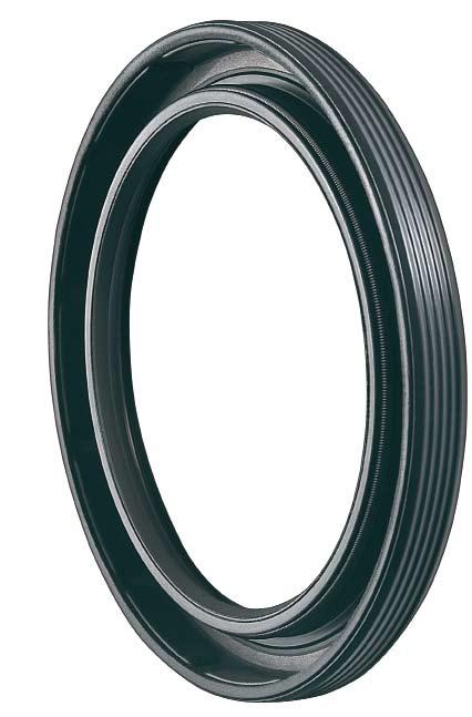
120 120
121 Shaft seals Simmerring BAUMSL X7 Material Fluoroelastomer Color Designation Hardness Spring Reinforcing plate 75 FKM 585 darkbrown Shore A 75 ore A Spring steel DIN EN unalloyed steel DIN EN Product description Outer sleeve: elastomer, grooved, spring-loaded sealing lip, additional dust lip, frictionally optimized sealing lip profile. Applications Agricultural and construction machinery Industrial gears Axles (exposed to moderate dirt influences) Electric tools Product advantages broad application spectrum in all branches of industry greater thermal stability and chemical resistance Secure OD sealing, even in the event of higher bore roughness, thermal expansion and spilt housings, so that fluid and gaseous media can be sealed, too. advantages for sealing against fluid and gaseous media additional dust lip protecting against reasonable and average volumes of dust and dirt from outside (note: may lead to higher temperatures as a result of frictional heat) 121
122 haft seals Shaft seals Media Temperature Mineral oils, synthetic oils, aromatic and chlorinated hydrocarbons, motor fuels, heating oils C Speed [U/min] Peripheral speed [m/s] Peripheral v speed Shaft diameter [mm] Permissible peripheral speed for Simmerrings made of materials NBR (72 NBR 902) and FKM (75 FKM 585) for sealing motor oil SAE 20. Use of a Simmerring with a DL (dirt lip): v = max. 8 m/s Pressure up to 0.05 MPa/0.5 bar a Simmerring provided with a back-up ring can be used at >0.05 MPa/0.5 bar. See also Simrit Technical Manual. Shaft Tolerance Concentricity Roughness Hardness Finish ISO h 11 IT 8 R a = 0,2 0,8 µm; R z = 1,0 5,0 µm; R max = <6,3 µm HRC non oriented, preferably by plunge grinding Housing bore Tolerance Roughness ISO H8 R z = µm For optimum seal performance correct handling and installation is critical as per DIN3760. See also Simrit Technical Manual. 122
123 min=b + 0,3 b Ø d2 H8 Ø d2 Ø d1 Ø d1h11 d 1 d 2 b DIN 3761 Article No ,5 AS AS AS AS AS AS AS AS AS AS AS AS AS AS AS AS AS AS AS AS AS AS AS AS AS AS AS AS AS Further dimensions on request. 123
124 Shaft seals min=b + 0,3 b Ø d2 H8 Ø d2 Ø d1 Ø d1h11 d 1 d 2 b DIN 3761 Article No AS AS AS AS AS AS AS AS AS AS AS AS AS AS AS AS AS AS AS AS AS AS AS AS AS AS AS AS AS Further dimensions on request. 124
125 d 1 d 2 b DIN 3761 Article No AS AS AS AS AS AS AS AS AS AS AS AS AS AS AS AS AS AS AS AS AS AS AS AS AS AS AS AS AS AS AS AS Further dimensions on request. 125
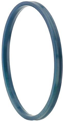
126 126
 30 +60 C Mineral greases 30 +100 C Product description Single-piece, double-acting compact seal made of Polyurethane for link-pin sealing purposes, internal sealing.")
127 Link-pin sealing Merkel Pinmatic Polyurethane profile ring Field of application Medium Material 95 AU V142 Hydraulic oils HL, HLP C HETG (rape-seed oil) C HEES (synth. ester) C Mineral greases C Product description Single-piece, double-acting compact seal made of Polyurethane for link-pin sealing purposes, internal sealing. Product advantages loss-free lubricant supply to link-pin bearings requiring restricted maintenance great functional reliability minimum wear stable long-term behavior extended service intervals insensitive to pressure peaks The newly developed Merkel Pinmatic seal is ideally suited for meeting the demands made on a link-pin seal. The excellent functional reliability based on a given circulation and/or pulse lubrication is achieved on the basis of the appropriate extrusion resistance of the material Polyurethane as well as the high line force along the sealing edge. Material Material Designation Color Polyurethane 95 AU V142 dark-blue Application Swiveling movement, pressure peaks, injection molding machines, toggles, bearing and link pins Pressure Speed (swiveling movement) Surface finish Peak-to-valley heights 2 MPa 0,2 m/s The long term behavior of a sealing element and its dependability against early failures are crucially influenced by the quality of the counterface. Therefore a precise description and assessment of the surface is critical. Based on recent findings, we recommend supplementing the above definition of surface finish for the dynamic surface by the characteristics detailed in the table below. With these new characteristics derived from the material content, previous more general descriptions of the material content are significantly improved, especially in regard to surface roughness. See also Merkel Technical Manual. R a R max Sliding surface <0,8 µm <3,2 µm Groove base <1,6 µm <6,3 µm Groove sides <6,3 µm <20 µm Lead-in chamfer* <0,8 µm <3,2 µm * burr-free transition 127
128 ink-pin ealing Link-pin sealing Surface finish of the sliding surfaces Characteristic value Limit Ra > 0,05µm < 0,30µm Rmax < 2,5µm Rpkx < 0,5µm Rpk < 0,5µm Rk >0,25µm <0,7µm Rvk >0,2µm <0,65µm Rvkx >0,2µm <2,0µm Gap dimension Section Max. permissible gap dimension at 2 MPa 3,5-8,5 0,55 Recommended tolerances Diameter Tolerance < 200 H7/f7 Design notes Please note our general design-related remarks in the Merkel Technical Manual. Installation & assembly Please note our general remarks on the installation of hydraulic seals in the Merkel Technical Manual, Assembling hydraulic seals. 128
129 Additional product description Pinmatic relaxed state ensures reliable sealing properties at standstill and, therefore, clean conditions. The Pinmatic profile is designed on the basis of FEM calculations while considering the pressure applied to the housing. Pinmatic is designed individually in line with the metallic housing involved. A constantly high degree of functional reliability is set regardless of the tolerances of the metallic components. It is possible to apply application experiences gathered with one scope of diameters directly to another scope of diameters, when designing series. Application A sealing system integrated into the bearing shells and preventing lubricant leakage in a reliable way has been specially developed for toggle-lever systems on injection molding machines. Toggle-lever machines provide special benefits in certain applications. Toggle-lever bearings being exposed to heavy loads must, however, be reliably lubricated. Leaking lubricant has frequently been leading to considerable soiling so far. There is hardly any production environment nowadays where this is acceptable. The new bearing system integrates single-piece, double-acting Pinmatic compact seals made of polyurethane into two bearing-shell grooves. This prevents lubricants from leaking between the link pin and the togglelever bearing. As a result, the machine will remain clean and maintenance operations will be reduced due to leak-free lubricant supply. The line force defined within the sealing edge area makes it possible to achieve a high degree of functional reliability under any operating conditions. The Pinmatic profile ring is clearly preferred due to the stable support provided in the groove bottom. Any squeezing movements occurring inside the sealing ring in the event of rotational direction changes as well as a helical distortion of the sealing ring during assembly are precluded, thus providing enhanced functional reliability. The use of Pinmatic makes a vital contribution to the dependable sealing of plain bearings in toggle levers and, therefore, to a clean exterior of the machine as a whole. Pressing and friction Sealing elements made of polyurethane make it possible to achieve an efficient sealing effect, due to the material properties provided. The sealing material is interlinked to different degrees with the counterface, depending on the contact force and the size of the contact face involved. The closer the contact, the higher the coefficient of friction will be. Link-pin seals made from polyurethane 95AUV142 exhibit restricted friction only, no stick-slip effect and minimum wear. The strong line force also exerted on the sealing edge in the 129
130 Link-pin sealing d D S H L C R Material Article No ,5 2,9 3,5 3,5 0,4 95 AU V ,5 2,9 3,5 3,5 0,4 95 AU V ,5 2,9 3,5 3,5 0,4 95 AU V ,5 2,9 3,5 3,5 0,4 95 AU V ,2 5 4,5 0,6 95 AU V ,2 5 4,5 0,6 95 AU V ,2 5 4,5 0,6 95 AU V ,2 5 4,5 0,6 95 AU V ,5 4, ,6 95 AU V ,5 5, ,6 95 AU V ,5 5, ,6 95 AU V ,5 5, ,6 95 AU V Further dimensions on request. 130
131 Merkel Cover Seal PU 82 Polyurethane profile ring Product description Single-piece, double-acting compact seal made of Polyurethane for static sealing, internal sealing. Product advantages interchangeable with housings for O-ring and O-ring with back-up ring high degree of functional reliability provided by the sturdy profile ring made of Polyurethane great resistance to extrusion (dimensional stability) simple and safe assembly (single-piece element) simplified inventory gastight Field of application Material 95 AU V142/94 AU 925 Hydraulic oils, HL, HLP C HFA fluids C HFB fluids C HFC fluids C HFD fluids - Water C HETG (rape-seed oil) C HEES (synth. ester) C HEPG (glycol) C Mineral greases C Pressure 60 MPa The figures given are maximum values and must not be applied simultaneously. Surface finish Peak-to-valley heights R a R max Sliding surface <0,8 µm <3,2 µm Groove base <1,6 µm <6,3 µm Groove sides <6,3 µm <20 µm Lead-in chamfer* <0,8 µm <3,2 µm * burr-free transition Gap dimension Material The maximum permissible extrusion gap with a piston rod arranged on one side, while taking cylinder Material Designation Color expansion into account, is determined, to a Polyurethane 95 AU V142 dark-blue large extent, by the maximum operating pressure Polyurethane 94 AU 925 light-blue and the dimensional stability of the sealing material, depending on the temperature involved. Der Material wird durch den NennDiameter und das Fertigungsverfahren bestimmt. Section* Max. perm. gap dimension Applications High operating pressure (up to 60 MPa) Breathing gap (cylinder expansion) Short pressure build-up time (end-of-travel damping) Reciprocal operating pressure Nominal diameter up to 2,000mm 16 MPa 26 MPa 32 MPa 40 MPa 60 MPa 1,78 0,2 0,2 0,15 0,1 0,1 2,62 0,35 0,3 0,25 0,15 0,1 3,5/3,53 0,5 0,4 0,35 0,25 0,2 5,33 0,5 0,4 0,35 0,25 0,2 6,99/7 0,55 0,45 0,35 0,35 0,25 8 0,55 0,45 0,4 0,35 0,25 8,4 0,55 0,45 0,4 0,35 0, ,6 0,5 0,45 0,4 0,3 12 0,6 0,5 0,45 0,4 0,3 * Cord thickness for housing recommendation O-ring with a back-up ring 131
132 Static seal Tolerances Diameter d Tolerance < 800 H7/f7 > ,1 / -0,05 / -0,15 Operating principle O-ring with a PTFE back-up ring at an operating pressure of 40 MPa Design notes Please note our general remarks in the Merkel Technical Manual. Installation & assembly Please note our general remarks on the installation of hydraulic seals in the Merkel Technical Manual. 132
133 Additional product description Cover Seal PU 82 O-ring and back-up ring Static sealing is usually achieved by combining an O-ring and a back-up ring for operation at a pressure exceeding 15 MPa and for pressurization on one side. At higher operating pressures, the back-up ring function is restricted by the resulting tube expansion. This causes damage to the O- ring as well as the back-up ring, as a result of gap extrusion. Two back-up rings are required in the event of alternate pressurization. Under such operating conditions, O-rings are frequently twisted inside the groove until the sealing element fails. A series of possible defects likely to jeopardize the lasting functionality of the sealing element also arise during installation and operation of the combined O-ring and back-up ring. into the sealing gap arising under pressure. If the pressure drops suddenly, the extrusion lug may be sheared off as a result. In this case, the elastic deformation of the metal (cylinder expansion) is reduced within a shorter period of time than that required by the O-ring to get out of the gap. The gap resulting from the manufacturing tolerances of the back-up ring on the side facing the groove bottom represents a further source of defects in terms of damage caused by extrusion to the O-ring (Figure 02). The cover seal is subject to comparatively moderate deformations only at high operating pressures (Figure 03). The element bridges the extrusion gap, but does not penetrate into it. The deformation is entirely reversible. Figure 01: PTFE back-up ring at 40 MPa Figure 02: PA back-up ring at 20 MPa Cylinder expansion A conventional back-up ring fills the gap to the main functional surface in pressureless condition. Back-up rings are made either of virgin PTFE or more dimensionally stable materials like PA, for example. Pure PTFE tends to creep under the effects of lengthy stresses. The back-up ring adapts itself to the housing, while filling the gap. At high pressure, the surfaces to be sealed are moved as a result of cylinder expansion. The PTFE back-up ring penetrates into the sealing gap and is squeezed when relieved (Figure 01). Dimensionally stable PA back-up rings are only slightly distorted under pressure and fail, therefore, to adapt their shape to the housing. The O-ring may penetrate Figure 03: Cover seal at 40 Ma Pressure The radial deformation of the sealing element inside the housing is an indicator for the sealing effect. Whereas insufficient pressure reduces both the initial sealing effect in pressureless condition and the suitability for short pressure build-up periods, excessive pressure may lead to a shorter service life as a result of material fatigue. 133
134 Static seal The tolerances for metallic components and the seal exert a profound influence on profile overlapping. Whereas tolerance dimensions for metallic components are selected according to the nominal diameter involved, the cord thickness for an O- ring is given a constant tolerance regardless of the O-ring diameter. The larger the nominal diameter with the same cord thickness, the larger possible deviations from ideal pressure conditions will be. The sealing effect and/or the functional reliability of an O-ring will decline in proportion to nominal diameter increases. The cover seal profile is adapted to the housing respectively involved, i.e. by taking the nominal diameter into consideration, too, on the basis of a design program and in view of the pressing conditions. Consequently, the diameter has no impact on the sealing effect and functional reliability. The cover seal is designed individually in line with the metallic housing used. A continously high degree of functional reliability is set regardless of the tolerances of the metallic components and of the nominal diameter involved. It is possible to apply application experiences gathered with one scope of diameters directly to another scope of diameters, when designing series. A high degree of functional reliability is attained under any operating conditions due to a great resistance to extrusion and a favorable mold release behavior, on the one hand, and to the high line force around the sealing edge even in pressureless condition, on the other. The profile ring of the cover seal is clearly preferred due to the stable support provided in the groove bottom. Any squeezing and rotary movements occurring inside the sealing ring under changing pressure as well as a helical distortion of the sealing ring during assembly are precluded, thus providing enhanced functional reliability. The single-piece symmetrical cover seal design precludes any faulty installation due to twisting or confusion. Procurement and storing are simplified by the use of the single-piece cover seal. The use of the cover seal makes a vital contribution to the functional reliability and dependability of hydraulic cylinders. 134
135 d D S H L C R Material Article No ,6 6,4 3,5 0,4 95 AU V ,2 10,5 4,5 0,4 95 AU V ,6 2,75 4,4 5,2 3,0 0,4 95 AU V ,6 2,8 5,3 6,2 3,0 0,4 95 AU V ,5 2,6 3,2 3,0 0,4 95 AU V ,2 10,5 4,5 0,4 95 AU V ,8 12,3 8,0 0,4 95 AU V ,5 4 4,7 3,0 0,4 95 AU V ,8 12,3 8,0 0,6 95 AU V ,9 2,95 4,9 5,8 3,5 0,6 95 AU V ,6 4,3 7,8 9 4,0 0,6 95 AU V ,3 3,15 4,9 5,8 3,5 0,6 95 AU V ,6 4,3 7,8 9 4,0 0,4 95 AU V ,6 5,8 10,7 12,3 5,0 0,6 94 AU ,6 4,3 7,8 9 4,0 0,6 95 AU V ,6 5,8 10,7 12,3 5,0 0,6 94 AU ,1 4,55 5,2 6,1 4,5 0,6 95 AU V ,4 4,7 6,1 7,1 4,0 0,6 95 AU V ,6 4,3 7,8 9 4,0 0,6 95 AU V ,6 5,8 10,9 12,3 4,5 0,6 94 AU ,2 4,1 7,4 8,5 3,5 0,6 95 AU V ,6 4,3 7,8 9 4,0 0,6 94 AU ,6 5,8 10,4 12 5,0 0,6 95 AU V , ,0 0,4 94 AU ,6 5,8 10,7 12,3 5,0 0,6 94 AU ,8 4,9 7,1 8,2 4,0 0,4 95 AU V Further dimensions on request. 135
136 Static seal d D S H L C R Material Article No ,6 5,8 10,4 12 5,0 0,6 95 AU V ,6 5,8 10,7 12,3 5,0 0,6 95 AU V ,6 5,8 10,9 12,3 4,5 0,4 94 AU ,4 6,7 8,6 10 6,0 0,6 95 AU V ,6 5,8 10,7 12,3 5,0 0,6 94 AU ,6 5,8 10,7 12,3 5,0 0,6 94 AU ,6 5,8 10,9 12,3 4,5 0,6 94 AU ,6 5,8 10,7 12,3 5,0 0,6 94 AU ,6 5,8 10,9 12,3 4,5 0,6 94 AU ,6 5,8 10,7 12,3 5,0 0,6 94 AU ,4 6,7 11,8 13,6 6,0 0,6 95 AU ,4 6,7 9,3 10,8 6,0 0,6 94 AU ,2 7,1 11,2 12,8 6,0 0,6 94 AU ,6 6,8 9,2 10,7 6,0 0,6 94 AU ,6 6,8 9,2 10,7 6,0 0,6 94 AU Further dimensions on request. 136

137 Merkel Cover Seal PU 83 Field of application Polyurethane profile ring Product description Single-piece, double-acting compact seal made of polyurethane for static sealing, external sealing. Product advantages interchangeable with housings for O-ring and O-ring with back-up ring high degree of functional reliability provided by the sturdy profile ring made of polyurethane great resistance to extrusion (dimensional stability) simple and safe assembly (single-piece element) simplified inventory gastight Material 95 AU V142/94 AU 925 Hydraulic oils, HL, HLP C HFA fluids C HFB fluids C HFC fluids C HFD fluids - Water C HETG (rape-seed oil) C HEES (synth. ester) C HEPG (glycol) C Mineral greases C Pressure 60 MPa The figures given are maximum values and must not be applied simultaneously. Surface finish Peak-to-valley heights R a R max Sliding surface <0,8 µm <3,2 µm Groove base <1,6 µm <6,3 µm Groove sides <6,3 µm <20 µm * burr-free transition Material Material Designation Color Polyurethane 95 AU V142 dark-blue Polyurethane 94 AU 925 light-blue The material is determined on the basis of the nominal diameter and the manufacturing process. Applications High operating pressure (up to 60 MPa) Breathing gap (cylinder expansion) Short pressure build-up time (end-oftravel damping) Reciprocal operating pressure Nominal diameter up to 2,000mm 137


138 Static seal Gap dimension The maximum permissible extrusion gap for a piston rod arranged on one side, while taking tube expansion into account, is determined, to a large extent, by the maximum operating pressure and the dimensional stability of the sealing material, depending on the temperature involved. Section* Max. perm. gap dimension 16 MPa 26 MPa 32 MPa 40 MPa 60 MPa 1,78 0,2 0,2 0,15 0,1 0,1 2,62 0,35 0,3 0,25 0,15 0,1 3,5/3,53 0,5 0,4 0,35 0,25 0,2 5,33 0,5 0,4 0,35 0,25 0,2 6,99/7,0 0,55 0,45 0,35 0,35 0,25 8,0 0,55 0,45 0,4 0,35 0,25 8,4 0,55 0,45 0,4 0,35 0,25 10,0 0,6 0,5 0,45 0,4 0,3 12,0 0,6 0,5 0,45 0,4 0,3 * Cord thickness for housing recommendation O-ring with a back-up ring Tolerances Diameter D Tolerance < 800 H7/f7 > ,1 / -0,05 / -0,15 Operating principle O-ring with a PTFE back-up ring at an operating pressure of 40 MPa Cover Seal PU 83 at an operating pressure of 40 MPa Design notes Please note our general remarks on design in the Merkel Technical Manual. Installation & assembly Please note our general remarks on the installation of hydraulic seals in the Merkel Technical Manual. 138
139 D d S H L C R Material Article No ,2 3,9 5 5,8 3,5 0,4 95 AU V ,4 2,8 5,3 6,2 3,5 0,4 95 AU V ,2 3,9 5 5,8 3,5 0,4 95 AU V ,3 6,2 3,5 0,4 95 AU V ,6 2,7 5,5 6,5 3,5 0,4 95 AU V ,2 3,9 5 5,8 3,5 0,4 95 AU V ,4 2,8 5,2 6,2 3,5 0,4 95 AU V ,6 2,7 5,5 6,5 3,5 0,4 95 AU V ,9 8,0 4,5 0,6 95 AU V ,1 4,95 6,7 7,8 4 0,6 95 AU V ,1 4,95 6,7 7,8 4 0,6 95 AU V ,4 4,3 7,8 9,0 4 0,6 95 AU V ,4 2,8 5,2 6,2 3,5 0,4 95 AU V ,1 4,95 6,7 7,8 4 0,6 95 AU V ,4 4,3 7,8 9,0 4 0,6 95 AU V ,1 4,95 6,7 7,8 4 0,6 95 AU V ,6 4,7 7,9 9,1 4 0,6 95 AU V ,95 6,7 7,8 4 0,6 95 AU V ,4 4,3 7,8 9,0 4 0,6 95 AU V ,8 4,6 4,2 5,0 4 0,6 95 AU V ,4 4,3 7,8 9,0 4 0,6 95 AU V ,4 4,8 6,6 7,7 4 0,6 95 AU V ,4 4,3 7,8 9,0 4 0,6 95 AU V ,1 2,95 4,9 5,9 3,5 0,4 95 AU V ,4 4,8 6,6 7,7 4 0,6 95 AU V ,9 4,05 8 9,2 3,5 0,4 95 AU V Further dimensions on request. 139
140 Static seal D d S H L C R Material Article No ,4 4,3 7,8 9,0 4 0,6 95 AU V ,3 8,4 4,5 0,6 95 AU V ,4 2,8 5,2 6,2 3,5 0,4 95 AU V ,8 9,0 8 0,6 95 AU V ,4 4,3 7,8 9,0 4 0,6 95 AU V ,4 4,3 7,8 9,0 4 0,6 94 AU ,4 4,3 7,8 9,0 4 0,6 95 AU V ,4 5,8 10,7 12,3 5 0,6 95 AU V ,4 4,3 7,8 9,0 4 0,6 95 AU V ,4 4,3 7,8 9,0 4 0,6 95 AU V ,4 4,3 7,7 9,0 4 0,6 94 AU ,4 5,8 10,9 12,3 5 0,6 95 AU V ,4 4,3 8,1 8,8 4 0,6 95 AU V ,4 4,8 8,1 9,3 4 0,6 95 AU V ,4 5,8 10,7 12,3 5 0,6 94 AU ,4 5,8 10,4 12,0 5,5 0,6 95 AU V ,4 5,8 10,9 12,3 5 0,6 95 AU V ,4 4,3 7,7 9,0 4 0,6 95 AU V ,4 5,8 10,7 12,3 5 0,6 94 AU ,4 5,8 10,4 12,0 5,5 0,6 94 AU ,4 5,8 10,9 12,3 5 0,6 95 AU V ,4 5,8 10,4 12,0 5,5 0,6 95 AU V ,4 5,8 10,7 12,3 5 0,6 95 AU V ,4 5,8 10,7 12,3 5 0,6 95 AU V ,4 5,8 10,7 12,3 5 0,6 95 AU V ,4 5,8 10,9 12,3 5 0,6 95 AU V Further dimensions on request. 140
141 D d S H L C R Material Article No ,4 5,8 10,9 12,3 5 0,6 94 AU ,4 5,8 10,7 12,3 5 0,6 95 AU V ,4 5,8 10,9 12,3 5 0,6 94 AU ,4 5,8 10,7 12,3 5 0,6 94 AU ,4 5,8 10,9 12,3 5 0,6 94 AU ,4 5,8 10,9 12,3 5 0,6 95 AU V ,4 5,8 10,7 12,3 5 0,6 95 AU V ,4 5,8 10,6 12,3 5,5 0,6 95 AU V ,4 5,8 10,6 12,3 5,5 0,6 95 AU V ,6 6,7 11,8 13,6 6 0,6 94 AU ,4 5,8 10,9 12,3 5,5 0,6 94 AU ,6 6,7 11,8 13,6 6 0,6 94 AU ,6 6,7 11,8 13,6 6 0,6 94 AU ,6 6,7 11,8 13,6 6 0,6 93 AU V ,4 5,8 10,6 12,3 4,5 0,6 94 AU ,5 14,4 16,3 7 0,6 94 AU ,5 14,4 16,3 7 0,6 94 AU ,5 14,4 16,3 7 0,6 94 AU ,5 14,4 16,3 7 0,6 94 AU ,5 15,6 16,3 7 0,6 94 AU ,5 14,4 16,3 7 0,6 94 AU ,5 14,4 16,3 7 0,6 94 AU Further dimensions on request. 141
142 Static seal Merkel Stircomatic SRC Field of application Material 95 AU V142/94 AU 925 Polyurethane profile ring Hydraulic oils, HL, HLP C HFA fluids C HFB fluids C HFC fluids C HFD fluids - Water C Product description Single-piece compact seal made of polyurethane for static sealing, axially sealing component. Product advantages interchangeable with housings for O-ring and O-ring with back-up ring firm seat inside the housing provided by optimally designed sealing edges (stress distribution) high degree of functional reliability provided by the sturdy profile ring made of polyurethane functional reliability resulting from a great resistance to extrusion (dimensional stability) simple and safe assembly gastight Material Material Designation Color Polyurethane 95 AU V142 dark-blue Polyurethane 94 AU 925 light-blue The material is determined on the basis of the nominal diameter and the manufacturing process. Applications Negative pressure (flowing medium) Pulsating pressure High operating pressure (up to 80 MPa) Nominal diameter up to 2,000mm HETG (rape-seed oil) C HEES (synth. ester) C HEPG (glycol) C Mineral greases C Pressure 80 MPa The figures given are maximum values and must not be applied simultaneously. Surface finish Peak-to-valley heights R a R max Sealing surfaces <1,6 µm <6,3 µm Groove sides <6,3 µm <20 µm More accurate values for Ra and Rmax should be set within the sealing surfaces for applications requiring gastight operation. Tolerances Diameter d D Design notes Tolerance h10 The housing for the Stircomatic SRC may be designed with an aperture in inner diameter direction or in the form of an axial recess. Pressure is applied from the interior. Please note our general remarks on design in the Merkel Technical Manual. Installation & assembly Please note our general remarks on the installation of hydraulic seals in the Merkel Technical Manual. H9 142
143 d D H L Profile Material Article No. 40,0 48,0 3,00 2,4 4,0 95 AU V ,0 53,0 3,00 2,4 4,0 95 AU V ,0 58,0 3,10 2,5 4,0 95 AU V ,0 68,0 3,10 2,5 4,0 95 AU V ,0 70,0 5,00 4,0 5,0 95 AU V ,0 83,0 3,10 2,5 4,0 95 AU V ,0 100,0 3,80 3,0 5,0 95 AU V ,0 110,0 3,10 2,5 4,0 95 AU V ,0 130,0 3,10 2,5 4,0 95 AU V ,0 140,0 3,10 2,5 4,0 95 AU V ,4 260,0 7,25 5,8 12,3 95 AU V ,4 320,0 7,25 5,8 12,3 95 AU V ,4 360,0 7,25 5,8 12,3 95 AU ,4 370,0 7,25 5,8 10,3 94 AU ,4 440,0 7,25 5,8 12,3 95 AU V ,4 485,0 7,25 5,8 12,3 95 AU V ,4 490,0 7,25 5,8 10,3 94 AU ,8 540,0 8,35 6,7 13,6 94 AU ,8 570,0 8,35 6,7 13,6 94 AU ,8 615,0 8,35 6,7 13,6 94 AU ,0 750,0 8,95 7,2 12,5 94 AU ,0 820,0 8,95 7,2 12,5 94 AU ,0 840,0 8,95 7,2 12,5 94 AU , ,0 8,95 7,2 12,5 94 AU , ,0 8,95 7,2 12,5 94 AU , ,0 8,95 7,2 12,5 94 AU Further dimensions on request. 143


144 Sectoral solutions Merkel Freudenberg Fluidtechnic is committed to developing and producing seals, as well as to offering them with a comprehensive range of services in order to meet its customers current requirements to optimum effect. In order to meet this challenge, Merkel has specialized in seals and sealing systems for the heavy industry. The individual elements are optimally attuned in terms of material and functionality, as all individual seals are also developed as package solutions. A special selection of materials and profiles Merkel seals and sealing systems in the steel and nonferrous industries: optimum service life even under exacting environmental conditions geared to each branch respectively involved ensures an extended service life and great resistance to agents. Merkel seals and sealing systems in the press industries: high pressure resistance with relatively large diameters 144

: high degree of reliability in conjunction with extremely stringent")
145 Merkel seals and sealing systems in the hydraulic steelwork or shipbuilding industry: high degree of reliability even over extremely long maintenance intervals Merkel seals and sealing systems in the special mechanical engineering industries (e.g. mining): high degree of reliability in conjunction with extremely stringent requirements 145


146 Sectoral solutions Merkel seals and sealing systems in the paper-manufacturing industry: high degree of reliability at high speeds and with abrasive media Merkel Technical Manual The Merkel Technical Manual includes data and descriptions regarding technical fundamental principles, sealing mechanisms and factors of influence, materials and resistance values as well as the installation of hydraulic seals. Please order under No.: 15 GB MHI. Merkel Technical Manual 146
147 The figures indicated in the catalog are based on experiences gathered within the Freudenberg Group in the field of research over several decades for the development and manufacture of seals and they are in line with today s state-of-the-art expertise. However, the sealing effect provided by numerous products mentioned in the catalog is not only generated by the component proper. It is rather based to a very large extent depending on the specific application involved on other parameters such as the place of installation and counter rotation, the pressure applied, the operating temperature, the media to be sealed, the lubrication, vibration-related influences and possible dirt from outside. These and further unknown factors are likely to exert a tangible influence on the function of seals in practical applications. Against this background, no standard statements can be made about the function of the products mentioned in the catalog. The data stated in the latter merely represent general, non-binding reference values which cannot be applied to every case of application. As a result, we recommend that you discuss concrete cases of application with our consulting services. In the event of higher and special stresses, e.g. exerted by aggressive media, the seal should be selected in cooperation with us, as functional reliability tests are frequently indispensable. 147

148 Merkel - by your side around the globe Merkel Quality & Value Merkel Service Boost your success with our sealing expertise: Perfect sealing technology for top productivity Leading material know-how Extrusion-proof products with a long service life and extended service intervals Absolute functional reliability of the seals under the most diversified and extremely stringent conditions Experience gathered in sealing technology since 1899 Take advantage of our excellent services worldwide: 120,000 widely diversified products Very high degree of availability, prompt worldwide supplies Built-to-order; rapid, tailor-made, economical Optimum solutions for challenging special applications Individual test series under genuine conditions Immediate assistance in the event of repairs Please contact our product management for injection molding technology: Phone.: +49 (0)40/ injectionmoulding@freudenberg-ds.com America Freudenberg-NOK Merkel Heavy Industry State Route 13 Milan, OH 44846/USA merkel.americas@freudenberg-ds.com Headquarter Europa Merkel Freudenberg Fluidtechnic GmbH Industriestraße 64 D Hamburg merkel@freudenberg-ds.com Asia Merkel Freudenberg Fluidtechnic GmbH c/o EKK Eagle Industry Asia Pacific Pte. Ltd. 52 Serangoon North Avenue 4 # 03-02, Ever Tech Building Singapore merkel.asia@freudenberg-ds.com 148A member of the Freudenberg Group. Merkel Heavy Industry 18 GB MHI