Emerging Concepts for Synthesis of Thermally Engineered Materials and Structures
|
|
|
- Garry Richards
- 5 years ago
- Views:
Transcription
1 Emerging Concepts for Synthesis of Thermally Engineered Materials and Structures Haydn N.G. Wadley, Douglas T. Queheillalt, Yasushi Katsumi, Derek D. Hass, and David J. Sypeck University of Virginia, Charlottesville, VA ONR Workshop Cambridge, UK May 30 June 1, 2001 Work supported by ONR (Dr. S. Fishman)
2 REPORT DOCUMENTATION PAGE Form Approved OMB No Public reporting burder for this collection of information is estibated to average 1 hour per response, including the time for reviewing instructions, searching existing data sources, gathering and maintaining the data needed, and completing and reviewing this collection of information. Send comments regarding this burden estimate or any other aspect of this collection of information, including suggestions for reducing this burder to Department of Defense, Washington Headquarters Services, Directorate for Information Operations and Reports ( ), 1215 Jefferson Davis Highway, Suite 1204, Arlington, VA Respondents should be aware that notwithstanding any other provision of law, no person shall be subject to any penalty for failing to comply with a collection of information if it does not display a currently valid OMB control number. PLEASE DO NOT RETURN YOUR FORM TO THE ABOVE ADDRESS. 1. REPORT DATE (DD-MM-YYYY) 2. REPORT TYPE Workshop Presentations 4. TITLE AND SUBTITLE Emerging Concepts for Synthesis of Thermally Engineered Materials and Structures Unclassified 6. AUTHOR(S) Wadley, Haydn N. ; Queheillalt, Douglas T. ; Katsumi, Yasushi ; Hass, Derek D. ; Sypeck, David J. ; 7. PERFORMING ORGANIZATION NAME AND ADDRESS University of Virginia Charlottesville, VA SPONSORING/MONITORING AGENCY NAME AND ADDRESS Office of Naval Research International Field Office Office of Naval Research Washington, DCxxxxx 3. DATES COVERED (FROM - TO) to a. CONTRACT NUMBER 5b. GRANT NUMBER 5c. PROGRAM ELEMENT NUMBER 5d. PROJECT NUMBER 5e. TASK NUMBER 5f. WORK UNIT NUMBER 8. PERFORMING ORGANIZATION REPORT NUMBER 10. SPONSOR/MONITOR'S ACRONYM(S) 11. SPONSOR/MONITOR'S REPORT NUMBER(S) 12. DISTRIBUTION/AVAILABILITY STATEMENT APUBLIC RELEASE, 13. SUPPLEMENTARY NOTES See Also ADM001348, Thermal Materials Workshop 2001, held in Cambridge, UK on May 30-June 1, Additional papers can be downloaded from: ABSTRACT Heat Exchanger Concepts -Stocastic Cellular Metal Microheat Exchangers -Periodic Cellular Metal Heat Exchangers Thermal Protection Coatings -Pore Morphology Control -Manufacturing Concepts for Low K Multi-component Oxides 15. SUBJECT TERMS 16. SECURITY CLASSIFICATION OF: 17. LIMITATION OF ABSTRACT Public Release a. REPORT Unclassified b. ABSTRACT Unclassified c. THIS PAGE Unclassified 18. NUMBER OF PAGES NAME OF RESPONSIBLE PERSON Fenster, Lynn lfenster@dtic.mil 19b. TELEPHONE NUMBER International Area Code Area Code Telephone Number DSN Standard Form 298 (Rev. 8-98) Prescribed by ANSI Std Z39.18
3 Emerging Concepts for Synthesis of Thermally Engineered Materials and Structures OUTLINE Heat Exchanger Concepts -Stocastic Cellular Metal Microheat Exchangers -Periodic Cellular Metal Heat Exchangers Thermal Protection Coatings -Pore Morphology Control -Manufacturing Concepts for Low K Multi-component Oxides
4 HEAT EXCHANGER CONCEPTS
5 Stocastic Cellular Metal MicroHeat Exchangers


6 Stochastic Cellular Metals Closed Cell Foam Open Cell Foam fire retarding and low relative thermal conductivity ability to flow fluids through structure leads to high heat transfer

7 Mode of Heat Transfer Stochastic Cellular Metal Heat Sink Conduction through metal ligaments that are cooled by passage of a fluid through pores Duocel Foam ERG Aerospace, Inc. Materials: Al, Cu, Ni alloys Cell sizes: 5, 10, 20, 40 ppi Relative density 0.04 < p* < 0.15 When this material is made by investment casting the ligaments are solid. T.J. Lu, H.A. Stone, M.F. Ashby, Acta mater. 46 (10) pp (1998) A.G. Evans, J.W. Hutchinson, M.F. Ashby, Prog. in Mater. Sci. 43 pp (1999) A.G. Evans, J.W. Hutchinson, N.A. Fleck, M.F. Ashby, H.N.G. Wadley, Prog. in Mater. Sci. 46 pp (2000)

8 Thermal Management and Heat Transfer Reference: Metal Foams A Design Guide, M. Ashby, A. Evans, N. Fleck, L. Gibson, J. Hutchinson, H. Wadley.

9 Template: Open Cell, Reticulated Polyurethane Foam Polymer Foams: Cell sizes: ppi Cusp-shaped ligaments (ideal for capillary driven flow)
10 Multifunctional Heat Exchanger

11 Conventional Heat Pipe Construction: an evaporator or heat addition region an adiabatic or isothermal region a condenser or heat rejection region Operation: heat is added to the evaporator region, the fluid vaporizes, resulting in an increased pressure which causes the vapor to flow to the cooler condenser region the vapor condenses releasing its latent heat of vaporization. capillary forces in the wicking structure forces the liquid back to the evaporator region. G. P. Peterson, An Introduction to Heat Pipes, Wiley-Interscience, N.Y. (1994)

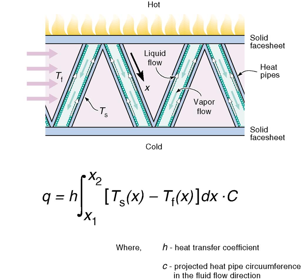
12 A Foam Based Multifunctional Micro Heat-Pipe Concept Solid Face-sheets and Stochastic Cellular Metal Sandwich Panel

13 Operating Range For Heat Pipe Working Fluids
 non-reactive carrier gas (0 20 slm) reactive carrier gas (O 2, N 2, etc.")
14 Electron Beam - Directed Vapor Deposition Electron beam gun beam accelerating voltage = 70 kv maximum power = 10 kw high speed scanning ~ 100 khz spot size < 0.5 mm Multi-pump vacuum system high to low vacuum ( mbar) non-reactive carrier gas (0 20 slm) reactive carrier gas (O 2, N 2, etc.) Hollow cathode plasma high density plasma of gas and vapor stream Integrated substrate biasing constant or alternating, positive then negative, bias (0 ±300 V)
15 Binary Scattering of Atomic Vapor in a Rarefied Gas Flow Mean collision frequency, = nd 2 c r d = molecular diameter (m) n = number density of background atoms(#/m 3 ) c r = relative velocity (m/s) Mean free path, Collision rate, N = c/ N = ½ n c = thermal speed (m/s) For He, ~ Torr Vapor condenses by binary scattering from streamlines that carry flow around the vapor. The local coating thickness depends on the number density of the atoms (I.e. local pressure) and the flow velocity.

16 Coating Open Cell Reticulated Ligaments (Directed Vapor Deposition) Metal/Alloy Deposition Non Line-of-Sight Coatings High Deposition Rates Al, Cu, Ni, Stainless Steel, Promoted by low vacuum environment Up to 100 µm/min many other alloys


17 Electron Beam Directed Vapor Deposition Plasma-assisted DVD combines four process technology components high voltage electron beam evaporation low-vacuum, flowing-gas vapor transport high-density gas and vapor plasma activation pulsed or constant substrate biasing
 by heating at 1 C/min to 250 C,")

18 EB-DVD on Open Cell Reticulated Templates Step 1: Metal Deposition Step 2: Thermal Decomposition of Polyurethane Foam thermally decompose the foam in vacuum (~10-5 Torr) by heating at 1 C/min to 250 C, and holding for two hours results in complete removal of the polymer core with minimal carbon residue Deposition Process Variables: electron beam power carrier gas flow chamber pressure pressure ratio, P u /P c

19 DSMC Simulations: Carrier gas (helium) speed axial direction Chamber Pressure, 0.03 Torr 0.06 Torr 0.13 Torr 0.27 Torr 0.54 Torr carrier gas speed increases with chamber pressure

20 DSMC Simulations: Vapor Distribution Chamber Pressure, 0.03 Torr 0.06 Torr 0.13 Torr 0.27 Torr 0.54 Torr Vapor focusing increases with chamber pressure

21 Gas Jet Flow Effects P c = torr, P u /P c = 5.71 P c = torr, P u /P c = 5.00 P c = torr, P u /P c = 4.79 P c = torr, P u /P c = 4.67 P c = torr, P u /P c = 4.50 P c = torr, P u /P c = 4.23 Polyurethane foam template, cell size = 20 pores per inch (ppi)


22 Copper Deposition: P c = 0.1 Torr, P u /P c = 4.6, 7.5 slm (He) 2.80 kw T f = 138 C 3.50 kw T f = 194 C 4.20 kw T f = 233 C 4.90 kw T f = 279 C planar glass substrate, deposition time = 10 min


23 Copper Deposition: beam power = 4.2 kw P c = torr, P u /P c = 5.71 P c = torr, P u /P c = 5.00 P c = torr, P u /P c = slm 5.0 slm 7.5 slm P c = torr, P u /P c = 4.67 P c = torr, P u /P c = 4.50 P c = torr, P u /P c = slm 12.5 slm 15.0 slm planar glass substrate, deposition time = 10 min


24 Plasma Activated EB-DVD Deposition of Copper beam power = 4.2 kw, 7.5 slm Argon carrier gas Deposition Conditions: Backside no plasma Deposition Conditions: plasma activated (DC + 9V preheat to ~500 C, DC - 75V during deposition)


25 Synthesis of Open Cell, Reticulated Copper Foams Deposition Conditions: electron beam power 4.2 kw He gas flow 7.5 slm chamber pressure 0.14 torr nozzle pressure 0.67 torr pressure ratio 4.8 Template: open cell, reticulated polyurethane foam nominal pore size 20 pores per inch two- sided deposition (no rotation)


26 One Sided Deposition of Copper (front surface) Polyurethane Foam: 20 pores per inch, 15 mm thick

27 Uniform Coating - Copper Foam Ligaments Polyurethane Foam: 20 pores per inch, 15 mm thick

28 Optimized Multifunctional Truss Structures?
29 Periodic Cellular Metal Heat Exchangers
30 Metal Textile Can Be Made In Many Forms REFERENCE: K. Fukuta, R. Onooka, E. Aoki and Y. Nagatsuka in S. Kawabata (Ed.), 15th Text. Res. Symp., The Textile Machinery Society of Japan, Osaka, 1984, pp F.K. Ko, Three Dimensional Fabrics for Composites, In Textile Structural Composites, edited by T.-W. Chou and F.K. Ko, pp , Elsevier, 1989.
 E/E s 0.5 / s c / ys 0.")
31 Lamination Construction a) 2D woven metal structure b) Woven metal micro-truss laminate Easy Flow Stiff / s d/4(w+d) E/E s 0.5 / s c / ys 0.5 / s
 0.635 1.91 0.20 100 (mesh/in) 0.114 0.140 0.35 Insect screening 0.229 1.18 0.13 High Transparency 0.0305 0.")
32 Low Density Laminates Plain Square Woven Metal Cloth Designation d (mm) w (mm) Relative density 1 (mesh/in) (mesh/in) (mesh/in) Insect screening High Transparency

33 Bonding Method Micro-truss laminate core construction Sandwich panel construction
 Easy Fluid")
 Side view Load 10")
34 Multifunctional Micro-Truss Laminate (nichrome) Easy Fluid Flow Excellent Load Support a) Front view b) Side view Load 10 mm Gap 1 mm


35 Materials Diversification a) 110 copper (braze: Ni-25Cr-10P) 10 mm b) 304 stainless steel (braze: Ni-25Cr-10P) 10 mm

36 Actively Cooled Vehicle Skin Structures Possible solution: Open Cell Metal Core Sandwich Panel Wingskins
 Flat sandwich panel Corrugated metal textile core relative density: 0.04 Facesheet thickness: 0.")
37 Sandwich Panel Structure Skin Structurally efficient sandwich construction: two stiff, strong skins with a lightweight core, with a relative density in 3% range (to optimize mechanical response). a) Flat sandwich panel Corrugated metal textile core relative density: 0.04 Facesheet thickness: 0.61 mm 10 mm b) Curved sandwich panel 10 mm Advantages: High fluid permeability, complex shapes, many materials choices, utilize relatively inexpensive materials, (aluminum, titanium, nickel alloys). Low cost manufacturing.
38 THERMAL PROTECTION COATINGS
39 Pore Morphology Control for Low K Materials
.")
40 Conventional Thermal Barrier Coatings Pore volume fraction and morphology strongly effects both the thermal conductivity and thermomechanical performance of the TBC layer The deposition process establishes the initial pore fraction and morphology Sintering during service evolves the pore volume fraction, and morphology (and the thermal and thermo-mechanical properties). We are exploring concepts to manipulate porosity during deposition. Concepts extendable to other materials (lower thermal conductivity and sinter rates.

41 Porosity Can Be Manipulated Via Flux Shadowing Mechanisms Flux angular distribution width = 120, distribution peak = 0 Increasing adatom surface mobility reduces flux shadowing by allowing an adatom to move to a shadowed region on the substrate Broadening the incidence angular distribution enhances the significance of shadowing and increases pore fraction.

42 Pore Distribution in Vapor Deposited Coatings (Thermally Limit Surface Transport, Exploit Shadowing) Substrate rotation is used in EB-PVD to broaden the effective incidence angle distribution and create thermo-mechanically beneficial intercolumnar pores.
 enables the incidence angle distribution to be")
43 EB-DVD I Concept Gas phase scattering of vapor (by collisions with background gas) enables the incidence angle distribution to be broadened

44 EB-DVD Process Environment E-beam Nozzle Vapor Flux Heater Crucible Substrate

45 EB-DVD Versus EB-PVD

46 Coating Characterization Type I Pore Parameters
47 Coating Properties Constant Upstream Pressure (P u =2Torr) Total pore volume fraction greatly increase with chamber pressure High evaporation rates and low pressure ratios also promoted a high pore volume
48 Morphology at Constant Upstream Pressure Type I Pore Spacing Type I Pore Width Type I pore spacing and width increase with chamber pressure

49 Thermal Conductivity (Constant Upstream Pressure) Rate = 5.0 m/min. Flow = 8.0 slm He Temp. = 1000 o C = 1.9 W/mK = 5.3 g/cm 3 = 1.3 W/mK = 3.9 g/cm 3

50 kmc Simulations Asperity Height Large asperities promote Type I pore formation

51 Pore Morphologies

52 Zig Zag TBC Coating Concept Pore morphology optimized for low thermal conductivity and high thermomechanical resistance

53 TBC Microstructure

54 Thermal Conductivity Measurements *Type I pore nucleation control
55 Summary Emerging manufacturing concepts (rapid prototyping), directed vapor deposition and 3D weaving are creating new opportunities for meso structure control. These manufacturing approaches facilitate novel thermal engineering concepts: -Microheat pipe structures for 3D heat exchangers -Low backpressure multifunctional heat exchangers -Ultralow conductivity thermal protection systems that utilize pore morphology control