ME 333 Manufacturing Processes II
|
|
|
- Fay Harper
- 5 years ago
- Views:
Transcription

1 ME 333 Manufacturing Processes II Chapter 5 Metal Working Processes Mechanical Engineering University of Gaziantep Dr. A. Tolga Bozdana
2 Introduction Metal forming involves large group of manufacturing processes in which plastic deformation is used to change the shape of metal parts. Deformation results from the use of a tool (a die) that applies stresses exceeding the yield strength of metal. Thus, the metals deforms to take a shape defined by the geometry of die. To be successfully formed, the metal must have certain properties. Desirable properties for forming are low yield strength and high ductility, which are affected by temperature. Ductility is increased and yield strength is reduced when the work temperature is raised. Usually compressive stresses are applied to plastically deform the metal. Depending upon purpose, forming processes are used to stretch, bend, orshear the metal. Plastic Deformation Processes: Operations that induce shape change on the workpiece by plastic deformation under forces applied by various tools and dies. Bulk Deformation Processes: Operations with large amount of plastic deformation. Cross-sectional change without volume change. Ratio of cross-section area to volume is small. Mostly hot or warm working conditions are preferred although some operations are carried out at room temperature. Sheet Forming (Sheet Metal Working) Processes: No cross-sectional change, but only shape change. Ratio of cross-section area to volume is high. Always performed as cold working operations, they are performed on thin (lessthan6mm) sheets, strips or coils of metal by means of a set of tools (punch & die) on machine tools (stamping presses). 1

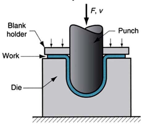
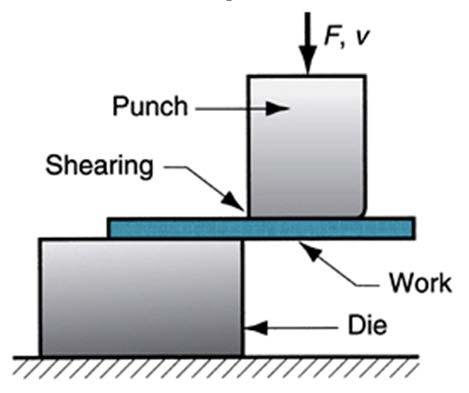
3 Metal Forming Bulk Deformation Sheet Metal Working Rolling Forging Extrusion Drawing (Wire, Bar) Bending Drawing (Deep, Cup) Shearing 2
4 Material Considerations In plastic region, material behaviour is defined by flow curve (as shown in figure). f Flow stress (the instantaneous stress required to continue deformation) can be obtained as follows (K and n are given in material property tables or calculated from material testing curves): f K n f : flow stress K : strength coefficient n : strain hardening coefficient Sometimes, analysis is based on average (mean) stress over strain-stress curve from beginning of strain to the final (max.) value during deformation: K n 0 : average (mean) flow stress f 0 f : max. strain during deformation 1 n 0 y flow curve n K f Strain or work hardening (cold working): It refers to strengthening of metals by plastic deformation due to dislocation movements within the crystal structure. It is a significant material characteristic defining both material properties and process power, and it can be removed by annealing. 3
5 Temperature in Metal Forming Flow curve is valid for an ambient (room) temperature. For any material, K and n depend on the temperature. Thus, material properties change with the work temperature. Thus, metal forming processes can also be classified according to working temperature of the metal: (T a : ambient temperature, T m : melting temperature) cold working warm working hot working log σ K n increase in work temperature T a 0.3 T m 0.5 T m 0.75 T m T m log ε The effect of temperature gives rise to distinctions between cold working, warm working, and hot working. Hot and cold working of metals is of great importance in engineering production. Certain processes (e.g. forging, rolling, drawing, and extrusion) predominate in the primary stages of production, and they have been perfected through developments. 4
6 Temperature in Metal Forming Cold Working It is performed at room temperature (or below the recrystallization temperature of metal). better accuracy and surface finish, increase in strength and hardness, no heating required. high forces and power required, decrease in ductility of metal, limitations on amount of forming, additional annealing required for some materials, not suitable for some materials. Warm Working Performed at between room temperature and the recrystallization temperature. lower forces and power required, more complex part shapes, no annealing required. some investment in furnaces is needed. Hot Working Being performed at above the recrystallization temperature, it is the initial step in mechanical working of most metals and alloys. high amount of forming possible, lower forces and power required, forming of materials with low ductility, no work hardening (so no additional annealing) required. surface oxidation and decarburisation due to high temperatures, lower accuracy and surface finish, higher production costs, shorter tool life. 5
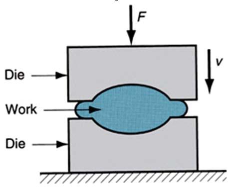
. F A V h 0 0 Under ideal conditions (i.e. in absence of friction between platens and part), any height reduction causes uniform increase in area (from A o to A f ).")
7 Friction Effect Homogeneous Deformation If a solid cylindrical part is placed between two flat platens and the load (F) is increased until reaching the flow stress (σ o ) of material, then its height will be reduced (from h o to h f ). F A V h 0 0 Under ideal conditions (i.e. in absence of friction between platens and part), any height reduction causes uniform increase in area (from A o to A f ). Inhomogeneous Deformation However, in practice, friction between platens and part cannot be avoided. F V 0 1 h D 3h The change in part geometry is not uniform, and the final part takes a barrel shape. The load required can be estimated based on friction coefficient (µ). 6


8 Forging Forging is the working of metal into a useful shape by hammering or pressing. It is the oldest metal working process. Most forging operations are carried out hot although certain metals may be cold forged. Two broad categories of forging processes are open-die forging and closed-die forging. Closed-die forging uses carefully machined matching die blocks to produce forging to close dimensional tolerances. According to the degree to which flow of the metal is constrained by the dies, there are three types of forging processes: open-die, impression-die, and flashless open-die forging impression-die forging flashless forging 7


9 Open-Die Forging Known as upsetting, it involves compression of a work between two flat dies or platens. forging of a large turbine shaft (1) forging of a pressure vessel cylinder (2) (3) 8

.")


10 Impression-Die Forging In impression-die forging, some of the material flows radially outward to form a flash (çapak). (1) (2) (3) Hot impression-die forging of a crankshaft (bottom to top) Impression-die forging of a connection rod (top to bottom) 9

.")


 (2) (3) Closed-die forging")
11 Flashless (Precision) Forging Work material is entirely surrounded by die cavity during compression (i.e. no flash is formed). In this operation, the most important requirement is that the work volume must equal the space in die cavity to a very close tolerance. (1) (2) (3) Closed-die forging with flash Flashless (precision) forging 10


12 Coining This is a special application of flashless forging in which fine detail in the die are impressed into top and bottom surfaces of the workpiece. There is a little flow of metal in this process. (1) (2) (3) 11

 m : mass of the ram ( kg) g h : drop")
13 Forging (Drop) Hammers (Şahmerdan) Force is aplied by means of a falling weight. They are energy-restricted machines since deformation results from dissipating kinetic energy of the ram. Their capacity is expressed with energy units. Forging Equipment PE Wh mgh PE : potential energy ( Nm) m : mass of the ram ( kg) g h : drop height ( m) 2 : gravitational acceleration ( m / s ) 12

14 Hydraulic Presses They are load-restricted machines due to pressure in oil. Their capacity is expressed with load. Forging Equipment 13


15 Forging Equipment Mechanical Presses They are stroke-restricted machines as the length of stroke and available load at positions of stroke represent their capacity. Their capacity is expressed with load. Crank Press Knuckle-Joint Press Eccentric Press Screw Press Rack & Pinion Press 14
16 Forging Load For simplicity in determination of the forging load for free upsetting (open-die forging), two assumptions can be made: 1. Material is perfectly plastic (i.e. the flow stress remains constant). 2. No friction between part and die surfaces (i.e. radial flow of material is uniform throughout height). Thus, true strain is: ε =ln(h 0 /h f ) 0 Volume A h Ah 0 0 A V h Load (P) P A & P A P 0 V h 0 h 0 W Pdh 0V ln h 0V f h f h P Work (W) h 0 Stroke h f 15
17 Forging Load If the friction is taken into account in open-die forging, then Schey Equation is used: V P 0 1 D h 3h For closed-die forging, the forging load is estimated by: P c A A T 0 T : total cross-section area c = (for open-die forging) In such case, the work done can be calculated proportionally: P P W W without friction with friction c c = (for simple shape closed-die forging) = (for complex shape closed-die forging) 16
18 Rolling It is a metal deformation process where thickness of a metal plate is reduced by successive passes from rolls: t0 tf A0 Af Reduction ratio ( r) : 100 or 100 t A 0 0 Work (metal plate) exits from rolls at a higher speed than it enters: V V f 0 The grains are elongated after cold rolling, and grain size is reduced after hot rolling. A 0 V r P Cold Rolling (elongated grains) Hot Rolling (fine grains after recrystallization) Af A A t t 0 f 0 f : cross-sectional area before rolling : cross-sectional area after rolling : plate thickness before rolling : plate thickness after rolling t 0 t f P : rolling load V 0 V r P V f V V V 0 f r : speed of work at entering into rolls : speed of work at exiting from rolls : rotational speed of rolls 17
19 Rolling Various configurations of rolling mills are available in cold rolling and hot rolling: HOT ROLLING COLD ROLLING Two-high mill Three-high mill Four-high mill Cluster mill (for stronger metals) Planetary roll (for high reduction) 18
20 Steel Rolling First, steel is cast into ingots and stored in such shape. Soaked ingots (preheated at 1200 C) are then rolled into intermediate shapes: blooms, slabs, orbillets. A bloom (rolled from ingot) has a square section of larger than 150x150 mm. A billet (rolled from bloom) has a square section of 40x40 mm up to size of bloom. Aslab(rolled from ingot or bloom) has a rectangular section with min. width of 250 mm and min. thickness of 40 mm. Finally, these intermediate shapes are rolled into different products as illustrated in figure. 19
.")

21 Steel Rolling Other versions of steel rolling are as follows: Shape rolling: The work is deformed by gradual reduction into a contoured cross section (such as I-beams, L-beams, U-channels, rails, round, squire bars and rods, etc.). Ring rolling: Thick-walled ring of small dia. is rolled into a thin-walled ring of larger dia. Thread rolling: Threads are formed on cylindrical parts by rolling between two thread dies. Gear rolling: Similar to thread rolling with three gear rolls forming gear profile on the work. Gear Rolling Ring Rolling Thread Rolling 20
22 Mechanics of Rolling Roling takes place throughout the arc of contact, V V V 0 r f which is defined by angle of contact (angle of bite). V f Roll velocity At neutral (no-slip) point, speed of work is equal to V r speed of rolls. Before/after this point, slipping/friction V 0 Work velocity occur between rolls and work. Plane-strain conditions are valid (i.e. assuming no Neutral (no-slip) Point L change in width of work). Thus, volume rate of work metal is constant at any point throughout rolling: bt V btv bt V 0 0 f f N : neutral (no-slip) point : contact (bite) angle t 0 V 0 V r R α N V f t f R : radius of rolls L L : length of arc contact V r b : width of work 21
23 Limiting Conditions for Rolling Friction force (F) depends on the coefficient of friction (µ) between rolls and work: F P r At arbitrary point (A), horizontal components of rolling force (P r ) and friction force (F) are related: Fcos P r sin t 0 V 0 V r V r F P r sin tan cos The amount of slip (s) can also be measured by means of forward slip: Draft (d) is sometimes used as reduction ratio: 0 f In practice, max. draft (d max ) is: 0 no draft ( no rolling) Cold Rolling Warm Rolling dmax Hot Rolling µ 0.1 µ 0.2 µ R d t t P r A R F L α N s V V V f r r V f tan t f 22
24 Rolling Force The following parameters should be considered in rolling force calculations: Roll diameter (affects rolling force and contact length) Flow strength of work material (affected by strain rate and temperature) Friction between rolls and work (varies in cold, warm, or hot rolling) Presence of front and/or back tension (related with work material behaviour) Rolling load (P) based on plane strain condition with friction: Q 2 1 Q 0 1 p P e bl 3 Q L p t Lp R t0 tf Rt t 0 V 0 V r P r R A F α N V f t f 0 L p t t : mean flow stress : projected arc length : mean thickness : reduction in thickness V r L L p 23
25 The rolling force calculations can be simplified as follows: Rolling Force (Simplified Calculation) Rolling force: F bl Length of contact: L R 0 : angle of contact ( rad) Torque: T F 2 L Arc length (L) and projected length (L p ) are close: L L p Power (on each roll): P T 0.5FL Power (on two rolls): P 2 0.5FL FL t 0 V 0 V r P r R A F α N V f t f : rotational speed of roll ( rpm) L V r L p 24
26 Example: A strip (300x25 mm) is fed through rolling mill with two powered rolls (each of 250 mm radius). The work thickness is to be reduced to 22 mm (in one pass) at a roll speed of 50 rpm. Theflow stress of work material is 180 MPa, and the coefficient of friction between roll and work is Determine whether the friction is sufficient to permit rolling operation to be accomplished. If so, calculate roll force, torque and horsepower. Solution: Determine angle of contact (α): R R t0 t f cos 2 For limiting rolling conditions: tan d d max 250 cos tan d mm 2 d R mm 2 max α Rcosα feasible feasible
27 Solution (Cont d): Calculate arc length of contact (L): L R 250 mm 6.28 rad27.4 mm 180 N mm 6 F 0 bl mm 27.4 mm N 2 Calculate rolling force (F): Calculate torque (T): 6 1 m 3 T 0.5FL N 27.4 mm Nm 3 10 mm Calculate power (P): 6 1 m rev 1 min 2 rad P FL N27.4 mm kw 3 10 mm min 60 s 1 rev Power in hp: 1 kw hp kw P hp


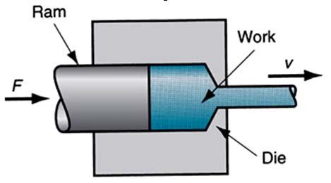
28 Extrusion It is a process in which the work is forced to flow through a die opening to produce a desired cross-sectional shape. In other words, a block of metal is reduced in cross-section by forging it to flow through a die under pressure. It can be used to produce cylindrical bars or hollow tubes, aswellasirregular cross-sections. Lead, tin, aluminum alloys can be cold extruded. Horizontal type presses are used. Speed of extrusion depends on temperature and type of material used. 27


 Extrusion Principle The work is")

29 Types of Extrusion Extrusion is performed in different ways, and hence different classifications are available: direct or indirect; hot or cold; continuous or discrete Process Direct (Forward) Extrusion Indirect (Backward) Extrusion Principle The work is forced to flow through a die opening. The work flows in the reverse direction of ram. Solid Parts Hollow Parts 28
30 Extrusion Force and Energy Figure shows a typical plot of ram pressure vs ram stroke (and the remaining billet length). The higher values in direct extrusion result from friction at the container wall. Shape of initial pressure build-up depends on die angle (higher the angle, steeper the build-up). The increase in pressure at the end of stroke is related to butt formation (a small portion of billet that cannot be forced through die opening). Ram force (F) and ram power (W) can be calculated in a similar way of forging: F A 0 0A0ln A f W hf 0V ln h0 F D 0 D f h 0 h f 29

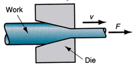
31 Drawing (Rod, Bar, Wire) It involves pulling the metal through a die by means of a tensile force applied to the exit side. The end is grasped by tongs on a draw bench and pulled through. There may be few successive drawing dies on continuous drawing. Drawing load can be obtained as (assuming that thereisnofriction): : die angle (half angle) L c : contact length Die F A 0 0Af ln A f Drum F back Die F front Drum The number of dies varies from 4 to12, and the maximum possible reduction per pass is In practice, draw reductions per pass are well below the theoretical limit. Reductions of 0.5 for single-draft bar drawing and 0.3 for multiple-draft wire drawing seem to be the upper limits. 30