Gas Tungsten Arc Welding (GTAW) Tungsten Inert Gas (TIG) Welding / 141
|
|
|
- Tyrone Owens
- 5 years ago
- Views:
Transcription

1 Gas Tungsten Arc Welding (GTAW) Tungsten Inert Gas (TIG) Welding / 141 Professor Pedro Vilaça * * Contacts Address: P.O. Box 14200, FI Aalto, Finland Visiting address: Puumiehenkuja 3, Espoo pedro.vilaca@aalto.fi ; Skype: fsweldone * ISO 4063:2009 -Welding and allied processes - Nomenclature of processes and reference numbers. (Establishes a nomenclature for welding and allied processes, with each process identified by a reference number) January 2015 Contents Process fundaments Welding parameters (the electrode as the heart of the process) Equipments and accessories Advantages and limitations Typical industrial applications Technological variants 2 1


2 Learning Outcomes At the end of the lecture the student should be able to: 1. To define the physical fundaments of the GTAW process 2. To establish the welding parameters 3. To identify and classify the type of equipment and components 4. To select the chemical and geometrical condition for electrodes 5. To identify the variants and their governing features 6. To establish the advantages and limitations 7. To establish typical industrial applications 3 Fundaments GTAW/TIG/141 Process Fusion welding process using the electric arc as heat power source Electric arc is established between a non consumable thermo-ionic electrode (tungsten, W, with eventual addition of other components) and the workpieces 4 2


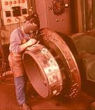
3 Fundaments GTAW/TIG/141 Process Apparatus 5 Fundaments GTAW/TIG/141 Process Apparatus 6 3
, helium (He) or")

4 Fundaments GTAW/TIG/141 Process Apparatus 7 Fundaments GTAW/TIG/141 Process The plasma is established in inert gas atmosphere, namely: argon (Ar), helium (He) or mixtures of both (Ar + He) It is not possible to use as shielding gas any kind of active gases due to need of preserve/protect the thermo-ionic electrode during arc discharge 8 4
 or if filler metal is needed it can be added as an outer rod introduced into the weld pool, produced by")

 is also used with great advantages in weld quality, due too less HI,")
5 Fundaments GTAW/TIG/141 Process The inert gas is used as shielding gas of the weld pool and weld seam during solidification Weld seam can be obtained autogenously (without any filler metal added) or if filler metal is needed it can be added as an outer rod introduced into the weld pool, produced by the electric arc Although one of the first fusion welding process, is still considered the best conventional electric arc welding process, in terms of arc control and stability, and weld bead final quality 9 Fundaments GTAW/TIG/141 Process Current and Polarirty Uses DCEN for most of the applications and AC current for weld materials with refractory superficial layers, e.g. aluminium alloys Pulse current (typically under DCEN, but also possible with AC) is also used with great advantages in weld quality, due too less HI, and higher productivities (concerning weld speed and penetration/width ratio) DCEN DCEP 10 5
 module at the power source, enabling no contact between electrode and the workpieces")

.")

6 Fundaments DCEN versus DCEP 11 Fundaments Arc Start Arc start is typically performed with High Frequency (HF) module at the power source, enabling no contact between electrode and the workpieces Short circuit and lift arc techniques are possible alternative as arc start techniques but not desirable Short circuit or lift arc start techniques are possible, but not desirable due to eventual contamination of the workpieces/weld seam with electrode particles (will result in a defect: inclusion). A sacrificial plate can be used to avoid inclusions, with short circuit or lift arc start techniques Even with a sacrificial plate, if short circuit or lift arc are used as arc start techniques, then for sure electrode will be contaminated and is future performance and durability is definitely compromised 12 6


 Enables always sharp and clean")
7 Fundaments Arc Start by Short Circuit and Lift Arc Procedures Copper as sacrificial plate is a good option 13 Fundaments Arc Start by High Frequency Module In DCEN ON start In AC Always sinusoidal wave power sources Low current with high voltage (tens of kvolts) Enables always sharp and clean electrode tip: 14 7
 End sequence procedure: Stops current flow (down-slope) Close")
8 Start sequence procedure: Fundaments GTAW Procedure Sequence Open gas flow (pre-flow) Start arc by HF start current flow During open arc: Push - to maximum filler metal into weld pool Filler is introduced into weld pool not in the arc, to avoid contamination of the electrode Pull - to maximum penetration (with no filler metal) End sequence procedure: Stops current flow (down-slope) Close gas flow (post-flow) 15 Fundaments GTAW Procedure Sequence 16 8


9 Fundaments Procedure Sequence Tack welds 17 Fundaments Procedure Sequence Start and End of the Welds Electrode should be heated prior arc start sequence Slope up current at start Slope down current at end (if possible) start and end in sacrificial plates/zones of the workpieces 18 9


10 Fundaments Procedure Sequence Backing (with Shielding Gas) 19 Fundaments Procedure Sequence Backing (other solutions) 20 10


11 Fundaments Procedure Sequence Cleaning Workpieces + Electrode Mechanical cleaning Chemical cleaning Humidity removal Focusing aluminium and titanium alloys 21 Parameters Key Variables Current Filler Metal AC or DCEN or Pulse Electrode Voltage Diameter Travel Speed Composition Shielding gas Pre heat time Composition and flow Stick-out extension Preflow and postflow time Tip geometry Inner diameter of ceramic nozzle 22 11

: Plain steel; HSLA;")

: Because of")
 May result in")
12 AC: Parameters Current: AC versusdc Aluminium; aluminium alloys; Magnesium; magnesium alloys DC (remaining weldable engineering alloys): Plain steel; HSLA; stainless steel; etc Copper; copper alloys Titanium Niobium, etc 23 Parameters Current: Why AC in Aluminium? Aluminium core (T f =600ºC): Because of refractory superficial layer Al 2 O 3 (T f =2100ºC) May result in burn-through defects 24 12


13 DCEN AC DCEP Parameters Current: Why AC in Aluminium? DCEN period: Workpieces heated to fusion; No electrode contamination DCEP period: Cleaning effect of refractory superficial layer Electrode contamination 25 Parameters Current: AC 26 13

14 Parameters Current: AC Balancing 27 Parameters Current: Pulsed Varying the current from a high peak amperage level to a lower background amperage level at regular intervals Pulse controls also adjust for the number of pulse per second and the percent of time spent at the peak amperage level Pulsing is used to control heat input and allow for improved weld profile 28 14
15 Parameters Current: Pulsed Pulse : Theory I m I p t t p p I t b b t b Real 29 Parameters Current: Pulsed I m I p t t p p I t b b t b V I HI v m I m I convencional E c _ pulsado E c _ convencional 30 15

16 Parameters Shielding Gas: Argon Argon is obtained as a byproduct in the manufacturing of oxygen. provides excellent arc stability and cleaning action. Has low thermal conductivity which means it is not a good conductor of heat. Thus the arc density is high (refers to the concentration of energy in the arc) 31 Parameters Shielding Gas: Type and Influence of Composition 32 16
17 Parameters Shielding Gas: An Exception in the Composition Exceptionally, shielding gas can combine argon (Ar) with 5 to 15% of Hydrogen (H 2 ) for welding some particular non-ferrous, e.g.: nickel, copper, titanium. This procedure envisage the high thermal conductivity of dissociated hydrogen 33 Parameters Shielding Gas: Flow Gage Correct flow rate is an adequate amount to shield the molten weld pool and protect the tungsten electrode: Typical values range in 8 to 14 l/min Influence by: welding current, nozzle diameter, electrode and position Corner or edge joints, excessive flow rates can cause air entrapment, effectiveness is improved by reducing the gas flow by about 25% 34 17


18 Parameters Shielding Gas: Flow versus Weld Joint and Position 35 Parameters Shielding Gas: Inner Diameter of Ceramic Nozzle Nozzle internal diam. = 4 X electrode diam. Nº nozzle reference to internal diameter, e.g. Nº5=5x1/16 =7.9 mm 36 18


19 Parameters Shielding Gas: Preflow and Postflow To prevent contamination of both the weld pool and the tungsten electrode by the surrounding atmosphere Preflow will clear the air and moisture from the torch and prevent this contamination (time depends of working volume) Postflow prevent oxidization from occurring by shielding the hot electrode and weld area and by speeding up the cooling process (1 second/10 amps) If tungsten that has discolored because of oxidization must be properly removed 37 Parameters Shielding Gas: Purge at the Root of the Weld 38 19

20 Parameters Electrode: Size 39 Parameters Electrode: Composition 40 20

21 Parameters Electrode: Composition 41 Parameters Electrode: Composition Tungsten Electrode: Thermionic emission with T f =3000ºC Increases emissivity and thus life with adition of Th, Zr, Ce, La. Although some reduction of the fusion temperature 42 21
22 Parameters Electrode: Composition EWTh Electrode Classification: In these electrodes, the thermionic emission of tungsten can be improved by alloying the tungsten with metal oxides that have very low work functions. As a result, these electrodes can be used with higher welding currents. Thorium oxide (ThO2), called thoria, is one such additive Two types of thoriated tungsten electrodes are available. EWTh-1 and EWTh-2 electrodes contain 1% and 2% thoria, respectively, evenly dispersed through the entire length of the electrodes When compared to pure tungsten (EWP) electrodes, thoriated tungsten electrodes provide a 20% higher current-carrying capacity, generally have a longer life, and provide greater resistance to contamination of the weld. Arc starting is easier and the arc is more stable than with pure tungsten or zirconiated tungsten electrodes The EWTh-1 and EWTh-2 electrodes were designed for DCEN applications because they maintain a sharpened tip configuration during welding, the desired geometry for DCEN welding operations 43 Parameters Electrode: Composition EWCe Electrode Classification: First introduced into the U.S. market in the early 1980s, these electrodes were developed as possible replacements for thoriated electrodes because cerium is not a radioactive element. The EWCe-2 electrodes contain 2% cerium oxide (CeO2), referred to as ceria Compared with pure tungsten, the ceriated electrodes facilitate arc starting, improve arc stability, and reduce the rate of vaporization or burn-off The advantages of ceriated electrodes improve in proportion to increased ceria content. EWCe-2 electrodes operate successfully with AC or DC of either polarity 44 22
23 Parameters Electrode: Composition EWLa Electrode Classification: Electrodes with lanthanum oxide additions were developed at about the same time as the ceriated electrodes and for the same reason lanthanum is not radioactive. The advantages and operating characteristics are similar to those of the EWCe-2 electrodes Three types are available: EWLa-1, EWLa-1.5, and EWLa-2 The EWLa-1 electrodes contain 1% lanthanum oxide (La2O3), referred to as lanthana. The advantages and operating characteristics of these electrodes are very similar to the ceriated tungsten electrodes. EWLa-1.5 electrodes contain 1.5% of dispersed lanthanum oxide, which enhances arc starting and stability, reduces the tip erosion rate, and extends the operating current range EWLa-2 electrodes contain 2% dispersed lanthanum oxide; this is the highest volume of oxide of any of the specific, single-additive, AWS-specified electrode types. The high oxide content enhances arc starting and stability, reduces the tip erosion rate, and extends the operating current range 45 Parameters Electrode: Composition Zirconiated tungsten electrodes (EWZr) contain 0.25% zirconium oxide (ZrO2): They have welding characteristics that generally fall between those of pure tungsten and thoriated tungsten electrodes. With AC welding, EWZr combines desirable arc stability characteristics and aballed end typical of pure tungsten, with the current capacity and starting characteristics of thoriated tungsten. They have higher resistance to contamination than pure tungsten and are preferred for radiographic-quality welding applications where the tungsten contamination of the weld must be minimized 46 23
24 Parameters Electrode: Tip Geometry 47 Parameters Electrode: Tip Geometry 48 24

 49")


25 Parameters Electrode: Hot Start (preheat time) 49 Parameters Electrode: Stick-Out Extension DCEN: l = 2-3 x Diam. Electrode 50 25

26 Depends on metallurgical, physical and chemical compatibility with base materials Properties of the structural application Thickness depends of the type and level of the current and weld position Parameters Filler Metal: Composition 51 Parameters Filler Metal: Standard EN 1668 Identification Code Plain steel / Fine Grain EN 1668 W 46 3 W3Si1 EN 1668 standard W filler metal rod for GTAW 46 Code with mechanical properties of filler metal rod (see table 1) 3 code with the temperature correspondent to 47 J for impact energy (see table 2) W3Si Code with the chemical composition of the filler metal (see table 3) 52 26

27 Parameters Filler Metal: Standard EN Advantages Weld more kinds of metals and metal alloys Stainless steel, nickel alloys, titanium, aluminum, copper, brass Also can weld dissimilar metals to each other. Copper to brass Stainless steel to mild steel. Concentrated Arc Pin point control of heat input to the workpiece. Narrow heat affected zone Low susceptibility of introducing hydrogen in weld pool Weld in all the positions and is Easy to automate No Slag No Sparks, Spatter or Noise No Smoke or Fumes 54 27
28 Limitations Low filler metal (max. length = 1000mm) deposition rate (<= 0,5 Kg/h) Low duty-cycles Limited to about thickness <= 8mm Cost of inert shielding gas Very sensitive to air flow typical from outdoor applications Need hand-eye coordination to accomplish the weld Arc Rays are brighter than normal welding, thus need additional care to protect skin with proper clothes and welding lens Risk of tungsten inclusion in weld seam 55 Applications Thickness versus Beveling Weld in all the position: Tubes, Plates, Profiles Root welds with or without backings Minimum thickness = 0.5mm ; maximum thickness = 8mm (higher thickness became not economically feasible Enables easy automation and robotization Excellent quality in welding all the weldable materials, namely the more reactive metals, e.g.: Al, Cu, Ti, stainless steel, etc Chemical, petrochemical Industries shipbuilding in aluminium industry Pipelines and other shell components, e.g.: pressure reservoir Food industry Medical industry 56 28


29 Applications Thickness versus Beveling 57 Applications Thickness versus Beveling GTAW Manual with Filler Material GTAW Manual without Filler Material SGTAW Automatic 58 29
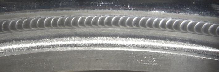


30 Applications Typical Good Superficial Appearance of GTAW Welds 59 Applications 60 30


31 Applications 61 Equipments and Accessories Power Source Ducty-cycle of about 35% (10min at max. current) Constant-current characteristic OCV (Open Circuit Voltage) min = 75V Short circuit current 62 31


32 Equipments and Accessories Torch Collet should be adjust to Electrode diameter 63 Equipments and Accessories Torchs 64 32


33 Equipments and Accessories Shielding Gas Gauge 65 Equipments and Accessories Remote Control 66 33


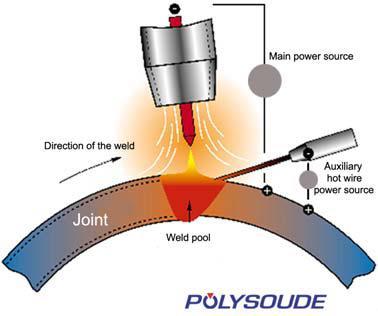

34 Equipments and Accessories Ground Clamps (fixed and rotative) 67 Variants GTAW Hot Wire for Narrow Gap (1/2) 68 34
 Method of increasing the penetration capability of the arc in TIG welding Achieved through the application of a thin coating of activating flux material onto the")
35 Variants GTAW Hot Wire for Narrow Gap (2/2) Note: Inconel is a registered trademark that refers to a family of austenitic nickel-chromium-based superalloys for high temperature applications 69 Variants Activated TIG: A-TIG (1/14) Method of increasing the penetration capability of the arc in TIG welding Achieved through the application of a thin coating of activating flux material onto the work piece surface prior to welding Effect of flux is to constrict the arc which increases the current density at the anode root and the arc force on the weld pool The consistency in quality, reduced need for edge preparation, reduced distortion and the improved productivity could make the A-TIG welding process more attractive than the conventional TIG, e.g., process in tube welding 70 35

")
36 Variants Activated TIG: A-TIG (2/14) Activating fluxes for TIG welding was first reported by the EO Paton Institute of Electric Welding in the former Soviet Union in the 1950s More recently activating fluxes have become commercially available from several sources These fluxes claim to be suitable for the welding of a range of materials, including C-Mn steel, Cr-Mo steels, stainless steels and nickel-based alloys The fluxes are generally available in the form of either an aerosol or as a paste (powdered flux mixed with a suitable solvent) which is applied onto the surface with a brush The activating fluxes can be applied in both manual and mechanised welding, although it is more difficult to control in the former mode of operation 71 Variants Activated TIG: A-TIG (3/14) Electric Arc Comparison (application to Stainless Steel) Conventional TIG A-TIG 72 36
37 Variants Activated TIG: A-TIG (4/14) Advantages A-TIG versus conventional TIG Increased productivity due to greater depth of penetration, i.e., up to 8mm in stainless steel compared to 3mm for conventional TIG welding Increased productivity is derived through a reduction in welding time and/or a reduction in the number of welding passes Reduced distortion, i.e., the use of a square edge closed butt joint preparation reduces weld shrinkage compared with a conventional multipass V butt joint Problems of inconsistent weld penetration associated with cast-to-cast material variations can be eliminated. For example, deep penetration welds can be made in low sulphur stainless steel (~0.002%), which would otherwise show a shallow, wide weld bead in conventional TIG welding (see: 73 Variants Activated TIG: A-TIG (5/14) The actual mechanism by which the application of flux constricting the arc is not fully understood Despite the productivity benefits of A-TIG welding, industry to date has been slow in exploiting this process. Because: The use of the flux is seen as an additional cost and its application an additional operation Commercial fluxes tend to produce an inferior surface finish compared to conventional TIG welding Produce a surface slag residue which is required to be removed 74 37
38 Variants Activated TIG: A-TIG (6/14) Proposed mechanisms of A-TIG welding Ability of flux to wet surface of the molten pool has an effect on composition modifying the surface tension. Change in fluid flow is related Thermal Coefficient of Surface Tension (TCST) of the molten pool: If the TCST is negative, the cooler peripheral regions of pool will have a higher surface tension than the centre of the weld pool and the flow will be outwards creating a wide shallow weld pool In materials with a positive gradient, this flow is reversed to the centre of the weld pool and in the centre the molten material flows down. This creates a narrower deeper weld pool for exactly the same welding conditions 75 Variants Activated TIG: A-TIG (7/14) Proposed mechanisms of A-TIG welding Change in fluid flow is related Thermal Coefficient of Surface Tension (TCST) of the molten pool: TCST is positive TCST is negative 76 38

39 Variants Activated TIG: A-TIG (8/14) Proposed mechanisms of A-TIG welding Spectroscopic analysis shows a decrease in intensity of argon lines and an increase in intensity of alkali metals in the arc medium Arc constriction effect of flux is related to the evaporation of the flux and its preferential ionisation Preferential ionisation of the alkali metals and its high dissociation temperature are believed to be responsible for the arc constriction Strong electromagnetic force from the constructed arc is believed to reverse the flow pattern overcoming the effect of TCST in A-TIG 77 Variants Activated TIG: A-TIG (9/14) Proposed mechanisms of A-TIG welding 78 39


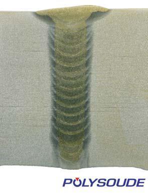
40 Variants Activated TIG: A-TIG (10/14) Transverse weld section of A-TIG and conventional TIG welds in 48mm OD, 4mmWT 304L stainless tube 79 Variants Activated TIG: A-TIG (11/14) Transverse weld sections of Conventional TIG and A-TIG welds in 29mm OD 1.6mm WT laser seam weld 304L tube 80 40


41 Variants Activated TIG: A-TIG (12/14) Transverse weld sections of A-TIG and conventional TIG welds in 6mm OD, 1.0 WT 304 L stainless tubes 81 Variants Activated TIG: A-TIG (13/14) Conventional TIG and A-TIG welds in 29mm OD 1.6mm WT laser seam welded 304L tube showing a deflected weld bead in the conventional TIG 82 41
 Activating flux - increasing the performance and productivity of the TIG and plasma processes, Welding and Metal")
42 Variants Activated TIG: A-TIG (14/14) Photomicrographs of transverse macro sections of weld on 316L grade steel produced at 180A welding current and 85mm/min welding speed with A-TIG and conventional TIG welding 83 Literature supporting the A-TIG References Lucas W, Howse DS (1996) Activating flux - increasing the performance and productivity of the TIG and plasma processes, Welding and Metal Fabrication Gurevich SM et al. (1965) Improving the penetration of titanium alloys when they are welded by argon tungsten arc process' Automatic Welding Makara AM et al. (1968) High-tensile martensitic steels welded by argon tungsten arc process using flux' Automatic Welding Voropai NM and Lebedeva (1989)Physical properties of welding fluxes based on TiO, formed in melting activated wires' Automatic Welding 84 42
43 Literature supporting the A-TIG References Heiple CR and Roper JR (1982) Mechanism for minor element effect on GTA fusion zone geometry' Welding Journal Simonik AG (1976) The effect of contraction of the arc discharge upon the introduction of electro-negative elements Welding Production Ostrovskii OE et al. (1997) The effect of activating fluxes on the penetration capability of the welding arc and the energy concentration in the anode spot' Welding Production V Kumar, et al. (2009) Investigation of the A-TIG mechanism and the productivity benefits in TIG welding. JOM 15 and 6th International Conference on Education in Welding (ICEW 6) 85 43