Fatigue Testing and Life Estimates of Welded Flat Head Pressure Vessel Joints. Chris Hinnant Paulin Research Group Houston, TX
|
|
|
- Cameron James
- 5 years ago
- Views:
Transcription
1 Fatigue Testing and Life Estimates of Welded Flat Head Pressure Vessel Joints Chris Hinnant Paulin Research Group Houston, TX 1
2 Introduction 1. Test Specimens and Experimental Results 2. FEA Analysis and Fatigue Design Methods 3. Discussion of Results 2
3 What was done Test based on Kalnins, Rana, Bergman 2005 PVP paper. Kalnins et al reported large variation in allowed cycles. Applied fatigue rules in a real world case. Design - build - verify Our interest is applying the design rules to specific test results. 3
4 Goals Provide failure data to complement PVP 2005 paper by Kalnins, Rana, Bergman. Support development of new fatigue evaluation procedures. Provide more data for PVP geometries. Thickness effects and material dependency If we build it and test it, do the rules predict it? 4
5 What is unique about these test? Incorporates what we know to influence fatigue lives of welded geometries: Thin plate High bending-to-membrane stress ratio Lower cycle range Less technical, but equally important: Easy to analyze Easy to replicate Low cost, no expensive equipment necessary 5
6 Test Specimens Cylindrical shells with flat heads attached Four carbon steel, one austenitic stainless steel TIG, GMAW, FCAW welding processes ASME certified welders and shops Full penetration welds Double sided Single sided (well, almost) 6

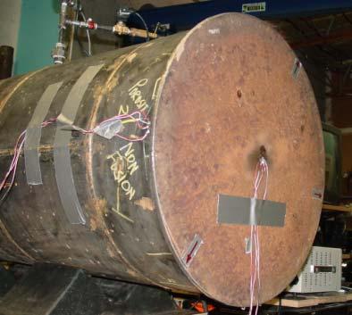
7 Test Specimens 7


8 Weld Details 8
9 Nondestructive Examination All test were inspected using PT and VT. Test #1 also included radiography. Minor undercut in some tests (<5% wall thickness). Lack of penetration, porosity. Initial flaws were not repaired. Flaws were not initiation sites and did not affect failure results. 9


10 Experimental Procedure Cycle between zero and 60psig (0.414 MPa) Tests conducted full of water Pressure range produces structural stress < 2*Sy Repaired flaws and continued testing if possible 10


11 Failure Criteria Thru thickness crack with visible leakage. Same failure criteria as Markl, but different than typical structural fatigue tests. Additional failures which occurred adjacent to fatigue repairs are not included in results. 11
12 Experimental Results Pressure range is constant for all tests, but stress varies between tests due to as-built weld dimensions and plate thickness. Expected larger scatter, but didn t see it. Didn t see difference between TIG and MIG welded test specimens. Largest scatter is seen within Joint #4 this illustrates the variability of single sided joints. 12
13 13

14 Fatigue Failures in Double Sided Joints Failures in Joints #1, #2, #3, and #5 began at inside weld toe and extended to outer weld toe. 14

15 Joint #4 Fatigue Failures Single Sided Weld Failures in single sided joint initiated at fillet like root reinforcement and extended thru face of outer weld. No weld throat or root failures. No failure from external toe (compressive stress range?) 15
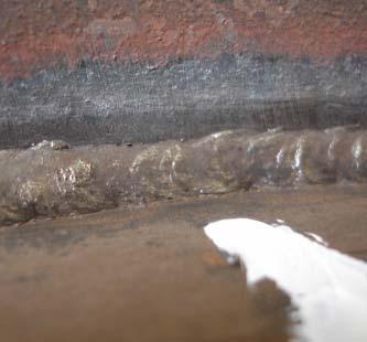

16 Root Reinforcement in Joint #4 16
17 Summary of Testing Five test specimens 19 unique failure sites Repeatable test results Stainless and Carbon Steel Double and Single Sided Welds 17
18 FEA Analysis and Fatigue Design Rules 18

19 Finite Element Analysis Axisymmetric models used to determine stress As-built dimensions used in all calculations. Several models constructed for each test: Structural stress, extrapolations, etc Notch stress (0.50mm and 1.0mm radius) Stress on weld throat 19
20 FEA Stress Results Peak Stress w/ 0.5mm Radius Peak Stress w/ 1.0 mm Radius Direct Membrane Stress (Linearized membrane normal to weld) Direct Bending Stress (Linearized bending normal to weld) Direct Structural Stress (Linearized stress normal to weld) EN Extrapolated Stress Master Curve Equivalent Stress Master Curve Eq. Pseudo Stress (with Neuber s rule applied) Summary of finite element stress results, psi (MPa) Joint #1 Toe of Fillet 135,950 (937.34) 111,114 (766.10) 1,641 (11.31) 70,952 (489.20) 72,593 (500.51) 72,691 (501.19) 76,553 (527.81) 86,560 (596.81) Joint #2 Toe of Fillet 129,380 (892.04) 106,554 (734.66) 1,596 (11.00) 65,598 (452.28) 67,194 (463.29) 67,292 (463.96) 71,353 (491.96) 79,582 (548.70) Joint #3 Toe of Fillet 128,574 (886.49) 105,448 (727.04) 1,612 (11.11) 65,221 (449.68) 66,834 (460.80) 66,932 (461.48) 70,803 (488.17) 78,861 (543.70) Toe of Fillet 107,710 (742.63) 86,776 (598.30) 1,559 (10.75) 56,480 (389.42) 58,039 (400.16) 58,124 (400.75) 61,676 (425.24) 67,282 (463.89) Joint #4 Root or Throat 85,142 (587.03) 61,780 (426.96) (2.64) 20,055 (138.27) 20,272 (139.77) Toe of Root Reinf. 82,963 (572.01) 71,117 (490.33) 1,121 (7.73) 34,845 (240.25) 35,966 (247.98) 36,066 (248.67) 41,293 (284.70) 43,728 (301.49) Joint #5 Toe of Fillet 117,446 (809.76) 95,846 (660.83) 1,411 (9.73) 57,149 (394.03) 58,560 (403.76) 58,651 (404.38) 63,847 (440.21) 69, (482.43)
21 Fatigue Design Rules Fatigue design methods used in comparisons: ASME Section VIII, Division 2, Appendix 5 using 0.50 mm effective weld radius. IIW Notch Stress Method using 1.0 mm effective weld radius and FAT 225. PD 5500 Curves F and W EN Curves 71 and 40 API 579 Curves 63 and 40 Master S-N Method Master S-N Method with Neuber s correction 21
22 Some notes on fatigue rules ASME is dependent upon notch radius, but still conservative for 0.5mm and 1.0mm. Plasticity correction factors not used since structural stress < 2*Sy For Master S-N method, plasticity correction factors are applied for structural stress > 1.0*Sy IIW Notch stress method only validated for plate thicknesses 5mm and greater. Environmental effects (if any) are not included. 22
23 Design Comparison with Test Results 23
24 Design Comparison with Test Results 24
25 Design Comparison with Test Results 25
26 Design Comparison with Test Results 26
27 Design Comparison with Test Results 27
28 Summary of Fatigue Calculations ASME, PD 5500, EN 13445, API 579 are conservative in all cases. IIW Notch Stress method is non-conservative in four test cases. Master S-N method is borderline conservative/nonconservative in these tests. ASME allows significantly greater fatigue lives for stainless steel. 28
29 Discussion of Results 29
30 Mean Curve Comparisons Do we have enough data to compare against mean curves? Carbon steel data matches ASME mean curve Stainless steel data is lower than current ASME curves for stainless steels Estimating mean curve by +2 curve classes for structural methods didn t produce good comparison Master S-N mean curves are higher than failure data (with and without Neuber s correction) 30
31 ASME Mean Curve for Carbon Steel 31
32 ASME Mean Curve for Stainless Steel 32
33 Master S-N Mean Curve Predictions Weld Joint Mean Curve Mean Curve w/ Neuber s Average Cycles to Failure #1 83,527 56,848 30,725 #2 104,067 73,920 37,853 #3 106,611 76,051 31,384 #4 574, , ,663 #5 123, , ,486 33
34 Stainless Steel Significant variation in the treatment of stainless steel vs. carbon steel fatigue life. Current ASME mean curve may over predict fatigue life. Jaske & O Donnell mean curve matches test data. Structural stress methods are very conservative for the current test. Literature is mixed, although latest research shows equivalent fatigue lives. 34
35 Single Sided Welds So simple, yet so complex. Idealized during design, but rarely ideal in the end. Difficult to control quality at weld root. Many potential failure sites to consider. 35
36 Single Sided Welds Application of throat stress calculations for high bending stress conditions is not clear...the load carried by the weld divided by the throat area. per PD
37 Thickness Effects Are both the following statements true? Fatigue life reduces with increasing thickness. Decreasing thickness results in increased fatigue life. If the second statement is true then Is there a reasonable limit to the increased fatigue life for thin plate geometries? 37
38 Thickness Effects All structural stress methods utilize a thickness correction in consideration of size effects. PD-5500, EN 13445, API 579 only apply correction factor above a reference value (near 25mm). Master S-N method applies thickness correction thru entire range of thicknesses. At plate thickness less than 0.25, Master S-N correction provides significant increase in allowable cycles. 38
39 Influence of Thickness Corrections 39
40 Thickness Effects DeJesus tests suggest thickness effects are less significant in thin plate failing at low cycles. Research by Gurney suggest thickness correction extends into lower thicknesses, but a limit does exist. Gurney showed that thickness effects are not as apparent at lower cycle life when subjected to bending stress. 40
41 Conclusions Code methods are conservative for these test results. IIW notch stress method and Master S-N curve were the exception. ASME Mean curve matches test data. Master S-N is significantly greater. Single sided welds are difficult to predict and control Weld throat failure criteria needs to be clarified for bending dominant stress field. The relationship between thickness effects and cycles to failure needs further review. Fatigue of stainless weldments needs to be harmonized. 41
42 What is next? Further testing: Study thickness effects. More stainless steel tests both TIG and MIG welded. Environmental effects? Test similar welds and thicknesses in structural type tests to full section failure. 42
43 Questions? Available for download at: 43