Phase Transformation in Materials
|
|
|
- Lionel Lester Riley
- 5 years ago
- Views:
Transcription
1 2015 Fall Phase Transformation in Materials Eun Soo Park Office: Telephone: Office hours: by an appointment 1
 Both are ideal soln.")
2 - Equilibrium in Heterogeneous Systems G 0 β > G 0 α > G 0 α+β α + β separation unified chemical potential - Binary phase diagrams 1) Simple Phase Diagrams H = 0 H = 0 Assume: (1) completely miscible in solid and liquid. (2) Both are ideal soln. L mix S mix 2) Variant of the simple phase diagram l H α l > > 0 H α mix < H mix < 0 mix H mix miscibility gab Ordered phase 2
3 1.5 Binary phase diagrams 5) Phase diagrams containing intermediate phases 3
4 1.5 Binary phase diagrams 5) Phase diagrams containing intermediate phases 4
5 The Gibbs Phase Rule For Constant Pressure, P + F = C single phase F = C - P + 1 = = 2 can vary T and composition independently two phase F = C - P + 1 = = 1 can vary T or composition 3 eutectic point F = C - P + 1 = = 0 can t vary T or composition 5
6 * Vacancies increase the internal energy and entropy Gibb s free energy Equilibrium concentration will be that which gives the minimum free energy. at equilibrium dg dx e V X = X V V = 0 : adjust so as to reduce G to a minimum e H T S + RTln X = 0 V V V A constant ~3, independent of T e SV HV XV = exp exp R RT putting G = H T S e G XV = exp RT V V V V Rapidly increases with increasing T In practice, H V is of the order of 1 ev per atom and X V e reaches a value of about 10-4 ~10-3 at the melting point of the solid Fig Equilibrium vacancy concentration. : adjust so as to reduce G to a minimum
7 a. Effect of T on solid solubility X e B = Aexp Q RT a) T e X B b) It is interesting to note that, except at absolute zero, X B e can never be equal to zero, that is, no two compo -nents are ever completely insoluble in each other. A is virtually insoluble in B. T Solid solution α precipitate β b. Influence of Interfaces on Equilibrium: extra ΔG Gibbs-Thomson effect (capillarity effect): ΔG = ΔP V For small values of the exponent, X X r= r B r= B G = 2γV r 2γVm 2γV = exp( ) 1+ RTr RTr m m Ex) γ=200mj/m 2, V m =10-5 m 3,T=500K X r = 1 + X 1 r( nm) For r=10 nm, solubility~10% increase 7
8 Gibbs-Duhem equation: Calculate the change in (dμ) that results from a change in (dx) Gibbs-Duhem equation for a binary solution X dµ + X dµ = A A B B 0 Comparing two similar triangles, dµ dµ B d( µ B = = X X 1 Substituting right side Eq. & Multiply X A X B Gibbs-Duhem Equation X A, X B vs. dμ A, dμ B γ A, γ B a A, a B A µ A B A ) dg µ B µ A = dx B 1 2 dg A µ A B µ B A B 2 B X d = X d = X X dx dx 2 dg dln γ A dln γ B X AX B = RT 1 RT = + dx dln X A dln XB, d 2 G/dX 2 d 2 G/dX B2 =d 2 G/dX A 2 Eq
9 Total Free Energy Decrease per Mole of Nuclei G 0 : Driving force for phase transformation of system Driving Force for Precipitate Nucleation G V 1 G = V V G V α β α β µ A X A µ B X B G = + β β β β G 2 = µ A X A + µ B X B : Increase of total free E of system by forming β phase with composition X β B (Q point) G n m = For dilute solutions, n G 2 G 1 per unit volume of G X where X = X X : Decrease of total free E of system by removing a small amount of material with the nucleus composition (X Bβ ) (P point) G V X T (length PQ) 0 e β : driving force for β precipitation undercooling below T e 9 β G r
10 Contents for today s class What are ternary phase diagram? Diagrams that represent the equilibrium between the various phases that are formed between three components, as a function of temperature. Normally, pressure is not a viable variable in ternary phase diagram construction, and is therefore held constant at 1 atm. 10
11 Gibbs Phase Rule for 3-component Systems 11

12 Gibbs Triangle An Equilateral triangle on which the pure components are represented by each corner. Concentration can be expressed as either wt. % or at.% = molar %. X A +X B +X C = 1 Used to determine the overall composition 12
13 Overall Composition 13
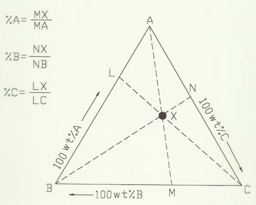
14 Overall Composition 14
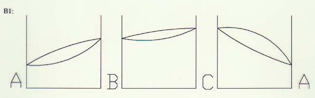
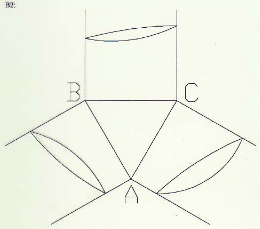
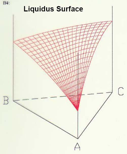
15 Ternary Isomorphous System Isomorphous System: A system (ternary in this case) that has only one solid phase. All components are totally soluble in the other components. The ternary system is therefore made up of three binaries that exhibit total solid solubility. The Liquidus surface: A plot of the temperatures above which a homogeneous liquid forms for any given overall composition. The Solidus Surface: A plot of the temperatures below which a (homogeneous) solid phase forms for any given overall composition. 15
16 Ternary Isomorphous System 16

17 Ternary Isomorphous System 17

18 Ternary Isomorphous System 18
19 Ternary Isomorphous System 19


20 Ternary Isomorphous System Isothermal section F = C - P 20

21 Ternary Isomorphous System Isothermal section 21
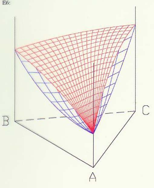
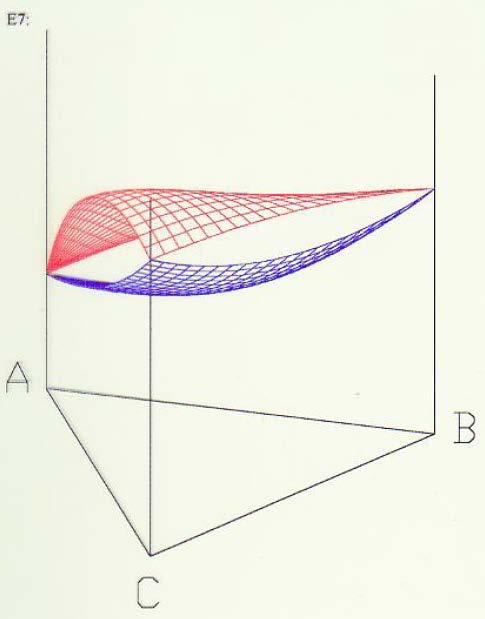
22 Ternary Isomorphous System Isothermal section F = C - P Fig (a) Free energy surface of a liquid and three solid phases of a ternary system. (b) A tangential plane construction to the free energy surfaces defined equilibrium between s and l in the ternary system (c) Isothermal section through a ternary phase diagram 22

23 Ternary Isomorphous System Locate overall composition using Gibbs triangle 23
24 24


25 Ternary Eutectic System (No Solid Solubility) 25


26 Ternary Eutectic System (No Solid Solubility) Liquidus projection 26
")
27 Ternary Eutectic System (No Solid Solubility) 27
")
28 Ternary Eutectic System (No Solid Solubility) 28
")
29 Ternary Eutectic System (No Solid Solubility) 29
")
30 Ternary Eutectic System (No Solid Solubility) 30
")
31 Ternary Eutectic System (No Solid Solubility) 31
")
32 Ternary Eutectic System (No Solid Solubility) 32
33 Ternary Eutectic System (No Solid Solubility) T= ternary eutectic temp. A C L+A+C L+A+B L+B+C B 33
")
34 Ternary Eutectic System (with Solid Solubility) 34
")
35 Ternary Eutectic System (with Solid Solubility) 35


36 Ternary Eutectic System (with Solid Solubility) 36


37 Ternary Eutectic System (with Solid Solubility) TC 37


38 Ternary Eutectic System (with Solid Solubility) 38


39 Ternary Eutectic System (with Solid Solubility) 39


40 Ternary Eutectic System (with Solid Solubility) 40


41 Ternary Eutectic System (with Solid Solubility) TC 41

42 Ternary Eutectic System (with Solid Solubility) T= ternary eutectic temp. C L+β+γ L+α+β L+α+γ 42
 정해솔학생제공자료참조 : 실제")

43 Ternary Eutectic System (with Solid Solubility) 정해솔학생제공자료참조 : 실제 isothermal section 의온도에따른변화 43
")

44 Ternary Eutectic System 3) Solidification Sequence: liquidus surface 44
45 * Vertical section Ternary Eutectic System * The horizontal lines are not tie lines. (no compositional information) * Information for equilibrium phases at different tempeatures 45
46 < Quaternary phase Diagrams > Four components: A, B, C, D Assuming isobaric conditions, Four variables: X A, X B, X C and T A difficulty of four-dimensional geometry further restriction on the system Most common figure: equilateral tetrahedron 4 pure components 6 binary systems 4 ternary systems A quarternary system 46
47 * Draw four small equilateral tetrahedron formed with edge lengths of a, b, c, d a+b+c+d=100 %A=Pt=c, %B=Pr=a, %C=Pu=d, %D=Ps=b 47
48 * Incentive Homework 1 Please submit ternary phase diagram model which can clearly express 3D structure of ternary system by October 17 in Bldg You can submit the model individually or with a small group under 3 persons. * Homework 1 : Exercises 1 (pages 61-63) Good Luck!! 48

49 49