AAO MCP Substrate Development at ANL. High Energy Physics Division, Materials Science Division Argonne National Laboratory Friday, June 11, 2010
|
|
|
- Shana Summers
- 5 years ago
- Views:
Transcription
1 AAO MCP Substrate Development at ANL Seon W. Lee and H. Hau Wang High Energy Physics Division, Materials Science Division Argonne National Laboratory Friday, June 11, 2010
2 Contents What is AAO? Advantage of AAO MCP Roadmap for the Development of AAO based MCP Develop fabrication process Optimize L/D & open area ratio to achieve maximum gain Building funnel shape on channel entrance Scale up to build 8 X 8 AAO MCP Current Status & Results Future Plan & Milestones 2


3 What is AAO(Anodic Aluminum Oxide)? Self organized hexagonally closed packed nano scale pores formed by anodizing aluminum in acidic electrolyte Intrinsic pore Growth Direction 3 D model of AAO /research.html Cross section of AAO 3 Atomic Force Microscopy (AFM) image on top of AAO pores
4 Advantage of AAO based MCP 1. Al is inexpensive 2. Pore diameter can be varied in wide range : 20nm~500nm (intrinsic pores), >500nm (Micromachined pores by lithography and etching) Laser Writer (32.8mm), 8 X8 Large scale > Photomask Bottom up Top down 4


5 Advantage of AAO based MCP 3. Intrinsic pores are helpful to create vertically straight pores by wet etching Intrinsic Pores 20~500nm Micromachined Pores (500nm ~ 40um) Cross-section of Etched Pores Si etching: not possible to etch deep trench with high aspect ratio 4. Funnel entrance can be fabricated on one face Intrinsic pores have naturally funnel shape entrance To build funnel entrance : By nanoimprint, apply varying voltage mnemosyne.umd.edu/.../article3773.large.jpg 5
6 Roadmap for the development of AAO based MCP Develop fabrication process to to create large scale micromachined pores Optimize for for max. gain: L/D by by varying diameter of of micromachined pores and thickness of of AAO Open area ratio Build funnel shape on on channel entrance Scale up up :: 8 8 X 8 8 6


7 AAO MCP Fabrication Process Self-ordered alumina by 2-step anodization - experimental procedures Selective dissolution of the formed oxide layer Chromic acid/phosphoric acid Electropolishing is carried out HClO4/EtOH Second anodization 1~2 days First anodization using 0.3 M sulfuric acid Pore widening In phosphoric acid 7

")

8 Photolithography on Aluminum anodic oxide (AAO) using laser (400nm) writer Mask design : L Edit Micromachined Pore 8
 Header and Footer\" to add your organization, sponsor, meeting name here; then, click \"Apply to All\" 9")
9 2um, 5um, 10um hcp (hexagonal closed packed) pores patterns Diameters of pores and pore to pore distance can be varied by drawing pattern Go to Insert (View) Header and Footer" to add your organization, sponsor, meeting name here; then, click "Apply to All" 9


10 Optimize to maximize gain Electron multiplication is determined by a channel aspect ratio (L/D). Channel aspect ratio: the ratio of Length to Diameter L/D should be adjusted to maximize the electron amplification Maximize open area ratio D L Open Area Ratio : 15.33% L/D = Open Area Ratio : 64.28% L/D = 10 Open Area Ratio : 28.16% L/D = 10 10


 Lee")
11 Diameter of pores, pore-to-pore distance, thickness of AAO 275 um Lee et al. Nat Materials, vol 5, p741 ( 2006) Lee et al. Nat Materials, vol 5, p741 ( 2006) 11
12 Aspect ratio Required AAO thickness (in m) to meet the aspect ratio (L/D) White areas are straight forward Aspect ratio L/D Pore size D um 40 um 80 um 200 um 400 um 800 um um 60 um 120 um 300 um 600 um 1200 um um 80 um 160 um 400 um 800 um 1600 um um 100 um 200 um 500 um 1000 um 2000 um Green area is considered possible range for AAO MCP 12

13 Open area Pore size hcp structure a pore diameter Pore to pore distance Calculated open ratio Accomplishment a 2 a 22.7 % Accomplished a 1.5 a 40 % Accomlished for small area test sample a 1.25 a 58 % Accomlished for small area test sample a 1.10 a 78.7 % Possible, end of 2 nd year a a 90.7% Possible only with funnel Open area up to 80% is feasible. 90% open area is only possible if funnel shaped entrance can be prepared. 13

14 Funnel Shape Entrance For intrinsic pores 14


15 Funnel Shape entrance for intrinsic pore Nanoimprint technique & Varying voltage Lee et al. Nat Materials, vol 5, p741 ( 2006) Lee et al. Nat Nanos, vol 3, p234 ( 2008) Large intrinsic pores hard anodization pore to pore distance 440nm pore diameter 300nm 15

16 Scale up : 8 X8 8 X 8 AAO MCP : Need to design teflon cell to grow large scale AAO
17 Current status of AAO MCP development at ANL 32.8 mm free standing AAO is being prepared. 4x4 mm 2 patterns, initially each pattern had different size of pores AAO (Al 2 O 3 ) 32.8 mm 17


18 Status of testable AAO based MCP at Argonne 32.8 mm free standing AAO Pore size : 20 um Open area ratio : 22.66% L/D : 10 18


19 1 st testable AAO based MCP at Argonne Optical Image 32.8 mm free standing AAO is ready Pore size : 20 um Open area ratio : 22.66% D/L : ~ 10 Front Back X10 X20 19

 Images of")


20 Current status of AAO MCP development at ANL SEM(Scanning Electron Microscopy) Images of etched 20 um pores, open area ratio 22.66% Open Area Ratio : 22.66% L/D = 10 Open Area Ratio : 22.66% L/D = 10 Front Back 20


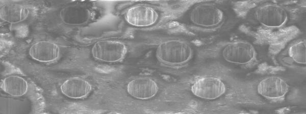
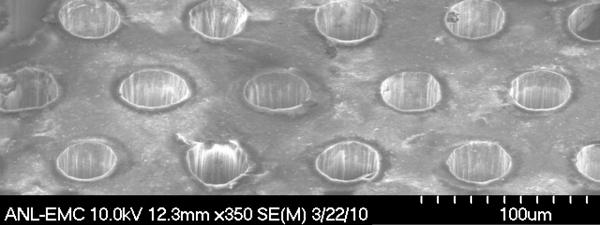
21 SEM images AAO with etched pores 20 m front 20 m back L/D = 10 L/D = m front 15 m back L/D = L/D =


22 SEM images 10 m front 10 m back L/D = 20 L/D = 20 8 m front 8 m back L/D = 25 L/D = 25 22

23 Open area ratio achieved: 64.28% Aspect ratio L/D=25 achieved Open Area Ratio : 15.33% L/D = Open Area Ratio : 28.16% L/D = 10 Open Area Ratio : 64.28% L/D = 10 8 m front 8 m back Open Area Ratio : 22.66% L/D = 25 Open Area Ratio : 22.66% L/D = 25 23
24 Milestones Year 1 (a) Achieve straight pores with diameter 0.7 micron (no funnel option), 40 <L/D< 100, and open area ratio 60 % > Toward large pore to pore distance, we are developing both intrinsic pore etching and nanoimprint techniques > intrinsic pore: any aspect ratio, micromachined pore > open area ratio 60% was achieved for small area test sample. (b) Demonstrate the feasibility of making AAO funnels suitable for photo cathode deposition > intrinsic pores naturally come with funnel shape (c) Produce blanks of 32.8 mm AAO plate for tests and MCP development. > 20 um pores AAO MCP samples delivered to the ALD group Year 2 (a) Achieve straight pores with diameter 1 micron (no funnel option), 40 <L/D< 100, and open area ratio 80 %; (b) If funnels are feasible, achieve straight pores with diameter 1 micron, 40 <L/D< 100, and open area ratio 90 %; (c) Demonstrate gain > 1000, uniformity to < 15% in an AAO/ALD plate. 24
25 Plans for testable AAO based MCP in near future We started to provide testable AAO based MCP Currently making samples To increase open area ratio To increase aspect ratio ALD Qing, Anil Test at APS measure amplification gain Acknowledgments DOE/HEP 25

 large")

26 The First Strike Problem Curved pores RIE (Reactive Ion Etching) large scale pores Nanotechnology 18 (2007)