Development of a Solid State Joining Process Incorporating Bi-Axial Deformation: Translationally Assisted Upset Welding (TAUW)
|
|
|
- Avis Roberts
- 5 years ago
- Views:
Transcription


1 Development of a Solid State Joining Process Incorporating Bi-Axial Deformation: Translationally Assisted Upset Welding (TAUW) April 29, 2014 Jerry E. Gould Technology Leader Resistance and Solid State Welding EWI ph: jgould@ewi.org Sam Lewis Applications Engineer Resistance and Solid State Welding EWI ph: slewis@ewi.org Page 1


2 Non-Rotating Solid-State Welding Technologies Process definitions Adaptable to non circular sections Heating stage Forging stage Development of a solid-state bond Single shot processing Advantages of solid-state processing Properties Product metallurgy Productivity Typical process variations Flash butt welding Resistance butt welding Resistance projection welding Hot pressure welding Linear friction welding
 cycle times High productivity Well adapted to carbon steels Application of temper cycles")

3 Characteristics of Upset Welding (UW) Processses Mature technology Transformer and timer based Single direction forging systems Widely used in industry today Implicit low scrap rates Process inputs Current Force Time Advantages Well established technology Rapid (seconds) cycle times High productivity Well adapted to carbon steels Application of temper cycles Disadvantages Limited widths and areas Uni-directional forging Large upset volumes Max strains on the order of 1000% Sensitive to material resistivity Not adaptable to a wide range of materials Measured upset strains as a function of location in a resistance butt weld Upset butt ring welding system. Courtesy Paramount Stamping and Welding Deformation profile on a typical steel upset butt weld


4 Characteristics of Linear Friction Welding (LFW) New technology Concepts derived from direct drive friction welding Young technology, developed only ~15 years ago Modern systems largely hydraulically based Process inputs Normal force Translational frequency Translational displacement Deceleration sequence for aligning parts Advantages High deformations (~10 s of thousands of percent) along bond line Weld morphologies similar to other friction welds Rapid (seconds) cycle times High productivity Highly localized upsets Adaptable to a wide range of materials Disadvantages High equipment costs Complexity of controls and tooling Equipment scale Final part alignments Inability to apply post weld heat treatments Linear friction welding system. Courtesy Thompson Friction Welding Machines Morphology of Ti alloy linear friction welds. Ma., Li., and Yang Materials & Design, V30(6): Titanium alloy linear friction welds. Courtesy Thompson Friction Welding Machines

5 Definitions of Translationally Assisted Upset Butt Welding (TAUW) Translationally assisted upset butt welding (TAUW) Mechanistically similar to Upset Butt Welding Introduction of lateral motion Process heating largely accomplished through resistance mechanisms Lateral motion to add a second degree of freedom during deformation Relatively low lateral motion frequencies Equipment costs comparable to UBW Bond line strains (and weld quality) approaching LFW Reductions in material loss compared to UW Scope of the current program Adapt an existing UW system for translational action Design and acquisition of a lateral motion system Integration into the existing machine Development of necessary tooling Definition of a candidate application Identification of program stakeholders Review of existing and potential applications Selection of materials and geometries for study Process demonstrations Manufacture of sample welds Without translation With translation Assessment of processing requirements Microstructures of resulting joints


6 Candidate Applications and Materials Specific applications Blisks Aircraft structural elements Wheels Materials Titanium alloys Nickel base alloys Steels Down-selected applications Ti-6Al-4V 1018 steel Nominal 6-mm x 50-mm cross section Blisk assembly with LFW attached blades. Courtesy MTU Aero Engines Stamped and welded truck wheel rims. Courtesy Accuride Wheels


7 Design and Integration of the Translational Motion System Definition of system requirements Based on the selected application 36-kN upset force 70-kN lateral force 6-mm lateral displacements Base welding system Thompson F3 welding frame 40-kN max upset force 3ΦDC power supply Translational action Parker Hannfin system Compax3F control/drive VPak power unit 100-mm diameter cylinder D3FH proportional valve Probe and linear alignment coupler for feedback control Electric servo-drive system. Courtesy Parker-Hannifin Corporation Thompson F3 upset butt welding frame available at EWI


8 Tooling and Software Developed for Allowing Translational Motion Tooling developed for TAUW Translational slide assembly built onto existing platens Support brackets to accommodate reactive translational torques Integrated conductive path on the translating clamp Simplified clamps for restraining test workpieces Software integration for the final system Translational motion software provided by Parker-Hannifin Interface for programming displacement, frequency, and numbers of motions System initiated from the main welding control Sequencing between current and the translational and upset motions Instrumentation for monitoring Weld current Lateral displacement Forge displacements Schematic representation of the servo-drive and tooling for translational upset butt welding Clamps containing workpieces mounted on the Thompson F3 welding frame
9 Upset Butt Welding (UW) Trials on Ti-6Al-4V Weld no. Force (kn) Stickout per side (mm) Current (ka) Up-slope time (ms) Weld time (ms) TAUW Motion delay * (ms) Upset dist. (mm) Comments n - - No weld n - - No weld n Left side low n Expulsion n Left side still low n - - Added 0.25-mm shim, weld checker didn't read properly no weld, good alignment n Severe heat imbalance, bottom hot n - - No weld n - - No weld n - - No weld n - - No weld n - - Good upset, sectioned n Test Samples n - - Test Samples n Test Samples n - - DAQ based definition of timing for lateral motion n Ti-6Al-4V coupons 6-mm x 50-mm cross sections Iterative welding trials Initial practices based on steels 5 to 15-mm stickout 75 to 150 MPa upset stresses Extended weld times (~3- sec) required Use of upslope to prevent first cycle expulsion Extended upset (>2x wall thickness required for good welds


10 Upset Butt Welding (UW) Trials on Ti-6Al-4V 25-mm Full faced bonding Width Through thickness Non-uniform heating across the width Differential flash profile Bifurcated at the center Continuous at the edges α+β base material Partially transformed HAZ in the forge region Narrow β-transformed zone along bond line Bond area ~3x the base material thickness ~240% bond line strain Extensive flash removal required
11 Translational Upset Butt Welding (TAUW) Trials on Ti-6Al-4V Weld Stickout Weld Force Upslope Weld time current offset strokes upset Bend test Comments (mm) (kn) (ms) (ms) (ka) (mm) (mm) (kn) no weld bend failed at bond line bond line failure migrated into base material * Sample used for both met and bend testing No heating visible from current no weld no weld no weld Tensile test performed on this sample * Sample sectioned lengthwise, 1/2 used for bend testing, 1/2 for met evaluations. The reported bend strength is for this half sample width. Quality measures primarily through bend testing Heating times varied from 750-ms to 3000-ms Translational action at the end of the heating cycle Page 11 Process robustness with greater mechanical oscillations Best practices submitted for metallographic examination and tensile testing
 Upset Disp.")
 321 784 0.")
12 General Characteristics of TAUW on Ti-6Al-4V Current (ka) Transv. Disp. (mm) Upset Disp. (mm) 2 1 Displacement (mm) Current (ka) Time (ms) Ultimate Strength (MPa) % Yield Strength (MPa) Elongation Reduction Failure (%) of Area (%) Location Weld Weld Page 12

13 Visual Observations During TAUW of Ti-6Al-4V Page 13
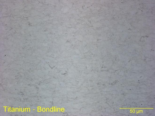
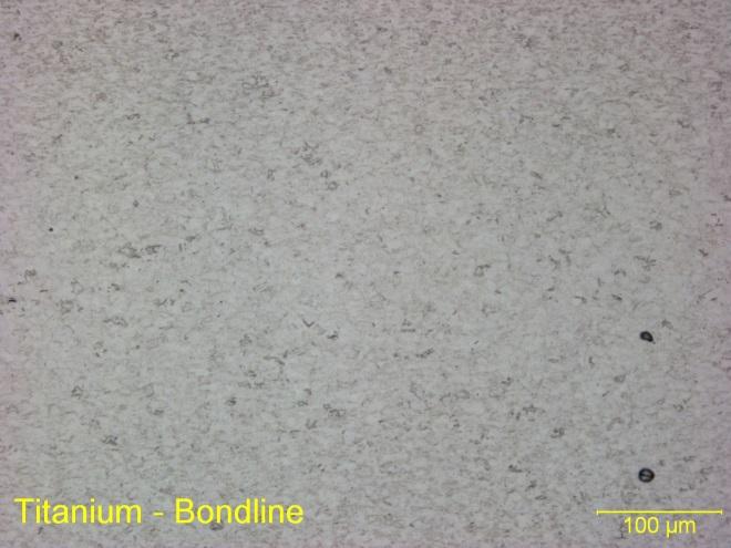
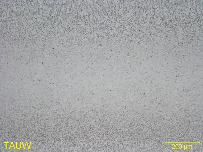
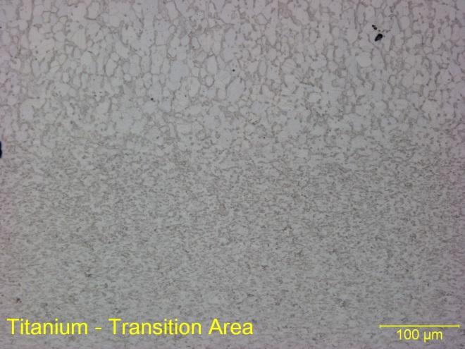
14 Microstructural Characteristics of TAUW on Ti-6Al-4V Page 14
15 Translational Upset Butt Welding (TAUW) Trials on 1018 Steel Weld Stickout Weld Upslope Weld time Current Offset Strokes Upset Bend test Comments (mm) Force (kn) (ms) (ms) (ka) (mm) (mm) (kn) Hit with hammer, no bend before break approx 5 deg bend before break deg bend no break deg bend before break deg bend before break Cold, clamps not tightened propoerly repeat of conditions from sample 19 for tensile test Practices based on UW for steels Use of a 4-kA, MFDC power supply Preliminary quality evaluations through manual bend testing Higher currents compared to Ti-6Al-4V Reduced stroke lengths Translational oscillations begin at the end of the heat time Best practices submitted for metallographic examination and tensile testing Page 15
 5 4 3 2 1 0 1 2 3 4 5 Displacement (mm) Ultimate Strength (Mpa) 0.")
16 General Characteristics of TAUW on 1018 Steel Current (ka) Current Upset Disp. Transverse Disp Time (ms) Displacement (mm) Ultimate Strength (Mpa) 0.2% Yield Strength (Mpa) Elongation (%) Reduction of Area (%) Failure Location Weld Weld Page 16

17 Visual Observations During TAUW of 1018 Steel Page 17
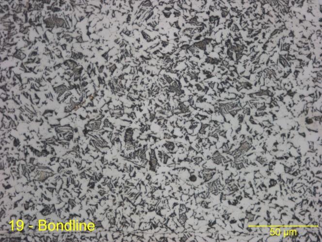
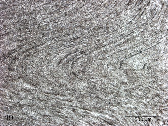

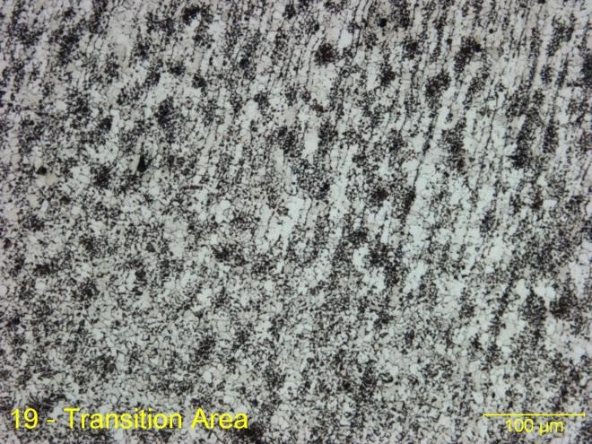
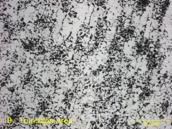
18 Microstructural Characteristics of TAUW on 1018 Steel Page 18

19 Hardness Distributions Tensile Behavior Relationships on the Steel Samples Stress (MPa) Test 1 Test % 1.0% 2.0% 3.0% 4.0% 5.0% 6.0% 7.0% Engineering Strain 1-mm Yield strengths comparable to the base material Relatively limited elongation compared to the base material Impact of metallurgical notches around the weld Page 19 Very narrow HAZ Hardness values maximize around 350-VHN to 375-VHN Through thickness uniformity in hardness variations

20 Analysis of Resistance Heating During TAUW Thermal analysis based on previous activity for resistance spot welding One dimensional analysis Pure resistive heating Sinusoidal temperature distribution between the dies Peak temperature at the end of resistance heating Influence of thermal conductivity Page 20
21 Temperature Dependent Yield Strengths of Ti-6Al-4V and 1018 Steel Yield Strength (Mpa) Temperature (oc) 62 Asinh 420 Asinh Ti YS data Ti 6Al 4V 1018 Steel Temperature dependent yield strength data collected from the literature Extensive softening at higher temperatures Ti-6Al-4V typically stronger at all temperatures Data fit wit sigmoidal equations Equations can be integrated with developed thermal solutions Page 21
 500 450 400 σti 350 σsteel 300 250 200 150 100 50 0 8 6 4 2 0 2 4 6 8 Position (mm) Θp-steel = Θp-ti = k e = k s = k Ti = stickout = 1100 C 1450 C 367 W/m-K 41.9 W/m-K 6.7 W/m-K 7.")
22 Temperature and Yield Strength Variations for TAUW on Ti-6Al-4V and 1018 Steel Temperature ( o C) Yield Strength (Mpa) Tti 400 Tsteel Position (mm) σti 350 σsteel Position (mm) Θp-steel = Θp-ti = k e = k s = k Ti = stickout = 1100 C 1450 C 367 W/m-K 41.9 W/m-K 6.7 W/m-K 7.6 mm Page 22

23 Translationally Assisted Upset Butt Welding Conclusions TAUW a new technology Augmented strains compared to UW Bonding at reduced upset distances Hardware development to add translational action Comparisons with conventional UW Demonstrations using both Ti-6Al-4V Primary upset occurring during translational action Current flow providing preheating Elimination of shear peaks Limited translational action required Modeling demonstrating differences in heating for the two material systems Page 23
24 Questions? Jerry E. Gould Technology Leader Resistance and Solid State Welding EWI ph: Page 24

25 Since the early 1980s, EWI has helped manufacturers in the energy, defense, transportation, heavy manufacturing, and consumer goods industries improve their productivity, time to market, and profitability through innovative materials joining and allied technologies. Today, we operate a variety of centers and consortia to advance U.S. manufacturing through public private cooperation.