An Integrated Coupled-Physics Framework for Performance and Life Prediction of Supercritical CO2 Turbomachines
|
|
|
- Gavin Morrison
- 5 years ago
- Views:
Transcription
1 CSP An Integrated Coupled-Physics Framework for Performance and Life Prediction of Supercritical CO2 Turbomachines energy.gov/sunshot Azam Thatte, Lead Research Scientist - GE Global Research
2 Acknowledgements * Work performed under U.S. DOE (EERE) PREDICTS program award # DE-EE Co-authors: Adrian Loghin, Etienne Martin, Voramon Dheeradhada, Youngwon Shin, Balajee Ananthasayanam Partners : Southwest Research Institute ( Jeff Moore, Tim Allison) 2
3 Overview FOA: PREDICTS (Physics of Reliability: Evaluating Design Insights for Component Technologies in Solar ) Award Number:DE-EE PI : Azam Thatte ( GE Global Research ) Partner : Southwest Research Institute Project Duration: Oct 2013 Sept 2016 Project Budget : $ 2.41 Million ( 20 % cost share by GE) 3
4 Problem Statement and Value Proposition Scalable Supercritical CO2 (sco2) turbine expected to provide a major stepping stone for achieving CSP power at $0.06/kW-hr LCOE. Energy conversion efficiency > 50%, Total power block cost < $1,200/kW installed. Turbomachinery must have a 30-year life ~ 11,000 thermal cycles. Under another Sunshot program (# DEEE ) GE and SWRI developing this 10MWe sco2 turbine. Two key components critical to high efficiency of these sco2 power cycles are: 1. Hybrid gas bearing (HGB). 2. Dry gas seal (DGS). HGB ~ 5 % efficiency gain ( rotordynamics & aero efficiency ), avoids 500 KW parasitic losses. HGB Allows integral compressor reduces cost. DGS ~ 10 % improvement in efficiency (reduced leakage + generator windage) DGS No need of multi-stage intercooled compressor to recompress leakage. 4

5 10 MWe GE-SWRI Sunshot sco2 Turbine 5

6 Why Hybrid Gas Bearing and Dry Gas Seal in sco2 Turbines? Hybrid Gas Bearing ~ 3% efficiency gain Rotordynamics Needs mid-span support for high power densities. Oil bearings need two sets of seals combined parasitic load ~ 500 KW Larger L/D longer blades for same annular area aero efficiency No need of separate compressor package reduced cost. 6


7 Why Hybrid Gas Bearing for sco2 Turbine? With Traditional Oil Bearings With Hybrid Gas Bearing HGB brings sco2 rotor down into comfortable CSR regime 1) Shorter Rotor Reduced rotor flexibility rotordynamically stable 2) For same L/D, longer blades aero efficiency. 3) No parasitic losses from seals 500 KW 4) Gas less viscous Lower power loss in the bearing 5) Midspan bearing allows integral compressor reduced cost. 7
 Unlike steam Rankine cycles, leaked CO2 must be compressed as vapor back to main")

8 Why Dry Gas Seal in sco2 Turbine? ~ 10 % improvement in overall system efficiency ( leakage + generator windage) Unlike steam Rankine cycles, leaked CO2 must be compressed as vapor back to main compressor inlet pressure of ~80 bar. Need multi-stage intercooled compressors Large auxiliary compression load efficiency penalty (figure on right ) 0.6% total end seal leakage reduces net cycle efficiency from 50% to about 48.4%. High temperature DGS eliminate need for thermal management schemes reduce rotor span better L/D better Aero efficiency & rotordynamics. Aid 500 MW scale sco2 turbine designs by allowing diameter DGS design which does not exists today. 8


9 Project Objectives Develop coupled physics performance and life prediction framework for sco2 turbomachines 9


10 Hybrid Gas Bearing Combine hydrostatic and hydrodynamic load support Flexure pivot tilting pad bearing for stability Maintain very tight film thickness ~ mil Bearing is soft-mounted on s-spring to provide compliance. Damping is achieved between the pad and supports via wire mesh to dissipate vibration energy 10


11 Hybrid Gas Bearing Performance Model Static Pressure: flow from supply pressure tube to bearing edge (guess recess pressure). Guess rotor position determine film thickness solve compressible Reynolds equation. Wire mesh damping and stiffness properties determined experimentally. Structural stiffness and damping matrices constructed from X,Y force equilibrium 11


12 Hybrid Gas Bearing Performance in sco2 Turbine Non-dimensional stiffness of HGB during sco2 operation Kxx = 235 Cxx = 89 Kxy = -2.6 Cxy = 21 Kyx = -5.1 Cyx = 29 Kyy= 312 Cyy= 48 Non-dimensional damping of HGB during sco2 operation Pressure F_static Gas_viscosity F_static_x_Pressure Rotor_rpm F_static_x_Gas_viscosity Rotor_rpm_x_Gas_viscosity Rotor_rpm_x_F_static Pressure_x_Gas_viscosity Rotor_rpm_x_Pressure F_dyn_Freq F_static_x_F_dyn_Freq F_dyn_Freq_x_Gas_viscosity Rotor_rpm_x_F_dyn_Freq F_dyn_Freq_x_Pressure % Contribution to P3 12


13 Model Validation (in Air) using Pressurized Rotordynamics Tests on Hybrid Gas Bearing Pad rotations High resolution strain gages Strain in S-Springs


14 Hybrid Gas Bearing Load Mission in sco2 Turbine Thin Film Physics + Rotordynamics + System Level Fluid-Thermal-Structural Loading Mission Cycle For Life Prediction 14


15 Dry Gas Seal Performance Models Assess Performance Risks Feed into Life Model Design Optimization for large MW sco2 turbines Thin Film Physics: Hydrodynamic Pressure at Interface Effect of Turbine Axial Transients p h P p h P r 12 r h p r r r Coupled Fluid-Structure Interaction: Tilt & Coning ND1 vibrations 15

16 Hydrodynamic Force & Stiffness Variation with Spiral Angle 16 16


17 sco2 Specific Perturbations Sonic Transition Density Mach # Variation Speed of Sound Thermal-Structural Risks Risks addressed through Advanced Models Supercritical Liquid Dry Ice. Sonic DGS interface Density Local speed of sound Mach # High Biot #, High Nusselt # Large thermal stresses, coning Flow Reversal 17
 Liquid-gas")
")
 3")
 to a complete")
 : Supercritical State 41 C 65 bar (b, c) :")
 : Pure gas phase CO2 remains as")
.")
18 sco2 Phase Change & Surface Tension Studies sco2 Phase Diagram Pressurization Path (1 2 3) Liquid-gas interface No meniscus No surface tension Supercritical State Gas Liquid De-Pressurization Path (3 4) Experimental Setup (a) (b) (c) Supercritical Gas Supercritical Gas 41 C 96 bar Supercritical Gas (d) 3 4 : Pressure reduced isothermally to cause CO2 transition from supercritical state (a) to a complete gas phase (d). (a) : Supercritical State 41 C 65 bar (b, c) : Crossing phase boundary, appearance of meniscus & surface tension (d) : Pure gas phase CO2 remains as pressure (65 bar) falls well below the critical pressure (73 bar). Program Information Summit on this 2016 chart is delivered with LIMITED RIGHTS in accordance with legend on the cover page. 18
19 Phase Change and 2-Phase Flow Model Liquid phase described using incompressible Navier-Stokes equations: Vapor phase described using Weak form of Navier Stokes Equation : State-of-the-Art Code developed in House. Study phase change risks in sco2 compressors. Nucleation vs Residence time scales. Design effective sco2 heat exchangers. Conduction Equation for the vapor phase: Condensation and erosion predictions. Boundary conditions at liquid-vapor phase boundary: 3 forces act on the interface natural boundary condition for liquid can be written as : reaction force due to the acceleration of the vapor away from the liquid surface Surface Tension Sum of pressure & viscous forces acting on the liquid from vapor 19


20 Phase Change and 2-PhaseFlow Model using Level Set Method Water Boiling CO2 Boiling Large local metal surface temp. rise. Uncertainty in HTCs Performance risks. Oxidation acceleration Life debit. Transition to film boiling 20

21 Phase Change and 2-PhaseFlow Model using Level Set Method 21
 P (bara) Seal Supply")

22 Dry Gas Seal Model Validation Tests in 10 MWe Sunshot sco2 Expander DGS panel + heating Inlet Side Exit Side Stream T ( C) P (bara) Seal Supply (CO 2 ) Separation Air Seal Vent 1.0 More details of DGS Model and Testing in : Thatte et.al, ASME Turbo Expo 2016, GT
23 Low Cycle Fatigue Tests on Ni Alloys in sco2 23


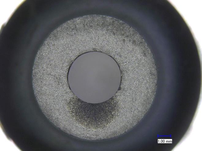
24 Low Cycle Fatigue Tests on Ni Alloys in sco2 Inconel 617 Inconel 718 Find This High corrosion resistance Coarse grain Single phase alloy Cr rich Thumbnail pattern of Natural crack initiation on sco2 side Good LCF properties Fine grain Dual phase alloy Precipitates at grain boundaries SEM of crack Initiation site facetted grain showing slip plane cracking within the grain Tested in sco Tested in Air 2 Failure initiated on the ID Failure initiated Program on Summit the OD Dislocation motion in most favorably orientated grains. -Formation of extrusion and intrusion types of defects by dislocation accumulation 24


25 Differences in Air vs sco2 Crack Initiation Mechanisms Air Air Air sco2 sco2 sco2 25
26 Low Cycle Fatigue Tests on Ni Alloys in sco2 Current Test Data Log scale* * Prior literature in air No significant LCF life debit is observed in IN718 by sco 2 at 550 o C, 0.7% max strain, 20 cpm. Little lower life observed for 0.5 % strains due to longer exposure times resulting from larger number of cycles to failure. It is expected that with longer hold-times, sco2 environment may be more aggressive resulting in lower fatigue life. 26
27 Corrosion of Ni base Super Alloys in sco2


28 Before Corrosion of Ni base Super Alloys in sco2 Find Species Diffusion using Spectroscopy After: Layered structure from sco2 corrosion Evolution of Corrosion with Time & Temperature 3 Types of sco2 Corrosion Attacks pitting Internal attack Voids Effect on Surface Properties Chemical Kinetics Model Alloys Activation energy, Ea (Joules) IN x 10 5 IN x 10 4 More details of sco2 Corrosion in: Dheeradhada V., Thatte A., EPRI International Conference on Corrosion in Power Plants, 2015
29 Models for Crack Initiation, Crack Propagation & High Energy X-Ray Tomography 29


30 Models for Crack Initiation, Crack Propagation & High Energy X-Ray Tomography Crack Initiation Model + 6 GeV Synchrotron 3D Crack Propagation Model Chemistry & Thermodynamics coupled Crack Initiation Model: Predicts Crack Evolution in 3D and # of cycles to final failure X-Ray Tomography Predicted Crack Propagation Rate 30


31 Using Bayesian Probabilistics Framework to Tie it All Together Principal Component Extraction Statistically Relevant Life Prediction Uncertainty Prediction Information on this chart is delivered with LIMITED RIGHTS in accordance with legend on the cover page. 31
32 Phase 1 ( completed) : - Performance models for DGS & HGB - Sonic Transition Models - sco2 Phase Change Models & Tests Phase 2 (completed) : - sco2 LCF and Corrosion Experiments - sco2 Chemical Kinetics & Oxidation - 3D Crack Propagation Models - High Energy X-ray Tomography. Milestones Phase 3 ( in progress): - Crack propagation tests in sco2 - Integrated Life Prediction Model - Bayesian Probabilistics Performance and Life Framework 32
33 Path to Market Mature 10 MWe sco2 turbine technology for CSP by DOE STEP Program: 50 MW Power Plant Demo 500 MW sco2 turbine ~ Other Applications : Waste Heat Recovery, Transportation 33
34 Conclusions Multi-scale coupled physics models to predict dynamic performance of HGB and DGS are developed. The models try to capture sco2 specific phenomena like sonic transitions, possibility of phase change, flow induced and rotordynamic instabilities and large perturbations in apparent heat transfer coefficients. The output of performance model is fed into 3D fracture mechanics based life prediction framework. Test campaigns to characterize corrosion of Nickel base super alloys in sco2 environment are conducted and chemical kinetics models are built. LCF behavior of Ni base super alloys in high pressure, high temperature sco2 is also being investigated using a novel experimental setup. Bayesian hybrid probabilistic models are developed to quantify uncertainty in multi-physics models and to validate models with statistical confidence. This coupled physics framework is a valuable tool to design a wide variety of sco2 turbomachines and heat exchangers, analyze their performance in supercritical and trans-critical mission cycles and predict their life for long term durability of sco2 turbomachines. 34